40
Icing Awareness for BAE Systems Regional Aircraft Operators Think Ice! REGIONAL AIRCRAFT

Icing Awareness for BAE Systems Regional Aircraft Operators
Think Ice!
REGIONAL AIRCRAFT

Welcome to this latest edition of ThinkIce! This is a revised version of the 2010issue, see preface below for more details.
It is essential for aircraft to departsnow/ice free, but an understanding of thesubsequent actions required to maintain asafe aircraft is paramount. Therefore thispublication includes articles and informationon air and ground procedures andassociated products.
Unlike the content of previous Think Iceeditions, which have been limited to iceaccretion on the outside of the airframe, thisedition introduces the issue of iceaccumulation inside fuel tanks and itspotential impact on the supply of fuel to thefeed tanks. In order to maintain a coherentmessage and because the primary aim is toindicate the most effective means for amaintenance regime to keep fuel tanks free ofwater, the complete Feed Low Level subject isconveyed in one section at the end of the‘Ground Operations’ chapter.
Other topics include advice on flying controlrestrictions and the topic of thickened de-icingfluids, pre-season de-icing, anti-icing fluidselection plus visual and tactile checking ofthe aircraft.
Our understanding of aircraft operations andthe effectiveness of associated controllingactions is enhanced by the reporting ofincidents that affect those operations.
Therefore, in order to help further ourunderstanding of icing issues, we would liketo encourage aircraft operators and anyagencies that provide supporting services toreport icing related incidents to BAE Systems.
The hazards of flight in icing conditions havelong been recognised, and various steps havebeen taken in an attempt to counter itseffects ever since our developing aeronauticalability first allowed us routinely to fly in cloud.However, despite the quantum leap instandards of understanding and technology inthe last decade or so, icing and the threat itposes, remains a major cause for concernamong aircrews.
Why should this be? Why, after over a centuryof heavier than air powered flight, should westill perceive icing as posing at least as big ahazard as it has ever been? Have we madeno real progress in countering its effects? Orhave we, manufacturer, operator and regulator,perhaps forgotten some of the basics?
Totally effective anti-icing systems are, andwill remain for the foreseeable future,impossible to achieve within the bounds ofeconomic reality. But surely we have madeprogress towards lessening the dangers?Well, yes, but perhaps not to the extent ofadvances seen in other fields of modernaviation development. The sophistication of modern systems tendsto obscure, but not alter, the fact that it is stillmore or less the same wings, tails and control
surfaces flying through the same moistureladen atmosphere that keeps us aloft and inbusiness. The same restrictions, limitationsand traps for the unwary therefore still largelyexist.
One twist is in the leading edge profiles ofmodern aerofoil sections. Even modernturboprop aircraft fly considerably faster thantheir piston engined predecessors thankspartially to improved wing aerodynamics. Theproblem is that the resulting reduced leadingedge radii are better ice collectors than theplumper profiles of the older designs, and thehigher speeds allow better droplet penetrationof leading edge pressure waves.
It may also be that the particular issues facingregional aviation recently have played a part.De-regulation leading to more directcompetition; code sharing creating stiffenedschedule obligations; advances in technologydiluting traditional airmanship skills; muchimproved cockpit facilities encouragingpenetration into worse weather conditions.Perhaps these factors and more have servedto distract us from the eternal truths of thecauses and effects of icing.
The following pages therefore offer anopportunity to regain that focus, to refresh ourmemories of what the problem is all aboutand to revisit basic air and groundprocedures.
Think Ice!
Preface to Think Ice! 2014
BAE Systems Regional Aircraft has reviewed the use of the word ‘severe’ as used in ourManuals in reference to icing. Whilst the majority of the information printed in previouseditions of Think Ice remains topical and current, the opportunity has been taken torevise and update the booklet. We have also taken the opportunity to include SupercoldLarge Drops and introduce the new regulatory icing appendices.
It is important to understsand that the intent of this booklet is to supplement theinformation in the AFM, FCOM, MOM, CM and AMM and not to supersede it. If there isany conflict in information then the official publication must be taken to be correct.

UNDERSTANDING ICING
Definition of Icing Conditions 2
The Icing Atmosphere 2
Aircraft Ice Accretion 4
Aerodynamic Degradation due to Ice Accretion 5
Icing Certification 9
AIRCRAFT ICE PROTECTION SYSTEMS
Systems Description 12
Wing and Tail De-icing Systems 13
Anti-icing Systems 13
GROUND OPERATIONS
Facts 14
De-icing and Anti-icing Fluids 14
De-icing Procedures 16
Anti-icing Procedures 18
General Precautions 19
Runway De-icers 21
Final Check Before Dispatch 21
Maintenance Recommendations 22
ContentsFLIGHT OPERATIONS
Taxying 24
Pre Take-off Inspection 24
Take-off 26
Good Operating Practices In-flight 26
Icing Intensity Criteria 27
Approach and Landing 27
After Shutdown 27
APPENDICES
Appendix I: Jets 28
Appendix II: Turboprops 32

Understanding Icing
The Icing Atmosphere
1. Cloud Forms
In-flight icing results from water dropletsremaining in a liquid state even attemperatures considerably below 0 deg. C,called supercooled droplets. In discussingaircraft icing, cloud types are placed into twogeneral classifications: stratiform (layer typeclouds) and cumuliform (clouds with verticaldevelopment). Fog differs from cloud only inthat the cloud base is at ground level.
2 Think Ice!
The Aircraft Flight Manuals (AFMs) include adefinition of icing conditions for both groundand in-flight operations. These are based onthe Total Air Temperature (TAT) or Outside AirTemperature (OAT) along with the prevailingatmospheric and ground conditions.
The AFM definition of icing conditions vary forthe different BAE Systems regional aircrafttypes and according to specific AirworthinessAuthority requirements.
Whether ice accretion will actually occur ornot depends upon many factors and thereforeflight crews must be vigilant at all times, bothon the ground and in the air.
In flight, airframe ice accretion will normallybe limited to forward facing surfaces, mostsignificantly the leading edges of the aerofoilsurfaces. The ice accretion can have a largevariety of shapes and textures ranging fromclear, thin ice (which can be difficult todetect) to coarse rime and glaze ice formswith single or double horns. The effects ofsuch accretions on the operation of theaircraft are assessed during the certificationprocess.
Definition of Icing Conditions
n Stratiform
Icing in stratiform cloud occurs normally inthe middle to lower level clouds below20,000 ft. Stratiform clouds tend to be quitestable and create extensive horizontalcoverage at different levels. Flight in icingconditions can be of long duration and formsthe criteria most often used for the design ofde-icing protection systems for wings,empennage and propellers. Icing intensitygenerally ranges from light to moderate, withmaximum values occurring at upper levelswithin these clouds.
n Cumuliform
Cumuliform clouds, of which cumulonimbus(thunderstorm cloud) is the most hazardous,are important to the icing environmentbecause of their rapid development and largeliquid water content (LWC). They cover lessarea horizontally than stratiform clouds andicing intensities can vary from light (in smallcumulus) to moderate or severe. Consequentlythey form the criteria often used for the designof anti-ice protection systems such as engineintakes, pitot static systems, heated leadingedges and control surface horns.

Think Ice! 3
2. Atmospheric Conditions
In addition to supercooled droplets, otheratmospheric conditions can individually or incombination produce ice accretions.
n Ice crystal clouds
These are very cold clouds, where moisturehas frozen to the solid or crystal state. Thisincludes snow, sleet, hail, graupel (pellets ofsoft ice) and ice crystals.
n Mixed conditions
Many icing encounters consist of ice crystalsand/or snow in combination with supercooleddroplets. These can be critical as the mixtureof ice crystals and water droplets can adhererapidly and roughly to the airframe, oraccumulate in an engine.
n Freezing drizzle and rain
Freezing drizzle and rain are large,precipitating supercooled water dropletswhich, on impact with aircraft surfaces,may result in ice accretion which isbeyond the capability of the ice protectionsystems. These conditions normally occurat lower altitudes and are associated witha melting layer or temperature inversion,where rain falls through a sub zerotemperature layer. These are extremelyhazardous conditions.
n On ground
Aircraft on the ground are susceptible toadditional icing conditions. They includefreezing fog, frost and falling or blown snow.Frost accumulations can occur overnight andwhere aircraft surface temperatures remaincold following descent from high altitudes.
Frost can also form on windscreens and fueltanks when descending a cold airframe intowarm moist air.
“Frost can also form on windscreens and fuel tanks when descending a cold airframe into warm moist air”

4 Think Ice!
Understanding Icing
Aircraft Ice Accretion
Ice forms in-flight on leading edges and frontal areas of the airframe, engine intakes andspinners/propellers by a complex process involving both meteorological and aerodynamicfactors. Meteorological factors include the liquid water and ice crystal content of the clouds,outside air temperature, droplet and crystal size and distributions. Aerodynamic factors includeaircraft speed, configuration, surface geometry and temperature, and surface adherence ofdroplets and crystals.
Rime ice accretion on a Jetstream 31.
Glaze ice accretion on a Jetstream 31.
1. Ice forms
Three basic ice forms exist: Rime, Glaze(Clear) and Frost, although mixtures of Rimeand Glaze ice are not unusual.
Rime ice is the most common form. Itsrough, opaque appearance results from smallsupercooled droplets trapping air as theyfreeze on impact with the aircraft surface. Itoften has a spearhead or streamlined shapeconforming to the shape of the surface oraerofoil and is generally encountered instratiform clouds.
Glaze ice generally forms in cumuliformclouds when temperatures are close tofreezing. Accretion is transparent and oftenproduces a flat or concave ice shape withsingle or double ‘horns’. At the airflowstagnation point on the leading edge, freezingis delayed due to both friction and the heatreleased as the water begins freezing. Thisleads to runback ice, which initially creates athin rough layer of ice either side of thestagnation line from which the flat frontedblunt shapes develop. Within the icingatmosphere, conditions vary continuously andoften suddenly, allowing both rime and glazeice to form on the same surface.
Frost is a thin layer of crystalline ice that canform on all exposed areas of the aircraft. It isgenerally associated with ground operations.(see page 14)
2. Accretion efficiency
Severe continuous icing conditions can befound near the freezing level in heavystratified clouds, or in rain. Icing is rare athigher altitudes as the droplets in the cloudsare already frozen. However, in cumuliformclouds with strong updrafts, large waterdroplets may be carried to high altitudes andstructural icing is possible up to very highaltitudes.
Indicated airspeed also influences the rate ofice accretion, the higher the speed (belowabout 250 knots IAS) the faster iceaccumulates. Kinetic heating due to skinfriction at speeds above 250 knots reducesrisks of icing. In addition the angle of attackrelative to the position of the sun also has aneffect on ice accretion.
In general, ice adheres to all forward facingsurfaces of the airframe. The accretion rate orcatch efficiency is primarily dependent on thelocation and geometry. A relatively largeradius aerofoil at moderate or low airspeedcreates a larger pressure wave ahead of theleading edge, which forces the air around it,carrying most of the moisture with it. Onlydroplets sufficiently heavy to overcome thisflow will impact on the leading edge. Thus, alarge chord aerofoil with a blunt leading edgehas low ice accretion efficiency. Conversely, anarrow radius leading edge generates asmaller pressure wave and so the accretionrate is greater. The tailplane has in general asharper leading edge section and shorterchord than the wings and consequently canaccrete ice before it is visible on the wing andat a greater rate.
3. Freezing drizzle and rain
Freezing drizzle and rain are relatively rarephenomena. However, such conditions mustbe treated with extreme caution as they canresult in severe icing. The water droplets canbe 1,000 times larger than the moisturedroplets in clouds, and ice can accreterapidly on the airframe and extend aft of thenormal accretion areas around airflowstagnation points.

Think Ice! 5
Aerodynamic Degradation due to Ice Accretion
Typical effect of ice accretion on aerofoil drag polar.
1. Drag increases, Lift decreases
The effect of ice on aircraft performance andflight characteristics depends largely on theaircraft design but also on the shape,roughness and depth of the ice. It generallyresults in decreased lift, increased drag,increased stall speeds, trim changes andaltered stall characteristics. In somecircumstances there can be a change in controlfeel and response. The available thrust fromengines can also be significantly decreased.Weight increase due to in-flight ice accretionusually has minimal effect relative to theaerodynamic degradation.
The aerodynamic penalties can be significant,not only for unprotected surfaces but also forthose protected by leading edge boot de-icingsystems, since they need to allow some icebuild-up between shedding cycles.
Wind tunnel and flight testing conducted underresearch, development and certificationprogrammes, as well as operational experiencehave all demonstrated the significant effect ofice on aircraft performance, flightcharacteristics and equipment operation. Theareas normally affected include: wings,horizontal and vertical stabilisers, engine inletsand nacelles, propellers, windshields, radome,antennae, pitot static system and cooling airintakes. The degradation of aircraft performanceand flight characteristics due to ice accretionon such areas is well understood.
The figure below shows the typical effect of iceaccretion on the airflow and lift of
unprotected aerofoils. The result is a reductionof lift at a given Angle of Attack (AOA) and asubstantial degradation in maximum lift andmaximum AOA. As illustrated, the degradationis generally more pronounced with glaze iceshapes.
Large amounts of ice build-up on anunprotected aerofoil may reduce the maximumlift by 30 to 40%, increasing the stall speed by20 kts or more (for a clean aerofoil stall speedof 100 kts).
The aircraft drag polar can be significantlyaffected, particularly on smaller aircraft, asshown in the figure on the right. Ice willincrease the drag for a given lift as well as theoptimum lift-to-drag ratio occurring at a lowerlift coefficient.
Even slight surface roughness, often referred toas 'sandpaper' ice, can result in large lift anddrag penalties. The majority of maximum liftdegradation often occurs with the first 1/4 to1/2 inch of ice accretion (6 to 13 mm).
Further increase in ice depth and surfaceroughness has a less dramatic degradation oflift but will produce additional drag. Liftdegradation is associated with an increase install speed and decrease in stall AOA. Withsignificant ice accretion, the stall speed isincreased substantially and pre-stall buffet mayprecede the activation of the stall warningsystem, particularly on aircraft with an airframeleading edge boot de-icing system.
Control and trim effectiveness may be reduced.Aileron, rudder and elevator control systemscan be prone to freeze if water deposits, snowor ice are not properly drained from criticalareas. Control surfaces may freeze or jam withexternal ice accumulation.
The power required to achieve or sustain aflight path can be increased significantly due toice formation on the unprotected surfacesincluding areas of the airframe not visible fromthe cockpit. For turboprops, ice accretion onthe propellers can significantly decrease theavailable thrust. Asymmetric ice shedding frompropellers or jet engine fans can also give riseto vibration.

6 Think Ice!
Understanding Icing
2. Wing stall
The stalling of a regional transport aircraftwing normally results from flow separationfrom the top surface. On the BAE Systemsregional aircraft types this usually starts at theinboard wing trailing edge or at the wing-to-fuselage and wing-to-nacelle junctions. TheBAe 146 and Avro RJ aircraft are all fittedwith stall triggers (toblerones) on the inboardwing leading edges. These simple devicesensure that the airflow separation initiates onthe inboard wing. As AOA is increased, theseparated flow spreads forward and outward,preventing any pitch up at the stall. Vortexgenerators on the wing top surface arecommonly used to harness local airflow energyto delay separation at the trailing edge.
All of the BAE Systems regional aircraft typeshave a stick shaker installed to provide a clearindication to the pilot that the aircraft isapproaching the onset of a stall. The marginabove the stall at which the stick shakeoperates exceeds the minimum airworthinessrequirements, but will vary with flapconfiguration, power and rate of approach tothe stall.
Stall identification is defined either throughthe inherent aerodynamic characteristics ofthe aircraft (HS748 and ATP), or by a stickpusher device, incorporated in the elevatorcontrol circuit, that induces an abrupt nosedown pitch change (J31/32, J41, BAe 146and Avro RJ).
The J31/32, HS748, and ATP aircraft utiliselift transducers, located on the leading edgeof each wing, to sense the airflow patternover the wing and provide the signal for the stick shaker and, where fitted, stick pusher.
On the J41 and BAe 146/Avro RJ the signalsfor stick shake and stick push are provided byheated angle of attack vanes mounted oneach side of the forward fuselage.
With the aircraft clear of ice, the stick shakerprovides a clearly distinguishable warning ofapproach to the stall. Where the stallidentification is provided by the naturalaerodynamic characteristics, acceptableindications include a nose down pitch, heavybuffeting and aircraft rolling motion. Naturalstalling on aircraft with a stick pusher systeminstalled should not usually be experienced bypilots.
With ice accretion on the wing leading edges,the mechanism of stall development remainsthe same but starts at a lower AOA andtherefore higher speed. In addition the airflowdoes not have the same level of energyaround vortex generators (if fitted) for them todelay progression of the stalled area aseffectively as on a clean wing.
The overall effect of ice accretion on thestalling characteristics is also dependent onthe type of airframe ice protection systeminstalled. In general, the effect of iceaccretion on aircraft with leading edge bootde-icing systems installed is more adversedue to the ice accretion required prior tooperation of the system and inter-cycle icebuild-up.
Where airframe anti-icing systems are installedas on the BAe 146 and Avro RJ, the protectedareas of the airframe will in general be clearof ice and so the effect of ice on stallingcharacteristics can be less pronounced.
However, with some of the more adverse iceshapes the stall warning may be preceded byairframe buffet and the stick pusher (whenfitted) may be preceded by some lateralinstability, wing rock, pitch nodding or ‘g’breaks. This is more probable on the aircrafttypes with wing mounted lift transducers, dueto ice accretion around the protected area ofthe vanes. With ice accreted on the leadingedges, high rates of descent can develop athigh flap angles. It does not require anexcessive level of ice accretion to generatethese wing stalling characteristics, accretionsof just 12.7 mm (1/2 in) can be sufficient.The Jetstream 41 stall warning andidentification system was modified so that thestick shaker and stick pusher operate at alower AOA in icing conditions. The ‘Ice Mode'system is armed by the pilot's selection ofengine anti-icing and ensures that the stallwarning and identification system operatescorrectly when the aircraft has accreted ice onthe leading edges. The relevant speeds areincreased with the ‘Ice Mode’ armed.
On the BAe 146 and Avro RJ the stall warningand identification system has beendemonstrated to operate correctly at thenormal AOA settings, with the airframe iceprotection operating normally. As a resultthere is no adjustment required for flights inlight or moderate icing conditions.
Recovery from a stall, with or without iceaccretion on the airframe, is achieved byreducing the pitch attitude, allowing the speedto rise and the AOA to reduce after thenatural stall or operation of the stick pusher,whilst applying power.

3. Tailplane stall
The phenomenon of tailplane stall is ofconsiderable interest, particularly within theregional aircraft industry. It is one that hasaffected aircraft throughout the history offlight, including modern turboprop and jetaircraft. In order to increase the generalawareness and understanding of itsmechanism, an explanation of the causes isgiven below.
A tailplane stalls when the maximum angle ofattack for the tailplane, either positive ornegative, is exceeded. The followingdiscussion addresses the more commonnegative tailplane stall and is concentrated onaircraft with un-powered mechanical elevatorcontrols and airframe de-icing systems.
Normally, the tailplane creates a force (lift) inthe downward direction to balance wing andfuselage pitching moments. Under normalconditions, without ice accreted, aerodynamicpressures above and below the elevators areroughly equal and thus create no significantcontrol surface hinge moment (see illustrationbelow).
With ice accreted on the tailplane, flowseparation may develop on the lower surface,which will limit the maximum amount ofdownward lift the tailplane can generate andcause the tail to stall at a lower AOA.
The development of flow separation will alsoresult in an adverse change in the relativepressure distribution over the upper and lowersurfaces. Since the forces about the elevatorhinge and the resultant stick forces sensed by the pilot are balanced by aerodynamic andmechanical system forces, any change to theairflow can affect the stick forces.
Tailplane stall may therefore be sensed by thepilot as a control anomaly (e.g. sticklightening), pitch instability or nose down trimchange. For un-powered mechanical elevatorcontrols, the magnitude and direction of stickforce anomalies will depend upon the size andconfiguration of the elevator control systemand the difference in pressure between theupper and lower surfaces.
In the worst case, the elevator would beforced to the nose down stop if unrestrained,and the aircraft would respond accordinglyby pitching nose down, often rapidly. Thiswould be in addition to the aircraft’s naturalnose down pitching tendency as the tailplaneloses downward lift effectiveness, and couldrequire an extremely high pull force on thecontrol column to recover.
Think Ice! 7

4. Flap extension
Extending the flaps increases the airflowdownwash angle from the wing and thetailplane negative AOA (see figure opposite).For a given flap setting, the AOA on thetailplane becomes more negative withincreasing speed because of the reduced AOAof the wing (more nose down, more tail up).Therefore, at higher flap angles and airspeedsthe wing stall margin is increased, but thetailplane stall margin is further reduced.
The occurrence of stall on any aerofoilcontaminated by ice almost always occurs ata lower angle of attack than a clean aerofoil,hence any ice accretion reduces the tailplanestall margin further. It is worth emphasisingthat ice can form on the tailplane at a greaterrate than the wing, primarily due to itsrelative small size and smaller leading edgeradius. This can lead to a significant buildup of ice which is not evident fromobservation of ice accretion on other areasof the airframe.
In general, the most adverse combination offactors for tailplane stall is ice accretion ofcritical shape, roughness and location,maximum flap extension, forward centre ofgravity, high power and nose down elevatorcontrol inputs (which result in a tailplanecamber adverse to the airflow). On the BAESystems Regional Aircraft turboprop types,higher airspeeds close to the maximum flapextension speed are also adverse, althoughflight testing of the HS748 demonstrated thatspeeds close to the normal landing speedscan also be critical.
However, it should be understood thattailplane stall factors can be complex,and consequently symptoms for crewrecognition and appropriate recoveryactions are specific to the aircraft typeand configuration. This is addressedfurther in Appendix II: Turboprops.
8 Think Ice!
Understanding Icing
Effect of flap angle on tailplane angle of attack.
Icing Certification
To be approved for flight into known orforecast icing conditions, an aircraft must beequipped with ice protection systems, whichare designed to provide protection for therange of conditions likely to be encountered inservice. The BAE Systems Regional Aircraftrange of aircraft has been certificated forflight in icing conditions in accordance with avariety of certification bases. Suchcertifications do not, however, allowunrestricted flight with ice on the aircraft.They also assume that flight crews follow alldrills and procedures and exercise appropriateairmanship. This section provides details ofthe current Federal Aviation Authority (FAA),European Aviation Safety Agency (EASA) andJoint Airworthiness Authority (JAA) certificationrequirements for flight in icing conditions.
1. Certification requirements
The applicable icing environment within whichthe aircraft must be able to operate safely forFAA and EASA certification is defined byFAR/CS/JAR-25 Appendix C. Design criteriaare described in terms of cloud LWC, medianvolume droplet diameter, ambienttemperature, cloud type and horizontal extent.The cloud types are stratiform for maximumcontinuous intensity of icing conditions andcumuliform for intermittent maximumintensity. Small aircraft certificated under FARPart 23 rules (such as J31/32) must meetthe same icing design criteria as Part 25 largetransport category aircraft.
2. Operational regulations
The operating rules and aircraft ice protectionsystems required for flight into known orforecast icing conditions, including groundoperations, are enforced by the FAA in Parts91, 121 and 135 of the regulations. Forcommercial aircraft operating under Europeanregulations the applicable requirements aregiven in EU-OPS 1.
Detailed guidance material for groundoperations is provided by airworthinessauthorities, including FAA Advisory CircularAC20-117. In all cases the emphasis is on a‘clean aircraft’ policy for take-off and this hasalways been observed for the BAE Systemsrange of regional aircraft.
3. Compliance demonstration
In order to demonstrate compliance with thecertification regulations, extensive analysisand testing are required for the ice protectionsystems and the aircraft handling andperformance characteristics.
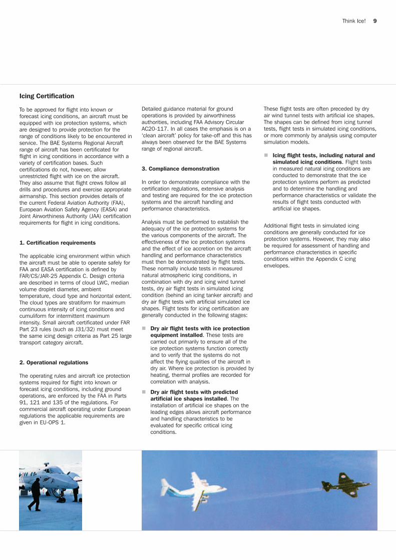
Analysis must be performed to establish theadequacy of the ice protection systems forthe various components of the aircraft. Theeffectiveness of the ice protection systemsand the effect of ice accretion on the aircrafthandling and performance characteristicsmust then be demonstrated by flight tests.These normally include tests in measurednatural atmospheric icing conditions, incombination with dry and icing wind tunneltests, dry air flight tests in simulated icingcondition (behind an icing tanker aircraft) anddry air flight tests with artificial simulated iceshapes. Flight tests for icing certification aregenerally conducted in the following stages:
n Dry air flight tests with ice protection equipment installed. These tests are carried out primarily to ensure all of the ice protection systems function correctly and to verify that the systems do not affect the flying qualities of the aircraft in dry air. Where ice protection is provided byheating, thermal profiles are recorded for correlation with analysis.
n Dry air flight tests with predicted artificial ice shapes installed. The installation of artificial ice shapes on the leading edges allows aircraft performance and handling characteristics to be evaluated for specific critical icing conditions.
These flight tests are often preceded by dryair wind tunnel tests with artificial ice shapes.The shapes can be defined from icing tunneltests, flight tests in simulated icing conditions,or more commonly by analysis using computersimulation models.
n Icing flight tests, including natural andsimulated icing conditions. Flight tests in measured natural icing conditions are conducted to demonstrate that the ice protection systems perform as predicted and to determine the handling and performance characteristics or validate theresults of flight tests conducted with artificial ice shapes.
Additional flight tests in simulated icingconditions are generally conducted for iceprotection systems. However, they may alsobe required for assessment of handling andperformance characteristics in specificconditions within the Appendix C icingenvelopes.
Think Ice! 9

4. Ice accretion
During certification flight testing forassessment of the handling and performancecharacteristics for an aircraft with airframe de-icing systems, ice accretion on both theunprotected and protected leading edgesmust be considered. The ice accretionrequirements for protected areas must beconsistent with the procedures for operatingthe protection system, and should include theice accumulation required prior to systemactivation and accretion during the rest periodof a de-icing cycle. In addition, failure of theairframe ice protection must also be assessedand failures which require the aircraft to leaveicing conditions established.
5. Handling
Detailed advisory material for thedemonstration of handling and performancecharacteristics in icing conditions is providedby the FAA, JAA and EASA. Satisfactorystability and control must be demonstratedwith the most critical ice accretion pertinentto each flight phase and related configurations(including take-off, climb, cruise, descent,holding, approach and landing). In particular,extensive flight testing is required to examinestall warning and stall characteristics,longitudinal controllability (including pushoversto zero ‘g’ for assessment of tailplane stallmargin), flaps configuration changes andlongitudinal, lateral and directional stabilityand trimmability.
6. Performance
Assessment of aircraft performance for flightin icing conditions must not only account foraccumulated ice on unprotected surfaces andany residual ice on protected surfaces, butalso the effects of the ice protection systemson engine power.
To ensure safe flight in icing conditions, theeffect on performance must be established.Comparison of climb rates and cruise speedsof the clean aircraft and the aircraft with iceaccreted should be used to determine theperformance degradation. Stall speeds withice accreted are used to establish safe flightspeeds, from which scheduled performancecan be derived.
The level of scheduled performance dataprovided in the Aircraft Flight Manual andOperating Manuals depends on aircraft typeand the requirements of specific AirworthinessAuthorities. It is worth noting that aircraftperformance can be significantly degradeddue to ice accretion on unprotected areas ofthe airframe not visible from the flight deck.
7. Take-off
Aircraft which are certificated for flight in icingconditions are not certificated for take-off withice formations or any other surfacecontaminant. Such ice formations orcontamination must be cleared from theairframe and the aircraft sustained in a cleancondition prior to take-off.
Although not specifically required byAirworthiness Authorities, flight testing hasbeen carried out to investigate the effects onperformance and handling by the applicationof Type II and IV anti-icing fluids on the BAESystems regional aircraft types. Theirpresence on wing and tailplane surfaces wasdemonstrated not to affect the aircraft stallcharacteristics, climb performance or cause anoticeable loss of lift during take-off. However,in some cases an increase in stick force wasrecorded during take-off rotation, but theaircraft remained fully responsive to controlinputs. In general, the rotation speeds of theBAe 146/Avro RJ are sufficiently high that themajority of the fluid will be sheared off thewing and tail and stick forces remain normal.
10 Think Ice!
Understanding Icing
Ice accretion on landing gear.
Ice accretion on the Jetstream 41 wing during normaloperation of the airframe de-icing boots.
Ice accretion on the Jetstream 41 wing following asimulated failure of the airframe de-icing boots.

8. Landing
Assessment of the aircraft handlingcharacteristics during approach and landingcan be conducted with either artificial iceshapes or, on an opportunity basis, during thenatural icing trials if substantial ice accretionsremain on the airframe. In these circumstancesincreased landing speed is required.
9. Freezing drizzle and rain
A Turboprop accident in 1994 drew attentionto freezing drizzle and atmospheric icingconditions that were outside the existingFAR/CS/JAR Appendix C icing envelope whichhad been used for certification of largeaircraft. Another atmospheric icing condition,also outside the Appendix C icing envelope isfreezing rain. These icing conditions constitutean icing environment known as SupercooledLarge Drops (SLD). Flight through such icingconditions may cause airframe ice accretionthat exceeds the capabilities of the aircraft’sice protection systems, and may seriouslydegrade performance and control.
BAE Systems recommend that suchconditions should be avoided or leftimmediately.
For certification tests on new aircraft allNational Aviation Authorities are introducingregulations to improve the level of safety whenoperating in icing conditions. In order toachieve this Appendix O is being issued to CSand FAR, and this Appendix will also addressengines and pitot tubes.
10. Systems
Extensive flight testing in a broad range ofnatural icing conditions is required to assessthe performance of all de-icing and anti-icingsystems and to establish procedures for theiroperation. Ice protection system performanceand effectiveness must be evaluated both fornormal operation and following delayedactivation or simulated failure of the system.
Icing wind tunnels have also been usedextensively for the regional aircraft types of BAESystems for assessment of the ice protectionsystems, in particular leading edge de-icingboots and electrically heated systems such as pitot probes and stall vanes. Engine ice protection systems, de-icing and anti-icing,are generally developed through many hours of ground testing in icing test cells prior to flighttesting in natural icing conditions or insimulated icing conditions using a tanker sprayaircraft. The icing plume created by tankeraircraft can lead to ice accretions well beyondthat generally encountered in natural icingconditions. However, if the conditions are withinthe design icing envelopes then the protectedarea should remain essentially clear of ice.
11. Summary
All regional aircraft types of BAE Systems arecertified for flight into known and forecasticing conditions, and are designed to meet,and usually to exceed, the criteria demandedby the Airworthiness Authorities.
However, it should be remembered that theaircraft are only certificated and approved forflight in supercooled water droplet conditions,as defined in FAR/CS/JAR-25 Appendix C.
It is important that flight crews are consciousthat every atmospheric icing encounter isdifferent and that hazardous conditions canoccasionally be met which may be beyond thecapabilities of the aircraft's protectionsystems.
Think Ice! 11
Post flight ice accretion on the outboard wing of aJetstream 41.
Jetstream 31 engine intake and propeller icingdeliberately accreted during tanker trials.

Aircraft Ice Protection Systems
1. Concept of de-icing and anti-icing
It is useful to clarify what is meant by theterms ‘Anti-icing’ and ‘De-icing’, since theirsometimes random use when applied toaircraft systems suggests that some confusionmay exist. In strict terms, the followingdefinitions could be said to apply:
n Anti-icing is the prevention of ice formation, generally by means of heating (electrical, ducted engine bleed air, engineoil etc.).
n De-icing is the removal of ice that has accreted, normally by means of cyclic heating or the application of a physical impulse (commonly achieved on leading edges by pneumatic boot inflation).
ns
12 Think Ice!
In order to maintain the safety levels andperformance of the aircraft in icing conditions,all BAE Systems regional aircraft types arefitted with comprehensive ice protectionsystems. Whilst installations andspecifications vary between the differentaircraft types, the principles remain the same.
Systems Description
However, where de-icing is provided by cyclicheating due to a restriction on the poweravailable, and not from a requirement toallow deliberate ice accretion for the systemto function effectively (as with inflatableboots), it may be argued that it is in reality ananti-icing operation. Consequently,descriptions of ice protection systems such aselectrically protected propellers and engineintakes can appear in manufacturers’manuals for example as either:
De-icing - Wing and tail leading edges- Propeller leading edges- Engine intakes
Anti-icing - Windshields- Engine intakes- Pitot heads and static plates- Temperature probes- Angle of attack (stall) vanes- Control surface balance horns
2. Ice detection methods
The certificated primary means of icedetection on all the BAE Systems regionalaircraft types is by visual inspection of theairframe by the flight crew. This shouldinclude observation of the following areas:
n Windshield.
n Windshield pillars.
n Windshield wiper bosses.
n Wing leading edges (these can be illuminated at night).
n Propeller or engine fan spinners.
Ice detection systems, which provide asecondary (advisory) means of detection, arefitted to some types. These provide the flightcrew with a cockpit indication when ice isaccreted on the detection device.
Ice accretion on windshield - hazardous icing conditions.
Vertical Stabilizer De-icing Boot
Elevator Horn Heating Mat
PropellerHeating Mat
Heating AOAVanes
WindscreenHeatingElements
Windshield Wipersand Washers
Heated StaticPlates
Ice Detector TAT ProbeHeated Pitot
Head
Inboard WingDe-icing Boot
Engine IntakeHot Air Anti-icing
Ice ObservationLight
Inboard HorizontalStabilizer De-icing
Boot
Outboard Wing De-icing Boot
Mid Wing De-icing Boot
System layout shown on a Jetstream 41.
Outboard Horizontal Stabilizer De-icing
Boot

Think Ice! 13
The leading edges of the wings and stabilisersare de/anti-iced by either inflatable boots orducted bleed air. Operation of hot air systemsis prohibited during take-off and landing inorder to limit the amount of bleed taken fromthe engines. Ground operation is alsoprohibited as overheating could distort theleading edges. The BAe 146/Avro RJ type hasa hot air de-icing system on the inboardsection of the wing, designed to remove iceprior to holding or landing, and a hot air anti-ice system on the outboard section of thewing and on the tail.
n Hot air versus inflatable boots
The fundamental reason why turbopropaircraft are generally fitted with pneumaticboot de-icing systems, as opposed to theanti-icing heating systems found on most jettransport aircraft, is found in the powerrequired for them to function.
Wing and empennage anti-icing systems mustnot only prevent ice forming on leading edges,they must also provide enough heat toevaporate the moisture to prevent it fromrunning back and freeze on the unprotectedsurfaces. Therefore they need very muchmore bleed air to operate than pneumatic de-icing systems do, bleed air that simply is notavailable from the turboprop engine.
Thus while the jet engine core can absorbthe loss of propulsive power incurred indriving an anti-icing system, similarextraction demands placed on the turbopropwould impose proportionally much greaterperformance penalties. These are normallyunacceptable when balanced against theperformance degradation due to airframe iceaccretion.
1. Turbo-fan engine
Engine intakes, compressor inlet ducts andfuel control sensors are all heated to preventthe formation of ice. The systems aredesigned for continual operation (somerestrictions may apply on the ground) andshould be selected ON when icing conditionsexist.
2. Turbo-propeller
Each blade is fitted with an electrically heatedrubber mat in the root area controlled by a cyclictimer. Any ice forming on the unheated portionwill shed by centrifugal force, the fuselage beingprotected by a Kevlar shield adjacent to thepropeller disc zone (except for the HS 748 type).Propeller heating systems must only be usedwhen the engine is running to preventoverheating of the propeller leading edges.
3. Windshield
All forward facing windshields and some sidescreens are electrically heated. These arecontinuously heated to provide not only iceprotection but demisting and on some typesto increase the impact strength of the screen.
4. Elevator horn
The unshielded elevator aerodynamic balancehorns on the J31/32 and J41 are anti-icedusing electrically heated mats.
5. Pitot head, static plate, TAT probe and AOA vane
To prevent ice accretion on pitot heads, staticplates, temperature probes and AOA vanes,independently switched and sourced electricalheating is provided. These systems areselected ON during the after start checks orthe pre take-off checks.
6. Continuous ignition
Although not normally associated with aircraftde-icing/anti-icing, the use of continuous andautomatic ignition systems is important toprevent the flame-out of an engine due toingestion of large amounts of precipitation orslush.
System layout shown on a BAe 146/Avro RJ.
Wing and Tail De-icing Systems
Anti-icing Systems
Wing Anti-ice
Tail Anti-ice
Heated Drain Mast
Wing Anti-iceEngine Intake Anti-ice
Ice Detector
Anti-icePitot Head
Anti-iceStatic Plates
Anti-iceAirflow Sensor Vanes
Windshield De-ice/Anti-ice
WindshieldWipersWashers
Q Pot Head
Engine Intake Anti-ice
Heated Drain Mast
Wing De-ice/Anti-ice

Ground Operations
14 Think Ice!
The basis for safe flight operations in coldweather conditions is the ‘CLEAN AIRCRAFTCONCEPT’. This involves de-icing and ifnecessary anti-icing an aircraft so that thesurfaces are clear of ice, snow, slush or frostat take-off.
This section provides information on groundoperations in cold weather conditions, andis mostly applicable to all aircraft types. Formore specific details on jet aircraft seeAppendix I, and for turboprops seeAppendix II.
n Any deposit of ice, snow or frost on the external surfaces of an aircraft may drastically affect its flying qualities because of reduced aerodynamic lift, increased drag and modified stability and control characteristics.
n Freezing deposits, including anti-icing fluidresidues, may cause moving parts such aselevators, ailerons, flap actuating mechanisms, etc. to jam and create a potentially hazardous condition.
n Engine operation may be seriously affected by the ingestion of snow, ice or de/anti-icing fluid into the engine, causingengine stall or compressor damage.
n Most cold weather operating difficulties are encountered on the ground, the most critical periods being immediately pre-flight and post-flight. Proper diligence on everyone’s part concerning ground operation is an important factor in successful cold weather operations.
n A thorough pre-flight inspection is extremely important when operating in winter conditions. At very low temperatures the urge to hurry is natural, particularly when the aircraft is outside, but unfortunately this is the time when thegreatest care is needed.
n Due to the wide climatic variations encountered during cold weather aircraft operations, individual operators should designate a cold weather operations period (e.g. from October to April in the Northern Hemisphere) for the implementation of their cold weather operating procedures tailored to their environment and experience. Early preparation for winter season operations will always prove beneficial.
n Given good maintenance practices, including frequent inspections for and cleaning of anti-icing fluid residues, and adherence to the recommendations madein the Aircraft Maintenance Manual ATA Chapter 12, cold weather operations can be confidently performed and a high level of dispatch reliability maintained.
Facts
“Taking off with frost is like walking toward the edge of a cliff blindfolded”.Kurt Blankenship, NASA research pilot.
De-icing and Anti-icing Fluids
Operators are advised that it is theirresponsibility, in accordance with operatingguidelines issued by their relevantairworthiness authority, that suitable de/anti-icing fluids are used. BAE Systems RegionalAircraft advise that fluids approved to thelatest revisions of the Society of AutomotiveEngineers (SAE) AMS 1424 and AMS 1428are suitable for use, if they are applied inaccordance with the recommended de-icingand anti-icing procedures, and an appropriateinspection and cleaning programme isadopted to minimise the build-up of residues.
There are four basic types of de-icing/anti-icing fluids, as follows:
‘Type I’ Fluids
n Type I fluids are ‘unthickened’ and have a relatively low viscosity.
n They have good de-icing properties but provide negligible protection against re-freezing.
n They are used predominantly for removing frozen deposits from aircraft surfaces, either in the first step of a two-step operation, or where precipitation has stopped.
n In undiluted form they are not to be used at ambient temperatures below -10 deg. Cdue to adverse aerodynamic effects.

Think Ice! 15
n Type I fluids are normally colourless in appearance.
‘Type II’ Fluids
n Type II fluids contain thickening agents which enable the fluid to be deposited as a film and to remain on the aircraft surfaces until the time of take-off.
n This film provides a longer holdover time especially in conditions of freezing precipitation, providing anti-icing protection against re-freezing or further accumulation in precipitation conditions.
n The holdover time can be extended by increasing the concentration of fluid in the fluid/water mix.
n The fluids are designed to flow off the wings when subjected to shear forces at take-off, causing little effect on the aircraft’s aerodynamic performance.
n Type II fluids are normally straw coloured in appearance.
‘Type III’ Fluids
n Type III fluids contain thickening agents which enable the fluid to be deposited as a film and to remain on the aircraft surfaces until the time of take-off.
n Type III fluids reduce in viscosity faster than type II and type IV fluids and thus provide anti-icing protection for a shorter period.
n The holdover time can be extended by increasing the concentration of fluid in the fluid/water mix.
n Type III fluids are normally bright yellow in appearance.
‘Type IV’ Fluids
n Type IV fluids have been developed in recent years to increase holdover times by the further addition of thickening agents.
n These fluids should only be used on BAE Systems aircraft subject to certain operating restrictions.
n Type IV fluids are normally coloured green. As with Type II, their holdover times can be extended by increasing the fluid concentration in the fluid/water mix.
All fluids must be used in accordance with themanufacturers’ recommendations. Ifimproperly used, they can cause undesirableand potentially hazardous changes in aircraftperformance, stability and control.
Fluids used during ground de/anti-icing arenot intended for, and do not provide, iceprotection during flight.
Pre-season Fluid selection
When developing their Winter Operationspolicy, in addition to the normal considerationof hold-over times and fluid concentration,operators are strongly recommended todetermine the residue forming characteristicsof the Type II, III and IV fluids that areavailable at the various stations for theiroperations.
It has been seen that fluids with higherresidue characteristics may lead to heavierand faster residue build-up, which increasesinspection and cleaning frequencies, and thepotential for a frozen control incident to occur.Information on the residue characteristics forall Type II, III and IV fluids is published by theAnti-Icing Materials International Laboratory(AMIL) on their website at:http://www.uqac.ca/amil/en/, and updatedregularly. Although these residue curves arenot named, fluid manufacturer contactinformation is provided. It is recommendedthat each relevant fluid manufacturer iscontacted to find the position of the fluidsavailable on the graph, to determine the bestfluid for use. The fluid with the lowest curveshould be chosen to minimise the build-up ofresidues.

16 Think Ice!
Ground Operations
1. Mechanical means
Soft snow and slush should be first removedusing brooms, soft hand brushes or rubberscrapers. Do not attempt to remove snow bybeating it and do not use tools to scrape orscratch compacted snow from surfaces orfrom between fixed and movable surfaces and/or components. Using de-icing fluidsinitially for complete snow removal isineffective and could result in a weak mixturere-freezing and creating an icing conditionmore difficult to remove. It is always good practice as a pre-step process to removelarge amounts of contamination prior to theapplication of de-icing or anti-icing fluids, as itreduces the quantity of glycol-based fluidneeded.
Remove snow from upper fuselage areasbefore heating the aircraft interior, as waterfrom melting snow might freeze over windowsand lower fuselage.
Make sure that wing and empennage controlsurfaces are not damaged by implementsused for snow removal, and when clearingsnow from upper fuselage, avoid damageto communications antennae.
Remove all snow accumulations on fuselagenose forward of the windscreen as snowmight blow back and stick to it, restrictingpilot’s visibility during take-off.
Remove snow from the top surface of thehorizontal stabilisers forward to the leadingedge. After being placed in the neutralposition, the elevators should be cleaned fromtheir leading edge towards their trailing edge.With the rudder in the neutral position, thevertical stabiliser and rudder should becleaned from the top, downwards.
Snow removal from the wings should start atthe root, working towards the tip and trailingedge, avoiding the control surfaces. Afterbeing placed in the neutral position, thecontrol surfaces should be cleaned from theirleading edge towards their trailing edge.
Thick accumulation of snow can be removedfrom aircraft surfaces with the use of anIngersoll-Rand type heavy-duty air compressor,with a cold blast directed from a cherry-pickertype boom at a safe distance of two to sixmetres depending on air pressure used.
Lighter snow accumulations can be removedfrom fuselage and wing upper surfaces byworking a length of cotton rope, cloth orsmall-diameter fabric fire hose back and forthover the surfaces.
If using warm air to remove snow, continueheat application until the surface is completelydry. Exercise care not to overheat structure orsystem components (see caution; in theoperating manuals). A heating sourceproviding a large volume of warm, dry air ismore effective than a small volume of hot airand can be used with less danger ofoverheating.
Hot air can also be used to further clean theengine intakes where permitted by the AMM.These areas should always be inspected, evenwhen blanks are fitted. This was oncereported on an aircraft parked outside all nightwith blanks fitted. In the morning, the crewmanaged to remove two large handfuls of iceper engine, which had formed overnight as aresult of water entering, pooling and freezing,despite the blanks having been fitted. If icehas accumulated on fan blades, hot air is theonly method to clean this deep inside theengine area.
For window areas, externally-applied heatshould be used with care since hightemperatures on cold windows will crack orcraze the transparency.
When the aircraft is clean, all openingsbetween fixed surfaces and flight controlsshould be carefully checked for the presenceof snow, slush or ice which could impair freemovement. Bottled nitrogen or a source of dryunheated air may be used to blow snow outof these areas.
De-icing Procedures
CAUTION: The instructions given in theAircraft Maintenance Manual (AMM) areoverriding, therefore only carry out theprocedures permitted in that manual.
De-icing is the procedure by which snow, ice,frost, and/or slush are removed from allsurfaces, openings and hinge points of anaircraft to provide clean surfaces.
De-icing gives very limited to NO protectionagainst further accumulations of ice or snow.De-icing measures can be accomplished byseveral means, such as:
n Mechanical means (broom, warm air)n Heated hangarn De-icing fluids
Mechanical means or a heated hangar shouldbe used to de-ice the aircraft’s ‘no spray’zones (Refer to AMM chapter 12).
Large deposits of snow and slush must firstbe removed by mechanical means.

Think Ice! 17
2. De-icing fluids
The de-icing fluids are:
n Heated water (recommended).
n Type I fluid.
n Heated concentrates or mixtures of water and Type I fluid (recommended).
n Heated concentrates or mixtures of water and Type II fluid.
n Heated concentrates or mixtures of water and Type III fluid.
n Heated concentrates or mixtures of water and Type IV fluid.
The use of Type II, III or IV fluids for de-icingis not recommended as it increases the build-up of residues.
For maximum efficiency, all of the above de-icing fluids should be heated (60 to 90 deg. Cat the nozzle exit) and applied close to thesurface of the skin to minimise heat loss. Aminimum distance of 2.5 yards (2.3 metres)must be maintained though to preventdamage to the skin). The heat in the fluideffectively melts any frost, as well as lightdeposits of snow, slush and ice and breaksthe bond between frozen deposits and theaircraft structure. The hydraulic force of thefluid spray is then used to flush off theresidue.
The fluids must be used in conjunctionwith the manufacturer’s instructions andapproved holdover guidelines.
3. De-icing fluid application
BAE Systems recommend the followingmethods to de-ice the aircraft:
n Hot type I: apply heated SAE Type I de-icing fluid (diluted in accordance with manufacturer's instructions).
n Hot water: apply at a temperature of 60 to 90 deg. C at the nozzle exit. This methodis only permitted with OAT > -3 deg. C
The landing gears and wheel wells should becleared of snow and slush, preferably using abrush.
Check that drain holes are open and flowfreely.
If snow, slush or ice is suspected in seals orcontrol surfaces, a detailed check isadvisable. The aircraft should not be clearedfor flight until the seals, gaps and all controlcomponents are completely clear and dry.
After completing snow and slush removal, afunctional check of each flight control systemshould be performed.
For window areas, externally-applied heatshould be used with care since hightemperatures on cold windows will crack orcraze the transparency.
and in conjunction with a two-step de- andanti-icing procedure (Refer to Anti-icing Procedures chapter).
Removal of snow: a nozzle setting sufficientto flush off deposits should be used. For heavydeposits of wet snow a high fluid flow will berequired, whereas with light deposits of dry orwet snow, similar procedures as for frostremoval may be employed.
With a heavy accumulation of snow, alwaysconsider removing the worst of the snowmanually before attempting a normal de-icingprocedure.
Removal of frost and light ice: a nozzlesetting giving a solid cone (fan) spray shouldbe used. This ensures the largest dropletpattern available, thus retaining the maximumheat in the fluid.
Removal of ice and frozen snow: heatedfluid should be used to break the bondbetween ice deposits and the aircraft skin.Making use of the high thermal conductivity ofthe metal skin, the adhesion of a large area offrozen snow or glazed ice can be broken bydirecting a jet of hot fluid at close range ontoa number of spots.

18 Think Ice!
Ground Operations
Anti-icing Procedures
Anti-icing is a procedure which providesprotection against the formation of frost or iceand accumulation of snow or slush on cleansurfaces of the aircraft for a limited period oftime (the holdover time).
1. Holdover time
This is the ESTIMATED time for which an anti-icing fluid will prevent the formation of frost orice and the accumulation of snow on theprotected surfaces of an aircraft.
Holdover times for specific approved fluidsshould be obtained from current tablespublished by the FAA (Federal AviationAdministration), TC (Transport Canada) or theAEA (Association of European Airlines) or thespecific fluid manufacturer.
A range of holdover times is often quoted; thelower value is the estimated time formoderate precipitation rates and the uppervalue is the estimated time for lightprecipitation rates.
Heavy precipitation rates, high moisturecontents, high wind velocity or jet blasts mayreduce holdover time below the lowest timestated in the range. Holdover time may alsobe reduced when the aircraft skin temperatureis lower than the OAT. Therefore indicatedtimes should be used only in conjunction witha pre-take-off check.
The holdover time depends on the fluidtype, weather conditions and ambienttemperature. After determining theholdover time applicable, the crew shouldensure that it will not be exceeded due toanticipated taxy and holding times prior totake-off.
2. Anti-icing fluids
Anti-icing fluids must always be applied on aclean surface. When applicable, always carryout a complete de-icing of the aircraft beforestarting the anti-icing procedure.
The anti-icing fluids are:
n Heated Type I fluid.
n Heated mixtures of water and Type I fluid.
n Concentrates or mixtures of water and Type II fluid.
n Concentrates or mixtures of water and Type III fluid.
n Concentrates or mixtures of water and Type IV fluid.
The following surfaces should be protected:
n Wing upper surfaces, leading edges and ailerons.
n Horizontal stabiliser upper surfaces, including leading edges and elevator uppersurfaces.
n Vertical stabiliser and rudder.
n Fuselage upper surfaces depending upon the amount and type of precipitation.
n Flaps should normally be retracted whilst the aircraft is on the ground so that they are protected from any ice formation.
Areas de-iced or anti-iced first will generallyfreeze first. Therefore areas which are visiblefrom the cockpit should be anti-iced first sothat during the pre-take off check the crewwill have the assurance that other areas ofthe aircraft are clean.
CAUTION: Anti-icing fluid may not flow evenlyover wing leading edges, horizontal andvertical stabilisers. These surfaces should bechecked to ensure that they are properlycoated with fluid.
Anti-icing fluid should be applied to theaircraft surfaces when freezing rain, snow orother freezing precipitation may adhere to theaircraft at the time of aircraft dispatch.
On receipt of a frost, snow, freezing drizzle,freezing rain or freezing fog warning from thelocal meteorological service, anti-icing fluidmay be applied to clean aircraft surfaces prior to the start of freezing precipitation. Howeverpredictive anti-icing is not recommended as apractise due to the possibility of leaving fluidresidues on the surfaces.
The high fluid pressures and flow ratesnormally associated with de-icing are notappropriate for this operation, and pumpspeeds should be reduced accordingly. Thenozzle of the spray gun should be adjusted toprovide a medium spray.
The anti-icing fluid should be distributeduniformly in the form of an even thin film overthe surfaces. In order to control theuniformity, all horizontal aircraft surfacesshould be visually checked during applicationof the fluid. The correct amount is indicatedby fluid just beginning to drop off the leadingand trailing edges. Over application of thefluids will increase the potential for residuesto form.

General Precautions
1. De-icing and anti-icing precautions
Snow or ice should be removed from thefuselage before the aircraft is heatedinternally to prevent melting of the snow andsubsequent re-freezing, which would make theice more difficult to remove.
Do not apply fluid in a forward direction. Thisis to prevent fluid entering the structurethrough aerodynamic fairings.
Before starting any de-icing procedure theaircraft should be parked nose into windwhenever possible.
An aircraft that has been anti-iced withundiluted Type II, III or IV fluid should notunder any circumstances receive a furthercoating of anti-icing fluid. If it is necessary foran aircraft to be re-protected prior to the nextflight, the external surfaces must first be de-iced with a hot fluid mix before a furtherapplication of anti-icing fluid is made, i.e. atwo-step anti-icing process. This is to removecontamination of the previous fluid andminimise the build-up of residues.
Do not apply fluid in the vicinity of the landinggear and do not apply spray directly towindows or window seals.
Only one product can be used for eachstep of the de-icing and anti-icingapplication.
Do not spray fluid directly into the engine orAPU intakes and ensure the ECS packs andAPU air are left OFF for as long as practical toavoid fumes being drawn into the airconditioning system. Ingestion of combustiblede-icing fluids and solutions can causeinternal damage to engines and APU hotsection parts and is a potential fire hazard.
Avoid applying fluid directly to exhausts,scoops, vents, drains and pitot /static heads.
Application of de/anti-icing fluids should notbe indiscriminate; antifreeze solutions solidifywhen sufficiently cold and components thatwould otherwise prove trouble-free mightfreeze.
After de/anti-icing fluids have been used, thesurfaces treated should appear glossy, smoothand wet.
De-ice the aircraft with flaps retracted toavoid exposure to precipitation and to preventcontamination of flap control mechanisms.
Think Ice! 19
3. Anti-icing fluid application
The following methods can be used for anti-icing:
n Two-step process:
1. De-ice with either hot water or hot diluted de-icing fluid as described in De-icing Procedures chapter.
2. Anti-ice using SAE Type II, III or IV fluidor mixture dependent on holdover required and the local weather conditions. This step must be commenced within three minutes of starting the first step.
n One-step process:
Anti-ice using heated SAE Type II, III or IV fluid OR hot diluted SAE Type II, III or IV fluid (in accordance with manufacturer’s instructions).
BAE Systems recommend using a two-stepprocess whenever possible for anti-icing. Thisconcurs with the latest advice given withinSAE and AEA documentation as a method forreducing the potential for anti-icing fluidresidues to form and build-up withinaerodynamically quiet areas.

Type II, III and IV fluids contain thickeningagents which enable the fluid to be depositedas a film and to remain on the aircraftsurfaces. This film provides a holdover time,especially in conditions of freezingprecipitation, providing anti-icing protectionagainst re-freezing or further accumulation.
For all types, the holdover time can also beextended by increasing the concentration offluid in the fluid/water mix.
Gel residues
Thickened fluids have exhibited the followingphenomenon, which has serious flight safetyimplications.
Residues are formed in aerodynamically quietareas of the aircraft where anti-icing fluidscollect, instead of being sheared off theaircraft surfaces by the airflow. These fluidsdry out at low temperatures and pressures asboth water and glycol are lost.Residues start to form after a 20% reductionin the weight of the fluid. If more glycol isadded before this point the remaining fluid willrehydrate, delaying the formation of residuesand helping the fluid to flow off the aircraft.
However, if the fluid is allowed to dry outresidues form, becoming a gel and eventuallya powder or thin film. This residue cansubsequently absorb water, expandsignificantly in volume and freeze. Therehydrated residue will freeze at temperaturesapproaching the freezing point of water,depending on how much glycol remains in themixture.
A long period of cold weather followed by adry period and finally a period of heavy rainfallmaximises this effect. Therefore if there hasbeen a long period of cold weather whenfrequent applications of thickened fluid havebeen applied, additional inspection andcleaning procedures must be carried out toprevent the build-up of residues.
BAE Systems are aware of a number ofincidents involving airborne handlingdifficulties. Subsequent inspection of therelevant control surface(s) has on severaloccasions revealed the presence of theserehydrated gel residues.
A recent investigation has shown that thisphenomena may be made significantly worseif the anti-icing fluids come into contact withpotassium and sodium formate and acetaterunway de-icers. Even a small amount of thelatter cause instant precipitation of thethickener in the anti-icing fluids which willincrease the amount of residues left on theaircraft surfaces. It will also reduce theholdover capability of the fluid.
Clear ice can form on aircraft surfaces belowa layer of snow or slush. It is thereforeimportant that surfaces are closely examinedfollowing each de-icing operation, in order toensure that all deposits have been removed.Significant deposits of clear ice can form inthe vicinity of fuel tanks, on upper wingsurfaces and underwing. Aircraft are mostvulnerable to this type of build-up when wingtemperatures remain well below 0 deg. Cduring the turnround/transit and whenambient temperatures between -2 deg. C and+15 deg. C are experienced.
Clear ice can form at other temperatures ifwing temperature remains well below 0 deg. Cduring the turnround/transit, precipitationsoccur while the aircraft is on the ground andfrost or ice is present on the lower surface ofeither wing.
If the wing skin (fuel tank) temperature afterrefuelling is lower than the OAT, the tanktemperature should be used instead of theOAT for determining the de/anti-icing fluidmixture and holdover times.
20 Think Ice!
Ground Operations
2. CAUTION: Type II, III and Type IV (Thickened) Fluids
3. Clear ice precautions
Elevator trim tab contaminated with gel residue indicated.

EASA SIB 2010- 26 discusses that, even asmall percentage of runway de-icer can causeinstant precipitation of the thickener in anaircraft anti-icing fluid. This may significantlycontribute to the build-up of residues on thesurfaces, and in the aerodynamic quiet areas.On aerodynamic surfaces this may also leadto a reduction in Holdover Time if used in aone-step process, as the loss of thickenerleads to a thinner film of anti-icing fluid. Thepreliminary testing showed that filmthicknesses could be half of those ofuncontaminated fluid, and Holdover Timescould be up to 60% lower.
Final Check Before Dispatch
An aircraft should not be dispatched fordeparture under icing conditions or after ade/anti-icing operation until the aircraft hasreceived a final check by a responsibleauthorised person.
It may be necessary to make a visual andtactile (hand on surface) check of the wingleading edge and the wing upper surface isperformed when the outside air temperatureis less than 42 deg. F (6 deg. C), or if itcannot be ascertained that the wing fueltemperature is above 32 deg. F (0 deg. C);anda. There is visible moisture (rain, drizzle,
sleet, snow, fog, etc.) present; orb. Water is present on the wing; orc. The difference between the dew point and
the outside air temperature is 5 deg. F (3 deg. C) or less; or
d. The atmospheric conditions have been conducive to frost formation.
The check should visually cover all criticalparts of the aircraft and be performed frompoints offering sufficient visibility of theseparts, examples are from the de-icer itself orfrom another elevated piece of equipment. Achecklist is useful here to make sure nothingis missed. Having ensured that the aircrafthas been de-iced and anti-iced in accordancewith laid down procedures, specific attentionshould be paid to the following areas to ensure
freedom from ice:
n Engine inlets, nacelles and pylons.
n Fuselage, wing upper and lower surfaces, leading and trailing edges.
n Horizontal and vertical stabilisers.
n All control surfaces including gaps between fixed and moveable surface- Ailerons and aileron tabs- Rudder and rudder tabs- Elevators, elevator trim tabs and servo tabs.
n Drain holes in control surfaces should be checked clear of any obstruction.
n Windshields.
n Antennae.
n System inlets.
n Fuel tank vents.
n Wing lift transducers and angle-of-attack vanes.
n Pitot tubes, temperature sensors and static ports should be carefully checked for frozen contamination.
n Water drains.
n Tyres should be checked for proper inflation, and that they are not frozen to the ground or the chocks.
n The pushback or initial taxy area should bechecked for ice and de-icing fluid.
Note: Pilots must have a sound knowledge ofthe de-icing and anti-icing procedures andlimitations, both to ensure that ground crewsmiss nothing and most importantly, to ensurethat post anti-icing holdover conditions arefully understood and met.
Both initial and recurrent training for flightcrews and ground crews should be conductedto ensure that all such crews obtain andretain a thorough knowledge of aircraftde/anti-icing policies and procedures,including new procedures and lessonslearned.
Think Ice! 21
This type of ice formation is extremelydifficult to detect. Therefore when the aboveconditions prevail or when there is otherwiseany doubt as to whether clear ice has formed,a close examination should be madeimmediately prior to departure in order toensure that all frozen deposits have in factbeen removed. Clear ice normally occurs at lowwing temperatures and when large quantitiesof cold fuel remain in the wing tanks during theturnround/transit and any subsequent refuellingis insufficient to cause a significant increase infuel temperature. It is impossible to see clearice on a wet wing and it is difficult to feel thedifference between a wet skin plate and wetice on the wing. The best way to check for iceis to scrape the surface with a knife - withoutdamaging the skin!
Runway De-icers
Potassium and sodium formate and acetaterunway de-icers are salts and are known tohave corrosive effects on several aircraftmaterials.
In particular, they can cause catalytic oxidationof carbon brakes. The runway de-icer oncontact, dramatically speeds up the naturalcarbon degradation process leading toincreased overhauls and early failures. Anti-oxidant coatings applied by the manufacturerare the best current reduction techniquecombined with frequent inspection.
On cadmium-plated parts, the runway de-icerscause corrosion of the cadmium coatingcausing it to become brittle. Cracks and pitslead to loss of the coating as well as the wearand corrosion protection of the base metal thatthe cadmium plating provides. Exposure ofcadmium plating to these fluids should beminimised.
Caution: should be exercised in the use ofboth aircraft and runway de-icers in andaround electrical / electronic circuitry withnoble metal coated wiring or terminals. Contactof these with the fluid may cause exothermicreactions, which can result in a fire.

Type II fluids are straw coloured, Type III fluidsare bright yellow and Type IV are green. Thedyes are water soluble and so fade rapidly inwet conditions.
The dry residue is recognisable as awhite/grey powder, film or hardened blackdeposit. Residues will become more visible ifsoaked with water and allowed to rehydrate.Typically the rehydration will take up to 15minutes, but may require a number of repeatcleaning operations to remove completely.The residues will swell in volume and becomeapparent as gel. The pure gel is colourless butimpurities will make it appear dark grey, greenor blue.
Residues can build up in many areas of theaircraft, some of which are more critical thanothers, as they could cause control restrictionsafter a small number of thickened anti-icingfluid applications.
Critical areas:
n Ailerons - Aerodynamically quiet areas such as gaps between control surfaces and servo/trim tabs.
- Aileron and tab bearings, hinges, gust damper, control rod areas, interconnect rods and rod ends.
- Aileron and tab drain holes, adjacent to the control runs.
- Trim jacks and drive areas.n Elevators - Aerodynamically quiet areas
such as leading edge gaps between aircraft, control surfaces and servo/trim tabs.
- Elevator and tab bearings, hinges, gust damper, control rod areas and rod ends.
- Elevator and tab drain holes, including inside control surfaceadjacent to the control runs.
- Trim jack areas.
n Stabilisers’ drain holes, including inside control surface adjacent to the control runs
Other areas:
n Ailerons and tab drain holes, including inside control surfaces AWAY from the control runs.
n Elevators and tab drain holes, including inside control surfaces AWAY from the control runs).
n Rudder drain holes, including inside control surface.
n Wings and horizontal stabilisers.
n Rudder aerodynamically quiet areas and cavities (gaps around control surface).
n Rudder bearings, control runs, hinges and rod ends.
22 Think Ice!
Ground Operations
1. Detection and removal of thickened fluid residue
Maintenance Recommendations
2. Removal of thickened fluid residues
If control surfaces are contaminated externallywith anti-icing residue build-ups, these mustbe washed or brushed off. It is advisable touse hot water and/or Type I de-icing fluid towash down the residues of a Type II, Type IIIor Type IV fluid, but care needs to be takenthat it does not freeze onto the controlsurfaces. Water and/or Type I fluid heated to60 deg. C (140 deg. F) and applied at amaximum pressure of 10 psi isrecommended. Higher pressures andtemperatures may damage the aircraftsurfaces and corrosion protection.
For residues found inside the wing andtailplane access panels, sufficient panelsshould be removed to enable acomprehensive cleaning process. Drain holesand vents should be cleared, making certainthat no blockage exists. The above procedureshould be used and repeated until thedrained fluid is clear, indicating that allresidues have been removed from inside thestructure.
One method to thoroughly clean the controlsurfaces is to block up the drain holes using speed tape or another suitable product,partially fill them with hot fluid andmechanically agitate the filled structure beforedraining. Repeat this procedure until thedrained fluid is clear, indicating that allresidues have been removed from inside thestructure. Ensure that the surfaces arethoroughly drained. If possible, pass copiousamounts of warm, dry air through thestructure to reduce the risk of corrosion.
Care also needs to be taken when workingnear flying controls to avoid flushing thegrease out of bearings. Once the residues arerehydrated, they can then be flushed away. Itmay be necessary to repeat the watersoak/rehydrate/clean process several times toensure complete fluid residue removal. Fluidresidues which have accumulated over severalyears and are completely dry will take longerto rehydrate.
It is recommended that where thickened(Type II, Type III or Type IV) anti-icing fluidsare used, the aircraft should be inspected forresidues daily. Operators should develop aninspection and cleaning schedule, taking intoaccount their own operational environmentand procedures, as well as the factorsaffecting the build-up as stated above. If anyresidues are found they must be removedfrom the aircraft before the next flight.

Think Ice! 23
3. Technical log
If de-icing and anti-icing is completed away fromthe parking stand, it may not always bepracticable to complete the Technical Log toinclude this activity. When de/anti-icing is carriedout after the Technical Log has been completed,and the tear-out copy has been removed, thereshould be a procedure in place for advising theflight crew of the de/ anti-icing activity and how itshould be recorded.
Fuel Feed Low Level Warnings
Problem:Whilst recent European winters have highlighteda trend of Feed Low Level warning incidentsexperienced by some European Avro RJoperators, the colder than average winter of2009/2010 saw a notable increase in that trend.
Cause:If water is present in the fuel tanks it canfreeze and potentially restrict fuel transfer tothe engine feed tanks. Water accumulates infuel tanks as a result of either condensation orcontaminated fuel at the point of upload.
Aviation fuels absorb moisture from theatmosphere and the resultant water can beheld in solution in the fuel or be present assuspended particles or in liquid form. At lowtemperatures, water in the fuel comes out ofsolution and into liquid form. Higher fueltemperatures result in water becomingabsorbed from the atmosphere to maintain asaturated solution. The cycling of temperaturesresults in a continuous accumulation of waterwhich turns to ice at freezing temperatures andmay affect fuel flows.
Feed Low Level warnings occur when feed tanklevels decrease below full. Under normaloperation, the feed tanks are maintained full byfuel feed ejector pumps in order that anadequate supply of fuel is available to each ofthe engines. Accumulation of ice in the fueltransfer system can result in a restriction of thefuel supply to the feed tanks. When the fuelconsumption of an engine exceeds the rate offuel transfer to the associated feed tank, itslevel decreases and a fall from the full leveltriggers a Feed Low Level annunciation on theflight deck fuel panel.
The emergency checklist procedure for ‘FuelTank Low Level’ describes a series of actionsthat aim to rectify the problem. However, if theFeed Low Level annunciation persists, the flight crew should endeavour to “Land as soonas possible”.
Icing related Feed Low Level incidents tend tooccur during the latter stages of cruise orduring descent and approach. This is becausethese flight phases follow a period of “coldsoak” at high altitude where the fuel can beexposed to temperatures significantly belowzero degrees, a condition that can besignificantly extended during winter periodswhen cold temperatures persist at groundlevel. Under such conditions, any ice that hasformed within the fuel tanks has a limitedopportunity to melt.
Prevention:Minimising water accumulation in fuel tanks iskey to preventing Feed Low Level incidents.This can be achieved by continued monitoringof fuel quality and regular and effectivedraining of water from fuel tanks.
Monitoring of Fuel Quality
Operators should regularly review proceduresfor checking the water content of fuel at uplift.Though Civil Airworthiness Publication (CAP)748, Aircraft Fuelling and Fuel InstallationManagement, is primarily aimed at fuelsuppliers, it does contain some informationpertinent to aircraft operators. Chapter 4entitled ‘Detection and Prevention of FuelContamination’ provides guidance on fuelsampling, visual examination for contaminationand record keeping.
Chapter 4 section 1 details advice on fuelsampling checks. It recommends fuel qualitychecks be made throughout the fuel handling,storage and distribution process to ensure thatfuel is free of water contamination and of a fitstate for use by aircraft. Where operators arenot in a position to sample bulk fuelinstallations themselves, they should take theappropriate steps to ensure that fuel sourcedfrom such installations is of a suitable qualitybefore it is physically uploaded to their aircraft.Fuel quality reports may be requested oradvice may be sought from the fuel supplierconcerned.
CAP 748 also advises that fuel samples betaken immediately prior to fuelling an aircraft,after prolonged heavy rainfall or snow or afterde-fuelling or vehicle washing. Conditions forfuel to be deemed unfit for use in aircraft aredetailed in Chapter 4, section 2, entitled‘Visual Examination and Testing forContamination’.
Water Draining
It is recommended that the aircraft be allowedto stand for as long as possible prior toperforming a water drain: for at least one hour,to ensure that the maximum amount ofentrained water collects at the lower points ofthe tanks.
To achieve effective water draining, it isrecommended that the fuel temperature beraised above -1 deg. C. To achieve this, theaircraft may need to be stored in a hangarprior to water draining or refuelled in order toraise the fuel bulk temperature above freezing.The desired result may also be achieved byapplying heat to the fuel tanks in the vicinity ofribs 13, 15 and 18 using heat lamps trainedon the underside of the wing.
Caution: should be exercised during heating ofthe fuel tanks to ensure that no fuel leaksoccur and the temperature of the wing surfacedoes not exceed 40 deg. C.
To ensure that all of the lines feeding the drainpoints are purged, it is recommended that aminimum of 8 litres of fuel/water be drainedfrom each of the drain points. If water is stillpresent having drained 8 litres, further drainingshould be exercised until no more water isevident.
In order to minimise the amount of water infuel tanks during the winter months and,consequently, Fuel Feed Low Level events, itmay be necessary to increase the frequency ofthe water draining procedure. Daily waterdrains using the best practice proceduresdescribed here are understood to be effectivein mitigating Feed Low Level warnings.
AMM Section 12-10-28, which provides basicprocedures for fuel tank water draining, isbeing amended to identify appropriate bestpractice techniques for all operators, whetheror not they have experienced Feed Low Levelincidents.

Flight Operations
24 Think Ice!
Taxying
When taxyways are wet with standing water,slush or snow, the aircraft should be taxyed atlower speed than normal to avoid any slushbuild-up in wheel wells and to leave plenty ofroom to turn and stop. In order to reduce taxyspeed of the Avro RJ and BAe 146 types, it isrecommended to taxy on the two innerengines only, whenever it is safe andconvenient to do so. However, it is notadvisable to taxy-in our turbo-prop types on asingle engine. Slippery taxyways incombination with strong surface winds couldresult in losing lateral control of the aircraft.
Minimum thrust should be used for taxy toavoid blowing snow or slush on personnel,vehicles or other aircraft. Also, the distancebehind other taxying aircraft should beincreased, due to reduced braking action andthe negative effect of jet blast on the anti-icing fluid layer.
Nosewheel steering should be used fordirectional control, supported by gentle use ofasymmetric braking and asymmetric thrust. Ifthe nosewheel steering is moved rapidly orselected to large angles, nosewheel skiddingcan occur. Adhesion is restored by reducingthe nosewheel steering demand.
Always perform a full and free check of theflying controls before departing the ramp, toensure they are not obstructed by ice orsnow.
Cold set (the condition where the tyre has aflat spot from parking for prolonged periods)may induce vibration, but it should disappearas the tyres recover their elasticity during taxy.If the vibration persists then the take-off runshould not be made.
Pre Take-off Inspection
It is the captain’s responsibility to ensure thathe/she does not take-off with snow or ice, orwith frost other than that permitted, on theaircraft.
In conditions of freezing precipitation, flapselection should be delayed until justbefore take-off in order to prevent ice orsnow from forming on the flaps during taxy.
Just prior to entering the runway, repeat thefull-and-free control check and carry out avisual inspection of all parts of theaircraft that can be seen from suitablevantage points (but beware - a generousapplication of Type II / IV fluids cancompletely obscure the view from cabinwindows).
Any evidence of re-freezing or settlingsnow must be treated with the utmostcaution and the aircraft returned tomaintenance for additional de-icing andanti-icing. Upper wing surface slushdeposits should be treated with equalcaution; the pressure reduction andconsequent temperature drop on take-offmay cause them to freeze.
This section looks at the phases of flightoperations in cold weather from taxy-out totaxy-in, and is applicable to all aircraft types.More specific information for jet aircraft canbe found in Appendix I, and for turbopropaircraft in Appendix II. For full procedures andlimitations, see the relevant Aircraft FlightManuals and Operations Manuals.
Any contamination of an aircraft’s aerofoilsurfaces will adversely affect performanceand handling, and even small amounts can behazardous. Any flight in icing or potentialicing conditions must be in accordance withthe icing clearance of the aircraft, asdetailed in the approved Aircraft FlightManual.

Think Ice! 25
Pre take-off check flow chart.
Do not assume freedom from contaminationby observing other aircraft - they mayhave been treated more recently or moreeffectively. The flow chart shown opposite is atool used by one operator to ensure that pretake-off ice removal requirements are met.
n Be conscious that these inspection requirements may interrupt ATC clearances and/or normal sequences of checks. If in doubt, double check before runway entry.

26 Think Ice!
Flight Operations
A runway is considered to be contaminatedwhen more than 25% of the required surfacearea is covered by standing water, slush orloose snow with a water equivalent depthexceeding 3 mm (0.125 inch), by compactedsnow or by ice or wet ice. A low frictionsurface is considered to be a runway withice patches such that the braking action isreduced from that experienced on a wet ordry surface.
Major airports in cold weather climatesmake every effort to keep runways clear ofsnow, slush and its associated water, butthere will be times when complete clearancecannot be sustained. At these timescontinued operation involves a significantelement of risk and the wisest course ofaction is to delay the departure untilconditions improve or, if airborne, divert toanother airfield.
If departure cannot be delayed, thefollowing advice should be considered:
n A layer of contaminant produces additional drag retardation effects on the wheels, spray impingement and increasedskin friction. Consequently the distancerequired to accelerate is increased, and an early decision to reject the take-off isrequired.
n A lower decision speed V1 is also required due to reduced wheel-brakingperformance: reduced wheel to runwayfriction and aquaplaning.
n Directional control should be maintained on a contaminated runway by smallnosewheel steering inputs until ruddercontrol becomes effective.
n Be aware of the increased possibility ofengine power loss or system malfunctiondue to spray ingestion or impingement.
n After take-off, if climb-out performance isnot limiting, cycle the landing gear toremove any accumulated slush deposits.
n See AFM for limitations in depth ofcontaminant for take-off, as they varywith aircraft type.
Some aircraft types have a Flight ManualAppendix containing procedures andlimitations for contaminated runwayoperations and data for the calculation oftake-off weights.
2. Take-off in icing conditions
n Confirm that no frost, ice or snow is adhering to the aircraft.
n If not already selected, engine/propeller anti-ice should be ‘ON’ if icing conditions either prevail or may be expected in the take-off or climb. Make the performance adjustments required from the appropriateAFM charts.
n The aircraft should be rotated at the normal airspeed (VR) and pitch rate, regardless of whether or not the wings have been treated with de/anti-icing fluid.
Good Operating Practices In-flight
Icing can occur during flight at any time of theyear.
Know as much about your operatingenvironment as possible. Carefully reviewweather packages for pilot reports (PIREPS) oficing conditions, cloud tops reports,temperatures aloft, forecasts of icingconditions including freezing drizzle andfreezing rain. Monitor indicated OAT (andStatic Air Temperature if available) duringclimb and while en route. Use the weatherradar and be aware that areas of precipitationthat appear on the radar will be of sufficientsize to produce freezing rain, whenencountered in freezing temperatures or on acold soaked aircraft.
Remember to be alert for icing at alltemperatures below +10 deg.C. Marginalfreezing temperatures and icing conditionsshould create a heightened state ofawareness.
Be alert to visual cues of unusual icing.Remember that the unpredictable atmospherecan occasionally create conditions that no iceprotection system can completely overcomeand which can result in rapid and hazardousice accretion. Should such conditions be met,the only safe course of action is to leavethem as soon as possible, following theadvice contained in the AFM. Since theseunique conditions are usually small in areaand associated with specific temperatureconditions, a change in altitude of just 2,000ft may place you in a totally differentenvironment.
Exercise the flying controls periodicallywhilst in icing conditions to ensure thatunseen ice has not filled control surface gapsor frozen hinge mechanisms.
Thickened Fluids - a new issueMost of us are now familiar with the issuesassociated with thickened de-icing fluids, andtheir unwanted side-effects on flying controls.A common factor in these incidents, for the
Take-off
1. Contaminated runway or low friction surface

Think Ice! 27
Icing Intensity Criteria
The following intensity criteria are used forreporting icing. Be aware that they are notnecessarily the same as forecastingdefinitions because reporting definitions arerelated to the aircraft type and the iceprotection equipment installed, they do notinvolve cloud characteristics. For similarreasons, individual aircraft icing certificationcriteria might differ from reporting and/orforecasting criteria.
Approach and Landing
Rapid descent to low altitude duringapproach or other deviations from prescribedoperating procedures are not acceptablemeans of minimising exposure to icingconditions.
An icing check should be carried out duringthe approach. If no residual ice is present onthe airframe, the approach speed can bereduced to normal.
The flare should not be prolonged and thethrust levers should be retarded quickly.
On a contaminated or low friction runway,aim to make a positive touchdown and slowdown to a low forward speed before exitingthe runway. Be aware of extended stoppingdistances required for slippery orcontaminated runways, particularly if anapproach or threshold speed increment hasbeen added.
Tyre traction is considerably reduced onlow friction runways, leading to lack ofdirectional control. If the aircraft deviatessignificantly from the centreline during thelanding run, release the brakes and userudder and nosewheel steering to re-align theaircraft on the runway. Re-apply brakes whendirectional control is regained.
After landing, flaps are retracted as part ofthe after landing checklist. This has theadvantage of protecting them against anyfalling snow, sleet or freezing rain. Theyshould be kept retracted until just prior totake-off so that they do not get contaminatedby any slush or snow, which may be thrownup by the aircraft’s wheels.
However, if it is suspected that ice, snow orslush may have accumulated on the flaps,either during flight or whilst on the landingroll, then the flaps should be left extendeduntil they have been inspected and confirmedclear of significant ice or slush deposits. Anydeposit found will need to be removed withthe flaps lowered, to avoid damaging themechanisms when they are finally retracted.
After Shutdown
Inspect the wheel wells area for snow andslush contamination and ensure that themaintenance crew understands the need forthem to be thoroughly cleaned before thenext operation.
Ice accumulation in nosewheel bay.
aircraft types involved, was that the rotationspeeds were around 100 knots. This is therotation speed recommended after theapplication of thickened fluids. Additionally,these aircraft all had un-powered flightcontrols.
A series of past incidents at rotation on oneATP alerted us to this issue. During the taxyand acceleration phases, thickened fluidbecomes less viscous as the air flows over it,and runs back along the tailplane uppersurface, and into the area forward of theelevator leading edge. As the fluid escapesfrom the airflow, it regains its viscosity. In thiscase, the leading edge gap was below limits,and the volume of fluid was such that it didnot all clear from the gap prior to decisionspeed. The leading edge gap was effectivelysealed, affecting the aerodynamic balance ofthe control, increasing the forces required todeflect the elevator, leading to RTOs, splitcontrols etc. A service bulletin has beenissued to check these gaps, and a largepercentage of the fleet have now beenchecked.
During the enquiries, pilots mentioned thatthey had occasionally experienced momentaryelevator restrictions at rotation on otheraircraft, but had never identified the cause. Itis worth considering this mechanism wheninvestigating control restrictions for otheraircraft types in the future.
When in icing conditions, always fly at theicing speeds shown in the AFM. If severe icingis encountered, as indicated by unusual iceaccretion patterns, inform the ATC andrequest an immediate heading and/or altitudechange in order to leave these conditions assoon as possible.
Be particularly vigilant for ice when in aholding pattern. If heavy ice accretion isencountered, request a change in level or re-positioning to another hold. Do not hold withflaps or landing gear extended.
Make reports to the ATC and yourCompany. There is no better operational toolavailable today than first hand reports ofunusual icing conditions. Remember thatbecause these conditions are usually localisedand can vary rapidly, another aircraft passingthrough the same area may experiencedifferent conditions.
If an ice detector is fitted,don’t rely on it alone. Alwaysbe on the look out for ice!

This appendix has been produced to highlightthe areas where jet aircraft differ fromturboprops in terms of winter operations. Thecontent applies to the following BAE Systemsjet aircraft:
n BAe 146 all series.
n Avro Regional Jet (RJ) all series.
Ground de-icing and anti-icing
The same principles of de-icing and anti-icingapply for both Jets and Turboprops. However,on the BAe 146 and Avro RJ, following theapplication of Type II or Type IV fluids, thetake-off rotation speed (VR) must not bebelow 100 kts. If the VR is below 100 kts,fluid on the wings and tail may cause adverseaerodynamics and handling effects.
At very light take-off weights the calculated VRcould be below 100 kts. In this event, a VR of100 kts must be used and the take-offperformance calculated for an aircraft weightgiving a VR of 100kts. The choice of take-offflap setting maybe affected by this restriction.
The APU should be shutdown for aircraftde/anti-icing and for a minute afterwards toallow the de-ice fluids to drain. If foroperational reasons the APU has to be keptrunning, the APU air should be selected off
prior to de-icing and not re-selected duringthe departure section of that flight sector. Allengine and APU bleeds must be switched offprior to de-icing and should also not be re-selected for as long as practical (minimum ofone minute) after de-icing has finished. Flapsmust be UP during de and anti-icing.
De-icing with engines operating
Where permitted, aircraft may be de-iced oranti-iced with the engines running although itis preferred with the engine shutdown.
Running engines must not in any way inhibitthe complete de-icing of the aircraftparticularly the wing and tailplane.
Frost
Frost is a light, powdery, crystalline ice whichforms on the exposed surfaces of a parkedaircraft when the temperature of the exposedsurfaces is below freezing (while the free airtemperature may be above freezing). Frostdegrades the aerofoil aerodynamiccharacteristics.
It is permissible on the underside of the wings(unless the aircraft has been certificated bythe FAA) over the general area of the fueltanks, provided that the depth does notexceed 3 mm (1/8 inch). It is also permissibleon the fuselage provided the layer is thinenough to distinguish surface features such
as paint lines or markings underneath.However all vents, probes and ports must beclear of frost.
If frost is present on the aircraft it isrecommended that a visual and tactile (handon surface) check of the wing leading edgeand upper surface is performed.
For take-off with the frost permissible, theWAT limited take-off weight must be reducedand the net flight path reference and fourthsegment climb gradients must be obtainedusing a weight higher than the actual weight.See Limitations section of the AFM for detailsof this weight differential.
Appendix I: Jets
28 Think Ice!

Think Ice! 29
BAe 146/Avro RJ De-icing/Anti-icing Fluid Application Guide
Taxying
If icing conditions exist on the ground, engineant-ice should be selected ON. Wing and tailanti-ice system must not be used duringground operations or for take-off. Prolongedengine running at ground idle in icingconditions can result in ice accretion on thefan, possibly indicated by unusual airframevibration. The ice can be shed by periodicincreases of thrust which should be timed toprevent a heavy build up. An increase of N1to 60% will usually be sufficient. Use the twoinboard engines only for taxying in afterlanding, whenever it is convenient and safe todo so, in order to reduce taxy speed.
In cold conditions brake temperatures shouldbe maintained above 50 deg. C to guardagainst the brakes freezing on. This couldoccur following landing gear retraction aftertake-off from a runway where slush ormoisture could be deposited on the brakes. It is therefore recommended that brake fansshould be selected as follows to minimisebrake icing:
n Brake Temperature Indicator fitted:Select brake fans as required to maintain minimum brake temperature of 50 deg. C. Under certain circumstances it may be necessary to warm the brakes to 50 deg. Cwith brake applications whilst taxying, but use caution when braking on low friction
surfaces. Select BRK FANS to either auto (if fitted) or ON for take-off and landing. After landing, select OFF when brake temperature falls below 200 deg. C.
n Brake Temperature Indicator not fitted:If the brakes are suspected to be below 50 deg. C prior to taxying for take-off, it isrecommended that the brake fans are selected OFF. To warm the brakes use symmetric braking of approximately 500 psi, sufficient to slow the aircraft from normal taxy speed on at least three occasions, but use caution when braking on low friction surfaces. Select BRK FANSto either auto (if fitted) or ON for take-off and landing.
Take-off from contaminated runway or lowfriction surface
Take-off weights from contaminated runways(allowing for the failure of one engine) can becalculated using the AFM charts oroperational performance software. Particularattention should be paid to the values of V1required for contaminated surfaces andflexible thrust should never be used.
A take-off flap setting of 30 degrees must beused and a rolling take-off is recommended
for low friction surfaces. Lift spoilers,airbrakes, anti-skid and all wheel brakes mustbe serviceable.
Continuous ignition should be selected ON forthe duration of the take-off if standing water,slush, ice or snow is present on the runway,since small amounts of contaminant may beingested by the inboard engines during cross-wind conditions.
Engine bleed air is not to be used for cabinair conditioning during take-off if slush, snowor water is present on the runway insignificant quantities.
Take-off in icing conditions
If not already selected, engine anti-ice shouldbe ON if icing conditions either prevail or maybe expected before climb power selection.Make the performance adjustments requiredfrom the appropriate AFM charts. Wing andtail anti-ice systems must not be activateduntil climb power has been selected.

30 Think Ice!
Appendix I: Jets
Maximum crosswind
The following maximum crosswindcomponents are recommended for take-offand landing. For definition of braking actionsee Operations Manuals.
In-flight procedures
Since the publication of Think Ice! 2007, areview of the use of the airframe iceprotection for all flight phases has beenundertaken. This resulted in a change to thecriteria for switching on the airframe iceprotection in the descent. Previously theairframe ice protection had to be selected ONin icing conditions during the descent or inflight with the flaps extended irrespective ofwhether there was ice on the airframe or theICE DETECTED caption was illuminated. Theprocedures for climb, cruise and descent havenow been standardised, and are as follows:
In flight, the airframe ice protection must beswitched ON when either:
n The ICE DETECTED caption is lit.
OR
n Ice has formed on the airframe as shown by accumulations on the windscreen wiperarms, flight deck window frames or wing leading edges.
The airframe ice protection must be ON inicing conditions, irrespective of whether theICE DETECTED caption is lit or ice has formedon the airframe, in the following phases offlight:
n Below 2,500 ft AGL in the descent.
n Flight with the flaps extended.
n Prolonged holding prior to the approach.
This may reduce the period of time during thedescent that the airframe ice protectionsystem must be switched, giving potentialbenefits in fuel burn.
Engine ANT-ICE must be on during all phasesof flight when icing conditions exist or areanticipated or if the ICE DETECTED caption isilluminated. After selection, check ENG VLVNOT SHUT indicators are illuminated and re-check periodically.
When the ICE DETECTED caption isilluminated, or ice has formed on the airframeas shown by accumulations on the windscreenwiper arm, cockpit window frame or wingleading edges, the TAIL ANT-ICE and OUTERWING ANT-ICE must be ON. Firstly select theTAIL ANT-ICE ON and check momentarylighting of NIPS annunciators and MWSWING/TAIL ANT-ICE ON. Then select OUTERWING ANT-ICE ON and check momentarylighting of NIPS. Maintain a minimum of 67%N2.
When clear of icing conditions, select INNERWING DE-ICE to ON for 1 minute and checkmomentary lighting of NIPS annunciators for LINNER VALVE and R INNER VALVE.
Prolonged flight in icing conditions at lowengine speeds can result in ice accretion onthe fan, possibly indicated by unusual engineand/or airframe vibration. The ice can be shedby periodic increases in thrust which shouldbe timed to prevent a heavy build-up. Anincrease of N1 to 80% will usually besufficient. When selecting ice protectionsystems OFF, always check momentarylighting of all relevant NIPS indicators.
BAe 146 only: For aircraft without enginerollback modification, flight in icing conditionsabove FL260 is prohibited.
Continuous ignition should be switched onbefore entering areas of heavy precipitationand at any other time when it is consideredthere is a possibility of engine flame out.
With visible ice on the aircraft or if it issuspected that ice may be accumulating onthe airframe, the enroute climb speed shouldbe increased by 7 kts.
If the aircraft has been in icing conditions andthere is ice remaining on the airframe after useof the anti-ice system, the climb gradientshould be reduced in accordance with the AFM.
Holding in icing conditions
Maintain flaps at 0 degrees for the hold. Withvisible ice on the aircraft or if it is suspectedthat ice may ba accumulating on the airframe,all speeds including the recommendedminimum manoeuvring speeds should beincreased by 7 kts relative to the normalspeeds.
Select INNER WING DE-ICE for 1 minute at 8to 10 minute intervals and also when altitudeis reduced for approach and landing.
Engine ANT-ICE must be ON. Maintain aminimum of 67% N2. If ice forms on theairframe, or if holding is prolonged prior to anapproach, OUTER WING ANT-ICE and TAILANT-ICE must be ON.
Approach and landing
With visible ice on the aircraft of if it issuspected that ice may be accumulating on theairframe, target threshold speed must be VREF+ 7 kts.
For landing with residual ice on the airframe,the maximum landing weight should bereduced in accordance with the AFM.
For landing on contaminated runways the fieldlengths required and landing weights
Braking action table.

Think Ice! 31
BAE Systems stronglyrecommends that operatorsaccomplish all parts of thisService Bulletin at theearliest opportunity.
Pockets wherewater collects.
Lower TeleflexSlider.
achievable can be obtained for a particulartype and depth of contaminant using the AFMcharts or operational performance software.
Provided the APU is operating and stable andthe APU generator is providing electrical power,the outboard engines can be shut down toreduce idle thrust as a last resort to slow theaircraft. This should only be done when theaircraft is under control and the speed is below60 kts.
System failures
In the event of any loss of anti-icing orde-icing protection systems, icingconditions should be avoided or left assoon as possible.
For failures which effect the wing anti-icing orde-icing protection, wing asymmetric icingshould be minimised. If asymmetric icingoccurs, the wing anti-ice and de-ice switchesshould be selected to OFF.
Following any failure of the airframe iceprotection system, if ice remains on theairframe for approach and landing, 15 ktsshould be added to the normal approachspeeds. The landing distances will beincreased by approximately 20%.
Flying Control Restrictions
The number of reports of flying controlrestrictions has reduced dramatically since itspeak over the winter of 2004 to 2005,through a combination of maintenance,modification and service provider actions.Unusual weather conditions on one daycaused a blip on the graph. Hail can readilybounce or slide into the elevator/tailplanegap, particularly when ground temperaturesare relatively warm, and stay there. Due tohail having a relatively high mass and lowsurface area compared to snow, it takesmuch longer to thaw, and will remain in thegap during taxy, rotation and climb. This iswhy a few pilots found their elevatorsbecoming more difficult to control as theyclimbed into lower temperatures, and the hailrefroze, attaching itself to the control surface.
Flying Control Modification to reducerestrictions from thickened de-icing fluids
Some operators of the BAe 146 and Avro RJwho used thickened de-icing fluids hadreported a series of flying control restrictionsin the elevator and aileron primary and trimcircuits.
This resulted in the introduction of changes tofacilitate inspection and cleaning to reduce
ingress of fluids to controls and to makemechanisms less prone to restrictions. Thechanges are detailed in Modification ServiceBulletin 27-181.
Master Minimum Equipment List (MMEL)
The CAA and FAA will permit the BAe 146 orAvro RJ aircraft to be dispatched into knownor forecast icing conditions only if all thefollowing ice protection systems areserviceable:
n Wing and tail de-ice/anti-ice valve lights.
n Wing and tail anti-icing valves.
n P1, P2 and auxiliary pitot heaters.
n Q feel pitot-static head heating system.
n One of the stall vane heater systems (FAA only).
n Static port heaters.
n Both of the ‘A’ Windshield heating systems.
n One of the ‘B’ Windshield heating systems.
Frozen power levers - ISB 71-078
Status. There have been reports of power leversfreezing in flight. Modifications to introduce abellows on the slider and to improve pylonsealing have been effective in preventingfreezing of the wire cables and the upperTeleflex cable. The majority of recent eventsare believed to be due to freezing of the lowerTeleflex cable.
Investigations have found the following:
n On the lower cable, lubricants will dry out over time and dirt is likely to accumulate on the sliding portion.
n When the aircraft is parked, precipitation can enter engine zone 1 via gaps betweenthe intake cowl, forward cowl doors and shoulder cowl. This water runs around the intake firewall and drips onto the exposed sliding portion of the Teleflex cable. When the power lever is advanced, the slider closes trapping water between the inner and outer parts. This water can then freeze when the slider is exposed to very low temperatures in flight.
n Drainage of water from the cowl doors could be improved. Water collecting in thedoors while the aircraft is parked is likely to be blown around engine zone 1 by the very large air flow in this area during take-off and climb.
Recommended actions
Inspection Service Bulletin 71-078 addressesthese problems in three ways:
n Introduce recommended maintenance for lower Teleflex cable (via Morse Controls Service Bulletin 188949-76-61):- Clean and relubricate slider at600 hours.
- Clean and relubricate inner cable at 3,000 hours.
n Introduce drain holes through cowl door skins to prevent water pooling in the bottom of the doors.
Fan blades cleaning
Operators should develop their own fan bladecleaning programme, so as to reduce the riskof induced vibrations in icing conditions. Thecleaner the blades are, the less likely ice willaccumulate.
Ref. eSILs 12-146-RJ-616-1, 12-146-RJ-615-2 and AMM 71-00-00 B. Clean enginefan and compressor.

This appendix has been produced to highlightthe areas where turboprops differ from jets interms of Winter Operations. The contentapplies to the following BAE Systemsturboprop aircraft:
n Jetstream 3100 & 3200
n Jetstream 4100
n ATP
n HS 748
The main differences are:
n Turboprops are flown at lower cruise altitudes and at significantly lower speeds than jets.
n Turboprop aircraft employ pneumatic airframe de-icing systems, involving leading-edge inflatable boots, plus propeller de-icing systems.
It is generally considered that turboprop andother propeller driven aircraft are more proneto icing induced wing stall than are largeturbo-jets, due to the lower altitudes andspeeds of operation and the relativeaerodynamic degradation due to iceaccretion.
ATP engine intakes
To avoid torque interupts due to intake icing,it is essential to ensure that the engine intakeis free from into wind steps, and that theflexible duct is in a satisfactory condition.
Ground de-icing and anti-icing
The same principles of de-icing and anti-icingapply for both jet and turboprop aircraft.
n Increased stick forces have been experienced at rotation by turboprops afterapplication of Type II or Type IV fluids. Thisis due to the lower rotation speed of turboprops, at which not all the fluid has sheared off the wings and elevators, together with collection of fluids in the control surface ‘gaps’. These characteristicswere confirmed by BAE Systems during flight tests and assessed as being within acceptable limits.
Airframe de-icing boots
The location of airframe de-icing boots onleading edges makes them particularlysusceptible to damage by erosion, impact, orcontact with ground equipment. Winterconditions increase the risk of such damageand the importance of regular inspections andfunctional testing cannot be over-emphasised.
Pilots flying aircraft with de-icing boots aregenerally aware that stalling speeds increaseuntil the ice is shed by operation of the de-icing boots. However, they should also beaware that residual pieces of ice remaining onthe boots after inflation together with iceaccumulation on other parts of the aircraftcan significantly affect lift and hence stallspeed, and also drag.
Appendix II: Turboprops
32 Think Ice!

Pre-flight
If icing conditions exist on the ground, engineand propeller anti-icing should be selectedON. It is sometimes necessary to taxy to a de-icing area or facility. The engines are usuallystopped during de-icing and the crew shouldconfirm complete de-icing of visible parts ofthe aircraft before starting the engines andcontinuing taxying.
When taxyways are slippery, be prepared touse reverse if the brakes have no effect. Theserviceability of all ice protection systemsshould be checked prior to departure.
Ensure full and free movement of flyingcontrols when the gust locks are removedimmediately before take-off. Every time thegust locks are engaged, a full and free checkMUST be made when the locks are disengaged.
In fog or rain at temperatures below +1 deg.C, ice may form on the propellers duringprolonged taxying or long periods at idle. Thisice build up can affect the airflow into theengines and reduce propeller efficiency.Ensure that correct torque and ITT/EGTreadings are obtained prior to releasing thebrakes for take-off.
Take-off in icing conditions
If not already selected, engine and propelleranti-ice should be ON if icing conditions eitherprevail or may be expected in the take-off orclimb. Make the performance adjustmentsrequired from the appropriate Flight Manualcharts. Wing and tail de-icing systems mustnot be activated until safely airborne.
ATP take-off following application ofthickened de/anti-icing fluid
Following the application of a thickened fluidthe ATP is subject to limitations that are givenin the AFM (Section 2.10.13). These limitationsrequire the take-off to be performed by the lhspilot, only 7 flap is approved, the crosswindmust not exceed 10 kts, maximum pressurealtitude is limited to 2,000 ft and thetemperature must be between +10°C and -40°C. Additionally there are performancespenalties.
In-flight
Significant ice accretion during climb canseriously degrade aircraft performance due toincreased drag, loss of lift, and reduction ofpropeller efficiency. The minimum en-routeclimb speed should be increased in icingconditions: see the AFM for details of thisincrease.
Both the icing speed increments and iceaccretiation on the airframe have an effect onthe aircraft performance. The aircraft shouldbe operated in accordance with theassociated performance information given inthe AFM or the operations manual.
Rate of climb can be dramatically reducedsuch that achieving the desired altitude maynot be possible. In such circumstances, theautopilot should be disengaged and theaircraft flown manually.
If airframe vibration (not propeller) isexperienced, this may be pre-buffet stall, in which case the aircraft should be levelled, thespeed increased and icing conditions left assoon as possible.
In-flight systems operation
Before entering icing conditions select andconfirm operation of:
n Continuous/automatic ignition.
n Engine anti-icing system.
n Propeller de-icing system.
n Elevator horn anti-icing.
n Windshield anti-icing.
n Pitot/static, stall vane and temperature probe anti-icing.
When in icing conditions, monitor ice build-upand operate the airframe de-icing system inaccordance with the AFM and OperationsManuals procedures.
Airframe Continuous De-icing
For all of the turboprop types it isrecommended that approximately 13 mm(0.5 in) of ice is allowed to build up prior toactivation of the system. After one or twocycles of the system it should then beswitched off to allow a further build up of13 mm (0.5 in).
BAE Systems are aware of proposed changesto the FAA Part 121 operating regulations,which require airframe de-icing boot systemsto be activated at the first indication of iceformation and continuously cycled until afterleaving icing conditions.
The company is supportive of the intent toimprove the level of safety of flight in icingconditions. BAE Systems is supportive of theintent to improve the level of safety of flight inicing conditions. The current procedures, fornon FAA established during extensive icingcertification flight testing, are considered tobe safe.
The use of flaps is prohibited in icingconditions when en-route or holding.
During approach, an airframe check should becarried out for accreted ice at approximately1,000 ft AGL. If ice is seen or suspected onthe airframe, the de-icing system should beoperated irrespective of the thickness of ice.
The airframe de-icing system should beswitched off passing 500 ft AGL, but no laterthan 200 ft AGL on the approach to landing.
Think Ice! 33

Encounter with unusual icing conditions
Some icing conditions outside FAR/CS/JAR-25Appendix C may result in ice forming beyondthe protected surfaces, which cannot be shedby the airframe de-icing system. The effect ofsuch ice accretion, following flight in freezingdrizzle conditions, was the subject of an FAAinvestigation. An article about freezing drizzleissued by the FAA stated that as a result ofthis type of ice accretion, ‘Roll upset may becaused by the airflow separation(aerodynamic stall) inducing self deflection ofthe ailerons, loss or degradation of rollhandling characteristics.’ BAE Systemssuccessfully completed the test programmedefined by the FAA to investigate thesephenomena and showed that Jetstream31/32/41, ATP and HS 748 aircraft are notsusceptible to roll anomalies in theseconditions.
The AFMs were updated to clarify the positionand to contain the following advice:
n Freezing rain, freezing drizzle and unusual icing conditions may cause heavy accretion which could exceed the capabilities of the ice protection systems. Such ice can also accrete on the unprotected surfaces. This ice cannot be shed and may seriously degrade the performance and control of the aircraft.
n If the aircraft exhibits airframe buffet onset, unexpected loss of speed, uncommanded roll or unusual roll control-wheel forces, immediately reduce the angle of attack (AOA) and avoid excessive manoeuvring until the airframe is clear of ice.
n If ice is seen forming behind the protectedsurfaces or there are unusual roll-trim requirements or autopilot trim warnings then the following actions should be taken:
1. If flaps are extended, do not retract flaps until the airframe is clear of ice.
2. Leave icing conditions as soon as possible.
3. Hold the control wheel firmly and disengage the autopilot.
4. Increase the airspeed as much as configuration will allow, but not aboverough air speed (VRA).
5. Do not engage the autopilot until the airframe is clear of ice.
Prolonged operations in altitude bandswhere temperatures are near freezing andheavy moisture is visible on thewindshield should be avoided.
Restricted flight control movements inconditions of sleet, snow and hail
It is recommended that the followingprecautions be observed in order to minimisethe risk of any unseen contamination affectingthe flying controls:
n Prior to take-off, carry out the normal control check but take care not to operatethe elevators or ailerons towards the up stop too vigorously, this might dislodge any precipitation causing it to fall into the control surface gap.
n During the climb, make regular small deflections of the ailerons and elevators toensure they are behaving normally.
n On the HS748, use of the autopilot is not recommended until established in the cruise with the controls behaving normally.
n If the controls become stiff, consider a descent or diversion.
n If the elevator becomes stiff, apply an increasing but controlled manual force to the control column in an attempt to
maintain some freedom of movement. Do not under these circumstances apply increasing amounts of elevator trim because if the elevator suddenly becomes free, the aircraft could pitch rapidly.
n In the extremely unlikely event of the elevator becoming immovable, attempt to control pitch by:
- Making power changes. To lower the nose, power would be gradually reduced and vice versa.
- Using the elevator trim in the reverse sense. To pitch the aircraft down, the trimmer would be adjusted nose up (see caution below).
CAUTION:When using the elevator trim tab as anelevator, its effect will be small. However, ifthe ice should clear, the reaction of the freedelevator to the elevator trim tab may be verypowerful. Therefore it is most important thatthe pilot should continue to hold the controlcolumn firmly, use only small amounts of trim,and be ready to combat any violent aircraftresponse in pitch.
34 Think Ice!
Appendix II: Turboprops

Advice to pilots on icing-induced stallrecognition and recovery
There have been incidents with turboprop aircraftinvolving loss of control in icing conditions, dueto undetected stalling at speeds significantlyabove the normal stall speed, accompanied byviolent roll oscillations. In the light of theseevents the UK CAA issued an AeronauticalInformation Circular (AIC 98/1999) providing thefollowing advice on the recognition and recoveryfrom such insidious icing-induced wing stalls:
n Loss of performance in icing conditions may indicate a serious build-up of airframe icing (even if this cannot be seen), which causes a gradual loss of lift and a significant increase in drag. This build-up of ice can cause the aircraft to stall at speeds significantly above its normal stalling speed.
n The longitudinal characteristics of an icing-induced wing stall can be so benign that the crew may not be aware that it has occurred.
n The stall warning system may not alert thecrew to the insidious icing-induced wing stall, so it should not be relied upon to give a warning of this condition. However, airframe buffet may assist in identification of the onset of wing stall.
n The first clue may be a roll control problem; this can appear as a gradually increasing roll oscillation or a violent wing drop.
n A combination of rolling oscillation and onset of high drag can cause the aircraft to enter a high rate of descent unless prompt recovery action is taken.
n If a roll control problem develops in icing conditions, the crew should suspect that the aircraft has entered an icing-induced wing stall and should take immediate recovery action. The de-icing system should be activated if not already on and consideration should be given to leaving icing conditions by adjusting track and/or altitude.
Holding
To ensure a safe margin above increased stallspeeds with ice accreted, the speed in thehold should be increased - see OperatingManuals for details. When holding in icingconditions, aircrew should be extra vigilant forunusual/heavy ice accretion. If suchconditions are encountered, the aircraftshould be flown manually and the conditionsshould be exited as soon as possible.
Approach
Rapid descent to low altitude duringapproach or other deviations from prescribedoperating procedures are not acceptablemeans of minimising exposure to icingconditions.
Stall margin: Lift increases with the squareof speed (V2), thus even small increases inairspeed are useful if the stall margin is indoubt.
Tailplane icing
The tailplane is naturally more susceptible toice accretion than the wings and the effect ofexcessive ice accretion on the tailplane canbe sudden and most unwelcome.
Tailplane stall is a critical condition, whichmay occur without warning. Since the AOA ofthe tailplane becomes more negative withextension of flaps, tailplane stall is most likelyencountered when the flaps are fullyextended. It is critical that its symptoms arenot confused with those of the more familiarwing stall, since the corrective recoveryprocedure for wing stall will aggravate a tailstall and vice-versa. A tabulated guide isshown opposite.
The tailplane stall symptoms may occurimmediately after flap extension andsubsequent pilot nose down pitch inputs.
From the pilot’s point of view, the mostimportant characteristic of a tailplane stall isusually the suddenness and magnitude of thenose down pitch change most oftenaccompanied by unusual stick forces, with thecontrol column moving towards the forwardlimit.
It makes sense to select flaps early toallow adequate height for recovery fromany undemanded manoeuvre that mightpossibly occur.
Comprehensive wind tunnel and flight testing,including zero ‘g’ pushovers, with real andsimulated tailplane ice accreted showed theJ32, J41 and ATP to be free from tailplanestall tendency at all flap settings. However,later flight testing on the HS 748 resulted inthe prohibition of selection of the 27½ deg.flap landing configuration when ice is visibleon the airframe.
Think Ice! 35
Note: Some of these symptoms may not be detected bythe pilot if the autopilot is engaged.

Tailplane icing - continued
The J31 and J32 have been shown to be freefrom tailplane stall tendency at flap settingsof 35 deg. or less.
System failures
In the event of any failure of the de-icingor anti-icing systems flight in icingconditions must be avoided.
n Wing de-ice failure. Following any failure of the airframe de-icing system on the Jetstream 31/32 or Jetstream 41, it is recommended that the flaps are not extended beyond the approach setting. If airframe buffet occurs, the airspeed must be increased until the buffet ceases. The landing distance required should be increased in accordance with AFM procedures.
n Tailplane de-ice failure. The most effective means of increasing the tailplanestall margin during or following flight in icing conditions is achieved by limiting themaximum flaps extension angle. Consequently, in the event of failure of thetailplane de-icing system on the J31/32, J41, HS748 and ATP whilst flying in actual or potential icing conditions, it is recommended that the flaps are not extended beyond the approach setting. Tailplane icing may cause a strong trim change when flaps are lowered. Allow adequate height for all flap operations to permit a stabilised approach. On the Jetstream 41, large rudder and sideslip angles should be avoided with ice accreted on the fin as pedal forces may reduce and, in extreme conditions, rudder overbalance may occur.
Landing
For flight in icing conditions or with accretedice on the airframe, the approach and landingspeeds should be increased and theappropriate performance penalties applied inaccordance with the AFM of the operationsmanual.
On contaminated runways, greater use ofreverse thrust than normal may be necessaryto achieve satisfactory braking. However ifpossible, it should not be used at low speedto avoid ingestion of contaminants.
As a result of a review of the Jetstream 31and 32 information for landing on a slipperyrunway, the factor to be applied to the landingdistances is now standardised at 33%. Whenlanding on a slippery runway, only the fullyfactored destination distance must be used.
All selections of steering/braking and poweradjustments should be made with care.
Taxy-in
Do not taxy-in on one engine. Slipperytaxyways in combination with strong surfacewinds could result in losing lateral control ofthe aircraft.
36 Think Ice!
Appendix II: Turboprops
Tailplane icing summary
In the event of encountering tailplanestall, it is therefore critical that thesymptoms are recognised and notconfused with those of the more familiarwing stall. The main symptoms of a tailstall are nose down trim changes (oftenstrong and rapid), with pitch control forceanomalies. This may be briefly precededby buffet through the control yoke. Thequickest and most effective recovery is bypulling the control yoke back andreducing flap to prevent a recurrence.

Think Ice! 37
n Frost, ice and snow removal (All types)BAe 146 / Avro RJ AMM 12-30-31J31 & J32 AMM 12-31-05J41 AMM 12-31-00, 12-31-05ATP AMM 12-31-00, 12-31-05HS 748 AMM 12-14-00
n SIL 27/80: Flight Controls - Maintenance and De-icing/Anti-icing Practices
n Fan blades cleaning (BAe 146 and Avro RJ)eSIL 12-146-RJ-616-1 and 12-146-RJ-615-2AMM 71-00-00
n ISB 71-078 - Changes to reduce freezing of the throttle control lower Teleflex cableMorse Controls SB 188949-76-61
n UK CAA Aeronautical Information Circularshttp://www.nats-uk.ead-it.com/public/index.php.html
n UK CAA Flight Operations Department Communicationshttp://www.caa.co.uk
n FAA web sitehttp://www.faa.gov
n Association of European Airlines ‘Recommendations for De-icing/Anti-icing of Aircraft on the Ground’‘Training Recommendations and background information for De-icing/Anti-icing of Aeroplane on the Ground’http://www.aea.be
n NASA’s pilot’s guide to ground and in-flight icing courses (All types)http://aircrafticing.grc.nasa.gov/courses.html
References

BAE SYSTEMSRegional AircraftPrestwick International AirportAyrshireKA9 2RWUnited Kingdom
Telephone: +44 (0)1292 675000Fax: +44 (0)1292 675700
E-mail: [email protected]: www.regional-services.com
pwk_0718 - Sep 2014 Produced by the Graphics and Media Team, BAE SYSTEMS Regional Aircraft, Prestwick Tel: 01292 675840 Email: [email protected]
© BAE SYSTEMS 2014. All rights reserved. Whilst every care has been taken to ensure the accuracy of the information contained in this document at thetime of publication no warranty is given in respect thereof and the authors specifically exclude their liability forany use made of the document to the fullest extent under any applicable law. This publication is intended onlyas an informative guide to certain aspects of winter operation and does not supersede or replace any officiallyapproved aircraft publication or manual. For definitive guidance reference must be made to the FlightManuals, Operating Manuals and Maintenance Manuals as appropriate.


