NoteBefore using this information and the product it supports, be sure to read and understand the ThinkCentre Safety andWarranty Guide for this product and “Notices,” on page 39.
LENOVO products, data, computer software, and services have been developed exclusively at private expense andare sold to governmental entities as commercial items as defined by 48 C.F.R. 2.101 with limited and restrictedrights to use, reproduction and disclosure.
LIMITED AND RESTRICTED RIGHTS NOTICE: If products, data, computer software, or services are deliveredpursuant a General Services Administration ″GSA″ contract, use, reproduction, or disclosure is subject to restrictionsset forth in Contract No. GS-35F-05925.
loaded from www.Manualslib.com manuals search engine
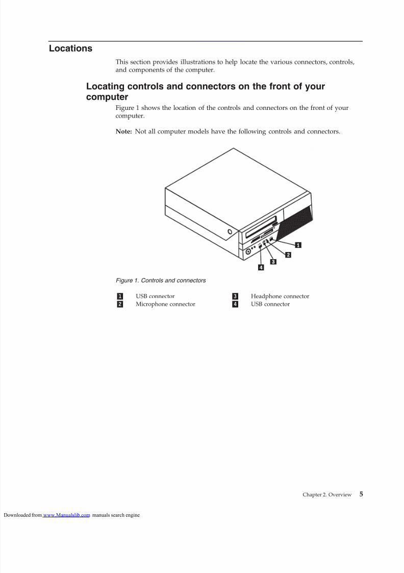
Locating controls and connectors on the front of your computer. . . . . . . . . . . . . 5Locating connectors on the rear of your computer 6Locating components . . . . . . . . . . 8Identifying parts on the system board . . . . . 9
CAUTION:Before using this manual, it is important that you read and understand all the
related safety information for this product. Refer to the ThinkCentre Safety andWarranty Guide that you received with this product for the latest safetyinformation. Reading and understanding the safety information reduces the riskof personal injury and or damage to your product.
If you no longer have a copy of the ThinkCentre Safety and Warranty Guide, you canobtain one online from the Lenovo® Support Web site at:http://www.lenovo.com/support
This guide provides information about installing and or replacing CustomerReplaceable Units (CRUs). However, this guide does not include procedures for all
parts. It is expected that cables, switches, and certain mechanical parts be replaced by trained service personnel without the need for step-by-step procedures.
Note: Use only parts provided by Lenovo.
This guide contains instructions for installing and or replacing the following parts:
v Battery
v Power supply
v Heat sink and fan assembly
v Hard disk drive
v Optical drive
v Memory modulev Adapter card
v Card reader
v Keyboard
v Mouse
Additional information resources
If you have Internet access, the most up-to-date information for your computer isavailable at:http://www.lenovo.com/support
Do not open the static-protective package containing the new part until thedefective part has been removed from the computer and you are ready to installthe new part. Static electricity, although harmless to you, can seriously damagecomputer components and parts.
When you handle parts and other computer components, take these precautions toavoid static-electricity damage:
v Limit your movement. Movement can cause static electricity to build up aroundyou.
v Always handle parts and other computer components carefully. Handle adaptercards, memory modules, system boards, and microprocessors by the edges.Never touch any exposed circuitry.
v Prevent others from touching the parts and other computer components.
v Before you replace a new part, touch the static-protective package containing thepart to a metal expansion-slot cover or other unpainted metal surface on thecomputer for at least two seconds. This reduces static electricity in the packageand your body.
v When possible, remove the new part from the static-protective packaging, andinstall it directly in the computer without setting the part down. When this isnot possible, place the static-protective package that the part came in on asmooth, level surface and place the part on it.
v Do not place the part on the computer cover or other metal surface.
4 ThinkCentre Hardware Installation and Replacement Guide
loaded from www.Manualslib.com manuals search engine
Locating connectors on the rear of your computerFigure 2 shows the location of connectors on the rear of your computer. Someconnectors on the rear of your computer are color-coded to help you determinewhere to connect the cables on your computer.
1 Serial port (some models) 9 Standard mouse connector (somemodels)
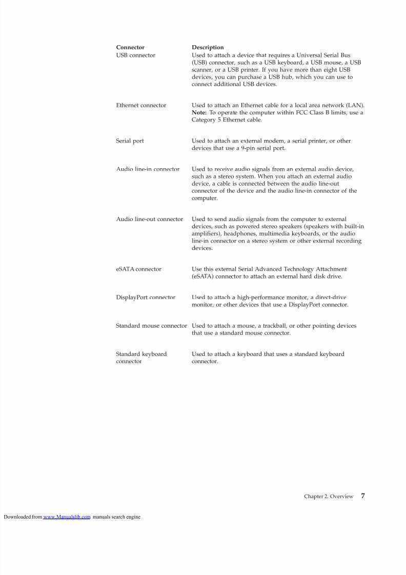
USB connector Used to attach a device that requires a Universal Serial Bus(USB) connector, such as a USB keyboard, a USB mouse, a USBscanner, or a USB printer. If you have more than eight USBdevices, you can purchase a USB hub, which you can use toconnect additional USB devices.
Ethernet connector Used to attach an Ethernet cable for a local area network (LAN).Note: To operate the computer within FCC Class B limits, use aCategory 5 Ethernet cable.
Serial port Used to attach an external modem, a serial printer, or otherdevices that use a 9-pin serial port.
Audio line-in connector Used to receive audio signals from an external audio device,such as a stereo system. When you attach an external audiodevice, a cable is connected between the audio line-outconnector of the device and the audio line-in connector of the
computer.
Audio line-out connector Used to send audio signals from the computer to externaldevices, such as powered stereo speakers (speakers with built-inamplifiers), headphones, multimedia keyboards, or the audioline-in connector on a stereo system or other external recordingdevices.
eSATA connector Use this external Serial Advanced Technology Attachment(eSATA) connector to attach an external hard disk drive.
DisplayPort connector Used to attach a high-performance monitor, a direct-drivemonitor, or other devices that use a DisplayPort connector.
Standard mouse connector Used to attach a mouse, a trackball, or other pointing devicesthat use a standard mouse connector.
Standard keyboardconnector
Used to attach a keyboard that uses a standard keyboardconnector.
Chapter 2. Overview 7
loaded from www.Manualslib.com manuals search engine
Chapter 3. Installing options and replacing hardware
This chapter provides an introduction to the features and options that are availablefor your computer. You can expand the capabilities of your computer by adding
memory modules, adapter cards, or drives. When installing an option, use theseinstructions along with the instructions that come with the option.
Attention
Do not open your computer or attempt any repair before reading the “Important safetyinformation” in the ThinkCentre Safety and Warranty Guide that came with your computer.To obtain a copy of the ThinkCentre Safety and Warranty Guide, go to:http://www.lenovo.com/support
Note: Use only parts provided by Lenovo.
Installing external optionsExternal speakers, a printer, or a scanner can be connected to your computer. Forsome external options, you must install additional software in addition to makingthe physical connection. When adding an external option, see “Locating connectorson the rear of your computer” on page 6 and “Locating controls and connectors onthe front of your computer” on page 5 to identify the required connector, and thenuse the instructions that are included with the option to help you make theconnection and install any software or device drivers that are required for theoption.
ImportantRead “Handling static-sensitive devices” on page 4 before opening thecomputer cover.
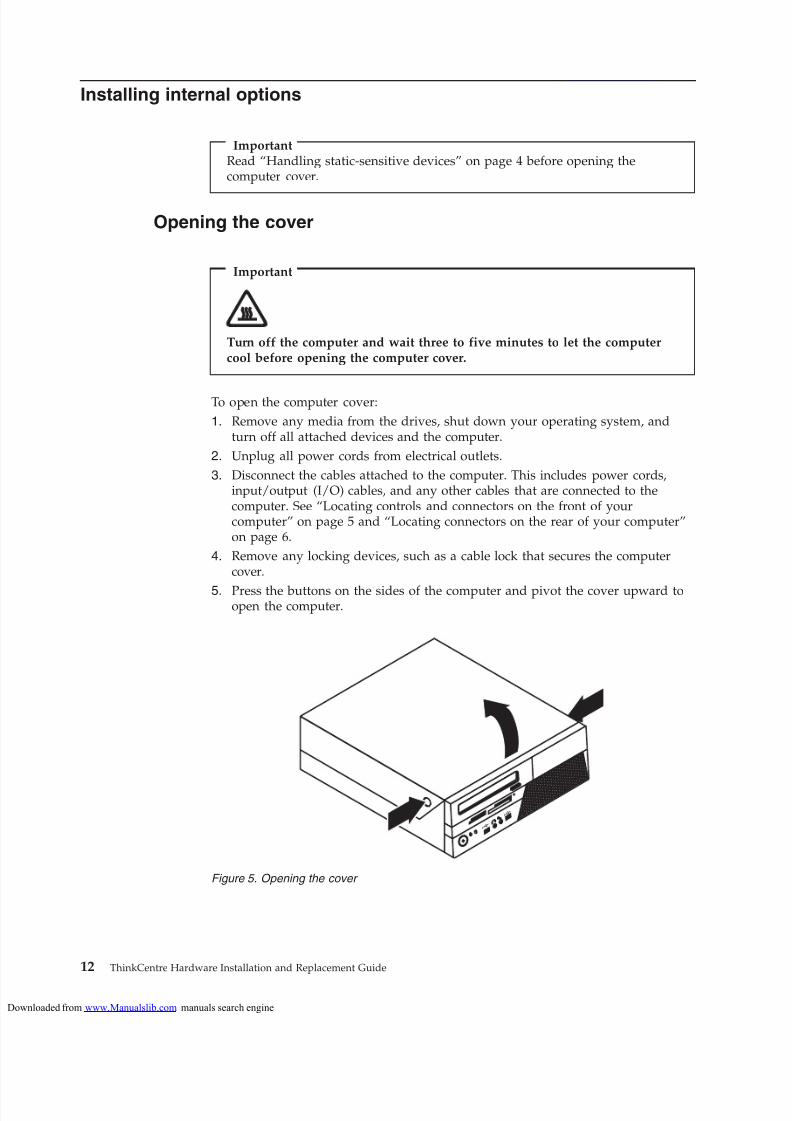
Opening the cover
Important
Turn off the computer and wait three to five minutes to let the computercool before opening the computer cover.
To open the computer cover:
1. Remove any media from the drives, shut down your operating system, andturn off all attached devices and the computer.
2. Unplug all power cords from electrical outlets.
3. Disconnect the cables attached to the computer. This includes power cords,input/output (I/O) cables, and any other cables that are connected to thecomputer. See “Locating controls and connectors on the front of yourcomputer” on page 5 and “Locating connectors on the rear of your computer”on page 6.
4. Remove any locking devices, such as a cable lock that secures the computercover.
5. Press the buttons on the sides of the computer and pivot the cover upward toopen the computer.
Figure 5. Opening the cover
12 ThinkCentre Hardware Installation and Replacement Guide
loaded from www.Manualslib.com manuals search engine
Accessing system board components and drivesTo access system board components and the drives:
1. Open the computer cover. See “Opening the cover” on page 12.
2. On some models, you might need to pivot the drive bay assembly upward andremove the hard disk drive to access the internal components. See “Replacing ahard disk drive” on page 25.
Note: Make sure you note the location of any cables that you disconnect fromthe drives or the system board.Attention: You must return the hard disk drive assembly to the latchedposition before you close the cover to prevent damage to the hard disk driveassembly.
Installing a memory moduleYour computer has four slots for installing DDR3 DIMMs (double data rate 3 dualinline memory modules) that provide up to a maximum of 8 GB of systemmemory.
When installing memory modules, use the following guidelines:
v Use 1.8 V, 240-pin DDR3 SDRAM (double data rate 3 synchronous dynamicrandom access memory).
v Use 1 GB or 2 GB memory modules in any combination up to a maximum of 8GB.
To install a memory module:
1. Open the computer cover. See “Opening the cover” on page 12.
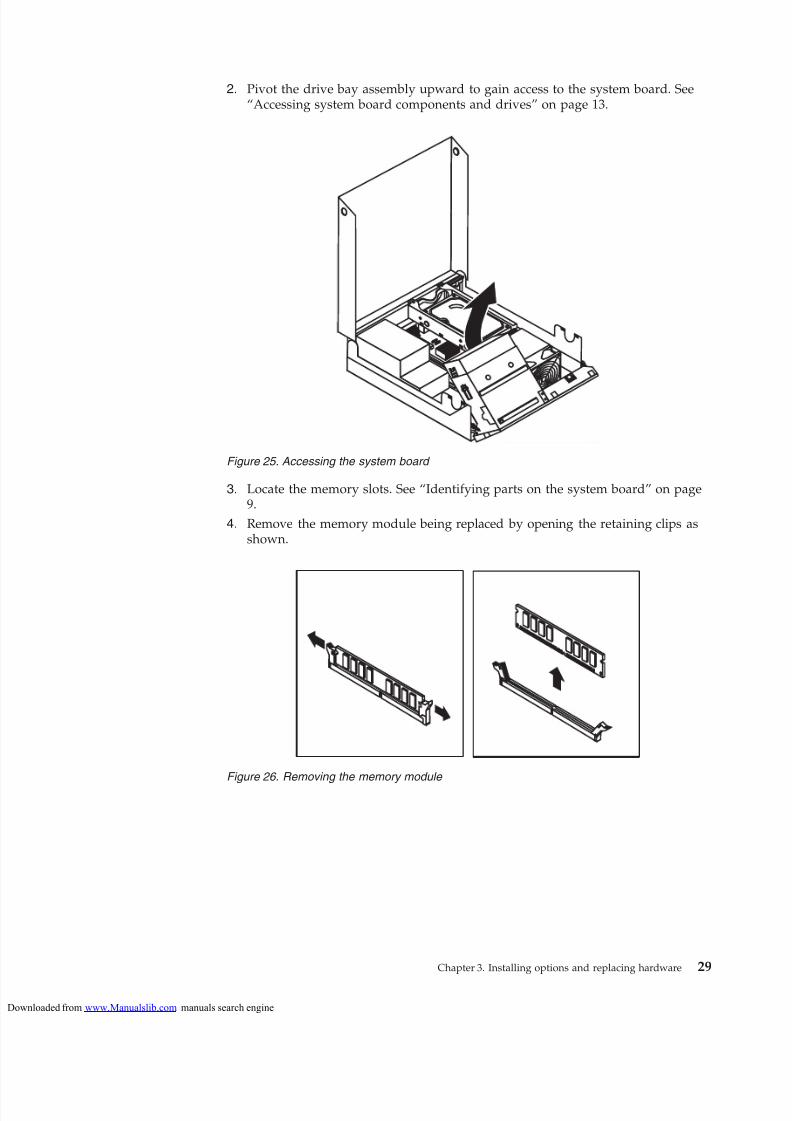
2. You might have to pivot the drive bay assembly upward to access the memoryslots. See “Accessing system board components and drives.”
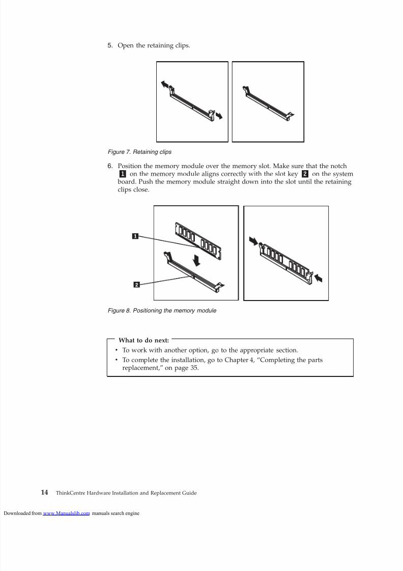
3. Remove any parts that might prevent access to the memory slots.
4. Locate the memory slots.
Figure 6. Pivoting the drive bay
Chapter 3. Installing options and replacing hardware 13
loaded from www.Manualslib.com manuals search engine
Installing an adapter cardThis section provides information and instructions for installing adapter cards.Your computer has one PCI adapter card slot and one PCI Express x16 adaptercard slot.
To install an adapter card:
1. Open the computer cover. See “Opening the cover” on page 12.2. Rotate the adapter card retainer 1 to the open position.
3. Remove the new adapter card from its static-protective package.
4. Install the adapter card 2 into the appropriate adapter card slot on the system board.
Note: The white slot is for the PCI adapter card and the black slot is for thePCI Express x16 adapter card.
5. Rotate the adapter card retainer to the closed position.
What to do next:
v To work with another option, go to the appropriate section.
v To complete the installation, go to Chapter 4, “Completing the partsreplacement,” on page 35.
Figure 9. Installing the adapter card
Chapter 3. Installing options and replacing hardware 15
loaded from www.Manualslib.com manuals search engine
Drive specificationsYour computer comes with the following factory-installed drives:v A 3.5-inch hard disk drive in bay 1v An optical drive in bay 2 (some models)
Any bay that does not have a drive installed has a static shield and bay panelinstalled.
Figure 10 shows the location of the drive bays.
The following list describes the types and size of drives that you can install in each bay:
1 Bay 1 Internal hard disk drive1.8-inch Solid State Drive (requires aUniversal Adapter Bracket, 3.5 to1.8-inch)
2 Bay 2 - Maximum height: 43.0 mm (1.7 inch) Optical drive, such as CD drive or DVDdrive (preinstalled in some models)3.5-inch hard disk drive (requires aUniversal Adapter Bracket, 5.25 to3.5-inch)*5.25-inch hard disk drive
* You can obtain a Universal Adapter Bracket, 5.25 to 3.5-inch from a localcomputer retailer or by contacting the Customer Support Center.
Figure 10. Drive bay locations
Chapter 3. Installing options and replacing hardware 17
loaded from www.Manualslib.com manuals search engine
Installing a drive in bay 2To install an optical drive or an additional hard disk drive in bay 2:
1. Open the computer cover. See “Opening the cover” on page 12.
2. Remove the metal shield from the drive bay by using a flat-blade screwdriverto gently pry it loose.
3. If you are installing a drive with accessible media, such as an optical drive,
remove the plastic panel in the bezel by squeezing the plastic tabs that securethe panel on the inside of the bezel.
Note: If you are installing a 3.5-inch hard disk drive you must use a UniversalAdapter Bracket, 5.25 to 3.5-inch. You can obtain this bracket from a localcomputer retailer or by contacting the Customer Support Center.
4. Slide the drive into the bay until it locks into position.
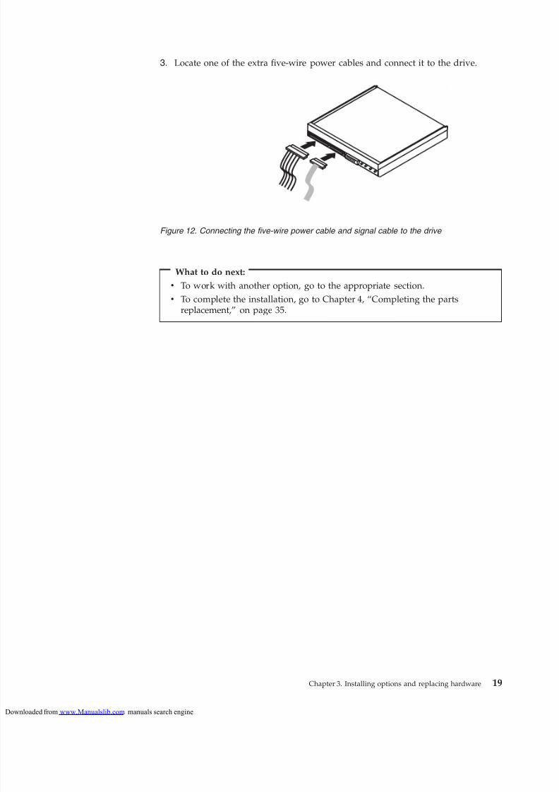
5. Pivot the drive bay assembly upward to gain access to the cable connectionsand connect the drive signal and power cables.
6. Continue at “Connecting a Serial ATA drive.”
Connecting a Serial ATA driveA serial optical drive or an additional hard disk drive can be connected to anyavailable SATA connector.
1. Locate the available SATA connector on the system board. See “Identifyingparts on the system board” on page 9.
2. Using the signal cable that came with the new drive, connect one end of thesignal cable to the drive and the other to the available SATA connector on thesystem board.
Figure 11. Installing a drive in bay 2
18 ThinkCentre Hardware Installation and Replacement Guide
loaded from www.Manualslib.com manuals search engine
Your computer has a special type of memory that maintains the date, time, andsettings for built-in features, such as parallel-port assignments (configuration). A
battery keeps this information active when you turn off the computer.
The battery normally requires no charging or maintenance throughout its life;
however, no battery lasts forever. If the battery fails, the date, time, andconfiguration information (including passwords) are lost. An error message isdisplayed when you turn on the computer.
Refer to the “Lithium battery notice” in the ThinkCentre Safety and Warranty Guidefor information about replacing and disposing of the battery.
To replace the battery:
1. Open the computer cover. See “Opening the cover” on page 12.
2. Access the system board. See “Accessing system board components and drives”on page 13.
3. Locate the battery. See “Identifying parts on the system board” on page 9.
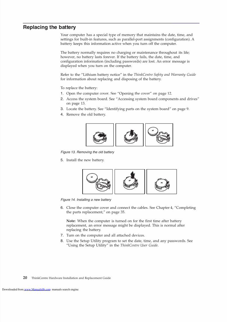
4. Remove the old battery.
5. Install the new battery.
6. Close the computer cover and connect the cables. See Chapter 4, “Completingthe parts replacement,” on page 35.
Note: When the computer is turned on for the first time after battery
replacement, an error message might be displayed. This is normal afterreplacing the battery.
7. Turn on the computer and all attached devices.
8. Use the Setup Utility program to set the date, time, and any passwords. See“Using the Setup Utility” in the ThinkCentre User Guide.
Figure 13. Removing the old battery
Figure 14. Installing a new battery
20 ThinkCentre Hardware Installation and Replacement Guide
loaded from www.Manualslib.com manuals search engine
Do not open your computer or attempt any repair before reading the “Important safetyinformation” in the ThinkCentre Safety and Warranty Guide that came with your computer.To obtain a copy of the ThinkCentre Safety and Warranty Guide, go to:
http://www.lenovo.com/support
To replace the power supply:
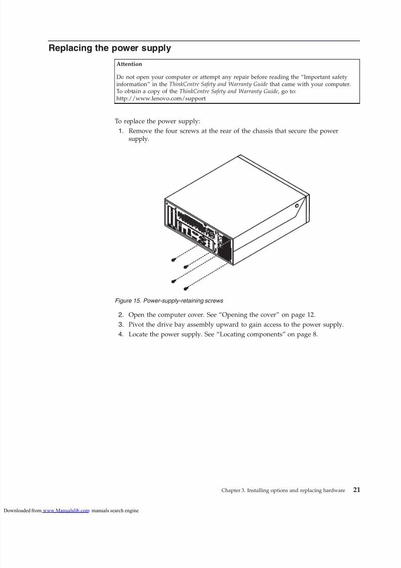
1. Remove the four screws at the rear of the chassis that secure the powersupply.
2. Open the computer cover. See “Opening the cover” on page 12.
3. Pivot the drive bay assembly upward to gain access to the power supply.
4. Locate the power supply. See “Locating components” on page 8.
Figure 15. Power-supply-retaining screws
Chapter 3. Installing options and replacing hardware 21
loaded from www.Manualslib.com manuals search engine
9. Install and tighten the four screws at the rear of the chassis to secure thepower supply.
10. Check the position of the voltage-selection switch on the rear of the computer.Use a ballpoint pen to slide the switch, if necessary.
Note: Some computers do not have a voltage-selection switch. Thesecomputers automatically control the voltage.
v If the voltage supply range is 100–127 V AC, set the switch to 115 V.
v If the voltage supply range is 200–240 V AC, set the switch to 230 V.
11. Reconnect all the power supply cables to the drives and the system board.
12. Go to Chapter 4, “Completing the parts replacement,” on page 35.
Replacing the heat sink and fan assembly
Attention
Do not open your computer or attempt any repair before reading the “Important safety
information” in the ThinkCentre Safety and Warranty Guide that came with your computer.To obtain a copy of the ThinkCentre Safety and Warranty Guide, go to:http://www.lenovo.com/support
This section provides instructions on how to replace the heat sink and fanassembly.
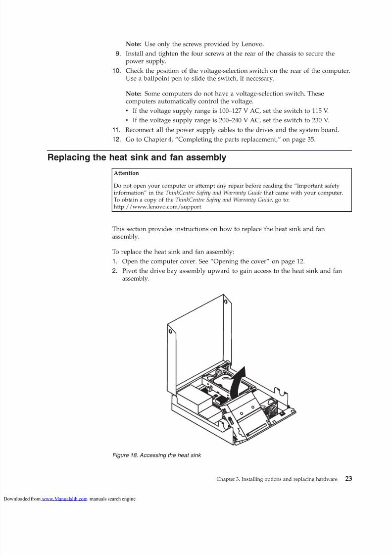
To replace the heat sink and fan assembly:
1. Open the computer cover. See “Opening the cover” on page 12.
2. Pivot the drive bay assembly upward to gain access to the heat sink and fanassembly.
Figure 18. Accessing the heat sink
Chapter 3. Installing options and replacing hardware 23
loaded from www.Manualslib.com manuals search engine
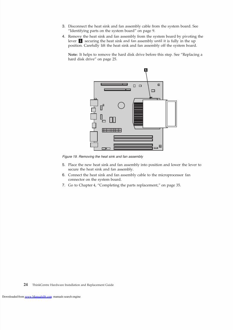
3. Disconnect the heat sink and fan assembly cable from the system board. See“Identifying parts on the system board” on page 9.
4. Remove the heat sink and fan assembly from the system board by pivoting thelever 1 securing the heat sink and fan assembly until it is fully in the upposition. Carefully lift the heat sink and fan assembly off the system board.
Note: It helps to remove the hard disk drive before this step. See “Replacing a
hard disk drive” on page 25.
5. Place the new heat sink and fan assembly into position and lower the lever tosecure the heat sink and fan assembly.
6. Connect the heat sink and fan assembly cable to the microprocessor fanconnector on the system board.
7. Go to Chapter 4, “Completing the parts replacement,” on page 35.
Figure 19. Removing the heat sink and fan assembly
24 ThinkCentre Hardware Installation and Replacement Guide
loaded from www.Manualslib.com manuals search engine
Do not open your computer or attempt any repair before reading the “Important safetyinformation” in the ThinkCentre Safety and Warranty Guide that came with your computer.To obtain a copy of the ThinkCentre Safety and Warranty Guide, go to:
http://www.lenovo.com/support
This section provides instructions on how to replace the hard disk drive.
ImportantWhen you receive a new hard disk drive, you also receive a set of ProductRecovery discs. The set of Product Recovery discs will enable you to restore thecontents of the hard disk drive to the same state as when your computer wasoriginally shipped from the factory. For more information on recoveringfactory-installed software, refer to “Recovering software” in your ThinkCentreUser Guide.
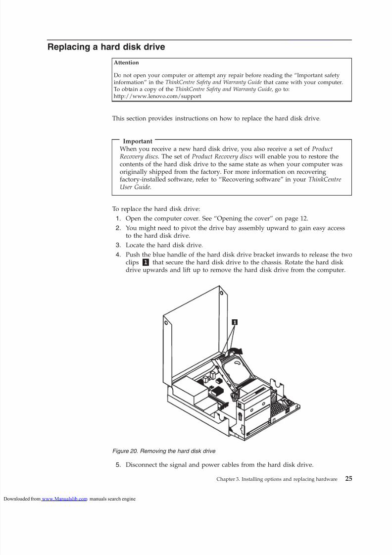
To replace the hard disk drive:
1. Open the computer cover. See “Opening the cover” on page 12.
2. You might need to pivot the drive bay assembly upward to gain easy accessto the hard disk drive.
3. Locate the hard disk drive.
4. Push the blue handle of the hard disk drive bracket inwards to release the twoclips 1 that secure the hard disk drive to the chassis. Rotate the hard diskdrive upwards and lift up to remove the hard disk drive from the computer.
5. Disconnect the signal and power cables from the hard disk drive.
Figure 20. Removing the hard disk drive
Chapter 3. Installing options and replacing hardware 25
loaded from www.Manualslib.com manuals search engine
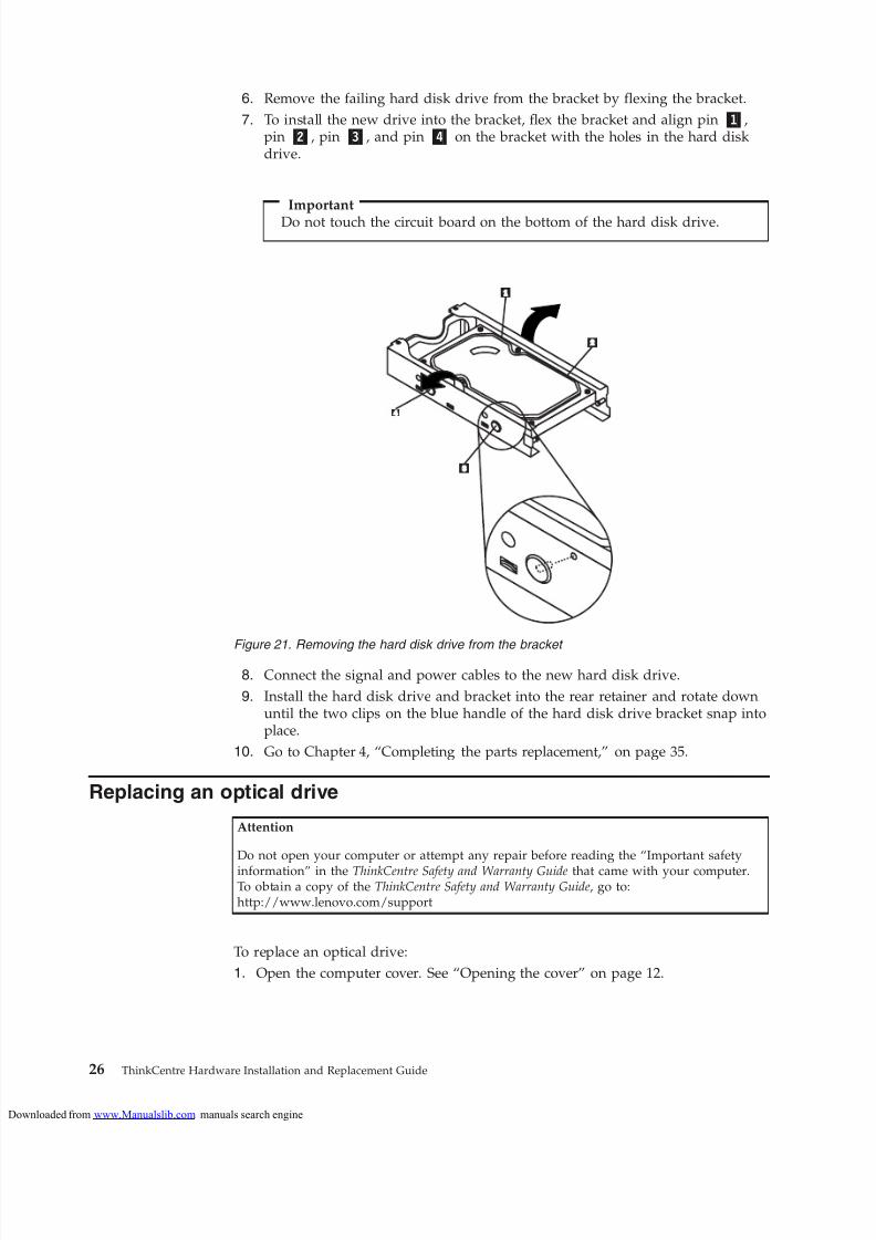
6. Remove the failing hard disk drive from the bracket by flexing the bracket.
7. To install the new drive into the bracket, flex the bracket and align pin 1,pin 2, pin 3, and pin 4 on the bracket with the holes in the hard diskdrive.
Important
Do not touch the circuit board on the bottom of the hard disk drive.
8. Connect the signal and power cables to the new hard disk drive.
9. Install the hard disk drive and bracket into the rear retainer and rotate downuntil the two clips on the blue handle of the hard disk drive bracket snap intoplace.
10. Go to Chapter 4, “Completing the parts replacement,” on page 35.
Replacing an optical drive
Attention
Do not open your computer or attempt any repair before reading the “Important safety
information” in the ThinkCentre Safety and Warranty Guide that came with your computer.To obtain a copy of the ThinkCentre Safety and Warranty Guide, go to:http://www.lenovo.com/support
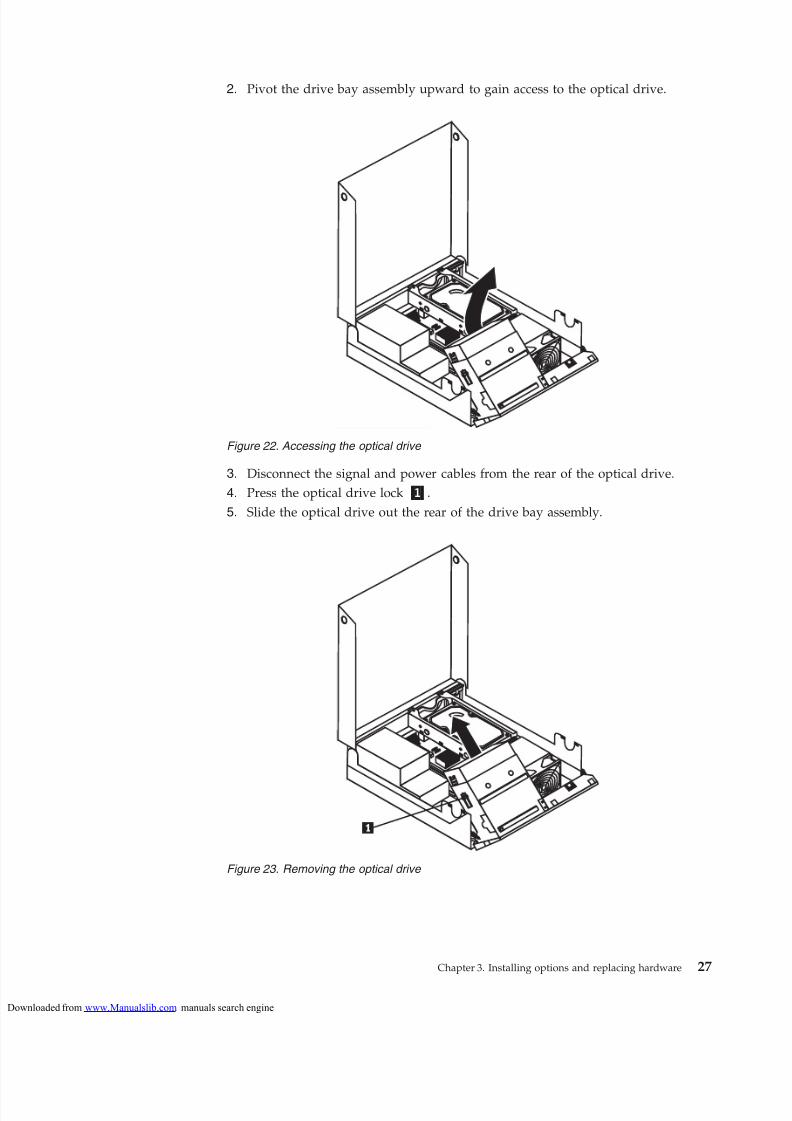
To replace an optical drive:
1. Open the computer cover. See “Opening the cover” on page 12.
Figure 21. Removing the hard disk drive from the bracket
26 ThinkCentre Hardware Installation and Replacement Guide
loaded from www.Manualslib.com manuals search engine
6. Install the new optical drive into the bay until it snaps into position.
7. Connect the signal and power cables to the rear of the optical drive.
8. Go to Chapter 4, “Completing the parts replacement,” on page 35.
Replacing a memory module
Attention
Do not open your computer or attempt any repair before reading the “Important safetyinformation” in the ThinkCentre Safety and Warranty Guide that came with your computer.To obtain a copy of the ThinkCentre Safety and Warranty Guide, go to:http://www.lenovo.com/support
This section provides instructions on how to replace a memory module. Yourcomputer can support a maximum of four memory modules.
1. Open the computer cover. See “Opening the cover” on page 12.
Figure 24. Installing the optical drive
28 ThinkCentre Hardware Installation and Replacement Guide
loaded from www.Manualslib.com manuals search engine
2. Rotate the adapter card retainer 1 to the open position to remove the failingadapter card.
3. Remove the failing adapter card out of the chassis.
4. Remove the new adapter card from its static-protective package.
5. Install the new adapter card 2 into the adapter card slot.
6. Ensure the adapter card is fully seated into the adapter card slot.
7. Close the adapter card retainer.
8. Go to Chapter 4, “Completing the parts replacement,” on page 35.
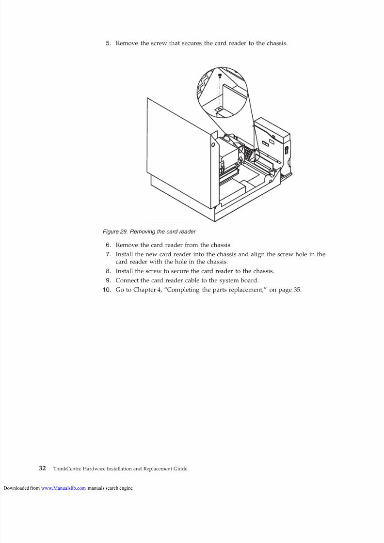
Replacing the card reader
Attention
Do not open your computer or attempt any repair before reading the “Important safetyinformation” in the ThinkCentre Safety and Warranty Guide that came with your computer.To obtain a copy of the ThinkCentre Safety and Warranty Guide, go to:http://www.lenovo.com/support
This section provides instructions on how to replace the card reader.
1. Open the computer cover. See “Opening the cover” on page 12.
2. Pivot the drive bay assembly upward to gain access to the card reader.
3. Locate the card reader.
4. Disconnect the card reader cable from the front USB connector on the system board. See “Identifying parts on the system board” on page 9.
Note: Make sure you note the location of the cable when you disconnect thecable from the system board.
Figure 28. Installing an adapter card
Chapter 3. Installing options and replacing hardware 31
loaded from www.Manualslib.com manuals search engine
Do not open your computer or attempt any repair before reading the “Important safetyinformation” in the ThinkCentre Safety and Warranty Guide that came with your computer.To obtain a copy of the ThinkCentre Safety and Warranty Guide, go to:
http://www.lenovo.com/support
This section provides instructions on how to replace a keyboard.
1. Remove any media from the drives, shut down your operating system, andturn off all attached devices and the computer.
2. Unplug all power cords from electrical outlets.
3. Locate the keyboard connector.
Note: Your keyboard might be connected to a standard keyboard connector 1or a USB connector 2. Depending on where your keyboard is connected, see“Locating connectors on the rear of your computer” on page 6 or “Locating
controls and connectors on the front of your computer” on page 5.
4. Disconnect the failing keyboard cable from the computer.
5. Connect the new keyboard to the appropriate connector on the computer.
6. Go to Chapter 4, “Completing the parts replacement,” on page 35.
Replacing the mouse
Attention
Do not open your computer or attempt any repair before reading the “Important safetyinformation” in the ThinkCentre Safety and Warranty Guide that came with your computer.
To obtain a copy of the ThinkCentre Safety and Warranty Guide, go to:http://www.lenovo.com/support
This section provides instructions on how to replace a mouse.
1. Remove any media from the drives, shut down your operating system, andturn off all attached devices and the computer.
2. Unplug all power cords from electrical outlets.
3. Locate the connector for the mouse.
Figure 30. Keyboard connectors
Chapter 3. Installing options and replacing hardware 33
loaded from www.Manualslib.com manuals search engine
Note: Your mouse might be connected to a standard mouse connector 1 or aUSB connector 2. Depending on where your mouse is connected, see“Locating connectors on the rear of your computer” on page 6 or “Locatingcontrols and connectors on the front of your computer” on page 5.
4. Disconnect the failing mouse cable from the computer.
5. Connect the new mouse cable to the appropriate connector on the computer.6. Go to Chapter 4, “Completing the parts replacement,” on page 35.
Figure 31. Mouse connectors
34 ThinkCentre Hardware Installation and Replacement Guide
loaded from www.Manualslib.com manuals search engine
After completing all parts replacements, you need to close the cover and reconnectcables, such as power cords. Depending on the parts replaced, you might need to
confirm the updated information in the Setup Utility program. Refer to “Using theSetup Utility” in the ThinkCentre User Guide for this product.
To complete the parts replacement:
1. Ensure that all components have been reassembled correctly and that no toolsor loose screws are left inside your computer. See “Locating components” onpage 8 for the location of various components.
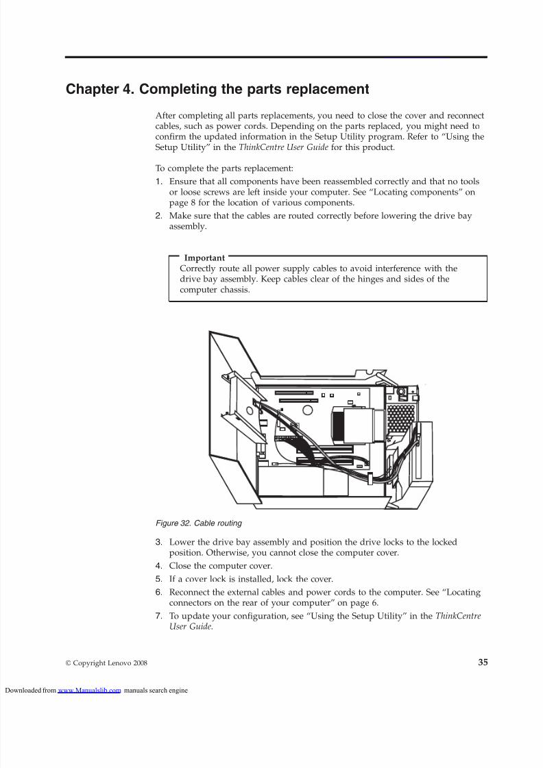
2. Make sure that the cables are routed correctly before lowering the drive bayassembly.
Important
Correctly route all power supply cables to avoid interference with thedrive bay assembly. Keep cables clear of the hinges and sides of thecomputer chassis.
3. Lower the drive bay assembly and position the drive locks to the lockedposition. Otherwise, you cannot close the computer cover.
4. Close the computer cover.
5. If a cover lock is installed, lock the cover.
6. Reconnect the external cables and power cords to the computer. See “Locatingconnectors on the rear of your computer” on page 6.
7. To update your configuration, see “Using the Setup Utility” in the ThinkCentreUser Guide.
Note: In most areas of the world, Lenovo requires the return of the defective CRU.Information about this will come with the CRU or will come a few days after theCRU arrives.
Obtaining device drivers
You can obtain device drivers for operating systems that are not preinstalled at
http://www.lenovo.com/support. Installation instructions are provided in readmefiles with the device-driver files.
36 ThinkCentre Hardware Installation and Replacement Guide
loaded from www.Manualslib.com manuals search engine
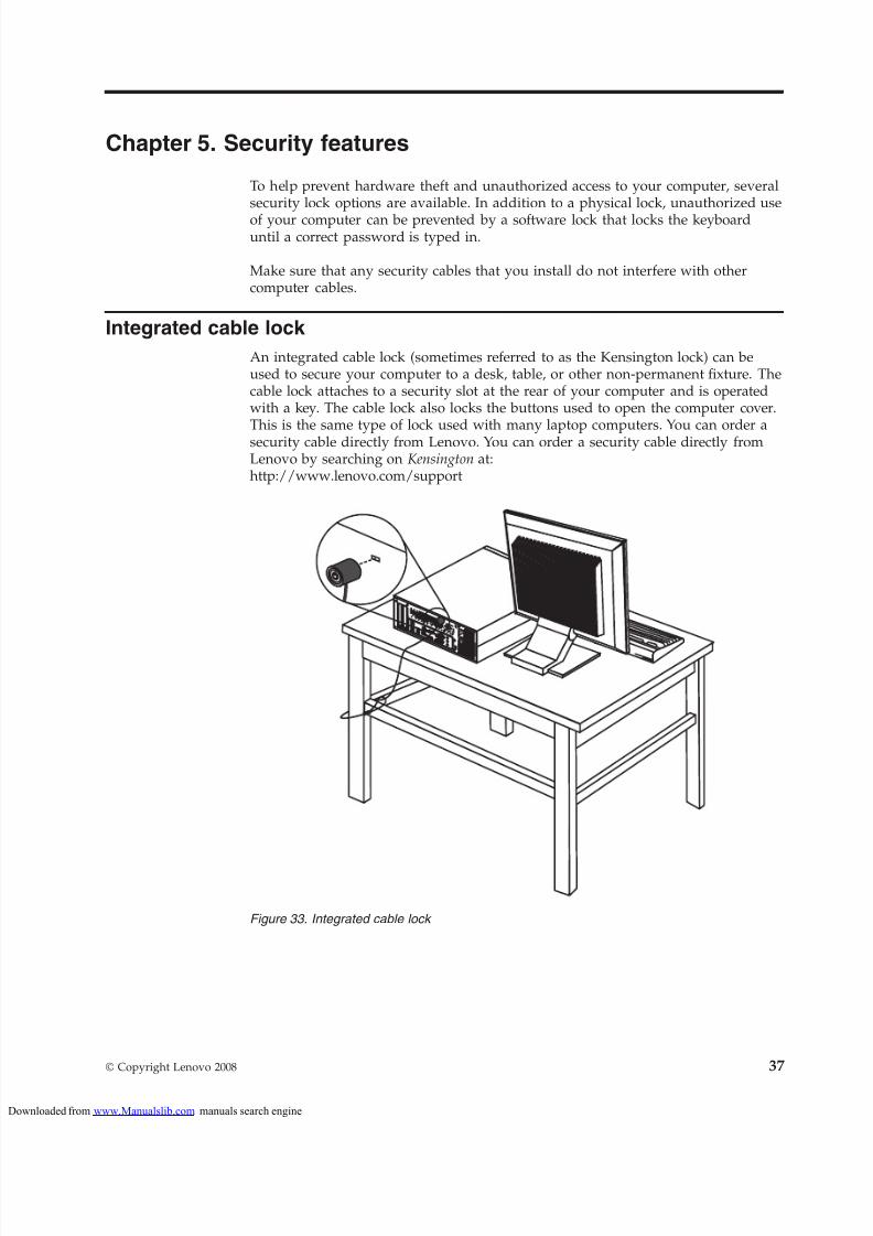
To help prevent hardware theft and unauthorized access to your computer, severalsecurity lock options are available. In addition to a physical lock, unauthorized use
of your computer can be prevented by a software lock that locks the keyboarduntil a correct password is typed in.
Make sure that any security cables that you install do not interfere with othercomputer cables.
Integrated cable lock
An integrated cable lock (sometimes referred to as the Kensington lock) can beused to secure your computer to a desk, table, or other non-permanent fixture. Thecable lock attaches to a security slot at the rear of your computer and is operatedwith a key. The cable lock also locks the buttons used to open the computer cover.
This is the same type of lock used with many laptop computers. You can order asecurity cable directly from Lenovo. You can order a security cable directly fromLenovo by searching on Kensington at:http://www.lenovo.com/support
To deter unauthorized use of your computer, you can use the Setup Utilityprogram to set a password. When you turn on your computer, you are promptedto type the password to unlock the keyboard for normal use.
Erasing a lost or forgotten password (clearing CMOS)This section contains instructions on erasing some lost or forgotten passwords,such as a user password. For more information about lost or forgotten passwords,go to the ThinkVantage® Productivity Center program.
To erase a lost or forgotten password:
1. Open the computer cover. See “Opening the cover” on page 12.
2. Access the system board. See “Accessing system board components anddrives” on page 13.
Note: You must remove the hard disk drive to gain access to the ClearCMOS/Recovery jumper.
3. Locate the Clear CMOS/Recovery jumper on the system board. See“Identifying parts on the system board” on page 9.
4. Move the jumper from the standard position (pin 1 and pin 2) to themaintenance or configure position (pin 2 and pin 3).
5. Reinstall the hard disk drive.
6. Lower the drive bay assembly and reconnect any cables that weredisconnected.
7. Close the computer cover and connect the power cord. See Chapter 4,“Completing the parts replacement,” on page 35.
8. Restart the computer and leave it on for approximately 10 seconds. Turn off the computer by holding the power switch for approximately 5 seconds. The
computer will turn off.9. Repeat step 1 through step 3 on page 38.
10. Move the Clear CMOS/Recovery jumper back to the standard position (pin 1and pin 2).
11. Reinstall the hard disk drive if removed.
12. Close the computer cover and connect the power cord. See Chapter 4,“Completing the parts replacement,” on page 35.
38 ThinkCentre Hardware Installation and Replacement Guide
loaded from www.Manualslib.com manuals search engine
Lenovo may not offer the products, services, or features discussed in thisdocument in all countries. Consult your local Lenovo representative for
information on the products and services currently available in your area. Anyreference to a Lenovo product, program, or service is not intended to state orimply that only that Lenovo product, program, or service may be used. Anyfunctionally equivalent product, program, or service that does not infringe anyLenovo intellectual property right may be used instead. However, it is the user’sresponsibility to evaluate and verify the operation of any other product, program,or service.
Lenovo may have patents or pending patent applications covering subject matterdescribed in this document. The furnishing of this document does not give youany license to these patents. You can send license inquiries, in writing, to:
Lenovo (United States), Inc.1009 Think Place - Building One Morrisville, NC 27560U.S.A. Attention: Lenovo Director of Licensing
LENOVO PROVIDES THIS PUBLICATION “AS IS” WITHOUT WARRANTY OFANY KIND, EITHER EXPRESS OR IMPLIED, INCLUDING, BUT NOT LIMITEDTO, THE IMPLIED WARRANTIES OF NON-INFRINGEMENT,MERCHANTABILITY OR FITNESS FOR A PARTICULAR PURPOSE. Some
jurisdictions do not allow disclaimer of express or implied warranties in certaintransactions, therefore, this statement may not apply to you.
This information could include technical inaccuracies or typographical errors.
Changes are periodically made to the information herein; these changes will beincorporated in new editions of the publication. Lenovo may make improvementsand/or changes in the product(s) and/or the program(s) described in thispublication at any time without notice.
The products described in this document are not intended for use in implantationor other life support applications where malfunction may result in injury or deathto persons. The information contained in this document does not affect or changeLenovo product specifications or warranties. Nothing in this document shalloperate as an express or implied license or indemnity under the intellectualproperty rights of Lenovo or third parties. All information contained in thisdocument was obtained in specific environments and is presented as anillustration. The result obtained in other operating environments may vary.
Lenovo may use or distribute any of the information you supply in any way it believes appropriate without incurring any obligation to you.
Any references in this publication to non-Lenovo Web sites are provided forconvenience only and do not in any manner serve as an endorsement of those Websites. The materials at those Web sites are not part of the materials for this Lenovoproduct, and use of those Web sites is at your own risk.
Any performance data contained herein was determined in a controlledenvironment. Therefore, the result obtained in other operating environments may
vary significantly. Some measurements may have been made on development-levelsystems and there is no guarantee that these measurements will be the same ongenerally available systems. Furthermore, some measurements may have beenestimated through extrapolation. Actual results may vary. Users of this documentshould verify the applicable data for their specific environment.
Television output noticeThe following notice applies to models that have the factory-installedtelevision-output feature.
This product incorporates copyright protection technology that is protected bymethod claims of certain U.S. patents and other intellectual property rights owned
by Macrovision Corporation and other rights owners. Use of this copyrightprotection technology must be authorized by Macrovision Corporation, and isintended for home and other limited viewing uses only unless otherwiseauthorized by Macrovision Corporation. Reverse engineering or disassembly isprohibited.
TrademarksThe following terms are trademarks of Lenovo in the United States, othercountries, or both:
LenovoThe Lenovo logoThinkCentreThinkVantage
Other company, product, or service names may be trademarks or service marks of others.
40 ThinkCentre Hardware Installation and Replacement Guide
loaded from www.Manualslib.com manuals search engine