NASA CR-66639 (Thiokol No. U-68-20A) THEORETICAL STUDY OF THE BALLISTICS AND HEAT TRANSFER IN SPINNING SOLID PROPELLANT ROCKET MOTORS By R, Harold Whitesides, Jr, and B. Keith Hodge August 1968 Distribution of this report is provided in the interest of information exchange. Responsibility for the contents resides in the author or organization that prepared it. Prepared under Contract No, NAS 1-7034 by THIOKOL CHEMICAL CORPORATION HUNTSVILLE DIVISION Huntsville, Ala. for NATIONAL AERONAUTICS AND SPACE ADMINISTRATION https://ntrs.nasa.gov/search.jsp?R=19680021833 2020-01-01T12:46:38+00:00Z
Transcript
NASA CR-66639
(Thiokol No. U-68-20A)
THEORETICAL STUDY OF THE BALLISTICS AND HEAT TRANSFER IN
SPINNING SOLID PROPELLANT ROCKET MOTORS
By R, Harold Whitesides, Jr, and B. Keith Hodge
August 1968
Distribution of this report is provided in the interest of
information exchange. Responsibility for the contents
resides in the author or organization that prepared it.
This program was conducted for the Langley Research Center of the
National Aeronautics and Space Administration by the Huntsville Division
of Thiokol Chemical Corporation under Contract NAS 1-7034. Mr. G.
Burton Northam was Technical Monitor for the contract. This work was
performed during the period April 3, 1967 through July 3, 1968.
R. Harold Whitesides, Jr. was the Principal Investigator for
this program. B. Keith Hodge performed the gas dynamics and burning
rate model studies. W. I. Dale, Jr. was Program Manager for this
contract.
Acknowledgement is due Dr. R. L. Glick for several consultations
concerning the burning rate models and L. H. Caveny for giving direction
to and initiating the program studies.
This report has been assigned the Thiokol internal number U-68-20A.
iii
t,_ECEDIN'2 'G PAGE BLANK NOT FILMED.
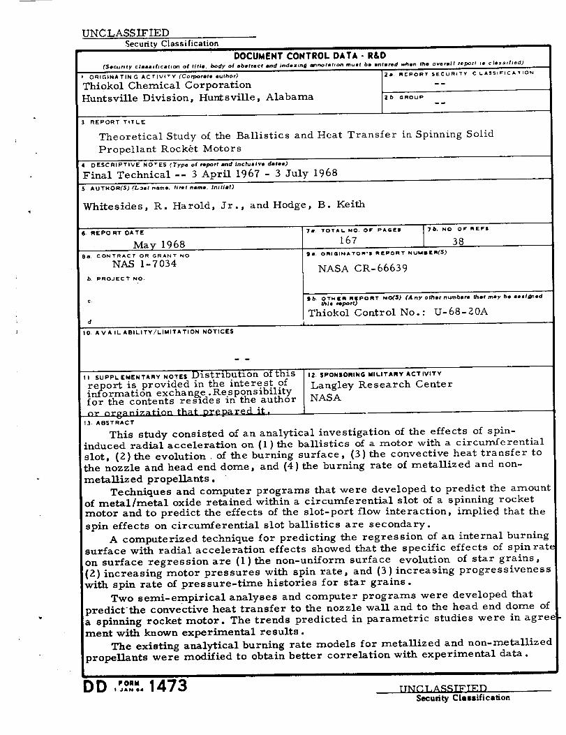
A BS TRA C T
This study consisted of an analytical investigation of the effects of spin-
induced radial acceleration on (1) the ballistics of a motor with a circum-
ferential slot, (2)the evolution of the burning surface, (3)the convective
heat transfer to the nozzle and head-end dome, and (4) the burning rate of
metallized and non-metallized propellants.
Techniques and computer programs that were developed to predict the
amount of metal/metal oxide retained within a circumferential slot of a
spinning rocket motor and to predict the effects of the slot-port flow
interaction, implied that the spin effects on circumferential slot ballistics
are secondary.
A computerized technique for predicting the regression of an internal
burning surface with radial acceleration effects showed that the specific
effects of spin rate on surface regression are (1)the non-uniform surface
evolution of star grains, (2)increasing motor pressures with spin rate,
and (3)increasing progressiveness with spin rate of pressure-time histories
for star grains.
Two semi-empirical analyses and computer programs were developed
that predict" the convective heat transfer to the nozzle wall and to the head-
end dome of a spinning rocket motor. The trends predicted in parametric
studies were in agreement with known experimental results.
The existing analytical burning rate models for metallized and non-
metallized propellants were modified to obtain better correlation with
experimental data.
V
PP,ECEDING PAC_: E;,-,_r'_- NOT FILi\'_L.'.
CONTENTS
PREFACE
ABSTRACT
NOMENCLA TURE
S UMMARY
INTRODUCTION
ANALYSIS OF FLOW IN CIRCUMFERENTIAL SLOTS WITH
SPIN EFFECTS
Introduction
Metal/Metal Oxide Retention
Flow Field
Particle DynamicsSlot- Port Flow Interaction
Conclusions
SURFACE REGRESSION ANALYSIS
Introduction
Burning Rate Function
Surface Regression Technique
Results of Regression AnalysisConclusions
THEORETICAL HEAT TRANSFER STUDY
Nozzle Heat Transfer
Introduction
Approach Justification
ApproachFormulation
Results of Nozzle Heat Transfer Analysis
Head End Dome Heat Transfer
Introduction
Analysis
Results of Analysis
Conclusions
EFFECT OF ACCELERATION ON BURNING RATE
General
Metallized Propellant
Non- Metalliz ed Propellant
Conclusions
Burning Rate Data
Page
iii
V
xi
1
3
5
5
6
6
l?
32
41
43
43
44
49
53
59
61
61
61
61
6%65
69
78
78
79
8Z
87
91
91
91
103
12-I
123
vii
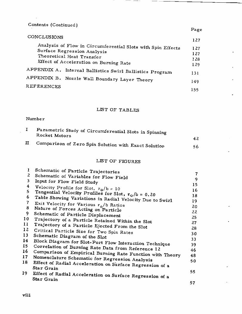
Contents (Continued)
CONCLUSIONS
Analysis of Flow in Circumferential Slots with Spin Effects
Surface Regression Analysis
Theoretical Heat Transfer
Effect of Acceleration on Burning Rate
APPENDIX A. Internal Ballistics Swirl Ballistics Program
APPENDIX B. Nozzle Wall Boundary Layer Theory
REFERENCES
Page
I27
127
127
128
129
131
149
155
LIST OF TABLES
Numb e r
I Parametric Study of Circumferential Slots in Spinning
Rocket Motors
II Comparison of Zero Spin Solution with Exact SolutioD
42
56
LIST OF FIGURES
I Schematic of Particle Trajectories2 Schematic of Variables for Flow Field
3 Input for Flow Field Study
4 Velocity Profile for Slot, ro/b = I05 Tangential Velocity Profiles for Slot, ro/b = 0.20
6 Table Showing Variations in Radial Velocity Due to Swirl
7 Ex{t Velocity for Various ro/b Ratios8 Nature of Forces Acting on Particle
9 Schematic of Particle Displacement
10 Trajectory of a Particle Retained Within the Slot
11 Trajectory of a Particle Ejected From the Slot
12 Critical Particle Size for Two Spin Rates
13 Schematic Diagram of the Slot
14 Block Diagram for Slot-Port Flow Interaction Technique
15 Correlation of Burning Rate Data from Reference 12
16 Comparison of Empirical Burning Rate Function with Theory
17 Nomenclature Schematic for Regression Analysis
18 Effect of Radial Acceleration on Shrface Regression of aStar Grain
19 Effect of Radial Acceleration on Surface Regression of a
Star Grain
7
9
15
16
18
19
Z0
22
25
27
Z8
30
33
3946
48
50
55
57
viii
List of Figures (Continued)
Number
20
21
22
23
24
25
26
27
28
29
3O
31
32
33
34
35
36
37
38
39
4O
41
42
43
44
45
46
Effect of R_dial Acceleration on Surface Regression of aStar Grain
The Effect of Spin Rate on Pressure-Time History
Effect of Spin Rate on Nozzle Heat Transfer CoefficientP r ofile s
Effect of Spin Rate on Nozzle Heat Flux
Effect of Spin Rate on Nozzle Throat Heat TransferCoefficient
Effect of Spin Rate on Velocity Components
Effect of Spin Rate on Throat Nusselt Number Ratio
Effect of Port to Throat Radius Ratio on Throat Nusselt
Number Ratio
Effect of Spin Rate on Nusselt Number Ratio Profile
Effect of Spin Rate on Heat Flux
Effect of Spin Rate on Nusselt Number Profile
Effect of Spin Rate on Core Radius
Effect of Spin Rate on Maximum Nusselt Number
Effect of Port Radius on Maximum Nusselt Number
Analytical Model for Particle Burning
Functional Dependence of 8 on Acceleration
Particle Retention Criteria
Comparison of Burning Rate Models
Free-Body Diagram of Particles Evolved from DifferentSides of the Pit
Effect of the Direction of Acceleration Force on the
Maximum Burning Rate Ratio
_/8 max Versus Acceleration for Several Compositions
Schematic of Mathematical Model for Non-Metallized
Propellants
A Comparison of the Drag Coefficients of a Sphere and
a Disc
GDFM for Low Acceleration Level
Schematic of Proposed Stratified Combustion Model
at and n for Metallized PBAN and CTPB Propellants
at and n for Non-Metallized PBAN Propellants
Page
58
60
71
72
74
75
76
76
77
84
85
86
88
89
93
96
99
101
102
104
105
107
113
115
I17
124
125
ix
F) 41Pt,,ECEDI_G PAGE BLANK NOT FILMED.
NOMENCLATURE
a
A
radial acceleration, _2 R/g
nozzle flow area
o
b
Co
cP
AC
GD
C*
d
D
F
go
G..
13
h
hD
H
k
K
L
v
slot width
sonic velocity, total conditions
specific heat, constant pressure
concentration diffe rence
drag coefficient
characteristic velocity
port diameter, particle diameter
nozzle diameter, local
force on particle
gravitational constant
influence coefficient
heat transfer coefficient
diffusion coefficient
enthalpy
gas therrr.al conductivity
vortex strength constant
characteristic length of fuel vapor pocket
mass flow rate
M Mach number
MM moment of momentum
xi
Mwt
n
N
NS
P
r
r b
r/r0
R
Rg
S
S
As
t
T
U
V
W
Wm
W
z
molecular weight of gases
burning rate exponent, r b = c_ pn
number of walls
number of pits per unit area
static pressure
radial coordinate
burning rate
a/rb)a = 0 -- burning rate ratiorb_
nozzle radius, port radius
gas constant, R [M wt
universal gas constant
distance along grain
particle surface area
distance traveled in time, At
time
temperature
axial velocity of gas
total relative velocity
tangential velocity of gases
percent aluminum content of propellant
relative tangential velocity component
axial coordinate
burning rate coefficient, r b = _ pn
xii
5r
9
kg
A
/a
go
P
¢
Gr
Nu
Pr
Re
Se
Sh
swirl strength
pitting parameter = (N
ratio of specific heats
17r dZ)" cos
thickness of gas phase reaction zone
dimensionless radial coordinate, r/rc
tangential coordinate
the rmal conductivity
volume of fuel vapor pocket
dynamic viscosity
radius ratio
density
variance in a log normal distribution
angle between surface normal and acceleration vector
swirl function defined by equation (A1 0a.)
motor spin rate
Grashof number, a _ p dry 3 / Zg
Nusselt number, hD/k
Prandtl number, .c D]kP
Reynolds number, VD p/D
Schmidt number, D] p D
Sherwood number, h D d'fv /Dg
xiii
Subscripts:
adw
B
c
D
f
fv
g
inc
M
0
OX
P
r
s
t
ts
w
z
Q
1
2
2s
Zp
ls
xiv
adiabatic wall
buoyant
core
drag
film
fuel vapor
gas
incompressible
metal particle
port, zero- spin conditions
oxidiz er
propellant
radial
surface, Spin
total
total condition with spin
wall
axial
tangential
one- dimen sional
two-dimensional
slot flow at station 2
axial flow at station Z.
slot flow at station 1
Subscripts:
Ip
3
(Cont'd)
axial flow at station 1
station 3
Super s c ripts:
!
throat
dimensionless variable
weight mean
XV
THEORETICAL STUDY OF THE BALLISTICS AND HEAT TRANSFER IN
SPINNING SOLID PROPELLANT ROCKET MOTORS
By R. Harold Whitesides, Jr. and B. Keith Hodge
Thiokol Chemical Corporation
Huntsville Division
SUMMARY
This study consisted of an analytical investigation of the effects of
spin-induced radial acceleration on (1) the ballistics of a motor with a cir-
cumferential slot, (Z) the evolution of the burning surface, (3) the convec-
tive heat transfer to the nozzle and head end dome, and (4) the burning rate
of metalliz ed and non-metalliz ed propellants.
Techniques were developed to predict the amount of metal/metal
oxide retained within a circumferential slot of a spinning rocket motor and
to predict the ballistic effects of a circumferential slot in a spinning rocket
motor. Two computer programs were written using the techniques devel-
oped. The study of metal/metal oxide retention showed that particles couldbe retained within the slot and that the amount of metal]metal oxide retained
is strongly dependent upon the assumed particle size and distribution. The
metal retention analysis is qualitative in nature. The ballistic effects of a
circumferential slot were predicted by using a swirl ballistics program
in conjunction with a slot-port flow interaction analysis. A parametric
study, which was made using the computer program with the slot-port flow
analysis, implied that the spin effects of circumferential slots are small,
if not negligible.
A computerized technique for predicting the regression of an inter-
nal burning surface with radial acceleration effects was developed. The
computer program may be used to predict the pressure-time history of a
motor with a star grain at any given spin rate. This analysis predicts that
the specific effects of spin rate on surface regression are (1) the non-uniform
surface evolution of star grains, (Z) increasing motor pressures with spin
rate, and (3) increasing progressiveness with spin rate of pressure-time
histories for star grains.
Two semi-empirical analyses and computer programs were develop-
ed which predict the convective heat transfer to the nozzle wall and to the
head end dome of a spinning rocket motor. The nozzle heat transfer analy-
sis was developed by applying the Bartz analogy to swirling flow in
a spinning nozzle and employing Magerls solution for isentropic swirling
flow through a nozzle to obtain local density, axial velocity, and tangential
velocity of the gases along the nozzle waU. Nozzle wall heat transfer
coefficients are predicted to increase significantly with spin rate, as
expected. The increase in coefficients is primarily due to the increase
in motor pressure with spin rate; however, a significant portion of the
increase is due" to the increase in the total relative velocity between the
swirling gases and the wall. The computerized head end dome heat
transfer analysis was developed with a semi-empirical approach similar
to that used for the nozzle analysis. This analysis predicts sharp
increases in heat transfer coefficients in a region near the center of
the head end dome. This trend is in agreement with known experimental
results and thus supports qualitatively the model upon which the head
end analysis was based.
An extensive examination of both the Thiokol non-metallized and
metallized burning rate models was made. A modification concerning
the particle retention criteria was made to the metallized model. This
modification, which enabled the model to better correlate experimental data,
did not change the dependence of the burning rate upon the orientation of
the acceleration vector. Several anomolies between the non-metallized
burning rate model and experimental data were discussed. Evidence was
presented to substantiate the assumptions of the model and to restrict the
validity of the original model to a low acceleration regime. The concept
of a stratified combustion model for high acceleration was introduced and
formulated. Because of the lack of mass diffusivity data, no comparison of
experimental data and the stratified combustion model was possible.
2
INTRODUC TION
Captive spin tests and flight tests of solid propellant rocket motors
have indicated that the performance characteristics of spinning motors can
deviate substantially from the static performance characteristics and that
the magnitude of the deviations increases with spin rate. These spin-induced
deviations have in many cases caused motor failure where the motor design
had been previously proven in static tests. The major causes of the observed
spin-induced performance deviations can be associated with one or more of
the following: (1) increases in the propellant burning rate, (2) changes in
the motor and nozzle gas dynamics, (3) retention of metal and metal oxide
within the motor, and (4) increases in heat transfer rate in local areas.
Consequently, an understanding of the results of spin tests of actual motors
and the development of analytical motor prediction techniques must be
founded upon knowledge of the individual causes and the interactions between
them.
During the past two years, the Huntsville Division of Thiokol
Chemical Corporation has conducted analytical studies directed at under-
standing and interrelating the effects of acceleration on (1) solid propel-
lant burning rate, (Z) regression of the burning surface, (3) internal
gas dynamics, and (4) convective heat transfer. The results of these
studies will serve as a basis for developing comprehensive techniques and
guidelines for designing spin-stabilized solid propellant rocket motors.
Under Contract NAS-7-406 for the Langley Research Center, the
Huntsville Division developed burning rate models that described the com-
bustion of both metallized and non-metallized composite propellants sub-
jected to acceleration fields and developed a procedure to predict the in-
ternal ballistics-at-fixed-time of spinning rocket motors with axisymmetric
grains. The results of that work were reported in NASA Report 66218
(Thiokol Report 42-66, U-66-42A).
A follow-on program, which is the subject of this report, has been
conducted under Contract NAS-I-7034, also for the Langley Research Center.
This program was divided into four phases numbered III through VI. (The
first two phases were performed under Contract NAS-7-406. ) The goals
of the program phases are described below:
Phase III- Flow in Circumferential Slots with Spin Effects -
Develop a computer program to describe the flow field in a
circumferential slot and determine the effects of the slot on
the internal ballistics and retention of metal/metal oxide for
a spinning motor.
3
Phase IV - Surface Regression Analysis - Develop a computerized
technique for predicting the evolution of the burning surface of a
star grain under the influence of an acceleration-induced non-
uniform burning rate and use the technique to study the effects of
spin rate and acceleration level on mass generation rate and
chamber pressure.
Phase V - Theoretical Heat Transfer Study - Develop computer
programs for predicting the convective heat transfer to the nozzle
wall and head-end dome of a spinning rocket motor and conduct a
study of the effect of spin rate on the predicted heat transfer ratesfor a model motor.
Phase VI - Effect of Acceleration on Burning. Rate - Extend and/or
revise analytical burning rate models developed under Contract
NAS-7-406 as required to account for observed anomalies between
the theoryand current experimental data and correlate new experi-
mental data with parameters obtained from the analytical models.
These phases are discussed separately in the following sections of this
report.
Five computer programs were developed during the course of thiscontract. General aspects of these programs are discussed in this report;
details of the programs that are not in appropriate form for inclusion in a
bouncT_volurne were transmitted to NASA Langley under separate cover.
That information included the following: (1) card decks, (Z) source
listings, (3) sample cases, and (4) user's instructions regarding inputformat.
4
ANALYSIS OF FLOW IN CIRCUMFERENTIAL SLOTS WITH SPIN EFFECTS
Introduction
The objective of this phase was to develop analytical techniques to
predict the effects of circumferential slots in spinning rocket motors. In
spinning rocket motors with circumferential slots, two areas are of current
interest: (1) the ballistic effects, resulting from the interaction of the main
axial flow and the slot flow and (2) the amount of metal/metal oxide retained
within the slot. An exact solution to either of the problems is extremely
difficult, if not impossible, since the former requires treatment of the turbu-
lent, compressible mixing of two streams and the latter requires considera-
tion of a compressible vortex with mass addition and two-phase flow. Thus,
approximations were made in order to facilitate solutions.
A technique to estimate the amount of metal/metal oxide retained
within the slot was examined first. An order-of-magnitude analysis re-
vealed that to a good approximation the flow within the slot is one-dimen-
sional. Using this as a basis for computing the flow field, the metal/metal
oxide retained can be estimated by considering the trajectories of evolved
metallic particles.
The ballistic effects of a circumferential slot were treated by develop-
ing a subroutine for an available equilibrium-at-fixed-time computer pro-
gram. By assuming conservation of both linear and angular momentum,
the axial stream and slot flow were interacted and the pressure drop across
the slot computed. The determination of the pressure drop across the slot
permits the flow properties downstream of the slot to be estimated. Thus,
the new subroutine when used in conjunction with the available internal
ballistics program permits the performance effects of slots to be studied.
5
Metal/Metal Oxide Retention
Flow Field. - One of the problems of interest (and concern) with spin-
ning motors containing a circumferential slot is the amount of metal/metal
oxide retained within the slot. Since the combustion products evolved within
the slot are normally removed from the slot, any retention of metal/metal
oxide particles must result from the inability of the particles to follow the
slot flow field within a spinning motor. Thus metal/metal oxide retention
must be treated as a two-phase flow effect.
Numerous books, reports, technical articles, etc. treating two-
phase flow systems are available. Available two-phase flow analyses tend
to consider systems in which the condensed phase "lags" the gaseous phase
(ref. 1, 2). The lag, which is particle size dependent, refers to differences
in velocity, temperature, etc. between the gaseous and condensed phases of
the flow system. For some flow situations encountered in solid rocket
motors the lag hypothesis is valid and yields good results. However, the
two-phase flow system encountered in the circumferential slot does not fall
within this category. For the "lag" solutions the particle follows the flow,
but for the two-phase flow within the slot the particle may or may not follow
the flow. A particle deposited On the slot bottom, for instance, does not
follow the flow. Thus the conventional lag solution is invalid within the slot.
Consider the probable physical happenings within the slot. As the
burning surface of a metallizedpropellant regresses, the evolved com-
bustion products constitute a two-phase flow system. Figure 1 schematically
represents the path that a metal/metal oxide particle might describe as the
burning surface regresses and the particle is released into the slot.
The solid line represents the hypothetical path a particle would have
relative to a fixed reference if no forces (aerodynamic, inertial, etc.) were
acting on it after it is expelled from the surface. The particle velocity for
this case is r_ and since no forces are acting on the particle the velocity will
remain constant until impact with the wall. The broken line represents a
typical trajectory the metal]metal oxide particle might have when drag and
buoyancy forces are considered.
Since the magnitude and direction of the drag force are explicit
functions of the relative velocity between the particle and the gas, it is
apparent that the flow field within the slot must be known before the
trajectory of a particle can be computed.
Then the problem of the two-phase flow within the slot can be treated
by considering the flow field of the gaseous phase and the trajectories of the
condensed phase. The major purpose of this analysis is to determine the
6
Path Considering
I
Relative to a non-
SECTION AA rotating frame ofreference
A
Figure I _ Schematic of Particle Trajectories
7
retention of metal/metal oxide particles in the circumferential slots. The
error induced hy separate consideration of the two phases comes primarily
through the neglect of heat transfer between the phases. For conventional
motors, losses of from 0.3% to 4.5% in C* are caused by thermal and
velocity lags between the phases (ref. i). Thus it is concluded that the
errors induced by the separate consideration of the phases will be small,
if not negligible.
The problem of the flow field within the slot will now be examined.
Figure 2 " shows the system under consideration and illustrates the coordinate
system, the control surface, and the nomenclature employed. Conventional
cylindrical coordinates are employed with r denoting the radius and z denoting
the axial distance from a wall of the slot. The components of velocity in the
r,@ , and z directions are V r, V@ , and Vz, respectively. The flow is
assumed to be inviscid, steady, adiabatic, and axisymmetric, and the fluid
a perfect gas with constant specific heat and molecular weight.
Then the equations of motion in dimensionless form (non-dimen-
sionalized on r, V r) for the slot reduce to (ref. 3)
_V' V' Z _V'
V ' r 8 r 1 _P'r -_ r' " r' + V' _[z, - _ _ (I)
_V 8 ' V '" r V@' V 8 'V' +V' - 0 (Z)r _ + r' z _ z'
_V ' _V'z z 1 _P'
V' +V' = -r _ r' z _ z' _-7 _ (3)
Whence by definition: O*(Vr') = 1 and O (r') = i. The concern is with spin
effects, hence O (V@) = I. For realistic slots, r > z, thus O (z') = 6 (where
6 < I). The area available for discharge of mass into the axial stream for
thin, deep slots (r > Zo) is significantly less than the area available for r:%ass
generation. Therefore, the axial velocity of the gases in the slot (Vz) is of
a lower order than the radial discharge velocity, Vr; i.e., O (Vz') = 6
An order of magnitude analysis of equations (I), (2), and (3), using the above
as indicative of the magnitude of the terms, results in no simplification to
equations (I), (2), or (3). Equation (3), however, is of a lower order of
magnitude than equations (i) and (2). Thus,
*0 ( ) denotes the order of magnitude of the dimensionless argument.
O
__mm..--m_
I
I
olul
O
el
,it
t_
0
u
f_
a_
_q
of,4
faP'l I P'l (4)
i. e. , the pressure gradient across the slot is unimportant when compared
to the radial pressure gradient within the slot.
Since both the axial pressure gradient ( B p/5 z) and the axial com-
ponent of velocity (Vz) are of a lower order of magnitude than the radial
pressure gradient (_P/B r) and the remaining velocity components (V 0 and
Vr), the variation in pressure and velocity across the, slot can be neglected
for a first order analysis. Hence, the slot can be treated as a one-dimen-
sional flow problem: V R = V R (r), P = P (r), and T = T (r).
A system of seven equations and seven unknown describing the flow
can then be examined (ref. 4):
--P = RT (5)STATE: p
CONTINUITY: _p V • clA = O (6)
/o - -ANGULAR MOMENTUM: r V 0 V " dA - O (7)
ENERGY: Tt = T " (1 +7-I}2 M2 (8)
ISENTROPIC REI_TION: p - (9)O
MACH NUMBER: M 2 V82 + VR2: 2 (I0)
C
SPEED OF SOUND: c : R
I0
The continuity equation, (equation (6))for the slot control volume (see
figure 2 ) reduces to
sides bottom exit
But
6) _ - d/_ = pp 0_ t pn d2% (13)
Then
r
21r W 7 op _ pn - 2f/r b_-_ V R = 0 (14)r dr + 2_ r bp (x p n P
r p t o p t o
The radial velocity can be expressed as
o r drVR = o 0 1 +T2----! M 2 Y-1 (Nfr
1+ M
+bro}
where the energy equation (8) and an isentropic relation,are utilized.
t"
fr °
1
The integral expression in equation (15),
r dr
equation (9)
takes into account the change in static pressure resulting from the fluid
nY
velocity. For lowMach numbers, !I1 +Y-1 M2] _-_--12 is approximately
one (1) and can be treated as a constant. Thus equation (15) (for the
restriction of low Mach numbers) becomes
(15)
(16)
II
n-1
R T pp _t p (VR = Orb o 1
2- +br
O_
t}(17)
If no mass evolution (generation) takes place in the slot and if low Mach
numbers are encountered then the radial velocity becomes
VR o o 7-i Z 7-i _N- b 1 +--_ M Z r - 1J
(18)
And in a similar manner conservation of angular momentum for the slot
The tangential velocity, VS, can be solved explicitly from equation (17):
1
n-iV 8 = 1 +Y----_l M 2 Y- 1 Q3 Pp_t Po R T oZr bV
r
rWith the assumption of low Mach numbers |i.e.
equation (21) reduces to L
r 3"N; o r
r
( )-1 +Y-1 M 2
2i
3\+br I
O j ny
(I +7f----!lM 2) 7-I
drn'/
7-1
(21)
i I 412 _' "4 n'Y
r bVR i (71)Yli, 1 +--'_ -- M2 -
3+br
o
(22)
and for the case of no mass evolution in the slot bottom (using
(18) for VR)
V@ - 2 +
equation
With a negligible axial velocity (V ) in the slot, the Mach number isz,
2 2
V e + V RM 2 ;
2C
(23)
(24)
whe re
C =A/_ R T(25)
13
An expression for Much number can be obtained by using equations
(15) and (21) as V R and V 8 respectively in equation (24) and simplifying theres ults :
w 2m
2r
r 3 3o r nY dr +b r
r
ro r nY dr + b r
r { y 1 )y= e1 + --_-- M 2 1
+p 2n-2 (R T P Y 1 M 2 Y- 1 ro o p 1 +.--_-- _r °
r2 b2
dr
el+ b r (26)
Equation (26) cannot.be solved to yield Mach Number explicitly,
hence an iterative procedure must be used. A computer program has
been written which will solve equation (26) for Much number as a function
of radius. The program as currently written requires the slot geometry
(width, inside radius, and outside radius), propellant prc_perties _t, n,flame temperature, and gas constant), and total pressure in the slot as
input. Once the Mach number at a radial station is evaluated, the tangential
velocity and the relative velocity as well as the density, static pressure,
and static temperature can be calculated using equations (15). (21), (5),
(9), and (8), respectively. Thus the flow field is completely specified.
In order to obtain an indication of the effects of spin on the internal
flow field of a slot. a limited parametric study was conducted. Figure 3
is a schematic of the circumferential slot that was used. The effect of spin
on the velocity profile in the slot is illustrated in figure 4. Thus spin
increases the total velocity at every point within the slot. Tangential
velocity profiles for various spin rates are presented in figure 5. The
strong dependence of tangential velocity upon spin rate is evident from
this figure. The increase in tangential velocity as the flow nears the
14
°f-G
m
• N
¢:) '_D 00 O O
li Jl It
_, 0
II
_..
0
6
II II II
o
II
G
°F,4
o
0
_4
15
0
0 •
0,i_
_i_ II
Zi-ii
0Z --
0
o 0._
.ri4
u
0
oZ
4
o I_°Fii
ooe_
0 0
0 0
'A &lOOq_A &IX_
0
0
16
slot exit is necessary in order to conserve angular momentum. Figure 6
contains a table of the radial velocities at the slot exit and bottom for vary-
ing spin rates. The lack of significant variation in the radial velocities
indicates that spin has essentially no effect on the radial velocity component
and that,therefore, any change in total velocity (figure 4) of the slot flow
is due to change in the tangential velocity. The effect of slot width on the
exit velocity of the flow field is examined in figure 7. The increase in
velocity at zero spin rate is due to increasing depth/width ratios while the
increase in velocity at constant depth/width rates is due to increased
tangential velocity caused by an increased spin rate.
Particle Dynamics. - This portion of the analysis is concerned with
trajectories of the metal/metal oxide particles. The forces acting on a con-
densed particle in the slot result from ( 1 ) drag force due to relative velocity
between the gas and particle flow and (Z) buoyancy forces due to density dif-
ference between the gas and particle phases of the flow.
The drag force acting on a particle can be represented as
1 V 2FD = _ P rel CDS (27)
where Vre 1 is the relative velocity between the particle _nd the fluid. Thus
the accurate determination of the drag coefficient, CD, is paramount to the
accurate prediction of the particle drag. In general, the value of the drag
coefficient is dependent upon the Reynold's number (based upon the relative
velocity)
Vre 1 d
Rerel = p D (Z8)
and the Mach number (based on the relative velocity)
Vrel
M
rel "_R T(29)
17
0
0
0 II
4 .o0
u0
Z o
0
C) _',
u0 o
0 ;>
°_'-I
o _0 o
Z"
_,4 N
O .rl
0 00 0
,-_
s_ OA 'Z.T.I::)O'-I:EA IVI.T.I',_O/_V.T.
0
0
18
&0
0
500
I000
1500
2000
10000
V Rexit
ft/sec
V Rbottom
ft/sec
184.56
184.59
184.58
184.57
184.56
184.53
5.4613
5 4613
5 4613
5 4612
5 4611
5 4586
r P = 1500 psio 5
-b- 0.5 Rg = 53.3
Tf = 5000 OF s t = 0.05
y = 1.16 M = .25
Op = 0.0623 lbm/in 3
Figure Table Showing Variations in Radial Velocity Due to
Swirl
19
ooork]
o_n
o
_n
o
E >
o
oo _-o _ ._
Z
oou%
0 0 0 0 00 0 0 0 0
0_s/ll "A_LIOOq_A _LIX_
o
o
ZO
Crowe and Willoughby of UTC have obtained an expression for drag co-
efficients valid for the range of flow" regimes from free molecule flow to
continuum flow. The relationships are presented here for completeness
(ref. 1):
Re
C D = (C D ) " R- g(Re)l +-- e• eInc
(30)
where
loglo g (R e)
l°glO CDin c =
= 1.255 [1 + tanh (0.767 lOgl0 Re - 1.917)]
1.422 - 9. 924 lOgl0 R e
3
-0. 00145 (lOgl0 Re)
+ 0. I17 (lOgl0 Re)
and
(31a)
(31b)
lOgl0 CDinc = 1.38 (I + 0.0338 Re ) " IOgl0 Re (31c)
Equation (31b) is valid for 0.7 _ R e < 103 and equation (31c) is valid for
R e < .7.). Reference 3 states that the discrepancy between these empirical
formulae and the experimentally established curve is less than 2%.
The direction of the drag force vector can be evaluated by considera-
tion of the difference between the velocity components of the condensed phase
and the gas phase:
_V@ = VOgas- V@par t (32a)
(see
Then
_V =r Vrgas- Vrpart
figure 8 for a schematic Of the gas/particle system.)
V
rel _V = (AV 0 2 + I%VR2 ) I/2
(32b)
(33/
Zl
0
cn_o
22
0o_,,t
'-i-4
0
Uo_,,I
0
o_,_
II1
o
0
0
4_
Z
This acceleration is directed radiallylnward.
buoyancy then becomes
2
p. VOgas
aF - Pa r
The acceleration due to
(39)
The acceleration in component form is
a@ = a D cos
V 2p egas
air = a D sin _ ÷Pa r
(40a)
(40b)
At some time _t later the particle velocity is (ref 5)
VR ) =VR )+aR_tpart t + _t part t
t+ At t
(41a)
(41b)
And the distance traveled during this time increment At is
As o
AS R
IV ) + VOP art _t 1= @part t t + _t
2
rt t+ Atl _t
= _. 2 _-
Figure 9 is a schematic of the happenings during the time interval
radius vector at t + _t is
: [rt z _Scos_l 1/zrt + _t + _$2 2 r t
(42a)
(42b)
_t. The
(43)
24
Thus the Reynolds number and the Mach number (both based on the
relative velocity) can be calculated from equations (28) and (29). Once the
Mach number and Reynolds number are known, equations (30} - (31} can be
utilized to give C D for the particle. Then the drag force is
. d 2F D = _ PgC D _V 2
The particle, assumed to be spherical, has a mass of
the effective density of the metal/metal oxide particle.
due to the drag force (D = maD) is
(34)
1 d 3lr Pa where Pa is
Then the acceleration
3 p_.._ CDaD = _ Pa 7 _V2 (35)
The direction of the acceleration is specified by the velocity components.
_V R(36a)
= arc tan -_--V@
aDO = a D cos _ (36b)
aDR = a D sin _b (36c)
The buoyancy force felt by the particle is:
1 ?rd 3FB --- 6 pg ag (37)
where ag
ag
is the acceleration to which the fluid is subjected and is given by
V_gas- (38)
r
23
Ill
1.4nl
,.-,iN
.m
0
4
J
!
,4
II
II 4-
_e4_
0
"_ t_0
/°t- ! \\
,--I
4_
o.
oF-I
.r4
0
u
_Z5
whe re
_S = (_S 02 + ASR 2) 1/2 (44a)
= 90-(X
(XAS R
= arc tan $2_-@
and the ahgle rotated through
t+&t/rt/+ &t
(44b)
(44c)
Equations (28) - (45) will "fly" the particle through the slot. At time t = 0,
i. e., the time of particle evolution, the particle velocity is
VOpart] J = r 0o (46)t=O
VR / = 0 (47)part]t = 0
A computer program has been written which utilizies equations (28)-
(45) with equations (46) and (47) as initial conditions. Figures 10 and 11are typical trajectories of particles in a circumferential slot. The densities
and diameters of the particles were chosen such that both trajectories arenear the critical case.
Whether or not a particle is retained or ejected depends upon a
number of variables: (1) spin rate, (2) particle density, (3) particle
diameter, (4) slot geometry, and (5) propellant properties. Thus for
a given motor configuration, propellant, and spin rate, critical particlediameter as a funct ion of radial distance within the slot can be determined
by using the flow field and particle trajectory.analyses. The critical particle
diameter is defined as the diameter of a particle that will barely impact the
bottom of the slot. All particles smaller than the critical particle size will
be ejected from the slot and all particles larger than the critical particlesize will be retained within the slot.
Z6
Ejected Frona /
Slot • . . .
Particle Properties Propellant Properties
3
Pa = . 1073 0 Ibm/in T t = 5000°R
r = 75_I P = 1500 psip o
P = 0. 063 Ibm/in 3
P
l'l = 2000 RPM
Initial Radius - 2.0 inches
Figure 1 1. Trajectory of a Particle Ejected From the Slot
Z8
Slot Exit
"_Impacted
Wall
_Initial
Position
Particle Properties
6) = . 0873 lbm/in 3a
r = 120/_P
Propellant Properties
T = 5000°Rt
P = 1500 psio
P = O. 063 ibs/in 3P
= 2000 RPM
Initial Radius = 2. 0 in.
Figure 10. Trajectory of a Particle Retained Within the Slot
Z7
Figure IZ illustrates the variation in critical particle size with spinrate and radial location at ejection. Before a quantitative estimate of theretained metal/metal oxide can be made, a particle distribution must bespecified.
Crump (ref. 6) used high speed photography in an effort to ascertainthe particle size and distribution of aluminum and aluminum oxide particlesin the flame zone of composite propellants. He postulated that aluminumparticles accumulated and agglomerated on the surface and were thenburned in the flame zone. However, while this data is indicative of themechanism involved, no inference about the size and distribution ofmetal/metal oxide particles outside the flame zone is possible. AlthoughCrump's data is qualitatively useful, it provides no quantitative informationabout particle size and distribution except in the flame zone.
Once a distribution of metal/metal oxide within the slot is known,
fraction of mass (M/MT) contained in particles less than the criticalparticle radius can be computed. Then:
the
= f (size, distribution) (48)
The amount of metal evolved is
= w p C_ pndAd {nmeta 1 n p t b
(49)
and the amount of metal retained within the slot becomes
The amount of metal/metal oxide that is retained from the sides of the
slot is
mrs:11" )Jr e
n
w P ottP 2rrrdrnp
(51)
The metal/metal oxide from the bottom of the slot that is retained is
rf_r b
2_ n
w g) ct p 2_7 rbn p
(52)
The critical particle radius, r , for the slot bottom is the same as the
critical particle radius at r = 1PCince the flow field is one-dimensionalO
in" nature. That is
rp) bottom = rp) side (53)
And the total metal/metal oxide retained within the slot is
x:nt = m r + rnrb (54)S-
31
Slot-Port Flow Interaction
The preceding analysis developed a method of estimating the amountof metal/metal oxide that would be retained within the circumferential slotof a spinning rocket motor. In addition to the problem of metal retention,the ballistic effects of a circumferential slot in a spinning rocket motor arelargely unknown. This portion of the analysis is directed toward developinga theoretical technique for predicting the ballistic effects of such a slot.
Reference 8 develops a technique for analyzing the ballistic effectsof a circumferential slot in a non-spinning rocket motor. Figure 13 is aschematic of the analytical model considered. The slot flow, entering atright angles to the main axial flow, causes a separation region downstreamof the slot. The two components can be considered as separate streams atthe point of separation since there is very little mixing taking place withinseveral port diameters of the slot. References 9 and 10 show that somediscrete distance is needed before an appreciable amount of mixing takesplace.
The theoretical analysis was directed at the region bounded by thecontrol surface; namely, the port upstream of the slot, the exit of the slot,and the surfa.ce where the primary flow area is a minimum. For the regioninside the control surface, the following was assumed:
I. The flow is steady, adiabatic, and inviscid.
2. The primary and secondary fluids are perfect gases with the
same composition an<l total temperature.
3. There is no mass or heatexchange between the primary
and secondary flows.
4. The flows at the inlet and exit of the control volume are quasi -
one-dimensionalwith a specified radial density, pressure, and
tangential velocity distribution.
5. The static pressure is continuous in the radial direction.
6. The effects of mass addition in the separation region are
negligible.
7. Angular momentum is conserved.
Within the framework of the above assumptions the governingequations become
Then the radial pressure variation for the axial stream becomes (since
pressure continuity is assumed)
I1 2 ri2 2P = Pi2p - Y21-- M.82p [ (---7-) - i]f7
7-I (7Z)
and the corresponding "core" radius
I2
I,-i 2pl22 ----2 (73)
rc2 = ri2 i + T9j-I M@2p]
Equations 60 through 73 constitute the governing equations for tbe slot-port
interaction. The integration of the pressure terms in the momentum equation
must be done using the radial pressure distributions. For example:
37
r rcl Ii [ _l z- .ro. 1.
2_ rdr (74)
The remaining pressure integrations are carried out in an analogous manner.
A closed form solution to the interaction problem was not possible, so
an iteration procedure was developed, and a computer program that will
solve the system of equations has been written. A block diagram of the
iteration technique is presented in figure 14.
Utilization of this technique permits the flow conditions and propertiesat station 2 to be computed from the flow at station l.
As the schematic diagram (figure 13 ) shows, the flow will expand to
fill the port area at some point downstream of the interaction point. The
specification of the flow field at this point will complete the interaction.Water table studies have shown that for circumferential slots in conventional
(non-spinning) rocket motors the presstlre recovery across the interaction
zone is small. Thus to a good approximation P2 = PS" Conservation ofmass and angular momentum become
rn 3
-rc3 II 7_I . to3 )Z-fr/o3/03 " _ 1VI_3Z[ ( r - 1 ]V 3 Zfrdr and (75)
MM 3 = MM + MM
(76)
38
U
(
_o
(
>
o
u
I,--4
o,--I
o
I
0,--I
o
E
°r_
L)0
,-'4
,,--I
°r-I
b_
39
The total temperature will remain constant
Tt
T ..
3 1 +Y--_ M3 2
(77)
and the core radius at station 3 is
211I 1 -'/-rc3 = ro31+ _,-1 Z
(78)
where:
K3
1vie3 = (79)
ro3"_ yRT3
Equations 75 through 79 will yield the flow conditions at station 3. The
ballistics effect of a circumferential slot can be calculated by using the
preceding analysis.
By using the analysis developed for the slot-port flow interaction
in conjunction with the equilibrium-at-fixed-time computer program (s ee
Appendix A) a computer program capable of predicting the ballistic effects
of circumferential slots was generated. The governing differential equations
for a swirling flow are integrated down the propellant grain using a fourth-
order Runge-Kutta numerical procedure. At the last. integration increment
before the slot, the mass discharge and moment of momentum, as well as
the properties of the flow, are stored and the slot routine called. The
geometry of the slot and the propellant properties are input, and the slot
flow field is computed using equations 5 through 2-6. At the slot exit, mass
discharge and moment of momentum are computed and stored with the state
variables of the flow. The mass discharge, moment of momentum, and
flow variables of the primary (axial) and slot flows constitute the requisite
information needed to compute the slot-port flow interaction. The develop-
ment of the slot-port flow interaction technique is presented using equations
53 through 79.
4O
•The slot-port intermction yields the pressure a_,tof the slot as well as
the value of the vortex strength (14) necessary to conserve moment of
momentum. This information is returned to the main program and the
integration of the swirl ballistic equations continued to the end of the grain.
A mass discharge/mass generated criterion is used to establish the
equilibrium operating pressure of the motor.
A parametric study was made using the generated computer program
to ascertain the effect of spin on motor performance. The study was made
with a CP (cylindrial port) grain 29 inches long and 4 inches in port diameter.
Slot depth was varied from 3 to 4 inches and slot location of 25 inches to 14
inches from the head-end of the motor. A constant slot width of one inch
was considered. Table I is a summary of the results of the parametric
study. The results of this study imply that spin-induced effects of cir-
cumferential slots are negligible. Regardless of the sp%n rate, the pressure
drop across the slot is approximately the same. For the slot located in the
aft-most position (Z5 inches) the effect of spin rate is to decrease slightly
the pressure drop for the 3-inch-deep slot and increase slightly the pressure
drop for the 4-inch-deep slot. These increases and decreases are so small
that they can be neglected. The sl_t, when located near the grain midpoint
(14 inches), again shows no appreciable effect with spin rate. Variations
in slot depth exhibit the same trends.
C onclus ions
The study of the effects of spin on the performance of motors with
circumferential slots indicates that:
l,
2.
o
°
°
Metal/metal oxide particles can be retained within the slot.
The amount of metal/metal oxide retained depends upon the
mean particle size and the particle distribution.
Because of limited information on the size and distribution
of particles any attempt to predict the metal/metal oxide
retained within a slot is qualitative in nature.
The pressure drop across circumferential slots is nearly
independent of spin rate.
Regardless of the slot depth and location, spin effects on
ballistic performance can be neglecte d for a first order
analysis.
Also, two computer programs were generated. One is capable of
computing the flow field of a circumferential slot in a spinning rocket
motor andthen, using the flow field results, predicting particle trajectories.
The other is an internal ballistics program for predicting the effects of
circumferential slots on gas flow within spinning rocket motors.
41
TABLE I
PAR3kMETRIC STUDY OF CIRCUMFERENTIAL SLOTS
IN SPINNING ROCKET MOTORS
Grain Throat Slot Head-End Slot Pressure Spin
Length Radius Location _ Pressure Depth Drop Rate
(in) (in) (in) (psi) (in) (psi) (rprn)
29 1.05 25 734 3 16.66 1
29 1.05 25 735 3 16.65 500
29 1.05 25 735. 3 16.62 I000
29 1.05 25 737 3 16.53 Z000
29 1.05 25 1084 4 34.02 1
29 1.05 25 1085 4 33.97 500
29 1.05 25 1088 4 33.79 I000
29 .70 25 2835 4 20.43 1
29 .70 25 2842 4 20.51 500
29 1.05 14 1054 4 21.47 1
29 1.05 14 1055 4 21.49 500
29 1.05 14 1058 4 21.51 1000
Z9 1.05 14 1069 4 21.94 2000
29 1.05 7 1039 4 14.03 1
Z9 1.05 7 1041 4 14.57 500
29 1.05 7 1045 4 15.79 I000
pp = 0. 064 Ibm/in 3 T t =
o_t = 0. IZ C$ =
n = 0.23 Rg =
b =
#
_/ = 1.147
From the head-end of the motor.
5899 oR
5169 ft/sec
57. 554 ft-lbf/Ibm oR
lin.
42
SURFACE REGRESSION ANALYSIS
Introduction
In the absence of acceleration effects, the evolution of a burning sur-
face may be determined by conventional techniques derived from Piobert's
Law for solid propellant burning. The burning rate is assumed to be con-
stant over the entire surface regardless of the complexity of the grain
design and the surface is assumed to regress in a direction normal to the
surface at every point at any instant of time. However, when an accelera-
tion field is induced by motor spin, the burning rate becomes variant over
the surface and regression Occurs in a nonuniform manner. When accel-
eration effects are present, the burning rate is a function of both the magni-
tude and the direction of the acceleration vector with respect to the burning
surface. Thus, for an internal burning surface, the burning rate would
differ for every point on the surface.
The only exception is a surface defined by a circular arc with its
center coincident with the axis of rotation. The burning rate would be
constant over such a surface because every point would be subjected to
the same magnitude of acceleration, since every point is the same distance
from the axis of rotation, and the angle between the acceleration vector and
the surface normal is identical for each point on the surface. Thus, a
cylindrical port grain design would regress in a uniform manner with
acceleration effects present although the rate of regression would be
greater due to the enhanced burning rate. However, all other grain
designs will regress nonuniformly due to the varying distance between
points on the surface and the axis of rotation and varying angles between
the acceleration vector and the surface normal for points on the surface.
A computerized technique for predicting the regression of an in-
ternal burning surface with radial accleration effects has been developed.
At any instant of time, the burning surface is described by a set of co-
ordinates for points on the surface. A local burning rate for each point
is calculated from an empirical burning, rate function which was deduced
from experimental data. The constants in this function may be adjusted
to yield agreement between the calculated burning rate and the experi-
mental data for a given propellant. All points are regressed normal to
the surface over a small increment of time at burning rates which vary
for each point to form a new set of coordinates which describe the surface
at a later time. This process is repeated until the web burn time is
achieved. The piopellant grain volume at any time is determined from a
43
numerical integration of the set of coordinates describing the burning surface
at that time. The mass generation rate is determined from a numerical
differentiation of a table of values describing the grain volume as a function
of time.
Burning Rate Function
The formulation of a burning rate function is first necessary in order
to apply the method outlined above to predict the regression of a burning sur-
face with acceleration effects. The burning rate must be determined as a
function of the acceleration magnitude, a, and the angle between theacceleration vector and the surface normal, _ .
The data of Anderson (ref. 12) indicate that the relationship between
the burning rate ratio, the ratio of the burning rate with acceleration to the
burning rate without accleration, and the magnitude of acceleration normal
to the surface is strongly influenced by the propellant composition. Alumi-
num content, aluminum particle size distribution, ammonium perchlorate
particle size distribution, and binder type are some of the most important
propellant characteristics which affect the amount of burning rate augmen-tation. However, Glick's theory (ref. 13), for acceleration effects on the
burning rate of composite propellants and Anderson's data both reveal that
the shape of Curves describing burning rate ratio as a function of accelera-
tion are similar for various propellants and that the burning rate ratio tends
to approach an asyrntotic value with increasing acceleration. The asymptotic
value for the burning rate was found to be dependent on propellant formu-
lation. Accordingly, a function was sought which could be used to determine
the burning rate ratio at a given acceleration magnitude for a number of pro-
pellants by evaluating constants in the function from data for a particular
propellant. A function of the following form satisfied the above criteria and
closely approximated Anderson's data and Glick's theory.
i!;i !7:_t77;7f7!7::I_:_7:.I_i7:17;1717!c:1_.':7]:._P!,'"_'"_"_iFt_;;iiI'P-iI.:.,,,,:_ !i_it!!.,GtL:.'fiit!i'_t!t!:,iiti...... :+!:[_,+ I h IIH-!-,.i.li_-!!
COMPARISON OF ZERO SPIN SOLUTION WITH EXACT SOLUTION
Time = 0 seconds
Surface regression
ana]ysis
Internal ballistics
program
Time = 3.0 seconds
Surface regression
analysis
Internal ballistics
program
Perimeter Port Area Mass Flow Pressure
(in.) (in. 2) (ibm/sec) (psia)
40.540 44.592 65.878 3979
40.526 44.580 65.855 3981
40.469 105.37 65.748 3972
40.526 105.37 65.854 3981
Solutions for the surface regression of this star grain at spin rates
of 400 rpm and 1,000 rpm are shown in figures 19 and 20. The values for
the constants r / r O)ao and a ° that were used in the burning rate function
were 2.0 and 149. 12, respectively. A spin rate of 1,000 rpm produces an
average acceleration of approximately 149 g's on the web surface of this
particular grain design which results in a burning rate ratio of approxi-
mately 2.0 on the web surface. The burning rate on the web surface at
a spin rate of 4_0 rpm is approximately 1.64.
It may be noted from figures 19 and 20 that the burning rate on the
sides of the star point is not affected by the radial acceleration due to the
greater than 45 ° angle between the acceleration vector and the surface
normal. However, the burning rate on the web surface is 1.64 _nd 2.0
times greater than the burning rate on the star point sides for the two
figures, respectively. The progressively higher burning rates for the
web surface in figures 18, 19 , and 20 is also reflected by the web burn
time which is decreased from 3.0 seconds for zero spin to values of 1.65
and 1.31 seconds for spin rates of 400 and 1,000 rpm, respectively.
56
X, in.
Figure 19. Effect of Radial Acceleration on
Surface Regression of a Star Grain
57
0
X, in.
0 1.0 Z.O 3.0 4.0
l.O
Z.O
3.0
-,-4
4.0
5.0
6.0
Figure Z0. Effect of Radial Acceleration on
Surface Regression of a Star Grain
58
The effect of spin rate on the pressure-time history of a motor with
the star grain design described previously is shown in figure 21for seven
spin rates from zero to I, 000 rpm. The neutrality of the star grain at
zero spin rate is evidenced by the pressure remaining constant at the design
value of 2000 psia for the entire web burn time of 3.0 seconds. As the spin
rate was increased, the average pressure level, as well as the rate of pres-
sure rise also increased. However, web burn time decreased with increas-
ing spin rate since the average burning rates increased with spin rate.
The pressure-time predictions are for web burn times only and do
not consider ignition or tail-off transients. Also, the effects of nozzle
plugging are not included since a one-dimensional flow equation is used
to calculate the mass discharge rate through the nozzle. Thus, the
increases observed in pressure during web burn time are due solely to
acceleration induced effects on burning rate and grain regression.
Conclusions
The
regression
l,
.
,
following conclusions may be drawn from the preceeding surface
analysis.
A computerized surface regression technique for predicting
the evolution of a burning surface under the influence of a
radial acceleration field has been successfully developed.
This analysis predicts that the specific effec'ts of spin rate on
surface regression are (1) the non-uniform surface evolution
of star grains, (Z) increasing motor pressures with spin
rate, and (3) increasing progressiveness with spin rate of
pressure traces for star grains. These effects, of
course, were expected and agree with experimentally
observed trends.
A comparison of the surface evolution history for an actual
motor with a prediction of the surface evolution history for
the same motor should be made to verify the analysis.
59
o
c;
I--I
b.,
O4J
°_1
¢)
• i.,,4
!
¢)
O
¢)
N-I
O
u¢)
N-I
E_
rxl
,r.¢
6O
THEORETICAL HEAT TRANSFER STUDY
Nozzle Heat Transfer
Introduction. - The purpose of this study was to develop a com-
puterized analysis for predicting convective heat transfer in the nozzle of a
spinning rocket motor and to determine the effects of spin rate on nozzle
heat transfer.
Two technical approaches were considered: (1) a boundary layer
approach, and (Z) a semi-empirical approach. The current boundary layer
theories for swirling flow in a conical nozzle are discussed and the proce-
dure for developing a boundary layer analysis for swirling flow in a spinning
rocket motor nozzle are presented in Appendix B. It was anticipated that
the extension of an existing boundary layer analysis by employing a form of
Reynold's analogy Would yield a method whereby the heat transfer coefficients
could be calculated along the nozzle wall. However, the procedure outlined
for developing an analysis for a turbulent, compressible boundary layer on
a spinning nozzle wall with swirling freestream flow was judged to yield, at
best, only a rough approximation to the solution due to the assumptions
necessary for a solution as discussed in Appendix B. Consequently, an
alternate approach to an analysis of nozzle heat transfer based on a semi-
empirical method was developed. The advantages of this approach are shown
in the following section by comparing the current integral boundary layer
methods with the semi-empirical methods for one-dimensional flow in anozzle.
Approach justification. - Several analyses of the convective heat
transfer in convergent-divergent nozzles with one-dimensional flow have
been published. These analyses can be categorized as either (a) integral
analyses, or (b) semi-empirical correlations.
The integral analyses are approximate in nature since the integral
equations themselves are approximate. This follows from the fact that in
the derivation of thse equations, the usual simplifying boundary layer
assumptions are made. Furthermore, a relationship between the momentum
and displacement thicknesses, a relationship between the flow characteristics
and the local wall shearing stress, and the velocity and temperature pro-
files all must be assumed. The main value of the integral analyses is that
they can be applid to a wide range of geometries. Also, the boundary layer
parameters are by-products of the solution. Usually, however, either heat
61
transfer or drag calculations are the desired end result and the boundary
layer parameters are only the result Of intermediate steps in the solution.
The semi-empirical correlations are obtained by first deducing an
appropriate form for a correlation equation from dimensional arguments,
theory, and/or experience and then adjusting values of experimental con-
stants so that the results predicted by the correlation equation agree with
experimental results. The main advantages of the semi-empirical methods
is their closed form and adaptability to rapid calculations without a sacrifice
in accuracy for specific applications.
A comparison of the results of the integral methods of Bartz (ref. 15)
and Sibulkin (ref. 16 ) with results from semi-empirical methods and with
experimental data has been made by Rose (ref. 17 ) for a conical converging-
diverging nozzle. The results indicate no clear-cut advantage to either
method. Moreover, both techniques gave good agreement with the experi-
mental results. In reference 18a comparison is made between nozzle heat
transfer coefficients calculated by employing Bartz's turbulent boundary
layer method (ref. 15) and coefficients calculated from Bartz's semi-
empirical method (ref. 18). The agreement is remarkable considering
the difference in complexity of the calculation techniques of the two methods.
Also, both methods showed reasonable agreement with the available experi-
mental data.
The foregoing discussion has served to compare the integral
boundary layer methods with the semi-empirical methods for calculating
heat transfer coefficients in nozzles with one-dimensional flow and to point
out the advantages of the former approach. A semi-empirical approach to a
heat transfer analysis for swirling flow in a spinning nozzle would have the
same advantages especially since there is more uncertainty regarding the
validity of the assumptions necessary to obtain a boundary layer solution
for the swirling three-dimensional boundary layer as discussed in
Appendix B. Also there is an apparent lack of friction factor data and
correlations for flow conditions similar to those in a spinning nozzle with
internal swirling flow. Hence, it is expected that the accuracy of results
from the semi-empirical approach described below will be" comparable to
or exceed the accuracy of a boundary layer technique. Of course, the
boundary layer thicknesses will not be determined with the semi-empirical
approach, but these parameters are at most of secondary interest to the
current problem of estimating heat transfer rates in spinning motor nozzles.
Approach. - The approach to a method to determine heat transfer
coefficients along the nozzle wall of a spinning motor consists of applying
the Bartz analogy (ref. 18) to swirling flow in a spinning nozzle and employ-
ing Mager's analysis (ref. ll) to obtain local density, axial velocity, and
6Z
tangential velocity of the gases along the nozzle wall. In reference 18
Bartz made the observation, based on results from his turbulent boundary
layer calculation methods and experimental data, that the mass flow rate
per unit area or the mass velocity, p U, is the dominant factor governing
heat transfer coefficients and that boundary layer parameters exert only a
secondary effect. Thus he suggested an equation of the form
h--_ (pU) m (i)
This relationship was then put into the nondimensional form
Nu = C R m p r n (2)e
although the assumption of fully developed pipe flow had not been made. The
correct value for "m" can be shown to be 0.8 and a value for "n" of 0.4 was
arbitrarily selected. Equation (2) was solved for "h" to give
hC
2D"
2 Cp.6
r
(pu)"8 (3)
where = factor containing corrections for property variations
across the boundary layer.
Equation (3) was further developed in reference 18 by employing the one-
dimensional isentropic flow equations to evaluate the mass velocity, pU, in
terms of C _ and A],A-_;.
A recent revision of the turbulent boundary layer analysis of Bartz
is described in reference 19. The method developed by this analysis may
be applied to unusual nozzles with two-dimensional flow fields by using
Mach numbers near the wall as input for the freestream conditions instead
of Mach numbers based on one-dimensional flow. Therefore, it is postulated
that equation (3) may be used to predict heat transfer coefficients for swirling
flow in a conventional converging-diverging nozzle if local values of mass
velocity at the wall are used in the equation. The density, which has a
strong radial gradient for swirling flow, must be evaluated at the wall and
the velocity must be the total velocity relative to the wall, V. The total
relative velocity at the wall for swirling flow is given by
63
V 2 = W 2 + U 2 (4)
where W = tangential gas velocity at the wall relative to the wall
and U = axial gas velocity at the wall relative to the wall
The tangential gas velocity for a potential vortex flow field is simply
_ KW m
g RW
The constant, K,
grain design
is evaluated at the nozzle inlet.
(5)
For a cylindrical port
R = _)RK = Wg o (Ro o
2K = R
o
The tangential velocity of the wall is simply
w = RW w
(6)
(7)
The relative tangential velocity between the gases and the wall is
W = W - W
g w(8)
Equations (5), (6), and (7) substituted into equation (8) yield the equation for
the relative tangential velocity component.
w = n/R (R Z _R Z) (9)W O w
The form for the equation to predict heat transfer coefficients in a
spinning nozzle with swirling flow is obtained by substituting equation (9)
into equation (4) and using the total relative velocity, V, for the one-
dimensional axial velocity in equation (3).
i: 1.8 - R + 1101h - C P p (R 2 U 2
D. 2 p .6 Z o wr w
64
The gas density, p, and the axial component of velocity) U, are functions of
local nozzle radius for a given spin rate and are determined by applying
Mager's approximate solution of two-dimensional swirling potential flow
through a nozzle (ref. ii). Although his analysis is primarily used to
determine the effect of swirl on the mass flow rate and specific impulse,
it may also be used to calculate the axial component of velocity along the
nozzle as well as the local density at the wall. The calculation procedure
for the axial velocity is not in closed form; and, due to the length of the
procedure, it will not be described here. However, the procedure has
been outlined in the following section.
Formulation. - The equations used in the computer program flow
diagram for the nozzle heat transfer analysis are listed below. The com-
puter program input information includes the propellant ballistic properties,
motor operating conditions, and a table of axial and radial coordinates which
describes the nozzle contour.
I. The vortex strength constant is derived by writing the equation for
the potential vortex tangential velocity at the motor port radius
W = K/R = RO o
Z.. K = R
O
2. The swirl strength is computed from equation (11) of reference
(11)
11.
o
* K _ (7- i)12 (IZ)
R CO
The non-dimensional radius ratio, _ , at the throat is determined fromO .
equation (20) of reference I I by employlng an iterative technique.
o
i _
7-1
1/(7- 1)
_kI
11z
(13)
65
1/('7- l)
._2sR[/ 12]where I R* Z 1 - rdrr
o
4. The Mach number of the related flow is from equation (19) of reference 11.
t/zZ
5. The non-dimensional flow is determined from equation (5c) of reference 11.
o
M I
m = (V + 1)/Z (V - 1) (15)
(M*)Z.]
The ratio of the actual nozzle mass flow with swirl to the one-dimensional
mass flow may be developed from equation (26) of reference 11.
rA "7 + l/Z (r - 1)2 '7+1
mr - _ - m (_) (16)1
o The mass generation r_te of the motor under spin conditions in terms
of the motor equilibrium pressure at zero spin is given by
n
go
- , Pt I Pt I (17)rngen C
8. The nozzle mass discharge rate under spin conditions is from equation (16)
.
go Pts A*
r_ z = m rS = m (18)r 1 r *C
The motor equilibrium pressure with spin is determined by equating
equations (17) and (18).
66
P
Pts
ts = I/1 - n (19)m
r
10. The nozzle mass discharge rate is then
ll.
g o Pts A_"
r_ 2 = m r_ -- m (20)r 1 r ;',-"C
The calculation of the local values of the non-dimensional radius ratio,
o' and the Mach number of the related flow, M, is accomplished by a
simultaneous numerical solution of equation (24)
.,2 2
(0(") M [ o
m ( ) (3 - 7)/2 (7 - I) - I1÷%" _12 M2
and equation (25) of reference II.
.:.2* )
A o
A %' - 1i+-- M 2
2
(21)
(22)
12.
13.
Once the local values of Mager's parameters have been determined,
the local axial velocity component may be calculated using equation (9) of
reference ll which defines the related flow Mach number.
M C
u = o (23)
The relative tangential velocity component between the swirling gases
and the spinning nozzle is given by
Ix[W -- I
Rw
Rw
or by substituting for the vortex strength constant, equation (Ii)
67
14.
2 z)W = -- (R - R (24)R w o w
The total relative velocity is then the vector sum of the angular and axial
component s.
15.
i/2v = [u z+w z] (zs)
The local value of the radius of the void core in the vortex is given by
equation (7) of reference 11.
I/2
r - I) /_2 21 (Z6)
16. The density variation is expressed by equation (6a) of reference 1 1.
p ._
[_ Tt [L (5ol c
il(7-i)
(27)
17. The following equation for the temperature variation was derived in a
manner similar to that Mager employed to derive the density variationfor irrotational flow.
18.
l o/2 1[ ]T = T t [I - (7 - i)/2 i - (rc/R)2 (Z8)
Prandtl number, thermal conductivity, and dynamic viscosity of the gases
are evaluated using equations (8) and (9) of reference 18.
D= (46.6x I0 -I0) (Mwt)I/2 (Tf) 0"6 (Z9)
47P - (30)
r 97 -5
68
kC
PP
r
(31)
19. The heat transfer coefficient is calculated by
C f,c
c
0.1(32)
where all properties including density are evaluated at the film temperature
given by
Tf = (T + Tw) /2 (33)
20. The adiabatic wall temperature is given by
- T ) P 1/3 + T (34)T : (Tadw t r
21. The nozzle wall heat flux may be determined as
= - T ) (35)q h (T adw w
Results of nozzle heat transfer analysis. - In order to check the
validity of the computerized nozzle heat transfer analysiss values obtained
from a computer program test case for the various parameters used in
Mager's solution, M S , _o' _' andI, were compared with the cross-plots
of those parameters in reference II. The heat transfer parameters were
checked by comparing the results from a zero spin test case with results
obtained using the Bartz analysis of reference 18. Those test case checks
verified the analysis and the computer program.
The effects of spin rate on nozzle heat transfer were investigated by
considering at various spin rates a particular nozzle geometry and set of
propellant ballistic properties referred to as the datum case or conditions.
The design parameters for the conical nozzle considered are:
Throat radius, R# =
Throat radius of curvature, R =C
69
and
Nozzle contraction ratio = 4.0,
Nozzle contraction half-angle = 45 °,
Nozzle expansion ratio = 10,
Nozzle divergence half-angle = 15 °,
Nozzle wall temperature, T = 3500°R.W
The propellant ballistic properties for the datum case are:
and
Characteristic velocity, C* = 5000 ft/sec,
Molecular weight, Mwt = Z7. 11,
Ratio of specific heats, 7 = I. 14,
Specific heat, C = 0.5 Btu/lbm°R,P
Burning rate exponent, n = .25,
Total temperature, T t = 5500°R.
Datum case parameters relating to the motor design are:
and
Motor port radius, Ro =
Total equilibrium pressure,
zero spin, Pt =
8.0 in
5 O0 psi
Profiles of nozzle wall heat transfer coefficient and heat flux, with spin
rate as a parameter, are presented in figures 22 and 23. Both heat transfer
coefficient and heat flux are seen to increase with spin rate. This effect is
due to the increase in local wall values of mass velocity, p V, with spin rate.
Due to the nozzle vortex plugging effect, the nozzle inlet total pressure and,
consequently, the nozzle mass discharge rate increase with spin rate. The
rate of increase in pressure and flow rate is dependent on motor and nozzle
geometry and the propellant burning rate exponent. As spin rate varies
from 0 to 10, 000 rpm, the nozzle inlet total pressure varies from 500 to 1700
psi and nozzle flow rate varies from 40.4 to 54.9 lbm/sec for the datum case.
It might appear that the increase in heat transfer coefficient is due
solely to the increase in pressure and mass flow rate. Accordingly, anattempt was made to isolate the effects of pressure and nozzle mass flow.
The results are presented in figure 24 which shows nozzle throat heat transfer
coefficient as a function of spin rate. The upper curve is for the datum case
previously discussed where the nozzle throat static pressure increases from
300 to 711 psi as spin rate increases from 0 to 10,000 rpm. The lower curve
was generated for the datum conditions by setting the propellant burning rate
7O
o
fx3
Oq)
ca
¢¢3O
Z
k)
0
Z<
<
7.0
6.0
5.0
4.0
3.0
2.0
1.0
0.0
_+_r
++++++ ++r
m
,÷
't
.++
t
tit| ::¢
! e4_
: Z
t ::i
0 2.0
;4
7_
H
:!
7:
'll
• i
÷ • _
+-v-w
_-v++++¢-_
.+;: :t+*::
ill;
• it _
°i.2
2:;"222
2 J
ii
.0
_:_' :_
f
_+:!W3T
•2= _:
i 3iiii;,2.i_i_±: L+;[;¢3_:
; :L ii22+;L
i:+ii!:++_./:
!7:.:2:2:.-:!
"_ _'f-'H'I
.... t ....
.-:-i-:::4
• "7 .......
.*1Datum Case
1T+_ 1+i-T :--- -_---
27>-:
_':: --77
.2S;. _ : : " :i_+
+++: HT"
7:?7_777................... .+ .+ ...........
.... 7"- ::-71:::: ....
2! ...... 7+2 ........
.... 7{{2 .........
..... "'7 _'- "'+T ........
"Z;-;;;;; 7";]] "_;i{
_:7::i.L. :i!Ti.........
::::! .........7i;:! ::r
--I• .- ]_-7
•_TT
.++
7:::
_52
4.0 6 8.0 10.0 12.0 14.0 16.0 18.0 20.0
NOZZLE AXIAL DISTANCE, in
Figure 22. Effect of Spin Rate on Nozzle Heat Transfer Coefficient
Profiles
71
I'M
,w-I
oo
m
D
<
14.0
12.0
10.0
8.0"
6.0
4.0
2.0
0.0
K_-_
rtPt
4i!'t*!
!hil+.;', .,:.
=_:" :Tit
4_+-i;,i
P Pt
!
-- _-4
T'T! :'_'
t}t;
_++-_ ._ +_
t;;; ;IH
F{I l:il
: : :F
+T'f
!!£:
:T: ;
:.,t
:t::f_t:
-LZ:
¢G;;11!
112]
ri!]
!'j_ :::1
';di
.... r-
_!i ;i
[ ..
a;:
iii? !f
J;
:'_- Lt_',- ,
+, + ;-4-
;,, TT
-,. r! :,
:_cl_ _:!_ t_-
;!;; ri
8.00 6.0 10.0 12.0 14.0 16.0 18.0 20.0
NOZZLE AXIAL LENGTH, in
Figure 23. Effect "of Spin Rate on Nozzle Heat Flux
7Z
exponent equal to zero and multiplying the resulting heat transfer coefficients
by the ratio of the throat pressure at zero spin, 300 psi, to the actual throat
pressure raised to the 0.8 power. Using a propellant exponent of "0" insured
that the mass generation rate and thus the actual nozzle mass discharge rate
would not change with spin rate. Performing the pressure correction
eliminated the effect on the heat transfer coefficient of density increases due
to pressure increases. Thus the nozzle mass flow rate and nozzle throat
static pressure are essentially constant for the lower curve in figure 24.
However, it can be seen that the heat transfer coefficient still increases
by approximately 31 percent as spin rate varies from 0 to 12,000 rpm. This
can be explained by the variation of the velocity components with spin rate
shown in figure 25. The significant increase in the tangential velocity com-
ponent with spin rate results in an increase in the total velocity with spin
rate. Thus the mass velocity, pV, continues to increase with spin rate even
though density is held essentially constant, this, of course, results in an
increasing heat transfer coefficient with spin rate at constant pressure andnozzle mass flow rate.
The effect of spin rate on the ratio of the actual Nusselt number at
the throat to the throat Nusselt number at zero spin is shown in figureZ6 .The throat Nusselt number ratio has been corrected in the same manner
as described above for figure Z4 such that the nozzle mass flow rate and
throat static pressure are essentially constant. It may be observed that
spin effects are quite progressive with spin rate even at constant pressure and
flow rate. The predicted increase in throat Nusselt number is 13 percent at
5,000 rpm and 59% at 10,000 rpm.
Figure 27 shows the effect of the ratio of the motor port radius to
the nozzle throat radius on the throat Nusselt number ratio. Spin rate is
a constant 10,000 rpm for this curve and it is also corrected such that
mass flow rate and throat static pressure are constant. Port-to-throat area
ratios greater than 10:1 are necessary to get an increase in the throat
Nusselt number of 10%. Larger port-to-throat area ratios have a significant
effect on the percentage increase in the throat Nusselt number over the zero
s pin value.
Nusselt number ratio versus axial distance from the nozzle inlet is
presented in figure 28with spin rate as a parameter. The curves in this
figure are all for constant nozzle mass flow rate; however, pressure is
varying with nozzle axial distance. This figure shows that the Nusselt number
increases are much higher at the nozzle entrance than at the nozzle throat
(Z = 2.8 in. ). At 6,000 rpm the Nusselt number is predicted to be 80 per-
cent higher than for zero spin at the nozzle entrance (R = 4.0 in. ),
36 percent higher at the throat, and only 5 percent higher at an area ratio
73
o
ix]t_
°_
!
(9
4_
o
X
Za_
L)
0c)
Z<
<
<0
10
9
8
7
6
5
4
3
2
l
00 2000
Figure 24.
4000 6000 8000 10,000
SPIN RATE, rpm
Effect of Spin Rate on Nozzle Throat HeatTransfer Coefficient
12,000
74
0
L)0
M>
5000
40O0
3O00
2000
lO00
--L-
U
T! _T
00
+++-+-_+-
Iiiiii
W
2000 4000 6000 8000 I0, 000 12, 000
SPIN RATE, rpm
Figure 25. Effect of Spin Rate on Velocity Components
7S
2.0
1.8
oe-i
1.6
0
1.4
Z
_ 1.2Z
1.0
0
Figure 26
2.2
2 4 6 8 I0 12 x I0
Spin Rate, rpm
•Effect of Spin Rate on Throat Nusselt Number
Ratio
2.0
II
O
Z
Z
1.8
1.6
1.4
1.2
1.O
1.0
Figure
2.0 3.0 4.0 5.0 6.0
Ro/R t
27 .Effect of Port to Throat Radius Ratio on Throat
Nusselt Number Ratio
76
3.6
3.4
3.2
3.0
2.8
2.6
•_ 2.4
In
o
_ 2.2
Z 2.0
Z
1.8
1.6
1.4
1.2
1.0
0
Figure
2.0 4.0
2S.
liliIIl
"i10, 000 rpm
6.0 8.0 10. 0 ]2. 0 14.0 16. 0 18. 0 20. 0
Nozzle Axial Distance, in
Effect of Spin Pate on Nusselt Number Ratio Profile
77
of 10. This effect is partially due to the fact that the total pressure increases
at a faster rate than the throat pressure due to the vortex nozzle plugging
effect. At 6,000 rpm the total pressure increased from 500 to 755 psia,
an increase of 51 percent while the throat static pressure increased from
300 to 401 psia, an increase of only 34 percent. Other factors which vary
with spin rate such as static temperature at the throat and total relative
velocity at the throat are also responsible for causing the greatest per-
centage increase in Nusselt number to occur at the nozzle entrance.
Head End Dome Heat Transfer
Introduction. - A review of current analyses of problems involving
rotating discs in the presence of a rotating flow field has revealed that the
existing solutions for rotating flow fields have limited usefulness for appli-
cation to describing the flow field near the head end of a spinning rocket
motor. Analysis of the flow field in a rotating motor chamber is complicated
by secondary flows caused by the interaction of the head end wall boundary
layer with the primary vortex flow field. Usually only a weak interaction
exists between the main flow field and the wall boundary layer; however, it
appears that the flow field in a spinning motor chamber may be completely
controlled by such interactions. The phenomenon of vortex breakdown or
reversed axial flow, which is thought to result from either these viscous
effects or dynamic instability effects, is probably the most important dis-
tortion of the free vortex flow field as far as effects on head end heat transfer
are concerned. The existence of regions of locally reversed flow near the
axis for vortex flows has been verified experimentally and analytically.
Harvey (ref. 20} reported the existence of reversed axial flows in experi-
mental work with vortex tubes. Burgers {ref. 21} obtained solutions for
various cases of vortex flows for converging and diverging flows. His results
are quite interesting in that regions of negative or reversed axial flows are
predicted under certain conditions for both converging and diverging flows.
Although there has been considerable work done on vortex flows, stabilitycriteria and viscous interaction effects have not been defined to a state which
would enable a prediction to be made for the flow field inside a given spinning
motor chamber and nozzle geometry.
The anticipated boun4ary layer heat transfer solution would have
been based on the consideration of a spinning disc in a normal free vortex
flow field. It is now apparent that such a solution might not be useful for
predicting head-end dome heat transfer due to the axial flow reversal. It is
obvious that a reversed axial flow along the motor centerline could result
in the impingement of gases at stagnation conditions on the head end dome.
Of course, this would result in considerably higher heat transfer rates in
the area of impingement. The development of a meaningful, valid boundary
78
layer heat transfer solution is precluded by a lack of knowledge concerning
these flows which may occur near the head end dome of a motor. Thus it
seems that before a sophisticated heat transfer solution is attempted,
analyses which more clearly define the flow field in the motor chamber
must be developed.
However, an approximate semi-empirical heat transfer solution to
the originally posed model of a free vortex over a spinning disk with no
secondary flows will be obtained with an approach similar to that used in
the nozzle heat transfer analysis. The main difference between the head
end analysis and the nozzle analysis is the elimination, in the head end
analysis, of the axial velocity component from Mager's solution and the
assumption of the existence of a solid body vortex inside the void core of
Mager's potential vortex. Of course, the semi-empirical solution will not
account for the flow reversal and consequent impingement on the head end
dome; but by comparing the predictions of this analysis with qualitative
experimental results obtained from eroded head end motor parts, the
significance or contribution of any possible flow impingement at the center
of the head end dome to the heat transfer process can be evaluated.
Analysis. - The semi-empirical heat transfer solution for the headend dome consists of modifying an existing heat transfer analysis for an
isothermal rotating disk with a turbulent boundary layer. The modification
will account for relative effects between the spinning head end dome and the
swirling gases.
The solution of the integral momentum equations for a turbulent
boundary layer on a rotating disk was first obtained by yon Karman (ref. Z2).
The resulting equation for the turning moment coefficient, C , ism
-I15C = O. 146 R (36)
m e
Cobb and Saunders (ref. Z3) applied the Reynold's analogy to obtain
a solution for the turbulent heat transfer from an isothermal disk by using
the above equation for the turning moment coefficient. They derived the
following equation for the local Nusselt number.
N = .0268 R 0.8 p (37)U e r
Dorfman (teE. Z4) showed that the analogy between the turning moment
coefficient and the heat transfer coefficient actually applied to a nonisothermal
79
disk of a particular wall temperature distribution and not to an isothermal
disk. However, Dorfman extended his analysis to other wall temperatures
and the following equation for an isothermal disk may be obtained from his
analysis by assuming that the Nusselt number varies directly as the Prandtlnumbe r.
0.8N = .0257 R P (38)
U e r
Dorfman's results were judged to be the most accurate and are used in the
following analysis.
Since it has been established that the local mass velocity at the wall
is the governing factor for heat transfer, equation (38) was modified to
predict heat transfer to the spinning head end dome from the hot swirling
gases by redefining the mass velocity in the Reynold's number to be the
relative mass velocity between the gases and the wall. In equation (38) theNusselt number is
N = h R/k (39)U
and the Reynold's number is
The tangential velocity of the disk, (_ R), is the relative velocity between the
gases and the disk for the case of a rotating disk in a stationary fluid. For
the ease of a rotating disk in a swirling fluid the relative velocity is, of
course, the difference between the tangential disk and gas velocities. The
gas velocity is obtained from the free vortex velocity distribution.
W = K/R (41)
The relative velocity is then
V = K/R - R _ = (K-RZ _)/R (41)
and the Reynold's number becomes
R = (K -R2 _)p / De
(42)
8O
The density, p , is taken from the theoretical density distribution for an
isentropic free vortex given by equation (43).
P = Pt I--'YZc
0
1/(,y- l)
(43)
The equation for the local heat transfer coefficient on the head end
dome is obtained from equations (38), (39), and (42).
.0Z57k p (K - R Z _) P (44)h = /_ r
The vortex strength constant, K, is given by equation (11) and the gas
properties, D, P , and k are given by equations (_9), (30), and (31).
properties are evaluated at the film temperature.
These
The assumptions made in deriving equation (43) impose two major
conditions on its use. The equations for a free vortex must approximate the
freestream conditions and the boundary layer on the head end dome must be
turbulent. These conditions imply that equation (43) is only valid in a
region bounded by a maxi_num and a minimum radius for any given head
end dome radius.
The maximum radius is defined by the minimum Reynold's number
for turbulent flow on a rotating disk which has been established as
approximately g. 8 x 10⁵. The Reynold's number decreases as the radius
increases since the relative velocity decreases to zero as the radius
approaches the port radius, R 0" This fact is evident from the following
equation for the relative velocity which was obtained by substituting
equation (11) into equation (41).
V = _/R (Ro z - R z) (45)
The minimum radius is defined by the radius of the void core in the
center of the potential vortex. Mager (ref. 11) locates the core radius
where the density vanishes. However, in this analysis the core radius is
located by a specified static pressure in the core. The core radius then
becomes from equation (43)
R = [(Z-I) KZ/z c d (I-X)]I/Z (46)e
81
where X = (pc / p t ) 7- 1
The core radius in the analysis can thus be controlled by the specified
core static pressure. The radius of the core wall determines the
boundary between the outer potential vortex flow field and the inner solid
body vortex. The potential vortex is assumed to transform to a solid body
vortex at the core radius due to the viscous effects.
Although it is not essential to the foregoing analysis, calculation of
the heat transfer coefficients in the core region may be performed by
making the following assumptions which may be supported to some extent
by experimental data.
Inside the solid body vortex the tangential velocity of the gases wasassumed to be linear with the radius and decreased from a maximum value
at the core radius to zero at the centerline. Thus the equation for the
relative velocity in the core is given by
RV = V -- -R _ (47)
c RC
The static pressure is assumed to be specified and constant in the core.
The static temperature is assumed to be linear with the radius and increase
from the minimum value at the core radius to the total temperature at the
centerline. The static temperature distribution is given by
R (T - T ) (48)Tt = Tt " _ t cC
The static density may be determined by
P Mwt
P = - (49)R T
Values from equations (47), (48), and (49) in conjunction with equation (44)
may then be used to determine heat transfer coefficients in the core.
Results of analysis. - The effects of spin rate on head end dome
heat transfer were investigated by employing the foregoing analysis and
8Z
considering a particular motor port radius and set of propellant ballistic
properties referred to as the datum case or conditions. The datum case
parameters are:
Motor port radius, Ro = 8.0 in.
Wall temperature, T w = 3500°R
Total temperature, T t = 5500°R
Total pressure, Pt = 500 psia
Ambient (core) pressure, Pam = 14.7 psia
Molecular weight, products, Mwt = 27. 11
Specific heat ratio, 7 = 1.14
= 0.5Specific heat, c P
Radial profiles of heat flux with spin rate as a parameter are pre-
sented in figure 29. Nusselt number profiles at the same spin rates are
shown in figure 30. It is immediately apparent that, although the analysis
predicts steep gradients with heat flux increasing as local head end radius
decreases from the motor port radius, it also predicts a sharp decrease in
heat transfer rates close to the center of the head end dome. However,
experimental results reveal high heating rates at the center of the head end
which decrease radially outward. Of course, the results of the analysis are
questionable in areas near or inside the core radius. However, the possibility
exists that two-dimensional heating could account for the effects of high heat-
ing rates extending tothe center of the head end dome, especially for cases
where the core radius was small.
In figure 30, the location of the point of maximum Nusselt number is
shown to shift radially outward as spin rate increases, and in figure 29 the
point of maximum heat flux is shown to shift likewise. This is due to the
increase in core radius with spin rate as shown in figure 31. It may be ob-
served that the points of maximum heat flux and Nusselt number always occur
at radii greater than the core radius for a particular spin rate. The points of
maximum Nusselt number do not correspond to points of maximum heat flux
due to the fact that the points of maximum Nusselt number do not occur at the
same radii as points of maximum heat transfer coefficients. The heat transfer
coefficient continues to increase as the radius is decreased from its value at
the maximum Nusselt number since it is inversely proportional to head end
radius according to equation (39). However, since the Nusselt number ap-
proaches zero at the centerline, the heat transfer coefficient and heat flux
accordingly reach a maximum and decrease to zero at the centerline.
83
°e-I
Iu
m
x"
NN
6
5
4
3
2
0
Figure
2 4 b 8
HEAD END RADIU5_ in.
2_ • Effect of Spin Rate on Heat Flux
84
2800
2600
2400
2200
ZOO0
1800
1600
1400
1Z00
i000
Z
800
600
400
200
00 l 2 3 4 5 6 7 8
HEAD END RADIUSp in.
Figure 30 . Effect of Spin Rate on Nusselt Number Profile
85
0.7
0.6
0.5
or-I
u_ 0.4DI--I
<
0 0.30
0.2
0.1
00 2 4 6 8 lOX 10 3
SPIN RATE, rpm
Figure 31. Effect of Spin Rate on Core Radius
86
It is interesting to note from figures 30 and 32 that values for the peak or
maximum Nusselt number always increase with spin rate whereas in computer
data generated for figure 29, the values for the maximum heat increased with
spin rate up to approximately 200 rpm and then decreased with spin rate.
This behavior is due to a complex interaction of variables caused by a shifting
of the core radius with spin rate and the fact that the velocity and gas temper-
ature profiles reverse slope across the core radius. Of course, at a spin
rate of zero there is no relative velocity between the gases and the wall and
the Nusselt number and, consequently, the heat flux are zero for all radii.
The effect of motor port radius or head end dome radius on themaximufn Nusselt number is shown in figure 33 . This curve was generated
at a constant spin rate of 10,000 rpm.
An attempt was made to acquire from the available literature experi-mental data on head end erosion which could be used to estimate heat flux
to the head end dome of the spinning motor. The validity of the preceding
analysis could then be evaluated especially on the question of the importance
of impinging axial backflow on head end heat transfer. However, this
attempt was unsuccessful due to the fact that the information found in theliterature on head end erosion was insufficient for making a prediction with
the present analysis. All of the required motor operating conditions,
head end material properties, and propellant properties were not reported
in the literature checked containing reports of head end erosion. Thus an
analytical prediction of the head end heat flux using the developed analysis
was precluded.
Conclusions
The following conclusions may be drawn from the preceding analyses
of heat transfer to the nozzle wall and head-end dome of a spinning rocket
motor.
lJ A computer program based on a semi-empirical analysis
of nozzle wall heat transfer in a spinning rocket motor
has been successfully developed.
Nozzle wall heat transfer coefficients are predicted to in-
crease significantly with spin rate, as expected. The in-
crease in coefficients is primarily due to the increase in
motor pressure with spin rate; however, a significant
portion of the increase is due to the increase in the total
relative velocity between the swirling gases and the wall.
87
2800
2400
2ooo
m 1600
N
1200
800
400
0 o
Figure 32.
4 8 X 10³
SPIN RATE, rpm
Effect of Spin Rate on Maximum Nusselt Number
88
7OOO
6000
5000
Z
4000M
3000
<
2000
1000
00 4 8 12
MOTOR PORT RADIUS, in.
16 20
Figure 33. Effect of Port Radius on Maximum Nusselt Number
89
1 The maximum percentage increase in the Nusselt number
due to spin effects occurs at the nozzle entrance or inlet
and the percentage increase declines from that point through
the remainder of the nozzle.
.
1
o
A semi-empirical analysis of head-end dome heat transfer
which does not account for secondary flows in the motor
chamber has been developed and computerized.
The head-end heat transfer analysis predicts sharp increases
in heat transfer coefficients ina region near the center of the
head-end dome. This trend is in agreement with known experi-
mental results and thus supports qualitatively the model upon
which the head-end analysis was b}sed.
Comparison of experimental heat transfer data with predictions
from the nozzle wall and head-end dome computer programs
should be made to further evaluate these analyses.
9O
EFFECT OF ACCELERATION ON BURNING RATE
General
The objective of this phase was to modify the burning rate models
developed under Contract NAS-7-406. Additionally, any new data was to be
examined and correlated with parameters obtained from the burning rate
models. Both the metallized and the non-metallized burning rate models
that had been developed showed discrepancies when compared with available
experimental data. A brief description of each burning rate model is pre-
sented before the discussion of its modification.
Metallized Propellant
The metallized burning rate model is based on the hypothesis that a
fraction of the metal evolved at the burning surface during the combustion
process is retained and burned there (ref. 25). Some of the energy released
by this metal combustion is transferred to the burning surface thereby in-
creasing the burning rate. Extinguished strands of metallized propellant
have shown a pitted surface suggesting that it_creases in propellant burning
rate are local phenomena. Additionally, particulate residue of a size that
is large compared with the particle size of the metal additive is retained
in the motor after firing. This suggests that agglomeration occurs on the
burning surface. The following assumptions were made in the development
of the metallized burning rate model.
io Condensed phase particles that are initially retained on
the burning surface agglomerate and remain on the burning
surface.
. The interaction between the retained condensed phase
material and the burning surface occurs only at a finite
number of points.
. The line of descent of the agglomerated metal through the
propellant is colinear with the acceleration vector.
1 The process is steady in the mean. (That is, the agglomeration
rate is assumed equal to the metal combustion rate. )
Q The particle retention criteria is based upon the relative magni-
tudes of the buoyant and drag forces acting on a particle.
91
Figure 34 is a schematic of the model.
The rate of descent of a single agglomerated particle through the
propellant was computed from a balance between the amount of energy
requiled to increase the burning rate above the base rate and the energy
supplied through metal combustion. The energy required to increase thebase rate is
E = (r - h P A. (1)r a ro) vp 1
where A i is assumed to be the projected area where burning rate is increased.Therefore,
2
A. = _(_a Cos @c) (Z)
However, cos 8 z = 1 - sin 20 and sin8 = r /rc C c 0 a
Therefore,
2 2
A.1 = Y_a [ 1 - (rolra) ] (3)
Since the burning surface is pitted, any metal added to the agglomerated
particle must originate within its own pit. If there are N s pits per unit area of
the mean burning surface, the effective area swept by each pit is
As Ns -1= cos ¢ (4)
Assuming that all metal in the interaction area, Ai, is agglomerated, theamount of metal added to the agglomerated particle, in unit time is
m = rP wa p m [Ai + (As " Ai) G] (5)
where G is the retained fraction of the metal evolved from the wall of the pit.
The process is steady-state; therefore, this metal must be consumed. The
energy reeleased over the whole particle is mAH c. However, only the
energy released in the Clearance above A i is effective in increasing burning
rate. Assuming that the energy release is uniform over the particle, the
9Z
BORNNGS0_/1_1_ PARTICLE
A.I
MEAN BUR_NG SURFACE @
A r rs o
Figure 34. Analytical Model for Particle Burning.
93
increase in energy feedback to the burning surface is
_. = mAH (1 - r /ra) /ZS C O '
(6)
The rate of descent of the particle may be obtained by equating
equations 1 and 6 and employing equations(3)_5] This yields
I nl ,o, ]÷r /r =
a o I- n [i+ (fl-1)G] (7)
where the dimensionless parameters['[ andfl are II= WM _Hc/(Zhv) and
fl=(N s_z) -1cos#.
The burning rate desired, however, is the regression rate of the mean
burning surface. Examination of figure 34 shows that r = r cos _.
Therefore, the burning rate is a
1i 1 _['l (]-G)
r/r = coso -n[1 + (S-l)G .(8)
To obtain the function G, it was assumed that the evolving particles were
solid spheres and that their diameters followed a log normal distribution.
Therefore, if all particles with _M >_ ' are retained on the burning surface,it can be shown (ref. 1) that M
m
G = erfc[_ (£_I_M) _] IZ (9)
!
For particles with _M = _M inertial and viscous forces are equal and a forcebalance shows that (the gas velocity at the conical surface of the pit is
r %/P )o gs
!
_M = [9_gs rP / (ZP P ] llZp a gs ) (i0)
94
Assuming that the Stokes drag coefficient applies and denoting conditions
where $ h =_M with a subscript c, the radius ratio _4/_. for a
particular propellant (;_gs, P p, T s are essentially constant)_ecomes
i/2
_//i/_-M = [r/(ao) ] / [r/(aP)]c (Ii)
For a particular motor this reduces to
'M I _--M = (acla) I12 (12)
A complete discussion of the properties of this model can be found in
reference 25. The parameters (I'1, _ and G) involved in this model are
each concerned with a different phenomena. The parameter lq, or
WmAHe/2hv, can be reviewed as an energy parameter; _ , or (N s _$ 2)_1
cos _, is descriptive of the pitting; and Gis indictive of the agglomeration.
The energy parameter, N , was evaluated using data from Reference 26 and
the heat of formation of Al20 3 (ref. 26). Equations (9)and(10_ together with
the propellant properties were used to compute the value of G. The remain-
ing parameter, _ , was not amenable to analysis. No method presently
exists by which the value of _ as a function of spin rate, propellant, etc.,
can be calculated. In order to obtain some idea of the dependence of _ upon
propellant composition and spin rate the data of Anderson (ref. 12) was used
in conjunction with equations(8)(9) and(10)to determine the values of
necessary to fit Anderson's data. The results of such a computation are
shown in figure 35. Over the range of accelerations of interest, the functional
dependence of _ for various propellants bears little resemblence to each
other; i.e., very little correlation between the various propellants was
achieved. This lack of correlation suggests a closer examination of the
model.
Available information suggests that the primary features of the
Thiokol model are correct. In particular, the assumption that heat trans-
fer to the propellant occurs at a discrete number of points seems to be the
dominant phenomenon. Presently the Thiokol model postulates burning of
agglomerated metal additive as the source of heat. Thus the accurate com-
putation of the metal agglomerated is one of the more important aspects of
the current theory. Metal is agglomerated into the particle from two
sources: (i) any metal evolved below the particle and (2) a portion of the
metal evolved from the side of the pit.
95
ooo
0,t,-4.,t.a
o uo uo0 <:
0
0Q.
o
0 u
U _< o
°r4
u
o
of-t
rxl
_I_£a_V_IV'_I DNZ.'r..T.Id ' 0
ooe_
o
96
Therefore, some criteria for agglomeration into the particle or
excape from the pit must be postulated for the evolving metal additive
particles. The model originally formulated uses the concept of a critical
particle radius; i.e. all particles larger than the particle of critical radius
are agglomerated and all particles smaller are removed from the pit. The
determination of the critical particle size is dependent upon the relative
magnitudes of the viscous and intertia forces. The projected modification
to the metallized burning rate model involved a change in the calculation
procedure for the critical particle diameter.
A particle on the surface is subjected to a viscous force (drag), which
tends to remove the evolved particle, and to an inertia force (due to the
acceleration felt by the particle), which tends to retain the particle on the
surface. The inertia force in the present theory is given by
F I = 1 W d 3 Pa (13)
6
where a is the acceleration felt by the particle:
2a = re0
And the viscous force is represented by
(14)
F D = PgV 2 C D d 2 (15)
If the drag force (FD) is greater than the inertia force (FI) then the particle
is blown off the surface and is assumed to be unavailable for agglomeration.
Thus the critical particle diameter occurs when the drag (viscous) and inertia
forces are equal:
PgV 2 C D d 2 = 1 Ir Pa d 3 a (16)F
or d = 3 pgV 2 CD (17)
4 Pa a
With the further assumption of Stokes Flow (ref. 3)
C D = 2__! (18)
R e
97
Therefore,
rc I9 I_ 1 1
rP= pPPa
a g
(19)
A particle with a radius less than r c is blown off the surface while a particle
with a radius greater than r c is retained on the surface and agglomerated.
However, it has been pointed out that a particle evolved from the cone
side has only a portion of the drag force with which to overcome the inertia
force. Since the cone side is not perpendicular to the radius vector (radial
acceleration vector) only the radial component of the drag force is available
to overcome the inertia force. Figure 36 illustrates by means of free body
diagrams the difference between the two concepts. Thus the component of
the inertia force in the direction of the drag force is
F I = 1 lr d 3 aP sin 6 (2.0)-- C6
But sin O = ro/rc
= _ d 3 r (21)and F I 1 ?r p a o
6 r
The critical radius, when only the radial component of drag is utilized,
becomes
r C= f 9z P P aP'gPP r] 1--Z
a g
(22)
Equation(ZZ)is the criterion for movement of a particle off the wall of the
pit, but this indicates nothing about movement of the particle out of the pit.
Merely blowing the particle off the surface is no longer a criteria for
agglomeration. If the particle is blown off the surface, it can still move
to the top or to the bottom of the pit depending upon the direction of the
resultant force. A movement to the bottom will result in agglomeration
while a movement out of the pit would remove the particle from consideration
of agglomeration. Thus the critical particle radius is determined by the
inertia force and the radial component of the drag force.
98
V _
(a) Particle Retention Criteria for Present Model
V = rP
/ Drag
Inertia Force
iglome rate
{b) Particle Retention Criteria for Modification to Model
Figure 36. Particle Retention Criteria
99
If the particle is carried out of the pit
F D sin @ > F I (Z3)
So that the critical particle radius becomes
t1= __2 rrc Dg P g a
(Z4)
Thus equation (8), which gives the relationship between the parameters, is
the same for both the old and the new Thiokol burning rate models. But a
new criterion for particle retention has to be developed and this developmentwill result in a different behavior of the model.
Glick (ref. 25) parametrically studied the metallized burning rate
model using a/a c and (ap/rb) / (ap/rb) c (where the subscript c refersto conditions necessary to hold the mean particle on the surface) as the
independent variables. The modification to the models yields ap/(ap) c
and [a/ac] as variables for the general case and for the same motor at
constant pressure. Thus the case studies for [a/ac] are the same for the
model regardless of the version (for N ,_ constant). Figure 37 presents
a comparison of the modified model with the previous model using [ap/(aP)c]
as the parameter. The parametric study was made using constantfl and II
parameters, so that the full effects of particle retention criteria could be
evaluated. The effect Of acceleration upon the burning rate of a propellant
is dependent upon the orientation of the acceleration vector with respect to
the mean propellant burning surface (ref. 14).
The particle retention criterion of the original model was independent
of the cone sides. Therefore, regardless of the orientation of the accelera-
tion vector the retention criterion for the pit walls was the same. If the
modification made to the model does not result in a change in the dependence
of the criterion, then the effect of acceleration orientation for the original
model and the modified model will be the same. Figure 3 8is an expanded
view of a typical cone in a burning metallized propellant with a non-normal
acceleration vector. A free body diagram of particles from opposed sides
is shown in this figure. From the figure it can be seen that.regardless of
which side the particle is evolved from the retention criteria is
F D sin 8 > F I (Z5)
100
0
",D
¢Xl
0
0 uC1 0
o_/_ 'OI_VH 5{,T,VH ONIMHfIH
<v
<
<O_
Z0E_
N
o
.r..I
o
o
o
tall°_._
I01
//
FD/FD
R et ention R etention
Criteria Criteria
FD sin e > F!FI FD sin 0 ;_FI
Typical Pit in Burning Metallized Propellant
Figure 38. Free-Body Diagram of Particles Evolved from Different Sides
of the Pit
IOZ
Thus, the modification to the metallized burning rate model does not change
the angular dependence of the model.
The effect the orientation of the acceleration vector has on the burn-
ing rate can be examined by assuming that all the metal is retained andburned, i.e., G = 1.
In that case: 1
2: cos¢ )](r/rO)max [I/1 1 - ° cos (26)
Equatioh 26 gives the theoretical angular dependence of the model. This
equation is valid only for angles less than the critical angle. The critical
angle is defined as the angle for which r/r o is equal to unity and can be con-
sidered as the angle beyond which acceleration effects are not felt. Figure
39 illustrates this dependence for two values of burning rate ratio at ¢ = 0.
The angular dependence is less than a normal cosine curve (shown for com-
parison in figure 39).
As with the previous metallized burning rate model, no a priori
method is available by which the value of _ can be computed. As with the
previous burning rate model, the data of Anderson (ref. ]2) and equation(8)
were used to calculate the values offl required to fit the data of Anderson.
The results of the computation are presented in figure 40. The close group-
ing of the fl's for several propellant compositions suggest that the modified
model more nearly fits the physical situation for PBAN binder. A comparison
of figure 40 with figure 35 shows that the 8 's for various compositions when
computed using the modified theory exhibit trends similar to each other, while
the 8 's for various compositions when computed using the old theory do notexhibit the same trends.
Non- Metallized Propellant
The non-metallized burning rate model was developed by extending
the granular diffusion flame model (GDFM) of Summerfield (re{. 28) to in-
clude acceleration effects. With the GDFM, acceleration-induced burning
rate changes must originate from accelerated-induced effects in the gas
phase reaction zone. For the pressure range of interest (p> 600 psia),
gaseous diffusion is the burning rate controlling mechanism. Two effects
appear possible: an acceleration-induced pressure difference and accelera-
tion-induced relative motion caused by density inhomogeneities.
103
///
/0N
[ _(°_Ix ) ] 'OI,r.V_.'-¢,r.V_D_II_EFI_
@
o
u
0
o
u6u.._
N-q0
U
°_
,,cl_
U °
G)
opi
104
_i11_11-_?I.B
.¢}
°_I
ZZZZ_
_mmmiI
II
I _i
o oo _o
X_LLISS 2[ _I N OI _iXl 2[ IA_ICI
ooo
ooo0
_o
oo
ooeq
_/{_ 'OI£V_{ _I[t£2t_V}tVd ONI£J_Id
z"0
<
O
<
O
O
O_
o
O
>
u9
o
o
{1.}uu
<ffl
m
>N
c;
N
105
The acceleration-induced pressure difference is determined by apply-
ing the momentum theorem. This yields for _ = 0
Pgs - Pf =rbOp (vf- Vg s) +SrPgsa(27)
Application of the typical condition data shows that, even for extreme
accele rations
(a = 50,000 g), 0 (Pgs - Pf) = 0. i psi
Since this case produces the largest pressure differences, acceleration-
induced burning rate changes must arise from density inhomogeneities.
Density inhomogeneities arise from two sources: the heterogeneous
structure of the zone and the temperature gradient through it. Thus, the
zone may bepictured as having a mean structure dependent only upon
distance from the burning surface and a heterogeneous structure dependent
upon spatial location and time (i.e. , fuel vapor pockets embedded in oxidizer
vapor). The acceleration field acting on the mean structure will produce
free convectioneffects. However, it was shown (ref. 33) that, for a < 1000 g,
these effects are negligible. Note that, when • = 0 and acceleration effects
are a maximum, no free convection is possible. Thus, acceleration-in-
duced burning rate changes must result from the action of the acceleration
field on the heterogeneous structure.
The effect of an acceleration field on the heterogeneous structure of
the reaction zone will be typified by the action of an acceleration field on a
pocket of fuel vapor embedded in a steady flow of oxidizer vapor (figure 41).
In the GDFM, burning rate is evaluated from a balance between the energy
required to heat up and gasify the propellant and the heat conducted to the
burning surface through the reaction zone. This balance yields
rb = ),g (Tf_Ts) /Pp6r [Cp (T s- Ti) - Qs ] (Z8)
In the high pressure limit
=r Vfvtfv
(29)
106
¢-9l'1 >"U
w'l_ Ooa O _ I_ I.I..
O_1
w'I,INm
am
XO
Ig'j.4.a
r--Ii-4
¢)I::z,o
i:h
¢)bl
or-I
1'-'4
4-:'
¢)
I
Oz
O
O
cil
¢)
,4.a
o
r_
¢)
107
Therefore, for a particular propellant, r b _ (Vfvtfv) -1 Since the densities
of the oxidizer and fuel vapors are different, in an acceleration field the fuel
vapor pocket will move relative to the oxidizer vapor and the direction of the
relative movement will depend upon the acceleration force vector. There-
fore, Vfv depends upon both the magnitude and direction of the acceleration
force vector• In addition, relative movement will increase the rate of inter-
diffusion thereby decreasing tfv. Assume now that Pfv >pox; therefore,
when • = 0, Vfv< Vg, tfv< tfv ,o, and r > r o. On the other hand, when
_= 180 b, Vfv> Vg, tfv< tfv ,o, and r can be greater than, equal to, or less
than r o depending on the magnitude of the two preceding effects. Finally,
when _ = 90 ° , Vfv = Vg, tfv< tfv, o, and r> r o. However, the increase
is not so great as when_ = 0, because vfv = Vg. Note that the availabledata support this trend.
The motion of the pocket is governed by the reversed effective force,
A._o a and the drag force, gCdAV r [Vr]; it is assumed that these forces areequal and opposite The volume and frontal area of the pocket area = d 3• fv
andA _ d2fv.
Therefore, the relative velocity is
i/z
Vr [adfv L °/(PgCd) ] (30)
and the velocity of the fuel vapor pocket is
v = v =V cos¢fv g r
(31)
The mean rate of mass transfer is
m = m/tfv = hDA_C v (3Z)
Thus, the lifetime of the fuel vapor pocket is
tfv = m/(h D A _Cv). (33)
108
The surface coefficient of mass transfer is usually expressed in terms of the
Sherwood number and the concentration difference is P fv' Therefore,
equation(33)can be rewritten as
tfv = dZfv / (DgSh) (34)
The burning rate can be determined by employing equations(Z8)-(31)
and(34_ This yields
I Xg(Tf- Ts)r : % [c(Z: - Ti) - Qs ]
x
C Sh1
r P /P - C z Ap/(PgCd ) ] I12P g [adfv . cos
(35)
When a--_o, x--.r . Therefore, the braced term in equation(35)must beZ o
r o Dp/ (P gCISHo). With this result and some rearrangement, equation
(35) becomes
Gr d 1/2 cos 4_
r/r = C 3o 1/2
C d Re o
I 2 ]2 G r d cos _ Sh
3 C d Re + S---h-o O
1/2 (36)
Dimensional analysis suggests that C d = f(Rer) and Sh = g(Rer, Sc).
functional form will largely depend on O(Rer). Since O(vfv) = O(Vg),O(dfv ) = O(dox), and the mass of the fuel vapor pocket is constant,
The
-1 1/3
O(Re r) < rbOpdox_g (%/Pg)(37)
t09
Substitution of typical values into equation 37 shows that O(Rer) <Z0. There-
fore, the relative flow is dominated by viscous forces and should be in the
Stokes regime..For the Stokes regime, Redfield and Houghton (ref. 29)
found that the drag coefficient for single bubbles in a liquid obey the relation-
ship
-IC d = Re r (38)
They also report that this relationship is obeyed for liquid-liquid drop sys-
tems. The mass transfer results of Redfield and Houghton are scattered
for low Reynolds numbers. Therefore, a relation for solid spheres, which
has the correct asymptotic limit as Re r o, will be employed,
0.5 0.35
Sh = Sh o + 0.57 Re r Scg (39)
where Sh o = 2. The relative velocity is obtained by substituting equation(39)
into equation(36). This yields
V = C 4 adZfv _P/D (40)r g
A more explicit form of equation(37)can now be obtained by employing the
definitions of Re r and Gr d and equations (36),(38)-(40). This yields
r/r = CsGr d cos _/Re +O O
2 1/2Sc 0 35[(C5GrdCOS@/Reo) + 0.28 Gr d " + I]
.g
llZ
(41)
Equation(41) should be valid for the regime where Gr d < 10. For
conditions exceeding this criteria equation 41 can be expected to fail because
the drag coefficient becomes a fhnction of the size of the bubble as well as
the properties of both fluids. Unfortunately, neither data nor analyses are
available for C d when Gr d > 10.
Anderson and Reichenback (ref. 30 } investigated the use of the non-
metallized burning rate model in fitting their data. Although good agreement
was obtained, several anomalies between the extended GDFM and experi-
I10
mental data were observed. These anomalies are concerned with: (1) therelative densities of Pox and P fv' (2} the pressure dependence predictedby the model, and (3) the behavior of the propellant at low accelerationlevels.
The fitting of equation(41)to Anderson's data required the oxidizerdensity to be greater than the density of the fuel vapor. This is counter tothe assumptions made in the derivation because the implications of assuming
P ox > P fv are rather far reaching an examination of the derivation of
equation (13)was made using Pox > /) fv" This resulted in a negative term,
-C 1 Gr d cos _ /Reo, which was positive for the original assumption of
Pfv > Pox" Acceleration directed inward would then tend to force the fuel
vapor pocket away from the surface while acceleration directed outward
would tend to retard the motion of the pocket. Phenomenalogically, the
flame zone thickness for acceleration out of the surface would be less than
the thickness for acceleration directed into the surface. The smaller flame
zone thickness implies a higher burning rate. Hence, for P ox > P fv
acceleration effects would be greater for acceleration out of the surface.
This is contrary to the trends of available data.
The gaseous products of the ammonium perchlorate and binder decom-
position in the granular diffusion flame zone are not known. However, the
molecular weight of the gaseous fuel component is approximately twice the
molecular weight of the decomposed gaseous oxidizer component. Also, for
the assumption that both fuel and oxidant products are at the same tempera-
ture and pressure, the perfect gas law indicates that P fv _ 2P Hence,ox'>
the available information supports the original assumption that P fv Pox"
The above discussion indicates the correct assumption regarding the relative
density of the evolved gases and suggests a more subtle reason for the dis-
crepancy.
The pressure dependency predicted by the model has also been
questioned. This was recognized and mentioned in the final report
(NASA CR 66218) of Contract NAS-7-406 (ref. 25}. The Schmidt number is
not strongly pressure dependent, therefore, any pressure dependency must
arise from the Grashof and Reynolds numbers. The mass of a fuel vapor
pocket is, m _ /3gdfv3" Hence, the Grashof and Reynolds numbers canbe written as
= 2
Gr d a APm//_g (42)
111
and
Re ° _ r b Ppm 1/3 /_gp113) (43)
g
1/3
Since ZiP _ p, Pg_ p, r b = pdependent, Re o" _f (p) an,, Gr d _ P.
and viscosity are not strongly pressure
Thus
Z Z Z 2 1/Z 1/Z 1)1/2 (44)r___ = C 6 a p cos¢+ (C 6 a p cos 0+ C z a p +ro
Equation(44)shows that, in general, burning rate er/hancement is strongly
pressure dependent. This is in marked cont.rast to the weak
pressure dependency exhibited by the data. In equation(44)pressure dependency
is controlled by the ratio of Grd/C d, since Reynolds number is not a function
of pressure. Thus, the pressure dilemma is directly traceable to the
assumed drag relationships.
Considerable effort has been expended in an attempt to obtain a more
realistic expression for drag. Factors which could affect the drag coefficient
are (1) d_viation of fuel vapor from a spherical geometry and (Z) inter-
action between cumbustion fuel vapor and oxidizer. Typical values of the
thermo-physical properties suggest that O (he r ) < Z0. Thus a Stokes flow
regime can be safely assumed. Any deformation of the pocket due to accelera-
tion would tend to "flatten" the sphere into an oblate spheriod with the limit-
ing case a disc. Hence any c_ange in drag coefficient due to the shape must
lie between the drag coefficient of a sphere and the drag coefficient of a disc.
A comparison of the two extremes is presented in figure 42 for Reynolds
numbers of interest (ref. 3). This indicates that no significant variation in
drag coefficient will result from changes in the shape of the fuel vapor pocket.
Thus, it is concluded that any changes in drag coefficient must be the
result of interaction between the combusting fuel vapor and oxidizer vapor.
These changes are the result of the (1) effect of gas/gas two phase flow on
the drag and/or effect of a sheath of gases surrounding the fuel vapor pocket.
An extensive literature survey failed to contribute any additional information
on drag relations between gas and gas bubbles for the regime of interest.
Glick's extended GDFM predicts an increase in burnin E rate for any
value of acceleration. However, experimental data (refo 1Z) show no
perceptible increase until about 100 g's are felt on the propellant surface.
Anderson suggested that a critical acceleration level (below which the model
is invalid) exists. The concept and use of a critical acceleration level is
112
10
8
u_
4M,.32;0
Z ZM
_1.00
.8gZ .6
I--I
0I--t
%N00
0 .Z
.1 1
Figure
: : : :::C::::
: C : :::::::t
ii i_iiiiiiiiiiiiiiiii i ::::iiii
![!!!!!!!!: : : ::::::_::::::::::
I [ I llIllll
"i i i:::iiii
: : : :::::::
I _Ij"_Lt I I I I II I'11_11
[ii:::i":'
:::::::1::
i! !!!!!::. ....-+--_ -o.-,--_,-+-_
--+--_--+--l-+-_+-I i_-+_
:::::: : :
-t TTI-FTI_I*I
2_. 4 6 8 lO 2_1) 40 60 80 lO0
REYNOLDS NUMBER, p Vd/_, DIMENSIONLESS
42. A Comparison of the Drag Coefficients of a Sphere
and a Disc
I13
investigated in references 12 and 30. The model discussed in those references
postulates that acceleration effects arise from the "granular" structure of the
gas phase reaction zone as a result of "slippage" between fuel vapor pockets
and the lighter oxidizer vapors (see figure 41). Physically the slippage causestwo effects: an increased interdiffusion rate (decreased flame zone thickness)
and an altered pocket velocity normal to the burning surface.
Consider further the case for which Ply > Pox" As accelerationincreases the velocity of the fuel vapor pocket decreases. A limiting (but
finite) acceleration exists for which the pocket velocity is zero and for which
the pocket of fuel vapor cannot excape from the burning surface Lmreacted.
Hence, at high accelerations the gas phase reaction zone exchanges its
"gra_iular" character for a more stratified one. Moreover, once this point
is reached, further increases in acceleration should induce only small
changes in burning rate. Therefore, physical reasoning suggests that an
upper bound to burning rate exists for which Glick's extended granulardiffusion model is valid. Thus, the theory as developed under Contract
NAS-7-406 appears to be limited to low accelerations. Existing data suggest
that burning rate increases are bounded and that the bound is approached
asymptotically.
Assuming Glick's extended GDFM to be valid only in the lower
Figure 43 illustrates the curve fit for low values of acceleration. By
assuming the extended GDFM to be invalid at high acceleration levels a good
fit for 0<a < 300 g's was obtained. This assumption requires P fv > pox and
removes one of the anomilies confronting the model.
The behavior of the model for values of acceleration near zero also
shows considerable improvement. The dashed line in figure 43 indicates
the behavior of the model when curve fitted to Anderson's data at high g
levels. Although there is some data scatter the assumption of validity for
low acceleration results in more realistic behavior.
The expectation that the present model is invalid for large accelera-
tions raises the question of how an analytical model valid for 0 _ a _o0
could be obtained. The asymptotic behavior of the present model differs
from the asymptotic behavior of experimental data. Namely the data suggest
lim __r < (_E_r)a" o0 r r (45)
o o max
114
13
12
O
<
_1.1
0
Z
1.0
1
!
: I
i
LLZL
--i_d i-
7T Tt-
++ -+--+--
ill!
4 3_#4
[_+14
! ;t
1 1 1 1 1
Curve Fit for Low Acceleration
................ Curve Fit for High Acceleration
0 100
Figure 43
200 300 400
ACCELERATION g s
•GDFM for Low Acceleration Level
5OO
115
i. e. , the burning rate enhancement has an upper bound in the limit; while in
the present extended GDFM
r = _ (46)lira
a ro
i. e. , the burning rate enhancement increases without bound.
Physically, the gas phase reaction zone must become stratified as
a-_ _ The present model, however, retains the granular diffusion zone
as a -_ _ Figure 44 schematically depicts the stratified nature of the
GDFM at high accelerations. At higher accelerations the drag force on the
fuel vapor pocket is unable to overcome the buoyant force resulting from the
density differences between the oxidizer and fuel vapor. Thus, the heavier
fuel vapor pocket is held on the burning surface and reacted on the burning
surface. The oxidizer vapors are streaming around the sides and top of the
fuel vapor pocket. Because there is a concentration difference at these
interfaces, mass diffusion is also taking place. The region immediately
above the fuel vapor pocket is assumed to be composed of reacting gases
and is further assumed to be very nearly the flame temperature of the pro-
pellant.
As with the previous burning rate models, a thermal model is pro-
posed for the stratified combustion model. In the GDFM, burning rate is
evaluated from a balance between the energy required to heat up and gasify
the propellant and the energy conducted to the burning surface through the
reaction zone. The same phenomenon is postulated for the stratified com-
bustion model. Then
k (Tf- Ts)
% :p 6fvrdp/Ts-Ti). s]P
(48)
whe r e
and
6 = fuel vapor pocket thicknessfv
k = Effective thermal conductivity of the fuel vaporg
Because the oxidizer vapor is streaming away from the burning surface, no
appreciable heat can be conducted through the oxidizer flow back to the burn-
ing surface.
116
/
0
,--tll)
0
0
0.,.-4
r/l
,.o
0
.r..i
4.1
0
0
0
u.v,.t
u'l
4
(1)
I:m.,-4
117
Thermal conductivity, ke, and the thickness of the fuel vapor pocket,
5fv are then the controlling parameters for the stratified combustion model.Summerfield (ref. Z8) has previously shown radiation heat transfer to be of
secondary importance in the formulation of his model. Thus, conduction
and convection are the important modes by which heat is transferred through
the fuel vapor pocket• Any convection within the fuel vapor pocket must be
of th.e free convective type. But an unstable density gradient must exist
before a free convective flow becomes possible.
In a compressible fluid with a temperature gradient, a density gradient
will exist. The heavier fluid will originate at the cold side; the lighter fluid
at the hot side. Acceleration will put the heavier fluid to the low potential.
If this datum is lower than the cold side, convection currents will exist.
The stratified combustion model will thus have no convection currents
since the cold side is actually the propellant and the acceleration vector will
keep the colder, more dense fluid "pinned" to the wall. Therefore, a second-
ary flow system within the fuel vapor pocket can be ruled out. Further, the
temperature and density profiles will be stratified.
The thickness of the fuel vapor pocket is governed by the diffusion
rate between the fuel vapor and the oxidizer vapor. Fuel vapor is added to
the pocket at the rate of
• = L 2mfv Vfv P fv (49)
where L = characteristic length of fuel vapor pocket, and the rate at
which the fuel vapor is diffused into the oxidizer vapor is
rAfv = C1 hD 6fvL'%C + C z ' L 2v h D Aev (50)
where: hD, h_ =
AC =v
and C 1,C z =
An expression for 6
that A C v = p
surface coefficient of mass transfer
Concentration difference
Constants of proportionally
fv obtained by using equations(49) and!50) and realizing
fv is
r b C p 'PpL- 3 fv hD
C4 Pfv hD
(51)
118
The expression for burning rate in the stratified combustion model then
becomes
r --
b % [Cp (T
k
g (Tf Ts) (C3 Pfv hD)
s Ti) - Qs] [rb DpI,- C4 D fvh6 ]
(52)
Equation(52) which is quadratic in r b,
rat e:
r b
+
C4 P fv hi)
can be solved to yield the burning
2
Z 0 [Cp (Ts - Ti) - Qs ]
2 C k (Tf - T s) h D PfvC4 _fv hD ' + -p zs [_C (T - T.) - Qs ]LZ s
2 0p [Cp (37s - T.)I - Qs ] P P
1
Z
(53)
But pp,_ Cp, T s, T i and Qs are all concerned with the propellant in solidfox'm. Incorporating these quantities into the constants C 5and C 6 the
expression for burning rate becomes
kg } 1
= ,. , )2 C h D -7-rb C 5 DI_HD + C5 Pfv hD + 6 Pfv (54)
L
The Schmidt and Sherwood numbers are defined respectively as
_ _LS -c pD
(55)
and
Sh
h D L (56)
Dg
Then:
P h D L
Sh
Sc
(57)
119
and the burning rate equation reduces to
r b = (L) -1 5 S + [ (C5 S"-T---) + Cb k ], g S (58)C c C
The pressure dependence predicted by equation(58)is of interest. The
Schmidt number is largely independent of pressure. Kinetic theory predicts
the thermal conductivity of a gas to be
9y- 5
' k = _ Rg 4 13,'-I)
Therefore, thermal conductivity of a gas is independent of pressure.
(59)
Reference 38 presents a relationship for the mass transfer to or from a
sphere under forced convection conditions:
1/2 1/3Sh = 2.0 ( 1 + 0.276 Re Sc ) (60)
For the stratified combustion model Re oc pV since L and _ are
independent of pressure. The Reynolds number dependence upon pressure
is then:
Re _ (p) P r b0g
1/3= p (61)
Then the dependence of the Sherwood number is:
Sh o= P 1/6 (62)
since the Schmidt number is largely independent of pressure.
Thu s
116 (63)r b _ p
This indicates that the pressure dependency predicted by the stratified com-
bustion model is in a feasible range.
120
With all other parameters constant,
-i
r b _ {L)
equation 58 reduces to
(64)
The parameter, 1, is dependent upon the distance between the oxidizer
particles. The smaller the particle size the smaller the distance between
the particle and hence the smaller 1. Burning rate as predicted by equation
(58)increases as 1 decreases. This is in accord with experimental data.
Equation 58 predicts a reasonable pressure dependence and a reason-
able dependence on the oxidizer particle size. The stratified combustion
model formulation involves two diffusion coefficients; one is evaluated for
the oxidizer/fuel vapor interface on the pocket side and the other is evalu-
ated in the turbulent region on the oxidizer/fuel vapor interface on the top
of the fuel vapor pocket. The latter is subjected to a high acceleration
while the direction of mass diffusion of the former is perpendicular to the
acceleration vector. The difference between the two mass diffusion co-
efficients is not known. Consequently, equation(58)cannot be further reduced.
C onclus ions
The study of the burning rate models indicates:
Iv_Jetallized Propellant:
l ° Values of the pitting parameter, 8, when calculated for
the original model and Anderson's data showed several
deviations.
The modification to the model retained the pertinent features
of the original model but resulted in a better correlation of
Anderson's datal
, The modification to the model did not change the dependence
of the burning rate ratio on angular orientation of the accelerationvector.
Non-Metallized Propellant:
. An extensive literature survey did not reveal any new
information on mass diffusivities and drag coefficients for gas/
gas systems.
121
.
.
.
Glickts extended GDFIV[ is valid only for low levels of
acceleration. The assumed density ratio 00. /P > l)IV O
will fit AndersonVs data if an upper limit of accelerationis assumed.
Physical reasoning suggests that at higher acceleration's
the flame zone takes on a stratified appearance.
A stratified combustion model was proposed and
formulated. However, the lack of diffusivity information
made comparison with burning rate data impossible.
Burning Rate Data
The second objective of this Phase was the correlation of new experi-
mental data with parameters obtained from the analytical models. No new
data on either metallized or non-metallized propellant has become available.
However, in an effort to glean as much information as possible from the data
of Anderson,additional analysis has been performed on the data.
One of the most interesting and least understood phenomena encoun-
tered in the study of acceleration effects on burning rate is the significant
change in burning rate augmentation due to binder _omposition and metal
additive content. Anderson presents strand data for metallized PBAN and
CTPB propellant as well as for non-metallized PBAN propellant. The effect
of acceleration on the burning rate coefficient, a, and the pressure exponent,t
n, has been calculated from the data of Anderson. The results for these
propellants are presented in figure 45. The burning rate coefficient was
calculated by using
rb = a P
n
With a known for a given acceleration it is possible to compute an average
value _or n over the three pressures, 500, 1000, and 1500 psi. The technique
was applied to Anderson's data. The non-metallized PBAN propellant data
was also analyzed using the above procedure. The effects of acceleration on
¢v and n for the non-'metallized propellant are presented in Figure 4.6. At
very interesting comparison can be made between the metallized and non-
metallized PBAN propellants. The ratio of burning rate coefficients, a /a ,t to
for both PBAN propellants follows the same general trends -- although the
magnitudes vary. However, the trends for (n-n) for the non-metallizedo
and metallized PBANpropellants are vastly different. While no attempt is
made to explain the difference, they are indicative of different mechanisms
Silbulkin, M. : Heat Transfer to an Incompressible Turbulent
Boundary Layer and Estimation of Heat Transfer Coefficients at
Supersonic Nozzle Throats. J. of the Aeronautical Sciences, Vol. 23,Feb. 1956.
Rose, R. L. : Experimental Determination of the Heat Flux Distributionin a Rocket Nozzle. MS Thesis, Purdue University, Jan 1958.
Bartz, D. R. : A Simple Equation for Rapid Estimation of Rocket
Nozzle Convective Heat Transfer Coefficient. Jet Propulsion,
Vol. 27, 1957.
E]/iott, D. G. ; Bartz, D. R. ; and Silver, S. : Calculation of Turbulent
Boundary-Layer Growth and Heat Transfer in Axi-Syrnmetric Nozzles
JPL Tech. Rpt. 32-387, Feb. 1963.
Harvey, J. _. : Some Observations of the Vortex Breakdown
Phenomenon. J. of Fluid Mech., Vol. 14, Part 4, Dec. 1962.
Burgers, J. M. : The Effect of Stretching of a Vortex Core. Univ. of
Maryland Tech. Note BN-80, Aug. 1956.
• J ..
Karman, T. von: U ber laminare und turbulente Reibung. ZAMM 1,
p. 233, 1921.
Cobb, E. G. ; and Saunders, O. A. : Heat Transfer From a Rotating
Disk. Proceedings, Royal Society, Vol. 236, 1956, p. 343.
Dorfman, L. A. : Thermal Boundary Layer on a Rotating Disk.
Soviet Physics "Doklady," Vol. 3, 1958, p. 248.
156
25.
26.
Z7.
Z8.
zg.
30.
33.
34
35
36
Glick, R. L.: An Analytical Study of the Effects of Radial Acceleration
Upon the Combustion Mechanism of Solid Propellant. Thiokol Report
U-66-4Z, Contract NAS 7-406, Dec. 1966.
Hermance, G. E. : A Physical Model of Composite Solid Propellant
Combustion Which Includes the Oxidizer Particle Size and Surface
Heat Generation. AIAA Paper 66-I12, Jan. 1966.
Hodgman, C. D.; Weast, R. C.; and Selby, S. M. : Handbook of
Chemistry and Physics. Forty-First ed., Chemical Rubber Publishing
Go., 1959.
Summerfield, M.; et.al: Burning Mechanism of Ammonium Perchlorate
Propellants. Progress in Astronautics and Rocketry. Vol. I, Academic
Press, Inc., New York, 1960, p. 141-182.
Redfield, J. A. ; and Houghton, G.: Mass Transfer and Drag Coefficients
for Single Bubbles at Reynolds Numbers of 0.02 - 5000. Chemical
Engineering Science. Vol. 20, 1965, p. 131-139.
Anderson, J. B.; and Reichenbach, R. E. : An Investigation of the
Effect of Acceleration on the Burning Rate of Composite Propellants.
U. S. Naval Postgraduage School, Report NPS-57RV7071A, July 1967.
Hoerner, S. : Fluid Dynamic Drag. Midland Park, New Jersey, 1951.
Rott, N. ; and Lewellen, W. S. : General Research-Boundary Layers
in Rotating Flow. Aerospace Corporation, Report No. ATN-64 (9227)-6,
Sept. 1964.
Shapiro, A. H. : The Dynamics and Thermodynamics of Compressible
Fluid Flow. Ronald Press Co., New York, 1954.
Taylor, G. I , "The Boundary Layer in the Converging Nozzle of a
Swirl Atomizer," Wuart Journ Mech and Applied Math , Vol III,Part 2, (1950
Binnie, A. M , and Harris, D. P., "The Application of Boundary Layer
Theory to J3wirling Liquid Flow Through a Nozzle, " Quart. Journ.
Mech. and Applied Math., VoI. III, Part 1, _1950).
Cooke, J.C., "On Pohlhausen's Method with Application to a Swirl
Problem of Taylor," Journal of Aeronautical Sciences, (July, 1952)
157
37
38
Weber, H.E., "The Boundary Layer Inside a Conical Surface Due
to Swirl," Journal of Applied Mechanics, (December, 1956).
Rohsenow, W. M., and Ghoi, H.: Heat, Mass and Momentum Transfer,
Prentice-Hall, Inc., Englewood Cliffs, N. J., 1961.
158
INITIAL EXTERNAL DISTRIBUTION
(Contract NASI- 7034 )
NASA Langley Research Center
Langley Station
Hampton, Virginia 23365
Attention: Contracting Officer, Mail Stop 126
G. Burton Northam, Mail Stop 498
Research Reports Division, Mail Stop 122
R. L. Zavasky, Mail Stop 117
Robert L. Swain, Mail Stop 217
NASA Ames Research Center
Moffett Field, California 94035
Attention: Library, Stop 202-3
NASA Flight Research Center
P. O. Box 273
Edwards, California 93523
Attention: Library
Jet Propulsion Laboratory4800 Oak Grove Drive
Pasadena, California 91103
Attention: Library, Mail 111-113
Winston Gin, Mail 125-159
NASA Manned Spacecraft Center
2101 Webster Seabrook Road
Houston, Texas 77058
Attention: Library, Code BM6
NASA Marshall Space Flight Center
Huntsville, Alabama 35812
Attention; Library
Alton L. Wheeler, I-E-F
Richard N. Eilerman, R-P&VE-PP
NASA Wallops Station
Wallops Island, Virginia
Attention: Library
23337
NASA Electronics Research Center
575 Technology Square
Cambridge, Massachusetts 02139
Attention: Library
NASA Lewis Research Center
21000 Brookpark Road
Cleveland, Ohio 44135
Attention: Library, Mail Stop 60-3
James J. Kramer, Mail Stop 7-i
NASA CR- 66639
Copies
i
6
i
i
I
i
i
i
i
i
1
1
159
160
NASA Goddard Space Flight Center
Greenbelt, Maryland 20771
Attention: Library
NASA John F. Kennedy Space Center
Kennedy Space Center, Florida 32899
Attention: Library, Code IS-CAS-h2B
Army Ballistic Research Laboratory
Aberdeen Proving Ground, Maryland
Attention: Technical LibraryAMXBR-I
Commander
Army Ballistic Missile Agency
Redstone Arsenal
Huntsville, Alabama 35812
Attention: ORDAB-HS-1
2lOO5
Bureau of Mires
h800 Forbes Avenue
Pittsburgh, Pennsylvania
Attention: ERC Library
15213
Central Intelligence Agency
Washington, D. C. 20506
Attention: OCRDD-Standard Dist.
Arnold Engineering and Development Center
Arnold Air Force Station, Tennessee 37389
Attention: AEOIM
Air Force Systems Command
Andrews Air Force Base, D. C.
Attention: SCTR
20331
Air Force Rocket Propulsion Lab
Edwards, California 93523
Attention: RPC
RPR
RPM
Air Force Flight Test Center
Edwards Air Force Base, California
Attention: FTBPP-2, Tech Library
93523
Air Force Office of Scientific Research
i_00 Wilson Boulevard
Arlington, Virginia 22209
Attention: SREP
Copies
1
1
i
1
1
1
1
1
1
i
INITIAL EXTERNAL DISTRIBUTION
(Contract NASI- 7034)
NASA Langley Research Center
Langley Station
Hampton, Virginia 23365
Attention: Contracting Officer, Mail Stop 126
G. Burton Northam, Mail Stop 498
Research Reports Division, Mail Stop 122
R. L. Zavasky, Mail Stop i17
Robert L. Swain, Mail Stop 217
NASA Ames Research Center
Moffett Field, California 94035
Attention: Library, Stop 202-3
NASA Flight Research Center
P. O. Box 273
Edwards, California 93523
Attention: Library
Jet Propulsion Laboratory4800 Oak Grove Drive
Pasadena, California 91103
Attention: Library, Mail 111-113
Winston Gin, Mail 125-159
NASA Manned Spacecraft Center2101 Webster Seabrook Road
Houston, Texas 77058
Attention: Library, Code BM6
NASA Marshall Space Flight Center
Huntsville, Alabama 35812
Attention; Library
Alton L. Wheeler, I-E-F
Richard N. Eilerman, R-P&VE-PP
NASA Wallops Station
Wallops Island, Virginia
Attention: Library
23337
NASA Electronics Research Center
575 Technology Square
Cambridge, Massachusetts 02139
Attention: Library
NASA Lewis Research Center
21000 Brookpark Road
Cleveland, Ohio 44135
Attention: Library, Mail Stop 60-3
James J. Kramer, Mail Stop 7-i
NASA CR-66639
Copies
i
6i
i.
I
159
160
NASA Goddard Space Flight Center
Greenbelt, Maryland 20771
Attention: Library
NASA John F. Kennedy Space Center
Kennedy Space Center, Florida 32899
Attention: Library, Code IS-CAS-h2B
Army Ballistic Research Laboratory
Aberdeen Proving Ground, Maryland
Attention: Technical LibraryAMXBR-I
Commander
Army Ballistic Missile Agency
Redstone Arsenal
Huntsville, Alabama 35812
Attention: ORDAB-HS-1
21005
Bureau of Mir._s
h800 Forbes Avenue
Pittsburgh, Pennsylvania 15213
Attention: ERC Library
Central Intelligence Agency
Washington, D. C. 20506
Attention: OCRDD-Standard Dist.
Arnold Engineering and Development Center
Arnold Air Force Station, Tennessee 37389
Attention: AEOIM
Air Force Systems Command
Andrews Air Force Base, D. C.
Attention: SCTR
20331
Air Force Rocket Propulsion Lab
Edwards, California 93523
Attention: RPC
RPR
RPM
Air Force Flight Test Center
Edwards Air Force Base, California
Attention: FTBPP-2, Tech Library
93523
Air Force Office of Scientific Research
1400 Wilson Boulevard
Arlington, Virginia 22209
Attention: SREP
Copies
1
11
1
1
1
1
1
I
I
1
1
Naval Research
Washington, D. C. 20360Attention: _ Code 429, Power Branch
Naval Air Development Center
Warminster, Pennsylvania 18974
Attention: Librarian
Aerojet General Corporation
11711 South Woodruff Avenue
Downey, California 90241
Attention: Technical Library-2432-2015A
Philco Corporation
Aeronutronic Division
Ford Road
Newport Beach, California
Attention: Library
92663
Aerospace Corporation
P. O. Box 95085
Los Angeles, California 90045
Attention: Technical Information Center
Documentation Group
ARO, Inc.
Arnold Air Force Station, Tennessee 37389
Attention: Technical Documents Library
Atlantic Research Corporation
Shirley Highway at Edsall Road
Alexandria, Virginia 22314
Attention; Library
Battelle Memorial Institute
505 King Avenue
Columbus, Ohio 43201
Attention: Reports Library (CPIA)
Boeing Company
P. 0. Box 3999
Seattle, Washington 98124
Attention_ Aerospace Library-8K-38
Chemical Propulsion Information Agency
Applied Physics Laboratory - JHU ......
8621 Georgia Avenue
Silver Spring, Maryland 20910
Copies
i
1
i
i
161
Lockheed Missiles and Space Company
3251 Hanover Street
Palo Alto, California 9430h
Attention: Technical Information Center, _0-1_
Douglas Aircraft Company
3000 Ocean Park Boulevard
Santa Monica, California 90h06
Attention: Library A2-260
Hercules, Inc.
Allegany Ballistics Laboratory
P. O. Box 210
Cumberland, Maryland 21502
Attention: Technical Library
Hercules, Inc.
Research Center
Wilmington, Delaware 19899
Attention: Technical Information Center
California Institute of Technology
Jet Propulsion Laboratoryh800 Oak Grove Drive
Pasadena, California 91103
Attention: Library, TDS
Lockheed Propulsion Company
P. O. Box lll
Redlands, California 92373
Attention: Library
Rocket Research Corporation
520 South Portland Street
Seattle, Washington 98198
Attention:' Technical Library
North American Aviation
Rocketdyne Division
6633 Canoga Avenue
Canoga Park, California 91304
Attention: Library Dept. 086-306
Rohm & Haas Company
Redstone Research Laboratories
Huntsville, Alabama 3580T
Attention: Technical Library
Copies
1
1
1
1
162
Air Force Propulsion LabWright-Patterson Air Force Base, OhioAttention: APRP
45433
Frankford ArsenalPropellant and Expl. SectionPhiladelphia, Pennsylvania 19137Attention: C2500-Library-B51-2
Picatinny ArsenalScientific and Technical Information BranchDover, NewJersey 07801Attention: SMUPA-VA6,Librarian
Army Missile Command
Redstone Scientific Information Center
Redstone Arsenal, Alabama 35809
Attention: Chief, Document Section
White Sands Missile Range
White Sands Missile Range, New Mexico
Attention: Technical Library
88002
Naval Ordnance Systems Command
Washington, D. C. 20360Attention: ORD-0624
ORD-0331
0RD-9132
Naval Missile Center
Point Mugu, California 93041
Attention: Code 5632.2, Technical Library
Naval Ordnance Laboratory
Corona, California 91720Attention: Documents Librarian
Naval Ordnance Laboratory
White Oak
Silver Spring, Maryland 20910
Attention: LibraryCarl Boyars
Naval Air Systems Command
Washington, D. C. 20360
Attention: AIR-330
Naval Weapons Laboratory
Dahlgren, Virginia 22488
Attention: Technical Laboratory
Naval Ordnance Station
Indian Head, Maryland 20640
Attention: Technical Library
Copies
i
1
1
I
i
i
i
i
1
11
i
163
Purdue UniversitySchool of Mechanical Engineerim_
Lafayette, Indiana 49707
Attention: B. A. Reese
Rocket Power, Inc.
2275 East Foothill Boulevard
Pasadena, California 91107
Attention: Vice PresidentY| Office
North American Aviation, Inc.
Rocketdyne Division
McGregor, Texas 76657
Attention: Library
Aerospace Corporation
P. 0. Box 1308
San Bernardino, California 92_02
Attention: Library
University of Utah
Salt Lake City, Utah 8hi12
Attention: Security Officer (for M. L. Williams)
Los Alamos Scientific LaboratoryP. O. Box 1663
Los Alamos, New Mexico 875_
Attention: Report Library
Boeing Company
Launch Systems Branch
P. 0. Box 29100
New Orleans, Louisiana 70129
Attention: Saturn Technical Library
Director, Advanced Research Projects Agency
The Pentagon, Room 3D15h
Washington, D. C. 20301Attention: Technical Information Office
Department of the Air Force
Headquarters, USAF, DCS/D
Washington, D. C. 205h5
Attention: AFDRT-AS
Air Force Systems Command
Space Systems Division
Air Force Unit Post Office
Los Angeles, Californis 900_5
Attention: Col. H. Robblns
Oe_lee
1
1
1
1
1
1
1
1
1
1
164
Commander
Air Force Systems Command
HQ 6593 Test Group (Development)
Edwards Air Force Base, California
Attention: Don Hart
93523
Research and Technology Division (AFSC)
Bolling Air Force Base
Washington, D. C. 20332
Attention: Dr. Leon Green, Jr.
Commander
Air Force Ballistic Missile Division
Headquarters Air Research & Development Command
P.O. Box 262
San Bernardino, California 92402
Attention: WDSOT
Department of the "Army
Office, Chief of Ordnance
Washington, D. C. 20545
A_tention: 0RDTB
Commander
Army Rocket & Guided Missile Agency
-U. S. Army Ordnance Missile CommandRedstone Arsenal
Huntsville, Alabama "35812
Attention: ORDXROOTL
Frank James
Instutite for Defense Analyses
1666 Connecticut Avenue, M. W.
Washington, D. C. 20009
Attention: Technical Library
Bureau of Naval Weapons
Department of the Navy
Washington, D. C. 20545
Attention: Code RMMP-2
Dr. O. H. Johnson
Richard F. Gott
Commander
U. S. Naval Ordnance Test Station
China Lake, California 93557
Attention: Ed Crump
Technical Library
Copies
2
1
1
i
1
1
1
1
165
TRW Systems, Inc.
One Space Park
Redondo Beach, California 90278
Attention: Technical Information Center
Thiokol Chemical Corporation
Elkton Division
kton, Maryland 21921
Attention: Technical Information Center
Thiokol Chemical CorporationWasatch Division
B_igham City, Utah 84302
Attention: Technical Library
Stanford Research Institute
Document Center for Propulsion Sciences
333 Ravenswood Avenue
Menlo Park, California 94025
United Technology Center
P. O. Box 358
Sunnyvale, California 94088
Attention: Technical Library
Defense Research Staff
Canadian Embassy
2450 Massachusetts Avenue, N. W.
Washington, D. C. 2008
Attention: Chief
VIA
National Aeronautics and Space Administration
Washington, D. C. 20546
Attention: Office of International Affairs (Code I)
Picatinny Arsenal
Liquid Rocket Propulsion Laboratory
Dover, New Jersey 07801
Attention: Technical Library
Air Force Rocket Propulsion Laboratory
Edwards, California 93523Attention: RPCE
Defense Research & Engineering
Pentagon, 3DI065
Washington, D. C. 20301
Attention: _ Propolsion Technology
Copies
1
1
1
1
1
1
1
166
Naval Propellant Plant
Indian Head, Maryland 20640
Attention: Technical Library
National Aeronautics and Space Administration
Washington, D. C. 20546
Attention: Robert W. Ziem, Code RPS
William Cohen, Code RPM
Library, Code USS-10
Milton B. Ames, Jr., Code RV
Reece V. Hensley, Code RMA
Dr. Eldon W. Hall, Code MTG
Vincent L. Johnson, Code SE
John J. Phillips, Jr., Code RM0
John L. Sloop, Code RC
Merle G. Waugh, Code MTP
NASA Scientific and Technical Information Faciliey
P. O. Box 33
College Park, Maryland 20740
Copies
1
51
1
1
1
1
1
1
1
1
9
plus
r eproduc ibl e
167
UNCLASSIFIED
Security Classificationii
DOCUMENT CONTROL DATA - R&D(Securily classification of title, body of abstract and lndextnli aflnotetion must be entered when the overall report 14 clessttJed)
of the contractor, subcontractor, grantee, Department of De-lense activity or other organization (corporate author) issuingthe report.
2a. REPORT SECURITY CLASSIFICATION: Enter the over-
all security classification of the report. Indicate whether"Restricted Date" is included. Marking is to be in accord-
ance with appropriate security regu/atLons.
2b. GROUP: Automatic downgrading is specified in DoD Di-rective 5200. I0 and Armed Forces Industrial Manual. Enter
the group number. Also, when applicable, show that optionalmarkings have been used for Group 3 and Group 4 as author-ized.
3. REPORT TITLE: Enter the complete report title in allcapital letters. Titles in all crses should be unclassified.If a meaningful title cannot be selected without classifica-tion, show title classification in all capitals in parenthesisimmediately following the title.
4. DESCRIPTIVE NOTES: If appropriate, enter the type ofreport, e.g., interim, progress, summary, annual, or final.Give the inclusive dates when a specific reporting period iscovered.
S. AUTHOR(S): Enter the name(s) of authors) as shown on
or in the report. Entel last name, first name, middle initial.If military, show rank and branch of service. The name of
the principal .:_thor is sn absolute minimum req,,;rement.
6. REPORT DAT_- ' Enter the date of the report as day,
month, year; or month, year. If more than one date appearson the report, use date of publication.
7a. TOTAL NUMBER OF PAGES: The total page countshould follow norms[ pagination procedures, i.e., enter thenumber of pages" containing information.
7b. NUMBER OF REFERENCES: Enter the total number of
references cited m the report.
8a. CONTRACT OR GRANT NUMBER: If appropriate, enterthe applicable number of the contract or grant under whichthe report was written.
8b, 8c, _. 8d. PROJECT NUMBER: Enter the appropriatemilitary department identification, such as project number,subproject number, system numbers, task number, etc.
9a. ORIGINATOR'S REPORT NUMBER(S): Enter the offi-
cial report number by wldch the document will be identifiedand controlled by the originating activity. This number mustbe umque to this report.
9b. OTHER REPORT NUMBER(S): If the report has beenassiKned any other report numbers (either by the ortlJinatotor by the sponsor), 81so enter this number(s).
I0. AVAILABILITY/LIMITATION NOTICES: Enter any lim-
itations on further dissemination of the report, other than thosei i i i
INSTRUCTIONS
Enter the name and address imposedsuch el:
(1)
(2)
(3)
by security classification, using standard statement•
(4)
"Qualified requesters may obtain copies of thisreport from DDC."
"Foreign announcement end dissemination of thisreport by DDC is not authorized."
"U. S. Government agencies may obtain copies ofthis report directly from DYtC. Other qualified DDCusers shall request through
el
"U. S. military agencies may obtain copies of this
report directly from DDC, Other qmdifled usersshall request tJurouKh
;!
(5) "All distribution of this report is controlled. Qual-ified DDC vsoes 8ksJI request throul_h
b 8#
• If the report ksa beqm fur_sked to the Office of TechnicalServices, Department of Commerce, for sale to the public, tndi-cste this fact aM eedee the price, if known,
IL SUPPLEMENTARY NOTES: Usa foe additional explana-tory notes.
12. _NI_:';NG MILJTARY A_Y: Enter the name of
the dqpsrtmentel project office or leberMory aponlortnG (papJell tot) the rele_ch _ development. Include address.
13. ABSTRACT: Enter oe abstract giving a brief and factual
summaey of the document imitative of the report, even thoughit may also appear at•owners m the body of tne technical re-port. If 8dditioa_sl SlWCe 18 requieed. • coetinuation sheet shellbe attacked.
It is higkly de•ireble that the abstract of classified reportsbe unclassified. Each Immlp_ph of the abstract shod end withan iMicition of the militeJ7 security classification of the in-formation in the ImrelPml_. repfeseated is (1"$). ($). (C). o, (U)
Tkere is no limitation on the lenlth of the abstrect, How-ever, the suggested lenl0k is from IS0 to 225 words.
14. KEY WORDS: Key words ere teclrntcstly meaningfu I termsor short phre•os that characterLse a report •rid may be used asindex entries for cataloging the report. Key words must beselected so that no security ctssnification is required. Identi-fiers, such as equipmonf model desilPtetion, trade name, militaryproject code name. geOl_Jphic location, my be used as keywords but will be followed by an indication of technical con-text. The ansi••sent of links, rules, and weights is optional.