November 30, 1998 3G Systems 1 Third Generation Wireless Systems Professor Roshdy H.M. Hafez Department of Systems and Computer Engineering Carleton University Phone: 613-520-5731 Fax: 613-520-5727 email: [email protected]http://www.sce.carleton.ca/faculty/hafez.html
Transcript
November 30, 1998 3G Systems 1
Third Generation Wireless Systems
Professor Roshdy H.M. HafezDepartment of Systems and Computer Engineering
l Second Generation (2G) Systemsl Goals of The Third Generation Systemsl Candidate RTT Technologiesl Cdma2000 Highlightsl 3G Network Modelsl Research Areas (Admission Control)
l Wide range of operating wireless environmentsn Indoor / Outdoor
n High mobility (vehicular) / low mobility
l Wide range of transmission rates:n 1.2 kbps - 2 Mbps
l Support for different transmission modesn Circuit switched voice and data
n Packet switched data
l Support for a wide range of servicesl Multimedia QoS control capabilitiesl Compatibility and inter-operability with 2G CDMAl Network interface standards for inter-operability
among different core networks
November 30, 1998 3G Systems 6
Three Wireless Environments
Cell Size
Data Rateindoor
WirelessLAN
144 kbps
10 Mbps
2 Mbps
3G
384 kbps
Outdoor
PCS/CellularVehicular
Pedestrian
Indoor
November 30, 1998 3G Systems 7
3G Evaluation Objectives
Low Delay Bearerfor Speech
8 - 16 - 32≤ 1.0E-03
50%
8 - 16 - 32≤ 1.0E-03
50%
8 - 16 - 32≤ 1.0E-03
50%
Low Delay DataCircuit-switched
64 - 144 - 384 -512-1024-2048
≤ 1.0E-06100%
64 - 144 - 384
≤ 1.0E-06100%
64 -144
≤ 1.0E-03100%
Long DelayConstrained
Circuit-switched
64 - 144 - 384 -512-1024-2048
≤ 1.0E-06100%
64 - 144 - 384
≤ 1.0E-06100%
64 -144
≤ 1.0E-03100%
UnconstrainedDelay Data
Packet-switched
64 - 144 - 384 -512-1024-2048
≤ 1.0E-06(Model Specified)
64 - 144 - 384
≤ 1.0E-06(Model Specified)
64 -144
≤ 1.0E-03(Model Specified)
ServiceBit rate (kbps)
BERChannel Activity
Bit rate (kbps)BER
Channel Activity
Bit rate (kbps)BER
Channel Activity
INDOOR PEDESTRIAN VEHICULAR
November 30, 1998 3G Systems 8
Packet Traffic Model
Session
PacketPacket
Inter-arrival
PacketCall
Packet CallInter-arrival
DataUser
PA
PB
Class A
Class B
Poisson Arrivals of sessions
Geometric number of packets calls per session (114)
Geometric packet call inter-arrival times (1 sec)
One packet per packet call
Geometric packet size (90 bytes)l
Poisson Arrivals of sessions
Geometric number of packets calls per session (5)
Geometric packet call inter-arrival times (120 sec)
Petro distributed number of packets per packet call
Geometric packet inter-arrival times (.01 s)
Fixed packet size (480 bytes)
November 30, 1998 3G Systems 9
Radio Transmission Technologies (RTT)
l There are 14 proposals submitted to ITU:u 1 (indoor only)u 9 (indoor/outdoor)u 4 (satellite)
l Out of the 9 indoor/outdoor proposalsu 1 TDMAu 1 Hybrid TDMA/CDMAu 7 CDMA
l The best known CDMA proposals areu Cdma2000 North American based on IS-95
u W-CDMA ARIB Japanu UTRA-W-CDMA ETSI Europe
November 30, 1998 3G Systems 10
Why CDMA ?
l Radio Coveragen Easy to add, split or reshape cells
n Require fewer cells than TDMA systems
n Cells boundaries automatically adjust to the traffic load
l Signal Qualityn Mitigate fading (particularly broadband CDMA)
n Soft hand-off provides seamless radio coverage
n Less interference to and from other radio systems
l Power Controln Long battery life
l Multimedian CDMA is a natural multiplexing scheme for different traffic typesn Dynamic resource allocation with minimum central control
November 30, 1998 3G Systems 11
The Basic Concept of Multimedia CDMA
Des
prea
der
Spr
eade
rLow data rate
High data rate
Eb
No
WB
l The ratio Eb/No determines theprobability of error
l No is random variable. It changes fromframe to frame
l The interference caused by any class ofservice is proportional to its data rate
l The system has finite capacity
November 30, 1998 3G Systems 12
The Eb/No Ratio
◆ The receiver performancedepends on Eb/No
◆ The effective noise, No, isthe residual interferencecaused by other users at thede-spreader output
◆ No fluctuates with timedepending on who istransmitting during theframe
◆ Different users can operateat different data rates withdifferent frame activities
B
Eb
freq.
No
Composite Spectrumafter de-spreading
ThermalNoise
In-CellInterference
Out-of-CellInterference
November 30, 1998 3G Systems 13
Providing Variable QoS
◆ Two aspects of QoS: (1) Delay and (2) BER
◆ The delay aspect is handled by schedulingand priority schemes
◆ Better BER is achieved
■ ARQ (if the extra delay is tolerable); or■ Increase the Eb/No
◆ There are several ways to increase theEb/No for a given user:
■ Transmit more power
■ Apply heavier FEC■ Increase the processing gain (by
reducing the data rate)
■ Increase the antenna gain (Digital BeamForming)
Total Spreading
FEC Symbolrepeat
Randomsequence
AuxiliaryPilot
CommonPilot
November 30, 1998 3G Systems 14
The Competing CDMA Technologies
RF Bandwidth
Chip Rate (Mcps)
Frame length
Modulation
FL/RL
Power Control
Coherent Detection
FL/RL
Base to BaseSynchronization
1.25 / 5 / 10 /20 MHz
1.024 x N (1, 4, 8, 16)
10 ms
QPSK/BPSK (FDD)
QPSK/QPSK (TDD)
1600 bps
Pilot Symbols/
Pilot Symbols
Not required
1.25 / 5 / 10 /20 MHz
1.024 x N (1, 4, 8, 16)
10 ms (20 ms optional)
QPSK/BPSK (FDD)
QPSK/QPSK (TDD)
1600 bps
Pilot Symbols/
Pilot Symbols
Not required
1.25 / 5 / 10 /20 MHz
1.2288 x N (1, 3, 9, 12)
5 / 20 ms
QPSK/BPSK
800 bps
Pilot Channel/
Pilot Symbols
Required
(GPS)
Europe (UTRA) Japan (ARIB) NA (Cdma2000)
November 30, 1998 3G Systems 15
Cdma2000 Highlights
Example: N=3 (5 MHz)• Two options for the FL :
(1) Multi-Carrier; or(2) Direct Spreading
• The RL uses Direct spreading
1.25 MHz 1.25 MHz 1.25 MHz1.25 MHz
3.75 MHz
5.00 MHz
Multi-Carrier
Direct Spreading
Flexibility• Base stations can serve different
populations of terminals (includingIS-95)
• Overlaid systems of differentbandwidths
• Flexibility in terms pf growth andadapting to different markets
Example of overlaid systems
November 30, 1998 3G Systems 16
Cdma2000 F/L Multi-Carrier Spreading
encoderepeat &interleave
Binary toquad. map
DecimatedLong Code
RD-MUX
Walshspreading
QPSKCarrier A
Walshspreading
QPSKCarrier B
Walshspreading
QPSKCarrier C
Example: N=3 (5 MHz)
Binary toquad. map
Binary toquad. map
mR/3Rc
R Input data ratem = repetitionRc = FER code rate
November 30, 1998 3G Systems 17
Key Cdma2000 Design Characteristics
(1) F/L and R/L Coherent Receptionn Pilot-based coherent reception
n Rake receiver with searcher
Rake Receiver
Branch #1
PilotChannel
Searcher
com
bine
Branch #1
Branch #1
Continuous Pilot Channel
Multiplexed Pilot Channel
Pilot PC
1.25 ms
R/L
November 30, 1998 3G Systems 18
Key Cdma2000 Design Characteristics (cont.)
(2) F/L and R/L Fast Power Controln 800 bps power control sub-channel for closed Loop power control
n Open loop power control for gross power adjustmentn Outer loop power control for inter-cell power control adjustment
(3) Improved Soft-Hand-off Algorithmn Provides 3 to 4 dB gain to mobiles at the edge of the celln Main improvement over IS-95 is the Dynamic Soft Hand-off Threshold
Threshold
Active set total Ec/Io
DynamicThreshold
StaticThreshold
November 30, 1998 3G Systems 19
Key Cdma2000 Design Characteristics (cont.)
(4) Auxiliary Pilotsn Auxiliary pilots are available for implementing digital beam forming
n users that may benefit from A.P.s are those at the edge of cells orones with demanding BER requirement
n A.P. can also be used to enhance the system capacity
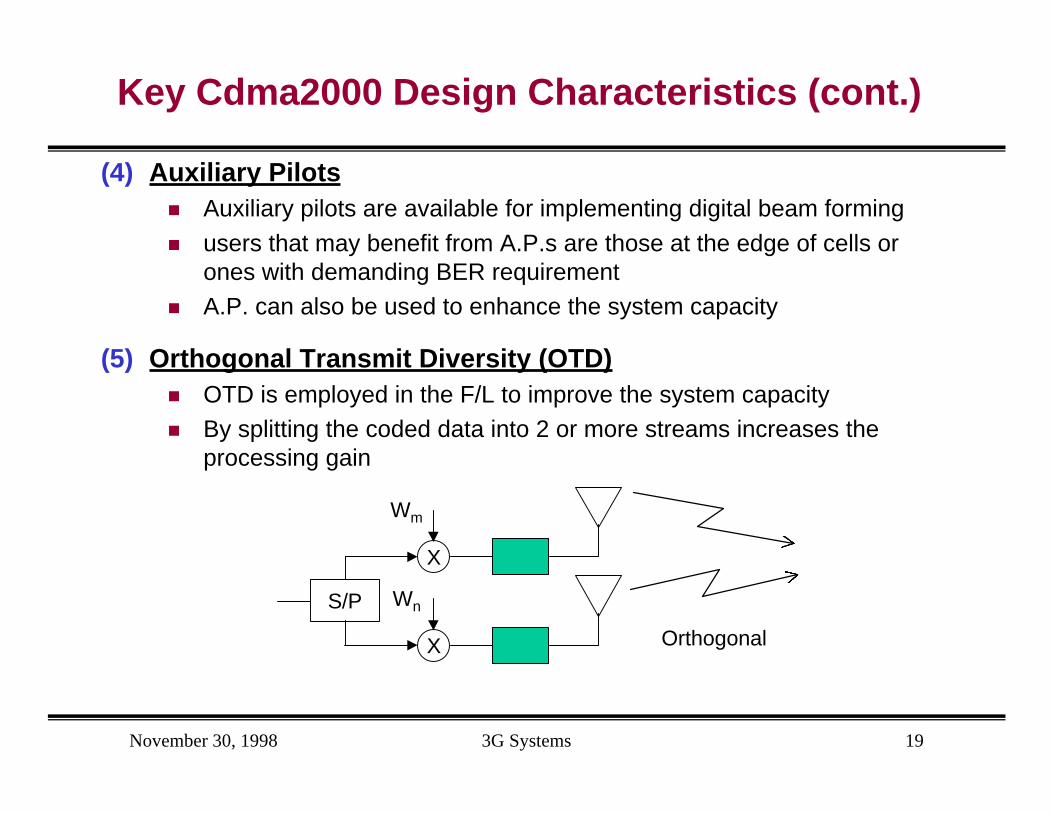
(5) Orthogonal Transmit Diversity (OTD)n OTD is employed in the F/L to improve the system capacityn By splitting the coded data into 2 or more streams increases the
processing gain
X
Wm
X
WnS/P
Orthogonal
November 30, 1998 3G Systems 20
Key Characteristics of 3G Networks
l So far, there is no agreement on the RTT. Most likely there will be severalRTT technologies (both 3G and 2G). There will a good market for multimodeterminals (Software Radio ?!)
l WRC-99 outlined the need for Global Radio Control Channel (RCC) to help ininternational roaming.
l The global RCC is expected to broadcast helpful information, including:
n IMT-2000 bands
n Clocks and timing references
n Identifications of public and private networks
n Availability of services …etc
l 3G networks will evolve from existing networks
l It is expected that the network aspects will converge more smoothly than theRTT aspects
November 30, 1998 3G Systems 21
ITU Model for IMT-2000 Interfaces
UIM MT RAN CNOtherCN's
UIM-MT MT-RAN RAN-CN CN-CN
UIM User Identity ModuleMT Mobile TerminalRANRadio Access NetworkCN Core Network
l The CN-CN interface is key for global roaming :
l ITU study group 11 (ITU-T-SG-11) is currently investigating a commonsignaling protocol for this interface.
November 30, 1998 3G Systems 22
Interworking Scenarios
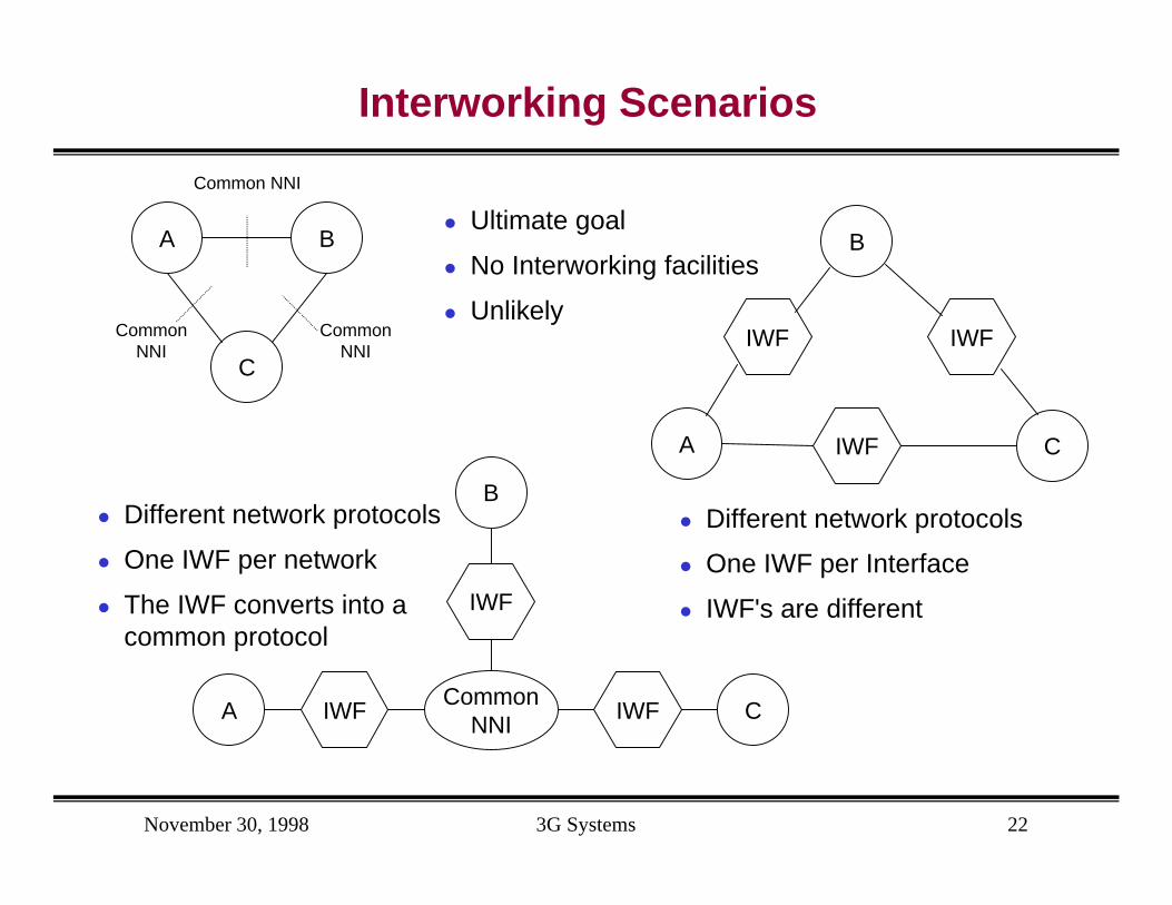
l Ultimate goal
l No Interworking facilities
l Unlikely
C
A B
Common NNI
CommonNNI
CommonNNI
CommonNNI
A
B
IWF IWF C
IWF
l Different network protocols
l One IWF per network
l The IWF converts into acommon protocol
A
B
IWF
IWF
C
IWF
l Different network protocols
l One IWF per Interface
l IWF's are different
November 30, 1998 3G Systems 23
Active Research Area
l Call admission algorithms. It involves jointoptimization of:
n Power assignment
n Han-off (Mandatory and forced)
n QoS Provisioning
l Optimizing the system capacity and admissionprocedures using auxiliary pilots
l Hybrid Space-Division-Multiple-Access (SDMA) andCDMA within the Cdma2000 frame work
l Classical ARQ-FEC trade-off in the context of powerassignment to multimedia wireless terminals