56
1 Third Runway Project – APM Depot Fire Engineering Design Presented by Ir Wilson Sau-kit TSANG 1

1
Third Runway Project – APM Depot Fire Engineering Design
Presented by Ir Wilson Sau-kit TSANG
1

2

Presentation Overview
1. Project Background and Depot Overview
2. Building Information and Challenge for Code
Compliant Design
3. Summary of Fire Safety Provisions
4. Non-code Compliant Items
5. Overview of Fire Engineering Approach
6. Fire Safety Management Plan
Project Background and Depot Overview1
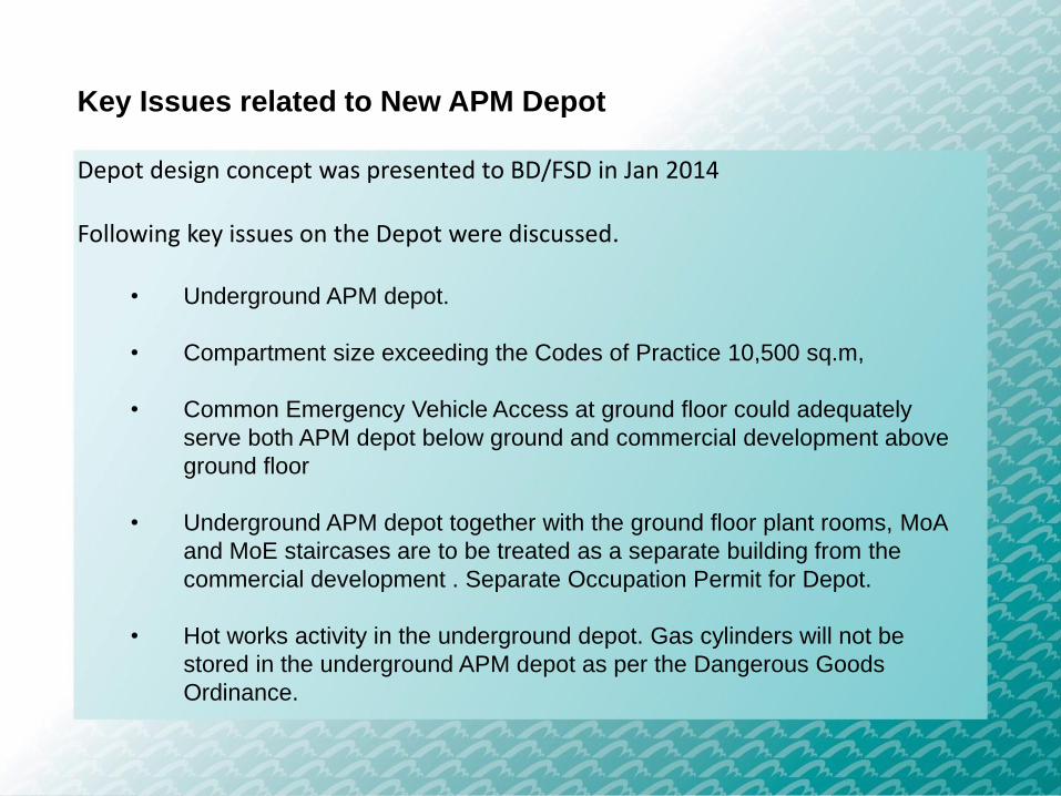
Key Issues related to New APM Depot
Depot design concept was presented to BD/FSD in Jan 2014
Following key issues on the Depot were discussed.
• Underground APM depot.
• Compartment size exceeding the Codes of Practice 10,500 sq.m,
• Common Emergency Vehicle Access at ground floor could adequately
serve both APM depot below ground and commercial development above
ground floor
• Underground APM depot together with the ground floor plant rooms, MoA
and MoE staircases are to be treated as a separate building from the
commercial development . Separate Occupation Permit for Depot.
• Hot works activity in the underground depot. Gas cylinders will not be
stored in the underground APM depot as per the Dangerous Goods
Ordinance.
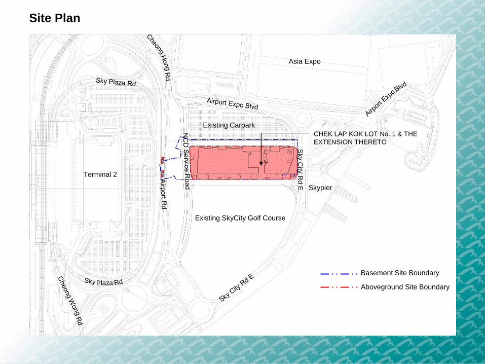
Site Plan
Sky C
ity R
d E
Plaza
CHEK LAP KOK LOT No. 1 & THE
EXTENSION THERETO
Existing SkyCity Golf Course
Terminal 2
Skypier
Asia Expo
Existing Carpark
Basement Site Boundary
Aboveground Site Boundary
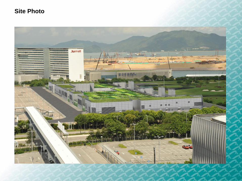
Site Photo

8
Building Information & Challenge for
Code Compliant Design
2
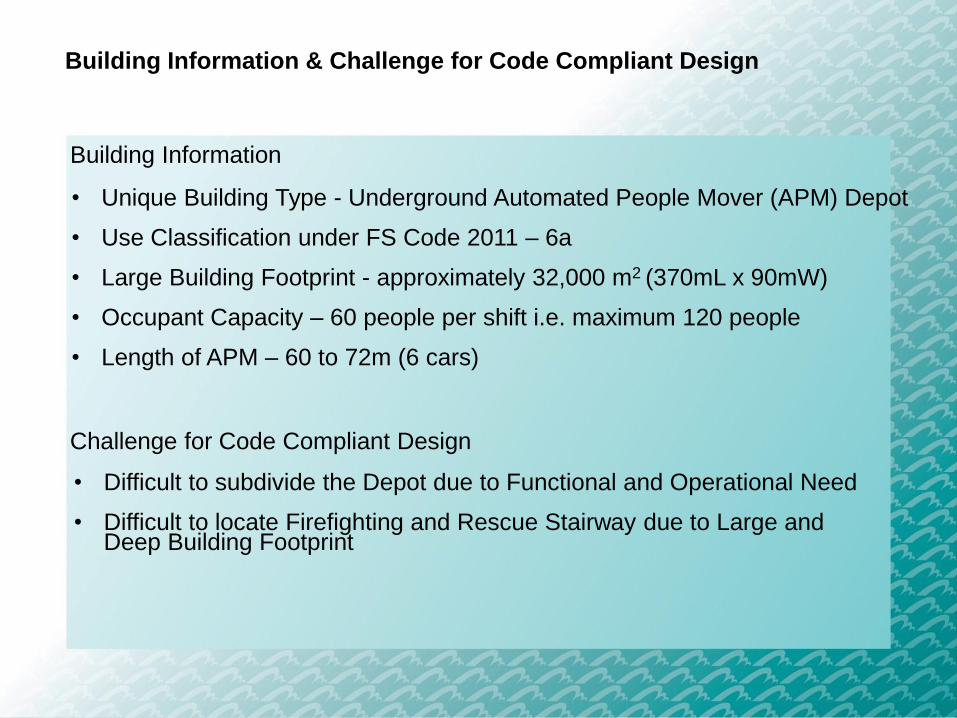
Building Information & Challenge for Code Compliant Design
• Unique Building Type - Underground Automated People Mover (APM) Depot
• Use Classification under FS Code 2011 – 6a
• Large Building Footprint - approximately 32,000 m2 (370mL x 90mW)
• Occupant Capacity – 60 people per shift i.e. maximum 120 people
• Length of APM – 60 to 72m (6 cars)
Building Information
Challenge for Code Compliant Design
• Difficult to subdivide the Depot due to Functional and Operational Need
• Difficult to locate Firefighting and Rescue Stairway due to Large and Deep Building Footprint

Level 1 Zoning Plan (Underground Level)
APM/BHS Tunnel between APM Interchange
Station and SkyPier/ITT Station
(A&A Plan and FER approved under separate
submission)
TRC APM Tunnel
(Under separate submission)Terminal 2 Expansion
(Under separate submission)
Support Area
and Plant Area
Support Area
and Plant AreaMaintenance and Stabling Area
(Third Runway Concourse Line)
T1 Line Turnback
Maintenance and Stabling Area
(Terminal 1 Line / SkyPier Line)
-4.610 FFL
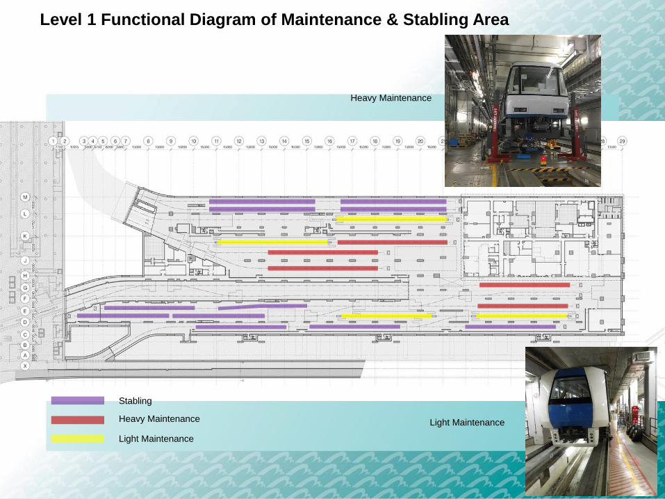
Level 1 Functional Diagram of Maintenance & Stabling Area
Stabling
Heavy Maintenance
Light Maintenance
Heavy Maintenance
Light Maintenance

Level 2 Plan (Mezzanine Level)
+1.415 FFL
Maintenance Platform
High Level Protected Corridor

Level 3 Plan (Ground Level) – FRS and MOE Staircase
+7.140 FFL
Firefighting and Rescue Stairway
Plant Room
Loading Bay
Soil Surcharge
MOE Staircase
Airp
ort
Ro
ad
Under
T2 Submission

Longitudinal Section – Future NCD above
Envisaged Area to be handed over to NCD
Support Area and Plant Area
Maintenance and Stabling Area
L3 +7.140 FFL
L2 +1.415 FFL
L1 -4.610 FFL
6025
5725

Summary of Fire Safety Provisions3
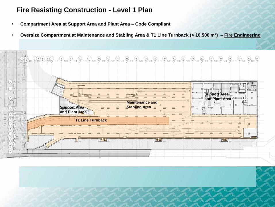
Fire Resisting Construction - Level 1 Plan
• Compartment Area at Support Area and Plant Area – Code Compliant
• Oversize Compartment at Maintenance and Stabling Area & T1 Line Turnback (> 10,500 m2) – Fire Engineering
Support Area
and Plant Area
Support Area
and Plant Area
Maintenance and
Stabling Area
T1 Line Turnback
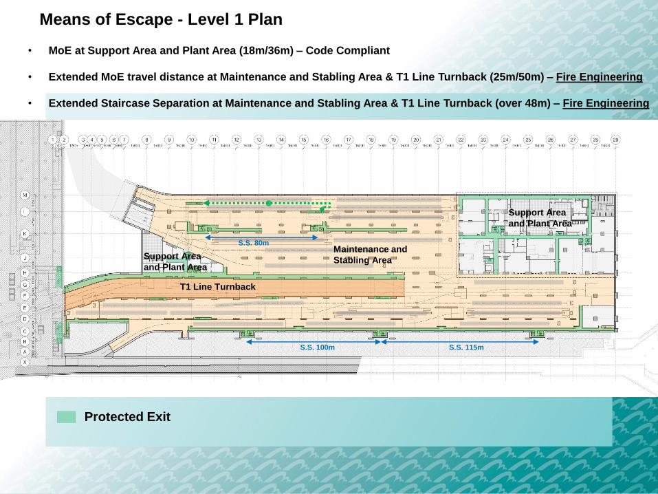
Means of Escape - Level 1 Plan
• MoE at Support Area and Plant Area (18m/36m) – Code Compliant
• Extended MoE travel distance at Maintenance and Stabling Area & T1 Line Turnback (25m/50m) – Fire Engineering
• Extended Staircase Separation at Maintenance and Stabling Area & T1 Line Turnback (over 48m) – Fire Engineering
Protected Exit
Support Area
and Plant Area
Support Area
and Plant Area
Maintenance and
Stabling Area
T1 Line Turnback
S.S. 80m
S.S. 100m S.S. 115m

Means of Access - Level 3 Plan
Fire Service Access Point
13.5m
13.5m
7.3m
• EVA – Code Compliant
Emergency Vehicular Access
Airp
ort
Ro
ad

Means of Access (Firefighting and Rescue Stairway) - Level 1 Plan
• MoA travel distance at Support Area and Plant Area – Code Compliant
• Extended MoA travel distance at Maintenance and Stabling Area & T1 Line Turnback – Fire Engineering
Firefighting and Rescue Stairway
Extended MoA Protected Corridor
Support Area
and Plant Area
Support Area
and Plant Area
Maintenance and
Stabling Area
T1 Line Turnback
Non-code Compliant Items4

Non-code Compliant Items
Maintenance and Stabling Area
(Terminal 1 Line / SkyPier Line)
Maintenance and Stabling Area
(Third Runway Concourse Line)
Maintenance and Stabling Area
T1 Line Turnback
Fire Engineering Approach to justify:
NC1: Oversize fire compartment
NC2: Extended MoE travel distance
NC3: Extended staircase separation
NC4: Extended MoA travel distance
T1 Line Turnback
Terminal 2 Expansion
Separate submission
Third Runway Concourse APM Tunnel
Separate submission
SkyPier APM/BHS Tunnel
Separate submission
Support Area and Plant Area
Follow FS Code 2011
Support Area and Plant Area
Follow FS Code 2011
Support
Area and
Plant Area
Support Area
and Plant Area

Deviation from Deemed-to-
Comply ProvisionsNon-code Compliant Designs
FS Code 2011 (Clause C3.1)
Every building should be
divided into fire compartments
by fire barriers without
exceeding the prescribed limit
of fire compartment area
(10,500m2).
Maintenance and Stabling Area:
~20,000m2
T1 Line Turnback:
~2,700m2 with no fire separation with
adjoining APM tunnel
Non-code Compliant Items
NC1: Oversize fire compartment
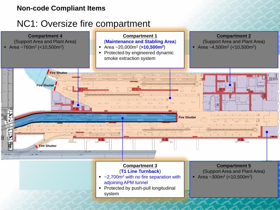
Compartment 1
(Maintenance and Stabling Area)
Area ~20,000m2 (>10,500m2)
Protected by engineered dynamic
smoke extraction system
Compartment 2
(Support Area and Plant Area)
Area ~4,500m2 (<10,500m2)
Compartment 5
(Support Area and Plant Area)
Area ~300m2 (<10,500m2)
Fire Shutter
Fire Shutter
Fire Shutter
Fire Shutter
Non-code Compliant Items
NC1: Oversize fire compartmentCompartment 4
(Support Area and Plant Area)
Area ~760m2 (<10,500m2)
Compartment 3
(T1 Line Turnback)
~2,700m2 with no fire separation with
adjoining APM tunnel
Protected by push-pull longitudinal
system

Deviation from Deemed-to-
Comply ProvisionsNon-code Compliant Designs
FS Code 2011 (Clause B11.2)
The dead end travel distance
is limited to 18m to a protected
exit or to a point from which
travel in different directions to
2 or more protected exits is
available.
FS Code 2011 (Clause B11.3)
Travel distance to the nearest
protected exit is limited to 36m
when two or more protected
exits are available.
Maintenance and Stabling Area:
≤50m to the nearest protected exit and
≤25m for dead end situation
T1 Line Turnback:
Exit points at both ends of T1 Line
Turnback (260m apart)
Non-code Compliant Items
NC2: Extended travel distance for means of escape

Key
Protected Corridor Protected Exit of
Maintenance and
Stabling Area
Locations of Protected Exits for Maintenance and Stabling Area and
T1 Line Turnback (Level 1)
Protected Staircase
Non-code Compliant Items
Exit Point of T1
Line Turnback
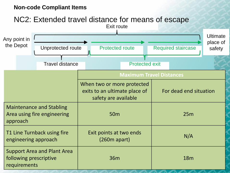
Exit route
Ultimate
place of
safety
Any point in
the Depot
Travel distance Protected exit
Maximum Travel Distances
When two or more protected exits to an ultimate place of
safety are availableFor dead end situation
Maintenance and Stabling Area using fire engineering approach
50m 25m
T1 Line Turnback using fire engineering approach
Exit points at two ends (260m apart)
N/A
Support Area and Plant Area following prescriptive requirements
36m 18m
Protected route Required staircaseUnprotected route
Non-code Compliant Items
NC2: Extended travel distance for means of escape

Level 1 Key Plan
Level 1 Enlarge View
MoE Travel Distance Illustration
8
E
15
47m
47m
Non-code Compliant Items
NC2: Extended travel distance for means
of escape

Deviation from Deemed-to-
Comply ProvisionsNon-code Compliant Designs
FS Code 2011 (Clause B11.3b)
The horizontal distance
measured on plan along the
centreline of the exit route
between a required staircase
or a discharge point and any
one of the other required
staircases or discharge points
should not exceed 48m.
Maximum separation between two
staircases will be >48m.
Non-code Compliant Items
NC3: Extended staircase separation

Deviation from Deemed-to-
Comply ProvisionsNon-code Compliant Designs
FS Code 2011 (Clause D15.6)
No part of the floor served by a
FRS should be more than 60m
from the door of the lobby to
the FRS measured along
actual passages.
Maintenance and Stabling Area:
≤60m from the door of the protected
corridor
T1 Line Turnback:
Firemen can access to the T1 Line
Turnback from either end of T1 Line
Turnback (260m apart)
Non-code Compliant Items
NC4: Extended travel distance for means of access for
firefighting and rescue
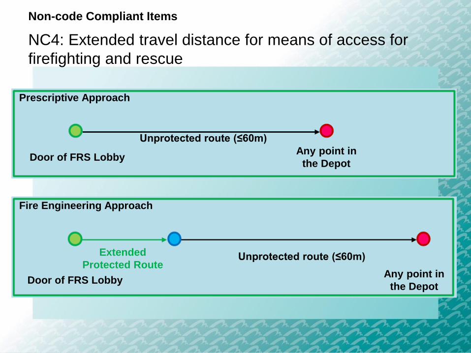
Any point in
the Depot
Unprotected route (≤60m)
Prescriptive Approach
Door of FRS Lobby
Fire Engineering Approach
Door of FRS Lobby
Unprotected route (≤60m)Extended
Protected RouteAny point in
the Depot
Non-code Compliant Items
NC4: Extended travel distance for means of access for
firefighting and rescue

Key
Fire Service Access Point FS Control Room
FS Control
Room
EVA
EVA
EVA
Non-code Compliant Items
NC4: Extended travel distance for means of access for
firefighting and rescue
Key
Protected Corridor Protected Exit of
Maintenance and
Stabling Area
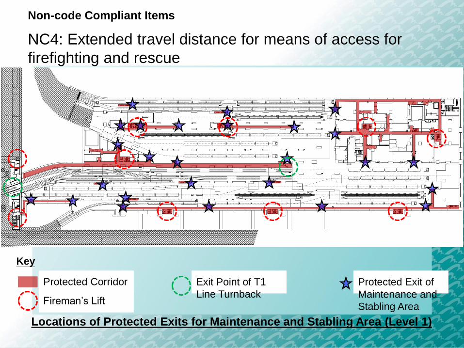
Locations of Protected Exits for Maintenance and Stabling Area (Level 1)
Fireman’s Lift
Non-code Compliant Items
NC4: Extended travel distance for means of access for
firefighting and rescue
Exit Point of T1
Line Turnback

Level 1 Key Plan
Level 1 Enlarge View
MoA Travel Distance Illustration
Fireman’s Lift
54m54m
15 21
D
Non-code Compliant Items
NC4: Extended travel distance for means of access for
firefighting and rescue
Overview of
Fire Engineering Approach
5
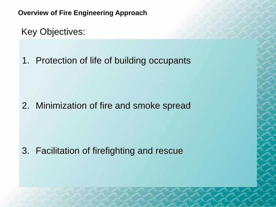
Overview of Fire Engineering Approach
Key Objectives:
1. Protection of life of building occupants
2. Minimization of fire and smoke spread
3. Facilitation of firefighting and rescue

Overview of Fire Engineering Approach
ASET/RSET Analysis
1. Available Safe Egress Time (ASET) by Computational
Fluid Dynamics (CFD) analysis using Fire Dynamics
Simulator (FDS)
2. Required Safe Egress Time (RSET) by evacuation
analysis using STEPS
3. ASET > RSET with safety factor of ≥1.5
Bottom level of smoke barriers = 5.76m AFFL
Smoke extraction rate = 119m3/s
Bottom level of smoke barriers = 4.25m AFFL
Smoke extraction rate = 77m3/s
905m2
850m2
990m2
1040m2
1415m2
1190m2
1965m2
1680m2 1600m2 1965m2 1845m2 1895m2 1430m2 1760m2
875m2
1480m2
Section A-A’
A
A’
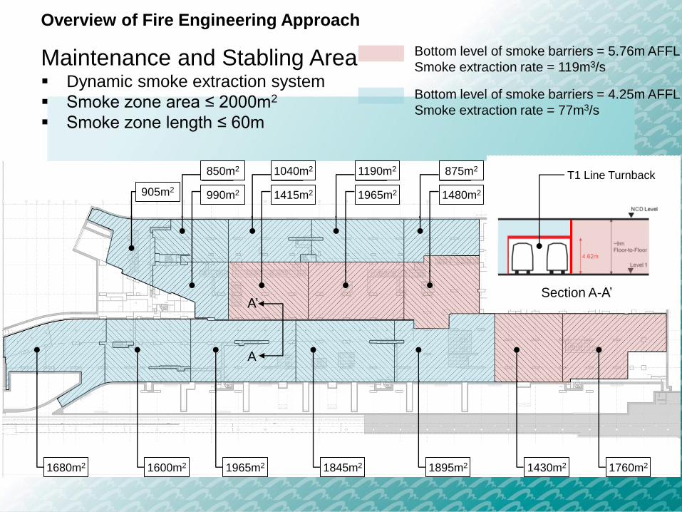
Overview of Fire Engineering Approach
Maintenance and Stabling Area Dynamic smoke extraction system
Smoke zone area ≤ 2000m2
Smoke zone length ≤ 60m
T1 Line Turnback

Smoke Extraction System (Maintenance / Stabling Area)
Mechanical – Smoke Extraction System
• Subdivided into (16) smoke zones
• Area ≤ 2000m2 and Length ≤60m
• Boundary fire scenario confined across TWO smoke zones only
Smoke Clear Height Smoke Extraction Rate (w/ 10% safety)
Light Maintenance/Stabling Area 4450 AFFL 77 m3/s
Heavy Maintenance Area 5960 AFFL 119 m3/s

Bottom level of smoke barriers = 5.76m AFFL
Smoke extraction rate = 119m3/s
Bottom level of smoke barriers = 4.25m AFFL
Smoke extraction rate = 77m3/s
Scenario 1
• 10MW APM fire
• Three-side connections
with other smoke zones
Scenario 2
• 10MW APM fire
• Three sides enclosed by
walls
Scenario 3
• 10MW APM fire
• Three sides enclosed by
walls
Scenario 4
• 10MW APM fire
• Three sides enclosed by
walls
Scenario 5
• 10MW APM fire
• Boundary fire scenario
Overview of Fire Engineering Approach
CFD Simulation Scenarios

Smoke Extraction System (Maintenance / Stabling Area)
Mechanical – Smoke Extraction System
• Dual purpose ductwork (SED / EAD), four dedicated smoke extraction plants, each plant comprises with N duty + 1 standby smoke extraction fan
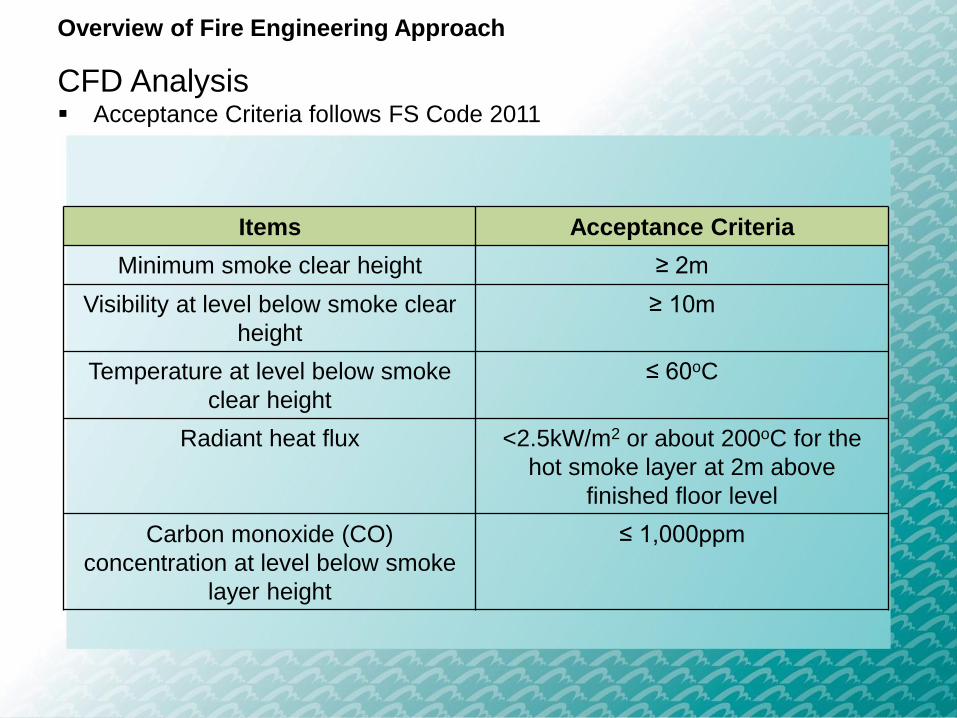
Items Acceptance Criteria
Minimum smoke clear height ≥ 2m
Visibility at level below smoke clear
height
≥ 10m
Temperature at level below smoke
clear height
≤ 60oC
Radiant heat flux <2.5kW/m2 or about 200oC for the
hot smoke layer at 2m above
finished floor level
Carbon monoxide (CO)
concentration at level below smoke
layer height
≤ 1,000ppm
Overview of Fire Engineering Approach
CFD Analysis Acceptance Criteria follows FS Code 2011
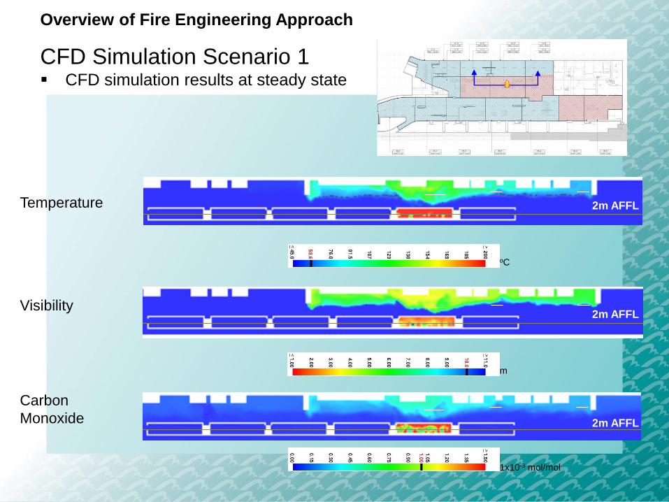
Temperature
Visibility
Carbon
Monoxide
oC
m
1x10⁻³ mol/mol
2m AFFL
2m AFFL
2m AFFL
Overview of Fire Engineering Approach
CFD Simulation Scenario 1 CFD simulation results at steady state
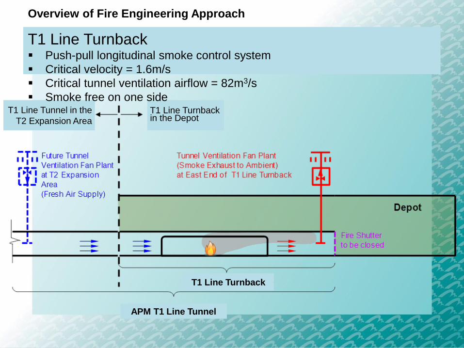
T1 Line Turnback in the Depot
T1 Line Tunnel in the
T2 Expansion Area
T1 Line Turnback
APM T1 Line Tunnel
Overview of Fire Engineering Approach
T1 Line Turnback Push-pull longitudinal smoke control system
Critical velocity = 1.6m/s
Critical tunnel ventilation airflow = 82m3/s
Smoke free on one side
Overview of Fire Engineering Approach
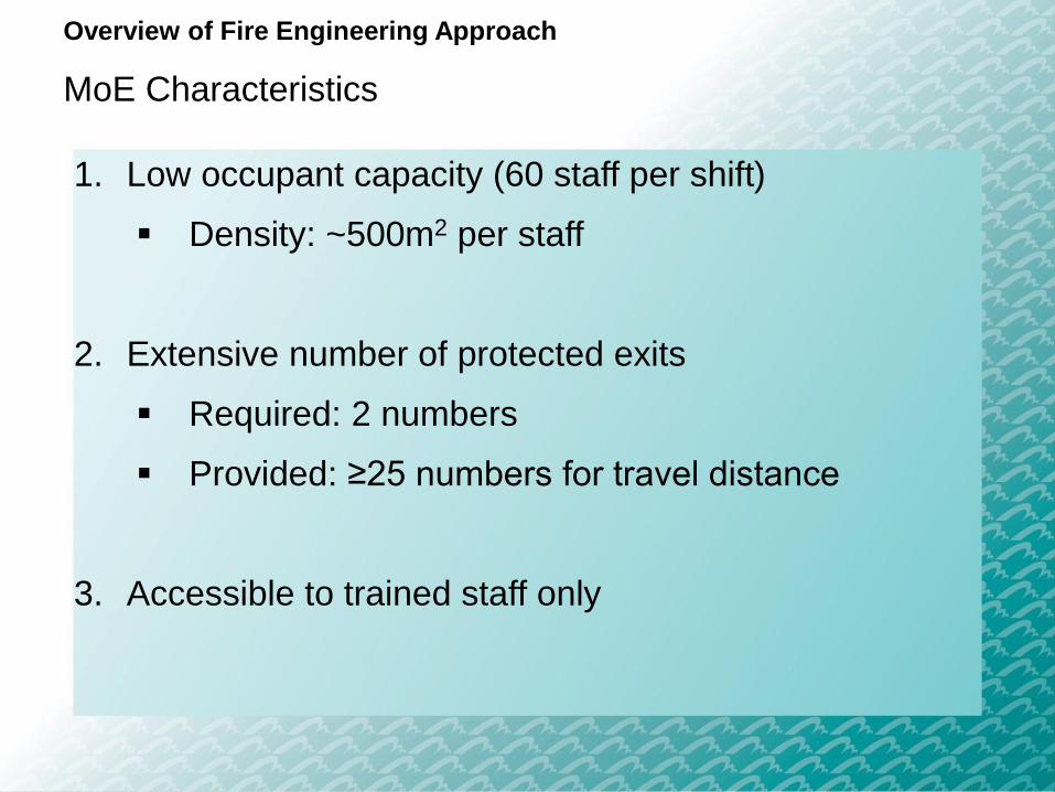
MoE Characteristics
1. Low occupant capacity (60 staff per shift)
Density: ~500m2 per staff
2. Extensive number of protected exits
Required: 2 numbers
Provided: ≥25 numbers for travel distance
3. Accessible to trained staff only
Overview of Fire Engineering Approach
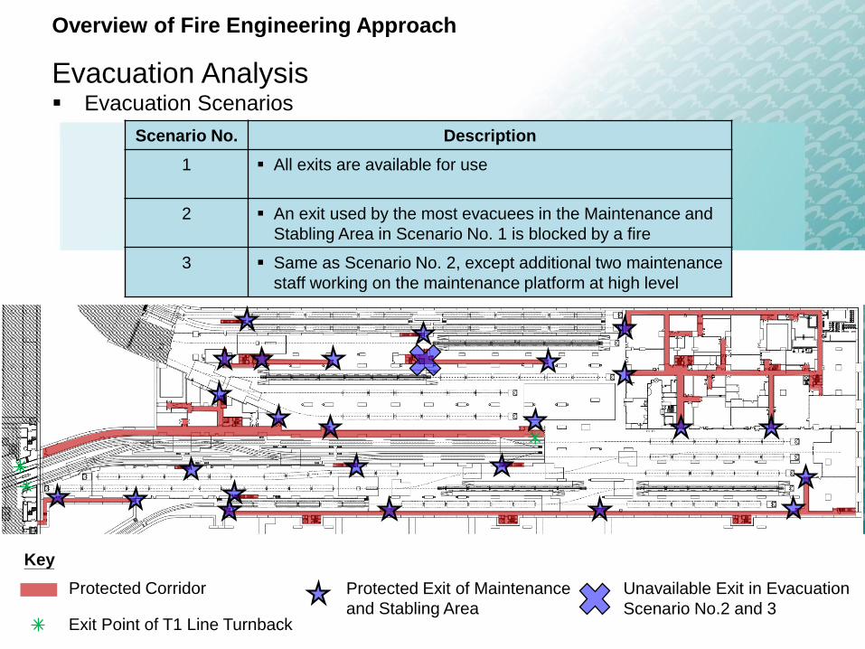
Evacuation Analysis Evacuation Scenarios
Scenario No. Description
1 All exits are available for use
2 An exit used by the most evacuees in the Maintenance and
Stabling Area in Scenario No. 1 is blocked by a fire
3 Same as Scenario No. 2, except additional two maintenance
staff working on the maintenance platform at high level
Protected Corridor
Exit Point of T1 Line Turnback
Protected Exit of Maintenance
and Stabling Area
Unavailable Exit in Evacuation
Scenario No.2 and 3
Key
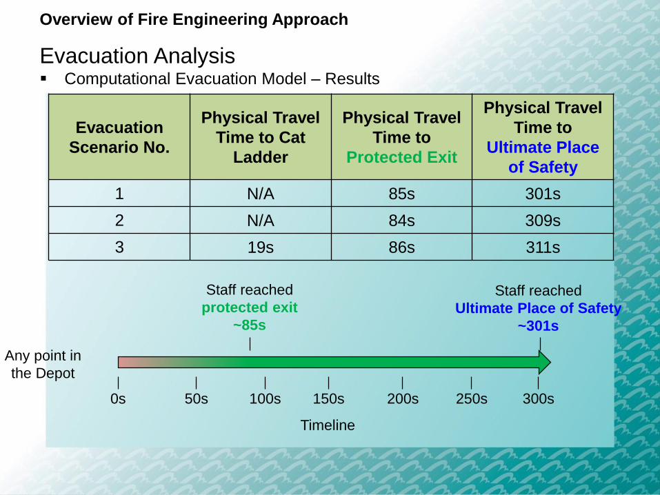
Evacuation
Scenario No.
Physical Travel
Time to Cat
Ladder
Physical Travel
Time to
Protected Exit
Physical Travel
Time to
Ultimate Place
of Safety
1 N/A 85s 301s
2 N/A 84s 309s
3 19s 86s 311s
Overview of Fire Engineering Approach
Evacuation Analysis Computational Evacuation Model – Results
Any point in
the Depot
Staff reached
Ultimate Place of Safety
~301s
Timeline
0s 300s150s 200s 250s50s 100s
Staff reached
protected exit
~85s

Parameter Time
Time to raise a fire alarm (1) 172s
Pre-movement time (2) 90s
Physical travel time (3) 86s
RSET, (1) + (2) + (3) 348s
ASET 3,600s
Safety Factor (ASET / RSET) 10.3
Overview of Fire Engineering Approach
ASET/RSET Analysis
Timeline
ASET
RSET3,600s
348s
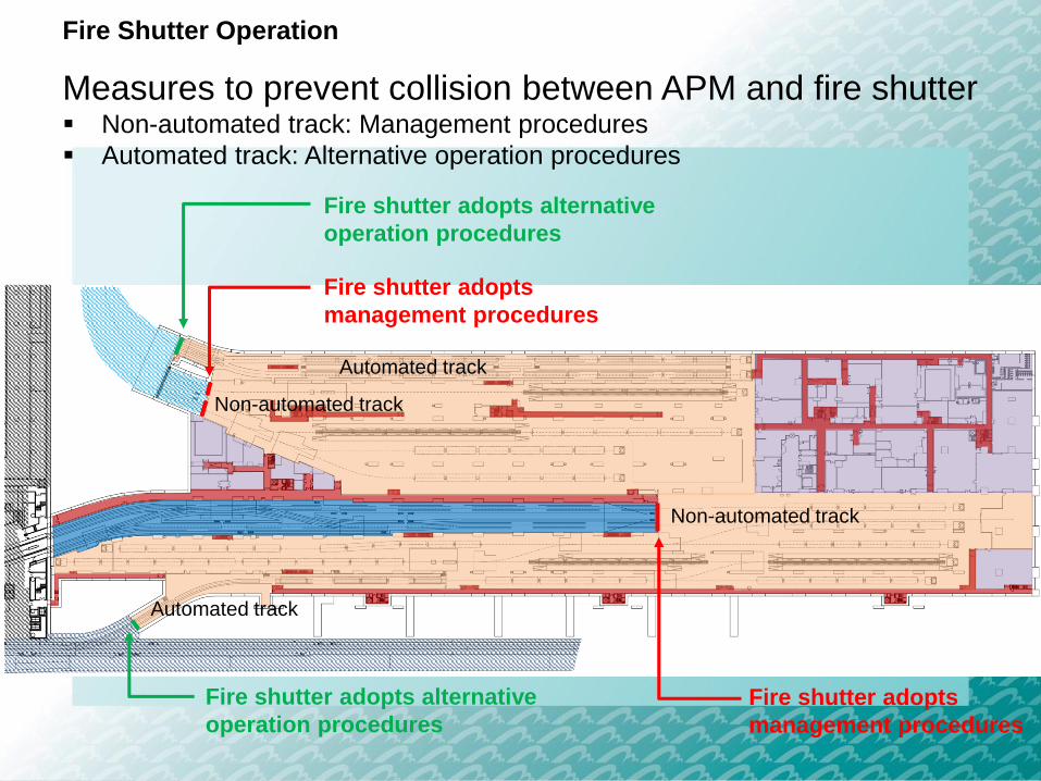
Fire Shutter Operation
Measures to prevent collision between APM and fire shutter Non-automated track: Management procedures
Automated track: Alternative operation procedures
Fire shutter adopts alternative
operation procedures
Fire shutter adopts
management procedures
Fire shutter adopts
management procedures
Fire shutter adopts alternative
operation procedures
Automated track
Non-automated track
Non-automated track
Automated track

Fire Shutter Operation
Non-automated track: Management procedures
Before APM passing through fire shutter line
• Ground technician to present at the fire shutter lines
• Ground technician, operator in APM Central Control Room and APM vehicle operator to inform each other the next action to be carried out
During APM passing through fire shutter line
• Ground technician to push and hold the “stop” button of fire shutter continuously
After APM passing through fire shutter line
• Ground technician to check the APM passed the fire shutter line
• Ground technician to release the “stop” button of fire shutter

Fire Shutter Operation
Automated track: Alternative operation procedures
APM Operation and Fire Shutter Operation
Location of APM
Fire signal to close fire shutter
Closing signal to fire shutter
Outside “Approach
Zone”
APM to stop before fire
shutter
Fire shutter to descend within
15 to 60s
Within “Approach
Zone”
APM to continue movement until
leaving fire shutter (45s)
Fire shutter to be descended
within 15 to 60s
“Approach Zone”: This zone is defined as a distance from the fire shutter in which a 6-car
APM, travelling at the allowed speed, would be able to stop before the line of fire shutter,
assuming worst-case braking profile.

Fire Safety Management
Plan
6
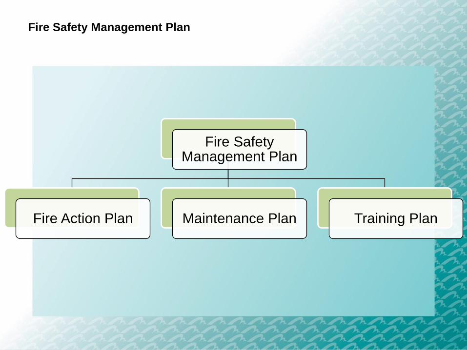
Fire Safety Management Plan
Fire Safety Management Plan
Fire Action Plan Maintenance Plan Training Plan
Fire Safety Management Plan
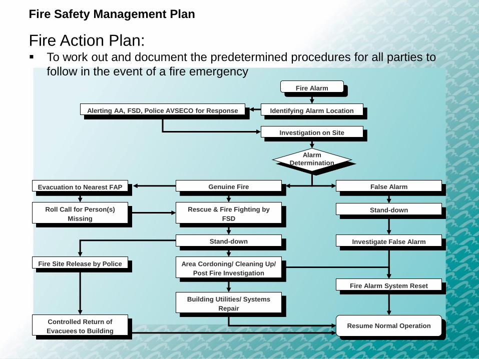
Fire Action Plan: To work out and document the predetermined procedures for all parties to
follow in the event of a fire emergency
Fire Alarm
Identifying Alarm LocationAlerting AA, FSD, Police AVSECO for Response
Investigation on Site
Genuine Fire False Alarm
Rescue & Fire Fighting by
FSD
Evacuation to Nearest FAP
Alarm
Determination
Roll Call for Person(s)
Missing
Stand-down
Investigate False AlarmStand-down
Fire Site Release by Police Area Cordoning/ Cleaning Up/
Post Fire Investigation
Fire Alarm System Reset
Building Utilities/ Systems
Repair
Resume Normal OperationControlled Return of
Evacuees to Building

Fire Safety Management Plan
Maintenance Plan To document the periodic maintenance requirements so that fire safety
provisions are kept in good working order
Maintenance Plan
Follow statutory maintenance requirements
Proper maintenance records
Regular housekeeping
Work Permit System and Permit-to-Work System
Fire Safety Management Plan
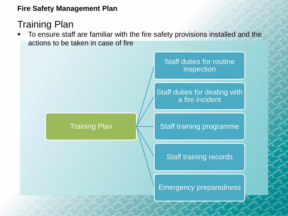
Training Plan To ensure staff are familiar with the fire safety provisions installed and the
actions to be taken in case of fire
Training Plan
Staff duties for routine inspection
Staff duties for dealing with a fire incident
Staff training programme
Staff training records
Emergency preparedness

Thank You


