38 SILICON CHIP M odern electronics allows products – consumer, indus- trial and scientific – to be produced with more features in smaller packages at less cost than ever before. Not too long ago, the controller for an appliance such as a washing ma- chine or microwave oven would have been a mechanical timer, or perhaps discrete components (switches, tran- sistors and 4000 series logic, etc). However, all these things take pre- cious space and are costly to produce. Often they’re difficult to update or reuse for different product models or revisions. Today, these problems are neatly and cheaply solved with microcon- trollers – single chip computers com- plete with IO pins, RAM, pProgram storage (ROM) and sometimes other useful features like ADCs, UARTS and PWM drivers. One simply arranges for relevant inputs (switches and sensors) and out- puts (motor and solenoid drivers, LEDs and displays) to be connected to the microcontroller and then write some software to manage the lot. The space saving and cost effective- ness of these small wonders are rea- son enough to use them. But when you consider the flexibility they pro- vide to adapt the control system to changes in the device or consumer demanded functionality they are in- dispensable. Changes are simple: you change the software (which can often be done in- circuit) and the same hardware will perform the new task. There are very few fields left in electronic engineering where microcontrollers have not made their mark. It is becoming more and more important to understand how micro- controllers work and how they are applied in designs – and how to de- velop and debug their software. Fortunately, there are many sources on the Internet open to the engineer and hobbyist alike that provide free tools, examples and designs. Micro- This article presents two simple, low One will count up or down and the user-defined ways from a preset val the modules is the software in t By Peter Crowcroft and controller manufacturers have lots of details in their datasheets and appli- cation notes, so that is a good place to start. The counter circuits The use of an ATMEL AVR micro- controller allows the circuit to be greatly simplified. A larger range of useful features can be provided than could be achieved with conventional logic circuits. If we wanted to make a simple coun- ter with conventional logic, we would need some components to condition the input and output signals, a coun- ter for each digit (say a 74LS192 BCD Decade Counter), and then we would need to drive a 7-segment LED dis- play using a BCD to 7-segment driver (74LS47). Straight away we have eight ICs (two per digit). Then we’d need some “glue logic” to hang everything together. And we’d get a counter that can only count up. To fit this into a rea- sonable space we’d have to use a dou- ble-sided board with plated-through holes because of the large number of connections required between ICs. We might even need to go to surface mount components to reduce the size. It begins to get very expensive and complex, not to mention tedious (if not impossible) for the hobbyist to assemble. (Yes, some hobbyists work with sur- face mount components but they are very much the exception to the rule!) TECHNICAL SPECIFICATIONS – Up/Down Counter Supply voltage 9-15V DC (<40mA @ 12V) Operating modes Count Up (default), Count Down, Count Disable, Overflow, Reset Count range 0000 to 9999 or 0000 to 0001 (0000, 9999, 9998, ... 0001) Count rate Maximum count rate of 30 to 35 counts per second Inputs Reset, Count (negative edge triggered), Count down Output NPN Transistor,100mA @ 30V Display 14mm red LED, 7-segment common anode Physical size 51mm x 63mm Connection 10-pin SIL header pins, 0.1”
Transcript
38 SILICON CHIP
Modern electronics allowsproducts – consumer, indus-trial and scientific – to be
produced with more features insmaller packages at less cost than everbefore.
Not too long ago, the controller foran appliance such as a washing ma-chine or microwave oven would havebeen a mechanical timer, or perhapsdiscrete components (switches, tran-sistors and 4000 series logic, etc).
However, all these things take pre-cious space and are costly to produce.Often they’re difficult to update orreuse for different product models orrevisions.
Today, these problems are neatlyand cheaply solved with microcon-trollers – single chip computers com-plete with IO pins, RAM, pProgramstorage (ROM) and sometimes otheruseful features like ADCs, UARTS andPWM drivers.
One simply arranges for relevantinputs (switches and sensors) and out-puts (motor and solenoid drivers, LEDs
and displays) to be connected to themicrocontroller and then write somesoftware to manage the lot.
The space saving and cost effective-ness of these small wonders are rea-son enough to use them. But whenyou consider the flexibility they pro-vide to adapt the control system tochanges in the device or consumerdemanded functionality they are in-dispensable.
Changes are simple: you change thesoftware (which can often be done in-circuit) and the same hardware willperform the new task.
There are very few fields left inelectronic engineering wheremicrocontrollers have not made theirmark. It is becoming more and moreimportant to understand how micro-controllers work and how they areapplied in designs – and how to de-velop and debug their software.
Fortunately, there are many sourceson the Internet open to the engineerand hobbyist alike that provide freetools, examples and designs. Micro-
This article presents two simple, lowOne will count up or down and the
user-defined ways from a preset valthe modules is the software in t
By Peter Crowcroft and
controller manufacturers have lots ofdetails in their datasheets and appli-cation notes, so that is a good place tostart.
The counter circuitsThe use of an ATMEL AVR micro-
controller allows the circuit to begreatly simplified. A larger range ofuseful features can be provided thancould be achieved with conventionallogic circuits.
If we wanted to make a simple coun-ter with conventional logic, we wouldneed some components to conditionthe input and output signals, a coun-ter for each digit (say a 74LS192 BCDDecade Counter), and then we wouldneed to drive a 7-segment LED dis-play using a BCD to 7-segment driver(74LS47). Straight away we have eightICs (two per digit). Then we’d needsome “glue logic” to hang everythingtogether.
And we’d get a counter that canonly count up. To fit this into a rea-sonable space we’d have to use a dou-ble-sided board with plated-throughholes because of the large number ofconnections required between ICs.
We might even need to go to surfacemount components to reduce the size.It begins to get very expensive andcomplex, not to mention tedious (ifnot impossible) for the hobbyist toassemble.
(Yes, some hobbyists work with sur-face mount components but they arevery much the exception to the rule!)
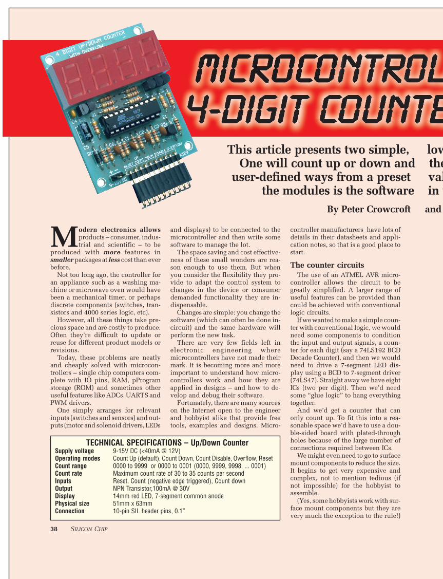
TECHNICAL SPECIFICATIONS – Up/Down CounterSupply voltage 9-15V DC (<40mA @ 12V)Operating modes Count Up (default), Count Down, Count Disable, Overflow, ResetCount range 0000 to 9999 or 0000 to 0001 (0000, 9999, 9998, ... 0001)Count rate Maximum count rate of 30 to 35 counts per secondInputs Reset, Count (negative edge triggered), Count downOutput NPN Transistor,100mA @ 30VDisplay 14mm red LED, 7-segment common anodePhysical size 51mm x 63mmConnection 10-pin SIL header pins, 0.1”
MAY 2001 39
With the microcontroller solutionpresented here, this complexity is re-duced to one IC only and a handful ofdiscrete components to condition theinput and output signals, all on a small(cheap!) single-sided PC board. All
the hardware complexity has vanishedinto the software where finding andfixing errors is easy.
As we shall see, we also get the abil-ity to change and add more useful fea-tures and modes of operation easily.
The Up/Down Counter has an over-flow output, allowing multiple unitsto be “daisy-chained” together forgreater counter range. The unit willcount between 0000 and 9999, pro-ducing the overflow pulse when the
le, low-cost, four-digit counter modules.and the other will count down in severalset value. The main difference betweenare in the microcontroller. roft and Frank Crivelli.
40 SILICON CHIP
count rolls over to 0000.The Presettable Down Counter al-
lows the user to program a startingcount and select one of four differentoperating modes which determinewhat happens when the count reaches0000.
Circuit descriptionThe modules are almost identical;
in fact the display driver, the powersupply and the output are identical.The differences are confined to theinputs and their “meaning” to the mi-crocontroller. Let’s start by looking atthe identical parts of the modules.
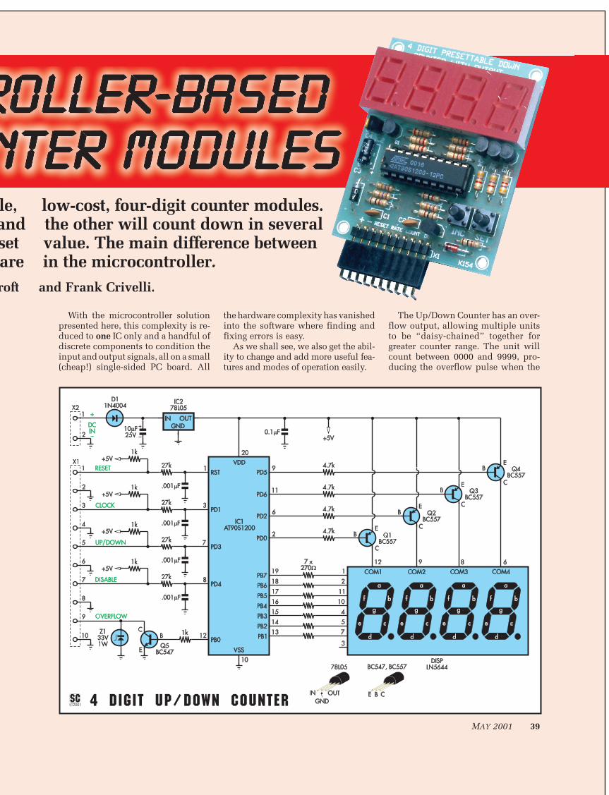
The counter modules are designedaround an AT90S1200 AVR microcon-troller from ATMEL (http://www.atmel.com). A detailed product data-sheet is available from this website.
This particular device was chosenbecause it has an internal R/C oscilla-tor, eliminating the need for an exter-nal crystal. This simplifies the circuitand further reduces component costs.
The display unit is a 4-digit, com-mon anode, multiplexed, 7-segmentLED display. This means that the LEDsin a single digit share a common an-ode (positive) connection. The cath-odes (negative) of the segments (a, b, …g & dp) are connected across the fourdigits, forming a matrix.
Multiplexing results in fewer con-nections and less board space beingdevoted to the display and reducesthe number of microcontroller out-puts required to drive the display. Onenegative is that the drive signals be-
come more complex but this is rela-tively simple to achieve in the micro-controller’s program.
Bits 1 to 7 of the microcontroller’sPort B are connected via 270Ω currentlimiting resistors (R1-R7) to the sharedsegment pins. Four of the Port D bitsare then connected to drive the fourcommon anodes via Q1-Q4, the PNPtransistors. Resistors R8-R11 (4.7kΩ)protect the transistors from excessivebase current which otherwise coulddestroy them.
To display the current count, themicrocontroller cycles through eachof the four digits one at a time, provid-ing current to the anode of the digit byturning on the appropriate transistor
(driving the base low).It then arranges for outputs con-
nected to the segments it wishes tolight to be driven low so that currentcan flow from the transistor, throughthe LEDs in the display and to groundvia the microcontroller port. The seg-ments it wishes to remain unlit aredriven high.
After approximately 1ms, the dis-play is extinguished and another 1msdelay occurs, then the next digit is lit.This then continues for the remainingdigits and the cycle starts again.
Therefore it takes about 8ms to fullydisplay the current count, which ismuch too fast for the human eye todiscern, so to us it looks like a con-stant display.
The software programmed into themicrocontroller uses a timer that trig-gers an interrupt about every 1ms toachieve this. When the interrupt oc-curs the next display is set up or thecurrent display is extinguished. Thisallows it to be monitoring the inputswithout constantly worrying abouthandling the display, simplifying thedesign of the software.
Transistor Q5, an NPN device, pro-vides an active low open collectoroutput for the overflow signal in theup/down counter version and the out-put signal in the presettable downcounter version. The remaining bit(Bit 0) of Port B drives this transistorvia R18, a 1kΩ resistor.
Q5 is protected by Zener diode Z1which will break down and conduct ifthe voltage across Q5 exceeds 33V, orit will conduct if a negative voltage is
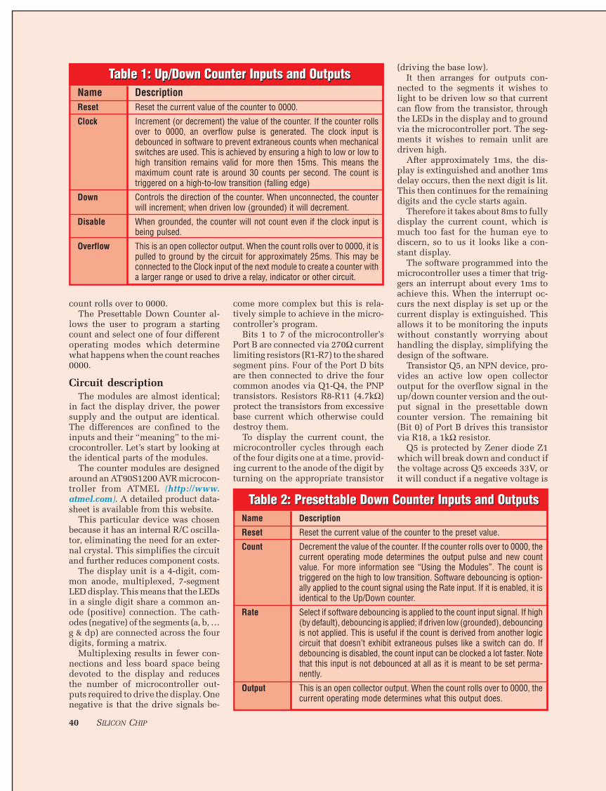
Table 2: Presettable Down Counter Inputs and OutputsName Description
Reset Reset the current value of the counter to the preset value.
Count Decrement the value of the counter. If the counter rolls over to 0000, thecurrent operating mode determines the output pulse and new countvalue. For more information see “Using the Modules”. The count istriggered on the high to low transition. Software debouncing is option-ally applied to the count signal using the Rate input. If it is enabled, it isidentical to the Up/Down counter.
Rate Select if software debouncing is applied to the count input signal. If high(by default), debouncing is applied; if driven low (grounded), debouncingis not applied. This is useful if the count is derived from another logiccircuit that doesn’t exhibit extraneous pulses like a switch can do. Ifdebouncing is disabled, the count input can be clocked a lot faster. Notethat this input is not debounced at all as it is meant to be set perma-nently.
Output This is an open collector output. When the count rolls over to 0000, thecurrent operating mode determines what this output does.
Table 2: Presettable Down Counter Inputs and Outputs
Table 1: Up/Down Counter Inputs and OutputsName DescriptionReset Reset the current value of the counter to 0000.
Clock Increment (or decrement) the value of the counter. If the counter rollsover to 0000, an overflow pulse is generated. The clock input isdebounced in software to prevent extraneous counts when mechanicalswitches are used. This is achieved by ensuring a high to low or low tohigh transition remains valid for more then 15ms. This means themaximum count rate is around 30 counts per second. The count istriggered on a high-to-low transition (falling edge)
Down Controls the direction of the counter. When unconnected, the counterwill increment; when driven low (grounded) it will decrement.
Disable When grounded, the counter will not count even if the clock input isbeing pulsed.
Overflow This is an open collector output. When the count rolls over to 0000, it ispulled to ground by the circuit for approximately 25ms. This may beconnected to the Clock input of the next module to create a counter witha larger range or used to drive a relay, indicator or other circuit.
Table 1: Up/Down Counter Inputs and Outputs
MAY 2001 41
applied to the collector. This is neededwhen driving inductive loads such asrelays, as the back EMF generated bythe collapsing magnetic field in thecoil when the current is turned off caneasily exceed the rating of the transis-tor and destroy it.
Power for the circuit is provided byan external 9-15V DC power supplyand is regulated by IC2, C4 and C5,resulting in a 5V supply.
IC2 looks like another transistor butis a 78L05 low-current voltage regula-tor in a TO-92 case. This regulatorneeds about 2.2V of headroom (ie,voltage in minus voltage out) to en-sure regulation.
Diode D1 provides reverse bias pro-tection in case the power supply isconnected the wrong way around. Asthere is about 0.6V or so drop acrossthis diode, you must ensure that thevoltage supplied to the circuit doesn’tdrop below about 8V (5V + 2.2V +0.6V~~ 8V)
Now let’s look at the input circuitsfor the different modules.
Up/Down counterThe Up/Down counter has four in-
puts and one output. These are de-tailed in Table 1.
The four inputs are all pulled highby the 1kΩ resistors and have a lowpass filter formed by a 27kΩ resistorand .001µF capacitor to filter out highfrequency noise from the line to re-duce the chance of false triggers. Thisfilter’s time constant is approximately20µs and any pulses shorter then thiswon’t make it to the microcontroller.A 20µs time constant equates to afrequency of 50kHz. The inputs arealso debounced in software with thelevel in the input needing to be con-stant for 15ms before it is recognisedas a valid input.
Presettable Down counterThe Presettable Down counter is a
little more complex. It has two push-button switches added to its inputs.These are used to program the presetvalue and operating mode. This mod-ule has three inputs and one output,as detailed in Table 2.
Like the other module, the inputs arepulled high by 1KΩ resistors. The Countand Reset inputs have the same lowpass filtering applied with the 27KΩresistors and .001µF capacitors.
The SET switch (SW1) is connecteddirectly to Port D, Bit 4 with a 1kΩpull-up resistor. There is no need forfiltering on this input as the micro-controller will debounce it in soft-ware.
The INC (SW2) switch is interest-
TECHNICAL SPECIFICATIONS – Presettable Down CounterSupply voltage 12VDC @ 50mAOperating modes Count Stop, Output Hold Over-Count, Output Hold
Auto-Reset, One-Shot Output Over-Count, One-Shot OutputCount range 0000 to 9999 (10,000 max)Count speed Low (selectable)
High 30 cps (15mS high, 15mS low) 30,000 cps (measured)Inputs Reset, Count, RateOutput NPN Transistor, 100mA @ 30VDisplay 14mm red LED, 7-segment common anodePhysical size 51mm x 63mmConnection 10 pin SIL header pins, 0.1”
42 SILICON CHIP
ing as it is shared with the Countinput. This is an example of makingefficient use of the available inputs.This can be done because in set-upmode, no counting in done. This alsomeans that the INC button can be usedto decrement the counter when it isrunning.
SoftwareThe software listing for the micro-
controller is not supplied, however
this description is provided for thosewho are curious or want to have a goat creating their own.
The first thing the code does is setup all the inputs and outputs andinitialises all the internal states. Itthen sets the count to the default value(0000 or the preset depending on themodule) and starts the internal timer.
The timer is set to trigger an inter-rupt every 200µs (observant readersmay notice I said 1ms earlier – I lied
Parts List - Up-down 4-Digit Up-Down Counter
4-Digit Presettable Down Counter
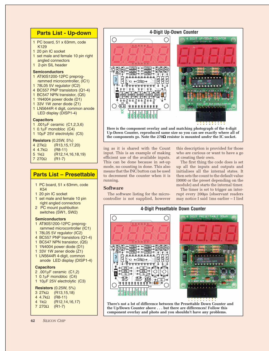
1 PC board, 51 x 63mm, codeK129
1 20 pin IC socket1 set male and female 10 pin right
There’s not a lot of difference between the Presettable Down Counter andthe Up/Down Counter above . . . but there are differences! Follow thiscomponent overlay and photo and you shouldn’t have any problems.
Here is the component overlay and and matching photograph of the 4-digitUp-Down Counter, reproduced same size so you can see exactly where all ofthe components go. Note the 270ΩΩΩΩΩ resistor is mounted under the IC socket.
Parts List – Presettable
MAY 2001 43
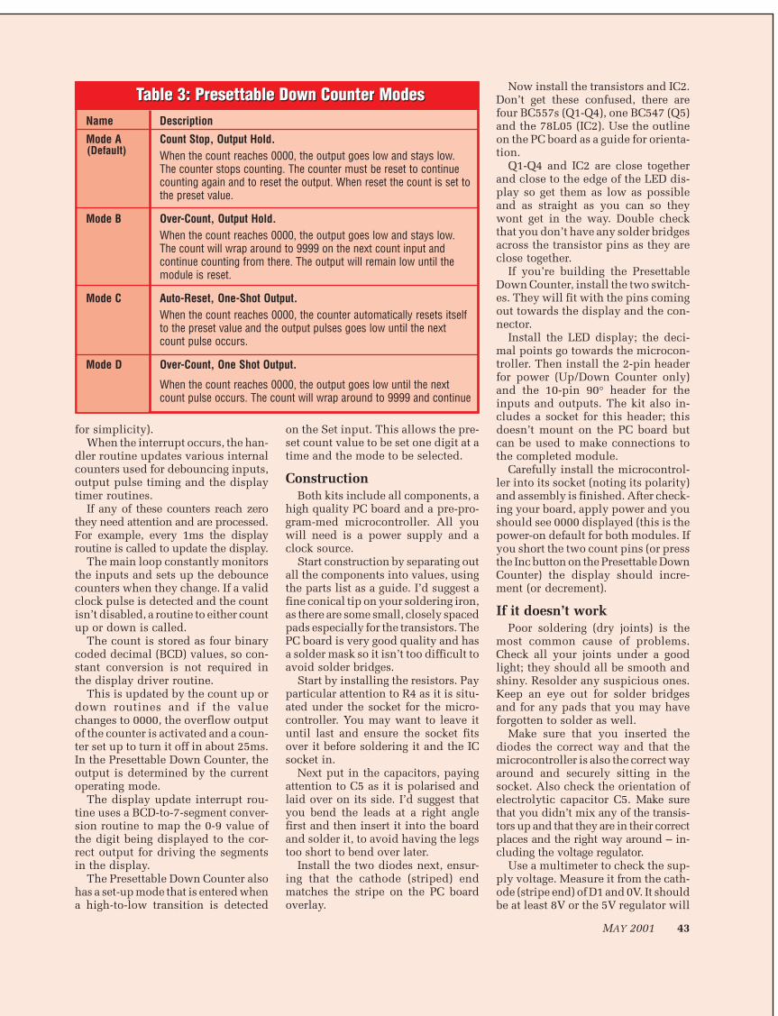
Table 3: Presettable Down Counter ModesName Description
Mode A Count Stop, Output Hold.When the count reaches 0000, the output goes low and stays low.The counter stops counting. The counter must be reset to continuecounting again and to reset the output. When reset the count is set tothe preset value.
Mode B Over-Count, Output Hold.When the count reaches 0000, the output goes low and stays low.The count will wrap around to 9999 on the next count input andcontinue counting from there. The output will remain low until themodule is reset.
Mode C Auto-Reset, One-Shot Output.When the count reaches 0000, the counter automatically resets itselfto the preset value and the output pulses goes low until the nextcount pulse occurs.
Mode D Over-Count, One Shot Output.
When the count reaches 0000, the output goes low until the nextcount pulse occurs. The count will wrap around to 9999 and continue
Table 3: Presettable Down Counter Modes
(Default)
for simplicity).When the interrupt occurs, the han-
dler routine updates various internalcounters used for debouncing inputs,output pulse timing and the displaytimer routines.
If any of these counters reach zerothey need attention and are processed.For example, every 1ms the displayroutine is called to update the display.
The main loop constantly monitorsthe inputs and sets up the debouncecounters when they change. If a validclock pulse is detected and the countisn’t disabled, a routine to either countup or down is called.
The count is stored as four binarycoded decimal (BCD) values, so con-stant conversion is not required inthe display driver routine.
This is updated by the count up ordown routines and if the valuechanges to 0000, the overflow outputof the counter is activated and a coun-ter set up to turn it off in about 25ms.In the Presettable Down Counter, theoutput is determined by the currentoperating mode.
The display update interrupt rou-tine uses a BCD-to-7-segment conver-sion routine to map the 0-9 value ofthe digit being displayed to the cor-rect output for driving the segmentsin the display.
The Presettable Down Counter alsohas a set-up mode that is entered whena high-to-low transition is detected
on the Set input. This allows the pre-set count value to be set one digit at atime and the mode to be selected.
ConstructionBoth kits include all components, a
high quality PC board and a pre-pro-gram-med microcontroller. All youwill need is a power supply and aclock source.
Start construction by separating outall the components into values, usingthe parts list as a guide. I’d suggest afine conical tip on your soldering iron,as there are some small, closely spacedpads especially for the transistors. ThePC board is very good quality and hasa solder mask so it isn’t too difficult toavoid solder bridges.
Start by installing the resistors. Payparticular attention to R4 as it is situ-ated under the socket for the micro-controller. You may want to leave ituntil last and ensure the socket fitsover it before soldering it and the ICsocket in.
Next put in the capacitors, payingattention to C5 as it is polarised andlaid over on its side. I’d suggest thatyou bend the leads at a right anglefirst and then insert it into the boardand solder it, to avoid having the legstoo short to bend over later.
Install the two diodes next, ensur-ing that the cathode (striped) endmatches the stripe on the PC boardoverlay.
Now install the transistors and IC2.Don’t get these confused, there arefour BC557s (Q1-Q4), one BC547 (Q5)and the 78L05 (IC2). Use the outlineon the PC board as a guide for orienta-tion.
Q1-Q4 and IC2 are close togetherand close to the edge of the LED dis-play so get them as low as possibleand as straight as you can so theywont get in the way. Double checkthat you don’t have any solder bridgesacross the transistor pins as they areclose together.
If you’re building the PresettableDown Counter, install the two switch-es. They will fit with the pins comingout towards the display and the con-nector.
Install the LED display; the deci-mal points go towards the microcon-troller. Then install the 2-pin headerfor power (Up/Down Counter only)and the 10-pin 90° header for theinputs and outputs. The kit also in-cludes a socket for this header; thisdoesn’t mount on the PC board butcan be used to make connections tothe completed module.
Carefully install the microcontrol-ler into its socket (noting its polarity)and assembly is finished. After check-ing your board, apply power and youshould see 0000 displayed (this is thepower-on default for both modules. Ifyou short the two count pins (or pressthe Inc button on the Presettable DownCounter) the display should incre-ment (or decrement).
If it doesn’t workPoor soldering (dry joints) is the
most common cause of problems.Check all your joints under a goodlight; they should all be smooth andshiny. Resolder any suspicious ones.Keep an eye out for solder bridgesand for any pads that you may haveforgotten to solder as well.
Make sure that you inserted thediodes the correct way and that themicrocontroller is also the correct wayaround and securely sitting in thesocket. Also check the orientation ofelectrolytic capacitor C5. Make surethat you didn’t mix any of the transis-tors up and that they are in their correctplaces and the right way around – in-cluding the voltage regulator.
Use a multimeter to check the sup-ply voltage. Measure it from the cath-ode (stripe end) of D1 and 0V. It shouldbe at least 8V or the 5V regulator will
44 SILICON CHIP
have difficulties and not operate cor-rectly. The voltage from the output ofthe regulator should be within a fewtens of millivolts of 5V.
If it’s much lower, then you prob-ably have the regulator in back-to-front or something (such as a solderbridge or misplaced component) iscausing too much current to be drawnfrom the regulator, shutting it down.If it’s much higher, check for a solderbridge across the regulator pads (orthe regulator itself might be shot).
Using the modulesThe counter module has three or
four inputs and one output that areaccessed via a 10-way header. Theinput lines are all active low, whichmeans that grounding them performstheir function. More correctly, eachof the inputs is normally pulled highby the module circuitry and must bepulled low to become active.
Each of the lines has a correspond-ing ground pin beside it, simplifyingthe connection to a switch. The inputlines may be connected to simple ‘make’contacts, switches, relays or even opencollector outputs from other circuits.
The module requires a 9 to 15V DCpower supply and consumes between20mA and 40mA, depending on thenumber being displayed. A smallplugpack will easily supply enoughpower for several modules. Alterna-tively, the module could be battery pow-ered.
The Up/Down Counter is fairlystraightforward. Just connect a switchto the count input and set the directionon the Down input and you’re ready togo. However, the Presettable DownCounter, is a little more complex.
Connect the count input and out-put as needed, and then apply powerto the unit. By default, it will display0000. It will overflow to 9999 andcontinue counting down with clockinputs until it reaches 0000 again.This is Mode A and it is the defaultmode. A description of each of themodes is given in Table 3.
The two pushbuttons marked, SET
and INC are used to configure boththe preset value and the operatingmode. The preset value is enteredone digit at a time starting at the thou-sands and then the Mode is selected.
To enter the programming mode,press the SET button. The displaywill show the preset value for thethousands digit and the rest of thedisplay shows a minus (-) sign. Usethe INC button to select the requiredvalue then press the SET button toadvance to the next digit.
Continue setting each of the presetdigit values unit the last one is set.The display will now show the cur-rent operating mode with the lettersA, b, C or d. Use the INC button toselect the desired mode and press theSET button to accept it. This will alsoexit programming mode and the coun-ter is ready for use.
Software flexibilityTo illustrate the power of using a
microcontroller versus discrete logiccircuit the following “user requested”modifications have been made to theUp/Down counter at no cost to theuser since the change was very easyto do in software (note these changesare not included in the kit software –they are mentioned only to illustratethe ease of change).
1. Count by five instead of by one.2. Show digits “upside down” so
the PC board could be placed in a pre-designed box upside down.
3. Only display digits on a “key-press” so that the kit could be moreefficiently battery powered.
These were done by simply chang-ing the software. Try doing that withdiscrete logic circuits!!!
Further informationThe following may be good starting
points to find more information:• ATMEL (makers of the micro-
controller used in this project) have awebsite at www.atmel.com There youwill find data-sheets for all their mi-cro-controllers with detailed informa-tion about using and programmingthem.
• DIY Electronics (the kit manu-facturer for this project) have a websiteat http://kitsrus.com
They also have an AVR Program-mer kit (Kit 122) and BASCOM BasicCompiler which are useful for peoplewishing to experiment with AVR mi-cro-controllers.
PROGRAMMING THEDOWN COUNTER
Two pushbutton switches, marked“SET” and “INC”, are used to presetthe starting count and select the op-erating mode. Presetting the countvalue is done one digit at a time,starting with the thousands digit.
Press the SET button to enterprogramming mode. The displayshows the current preset value of thethousands digit and the rest of thedisplay shows minus (–) signs. Usethe INC button to set the value re-quired. Press the SET button whendone.
The current preset hundreds digitis shown. Use the INC button to setthe value required. Press the SETbutton when done.
Repeat the above steps for thetens and units digits.
After setting the units digit thedisplay shows the current operatingmode. The mode is indicated by theletters “A, b, C or d”. Use the INCbutton to set the operating mode thenpress SET to exit programming mode.The display will blank momentarily toindicate that programming mode hasended.
The counter is now ready for use.As mentioned before the RESET
input resets the counter to its presetvalue. It does not change the operat-ing mode. If the counter loses powerit will restart in Mode A with a presetvalue of “0000” (count = 10,000).
Questions or comment about theKit can be directed to Peter Crowcroft,[email protected], while technicalquestions may be directed to the kit’sdesigner, Frank Crivelli, [email protected]
Kit availabilityCopyright of the kit designs, the PC
board patterns and the software (re-siding in the microcontroller) is re-tained by DIY Electronics (HK) Ltd.
A kit of parts for either of these kitsmay be obtained from Jaycar Electron-ics stores, Jaycar mail order or via theironline store at www.jaycar.com. au.
Both kits sell for $39.95.The 4-Digit Up/Down Counter is
Cat No KD-6084, while the 4-DigitPresettable Down Counter is Cat NoKD-6058. SC
Table 4: Resistor Colour CodesNo. Value 4-Band Code (5%)
3 27kΩ red violet orange gold 4 4.7kΩ yellow violet red gold 4 1kΩ brown black red gold 7 270Ω red violet brown gold