This copy is a reprint which includes current pages from Changes 1 and 2. DEPARTMENT OF THE ARMY TECHNICAL MANUAL *TM 11-1520-209-ESC EQUIPMENT SERVICEABILITY CRITERIA FOR ELECTRONIC EQUIPMENT CONFIGURATIONS IN ARMY MODEL CH-47 SERIES HELICOPTERS Headquarters, Department of the Army, Washington, D.C., 24 August 1973 Paragraph Section I. INSTRUCTIONS .......................................................................................................... 1 through 5 II. COMMUNICATION SYSTEM EVALUATION PROCEDURE ......................................... 6 and 7 III. NAVIGATION SYSTEM EVALUATION PROCEDURE ...................................................8 and9 IV. STABILIZATION SYSTEM EVALUATION PROCEDURE ............................................ 10 and 11 V. AUXILIARY SYSTEM EVALUATION PROCEDURE .................................................... 12 and 13 Section I. INSTRUCTIONS 1. Purpose. This manual furnishes the user with a procedure for evaluating the readiness condition of the equipment to perform satisfactorily its primary mission for 90 days with normal maintenance support. NOTE Application of this procedure, however, does not eliminate or reduce the requirement for prescribed maintenance service on the equipment and does not authorize replacement of components. 2. Definitions. a. Equipment Category GREEN. Equipment free of conditions that would reduce its capability for reliable performance of its primary mission for a period of 90 days. b. Equipment Category AMBER. Operationally ready equipment with limitations which may curtail a reliable performance of its primary mission for a period of 90 days. c. Equipment Category RED. Equipment unable to perform its primary mission immediately or possessing an unacceptable reliability level for 90 days sustained performance of its primary mission. d. Color Rating. Rating of equipment accessories, components, etc., in accordance with a, b, and c above. e. Multiple-aspect equipment. Equipment of one logistic manager which contains subsystems, end items, or components of another logistics manager. 3. General Instructions. a. This technical manual will be filed in the equipment, -log binder. If classified. this technical manual will be filed in accord; ice with the provisions of AR 380-5. b. This evaluation will be actually performed on the item being rated by the operator/crew. ______________ * This manual supersedes TM 11-1520-209-ESC. 3 April 1969, including all changes. 1 Change 1
Transcript
This copy is a reprint which includes currentpages from Changes 1 and 2.
DEPARTMENT OF THE ARMY TECHNICAL MANUAL *TM 11-1520-209-ESC
EQUIPMENT SERVICEABILITY CRITERIAFOR
ELECTRONIC EQUIPMENT CONFIGURATIONS IN ARMY MODELCH-47 SERIES HELICOPTERS
Headquarters, Department of the Army, Washington, D.C., 24 August 1973
ParagraphSection I. INSTRUCTIONS ..........................................................................................................1 through 5
II. COMMUNICATION SYSTEM EVALUATION PROCEDURE ......................................... 6 and 7III. NAVIGATION SYSTEM EVALUATION PROCEDURE ...................................................8 and9IV. STABILIZATION SYSTEM EVALUATION PROCEDURE ............................................ 10 and 11V. AUXILIARY SYSTEM EVALUATION PROCEDURE.................................................... 12 and 13
Section I. INSTRUCTIONS
1. Purpose. This manual furnishes the user with a procedure forevaluating the readiness condition of the equipment to perform satisfactorilyits primary mission for 90 days with normal maintenance support.
NOTE
Application of this procedure, however, does not eliminate orreduce the requirement for prescribed maintenance serviceon the equipment and does not authorize replacement ofcomponents.
2. Definitions. a. Equipment Category GREEN. Equipment free ofconditions that would reduce its capability for reliable performance of itsprimary mission for a period of 90 days.
b. Equipment Category AMBER. Operationally ready equipment withlimitations which may curtail a reliable performance of its primary mission fora period of 90 days.
c. Equipment Category RED. Equipment unable to perform itsprimary mission immediately or possessing an unacceptable reliability levelfor 90 dayssustained performance of its primary mission.
d. Color Rating. Rating of equipment accessories, components, etc.,in accordance with a, b, and c above.
e. Multiple-aspect equipment. Equipment of one logistic managerwhich contains subsystems, end items, or components of another logisticsmanager.
3. General Instructions. a. This technical manual will be filed inthe equipment, -log binder. If classified. this technical manual will be filed inaccord; ice with the provisions of AR 380-5.
b. This evaluation will be actually performed on the item being ratedby the operator/crew.
______________* This manual supersedes TM 11-1520-209-ESC. 3 April 1969, including all changes.
1 Change 1
TM 11-1520-209-ESC
c. Authorized subsystems and components of multiple-aspectequipment requiring evaluation but which are not available at the organizationshall be given the lowest color rating authorized for that item.
d. Equipment covered in this manual which requires serviceabilitychecks but which is not authorized to the evaluating organization shall not berated.
e. This equipment is rated on the basis of capability for immediateoperation and amount of wear life remaining on limited life components. Therating is not meaningful unless each check is made with the utmost care andaccuracy.
f. Record the evaluation results on DA Form 2404, EquipmentInspection and Maintenance Worksheet, using a separate sheet for eachmultiple-aspect item of equipment, subsystem or component, including thoseevaluated by separately published ESC technical manuals. The blocks willbe completed in accordance with TM 38-750.
g. If an URGENT modification work order has not been applied to anyauthorized equipment, the equipment and the system will be rated "RED".
h. Subsystems and components will be separately color rated.i. A color rating will be assigned for the overall system.
4. Special Instructions. The electronic configuration in the aircraft mayvary, depending on the year of manufacture, production run, geographicalarea of operation, etc. The equipment that may be installed in the variousconfigurations is listed below. Refer to the master log of the aircraft to betested to determine which equipment should be installed in the particularaircraft. For’ the purpose of ESC evaluations, equipment listed in the masterlog shall be considered as authorized for the particular aircraft. Equipmentlisted below, but not listed in the master log of the aircraft, shall beconsidered as unauthorized.
a. Communication System (Section II).
(1) Control Intercommunications Set C-1611( *)/AIC (item 2).(2) Radio Set AN/ARC-44, fm communications (item 3).(3) Radio Set AN/ARC-54 or AN/ARC-131, fm communication
(witbou’tTSEC/KY-28 or MD-736/A installed) (item 4).(4) Radio Set AN/ARC-54 or AN/ARC-131 end communications
Security Set TSEC/KY-28 (item 5).(5) Radio Set AN/ARC-54 or AN/ARC-131 and Discrete Signal
Discriminator MD-736/A (item 6).(6) Radio Set AN/ARC-55( *), ubƒ communications (item 7).(7) Radio Set AN/ARC-SIX or AN/ARC-51BX, ubƒ
communications (item 8).(8) Radio Set AN/ARC-73( *), vbƒ communications (item 9).(9) Radio Set ARC Type 12 (Transmitter, Radio T-366A/ARC,
emergency h/ communications) (item 10).(10) Radio Set AN/ARC-134, vbƒ communications (item II).(11) Radio Set AN/ARC-102. b/ communications (item 12).(12) Transponder Set AN/APX-72 or Transponder Set AN/APX44
IFF transponder (item 13).(13) (Item 14 deleted.)
b Navigation System (Section III).(1) Radio Set AN/ARC-44 and Antenna Group AN/ARA-31, ƒm
boming (item 16).(2) Radio Sat AN/ARC-54 or AN/ARC-131 and Antenna Group
AN/ARA-56. or AS-1922 ƒm boming (item 17).(3) Radio Receiver R-1041A/ARN, marker beacon (item 18).(4) Direction Finder Set AN/ARN-59(V) radio compass (item 19).(5) Direction Finder Set AN/ARN-83, radio compass (item 20).(6) Receiving Set. Radio AN/ARN-30D or AN/ARN-30E vor
(item 21).
2
TM 11-1520-209-ESC
(7) Receiving Set, Radio AN/ARN-82( *), vor (item 22).(8) Aircraft Magnetic Compass. TypeJ-2 (item 23).(9) Gyromagnetic Compass A N/ASN-43 (item 24).
c. Stabilization System (Section IV).(1) Stability Augmentation System (SAS) (items 26 and 27).(2) Speed Trim Facility (item 28).
d. Auxiliary System (Section V). Proximity Waning System (item 30,)
5. Reporting of Errors. The reporting of errors, omissions, andrecommendations for improving this publication by the individual user isencouraged. Reports should be submitted on DA Form 2028(Recommended Changes to Publications) and forwarded directly toCommander, U.S. Army Electronics Command, ATTN: AMSEL-MA-Q, FortMonmouth, NJ., 07703.
Section II. COMMUNICATION SYSTEM EVALUATION PROCEDURE
6. Evaluation Requirements. a. Aircraft Placement. Have theaircraft placed in a location that is clear of obstructions such as largebuildings, hangars. powerlines, and other aircraft.
b. Power Application.(1) Auxiliary power. For those tests not requiring engine
operation, items 2 thru 12 use external power or the aircraft auxiliary powerunit.
(2) Aircraft power. Tests given in item 13 require the use ofaircraft engines and aircraft flight controls. For that item. use qualifiedpersonnel to operate the aircraft. Refer to TM 55-1520-209-10 for CH-47Ahelicopters. Refer to TM 55-1520-227-10 for CH-47B and CH-47Chelicopters.
c. Controls. Before beginning the tests, set the communicationequipment controls to their normal OFF positions. Set the aircraft ac and dc
circuit breakers so that power is available to operate the equipment. Performthe tests from each position in turn to insure a complete check of thecommunication facilities.
CAUTION
Communication equipments require a 3-minute warmup priorto operation except the uhf radio set which requires a 5-minute warmup period.
7. Procedure. a. All information will be determined by actualinspection and operation of the equipment. Evaluate each item listed andrecord the proper color rating on DA Form 2404 as described in Section I. Alloperator/crew preventive maintenance checks and services shall beperformed prior to evaluation.
Item 1. MWORATINGS
PROCEDUREGREEN AMBER RED
Determine if all pertinent URGENT All pertinent URGENT One or more URGENTMWO have been applied. MWO have been applied. MWO have not been applied.
3 Change 1 TM 11-1520-209-ESC
4 TM 11-1520-209-ESC
Item 2. Control, Intercommunications Set C-1611(*)/AIC, Interphone OperationRATINGS
PROCEDUREGREEN AMBER RED
Note: The following serviceability Adequate sidetone heard Audio heard in pilot’s Audio not heard in pilot’stest applies only to the interphone in headsets; undistorted and copilot’s headset; or copilot’s headsets.function of the C-161 I(*)/AIC. Otherfunctions of the C-161 1(*)/AIC, withcommunication and navigation equipment interconnected, are tested inother items.Set pilot’s,. copilot’s andcrewmember’s C-161 I(*)/AIC forinterphone operation. Operate pilot’smicrophone switch for interphoneand speak into microphone. Repeatfrom copilot’s and crewmember’spositions.
audio heard at a comfortable levelin the pilot’s, copilot’s andcrewmember’s headsets.
other positionsinopoperative.
Item 3. Radio Set AN/ARC-44, Fm CommunicationsRATINGS
PROCEDUREGREEN AMBER RED
Note: Establish two-waycommunication with a tactical fmstation located not less than I milefrom the aircraft. Caution: Do not setthe REM-LOCAL switch to REM; thereceiver-transmitter unit will notoperate properly. Set the pilot’s andcopilot’s C-161 1(*)/AIC for fmcommunication. Turn the SB-327/ARC-44 on and set to a frequency of a local tactical fm station.Set the FM-HOME switch on the SA-474/AR to FM. Establish two-way
Strength and readability of signalsare adequate to maintain reliablecommunication from both positions(pilot’s and copilot’s). Squelchdisabling operative sidetone heard
Reliable communicationspossible from one position only. No sideoneheard; squelch disablinginoperative.
No reliable two-way communication possiblefrom either position
.
5Item 3. Radio Set AN/ARC-44. Fm Communications (Continued)
RATINGSPROCEDURE
GREEN AMBER REDcommunication from pilot’s andcopilot’s position. in turn Aftercommunication check. tune SB-327ARC-44 to an unused channel andcheck squelch disabling
Item 4 Radio Set AN ARC-54 or AN ARC- 131 Fm Communications (Without TSEC KY-28 or MD-736,A Installed)RATINGS
PROCEDUREGREEN AMBER RED
Note: Establish two waycommunication with a tactical fmstation located not less than I milefrom the aircraft Set the pilot’s.copilot’s and troop commander’s C-1611(*) AIC for fm communicationOn the FM COMM control panel.select the frequency of a distanttactical fm station and set the modecontrol to PTT or T/R Establish two-way communication from the pilot’s.copilot’s. and troop commander’spositions. In turn Aftercommunication check. set the FMCOMM control panel to an unusedchannel and check squelch disabling.
Strength and readability of signalsare adequate to maintain reliablecommunications from each position(pilot’s. copilot’s and troopcommander’s) Squelch disablingoperative; sidetone heard.
Reliable communicationspossible from oneposition only No sidetoneheard Squelch disablinginoperative.
No reliable two-way communication possiblefrom either position.
TM 11-1520-209-ESC
Item 5 Radio Set AN/ARC-54 or AN/ARC- 131 and Communications Security Set TSEC/KY-28RATINGS
PROCEDUREGREEN AMBER RED
Note: A tactical fm station equippedwith a compatible security encoderand located not less than 1 mile fromthe aircraft is required. Set the FMCOMM control panel to the frequencyof a suitably equipped tactical fmstation Set the C-8157/AR(’ tooperate in the plain language modeSet the pilot’s. copilot’s. and troopcommander’s C- 161 I()/AIC for fmcommunication. Establish two-waycommunication in the plain languagemode from the pilot’s. copilot’s.And troop commander’s position. Inturn. Set the C-8157/ARC to operatein the secure mode. Establish two-way communication in the securemode.
Strength and readability of signalsare adequate to maintain reliablecommunications in plain languageand secure modes from eachposition (pilot’s. copilot’s and troopcommander’s).
Secure communicationsnot possible.
No reliable two-way communication possiblefrom any position in either mode.
Item 6 Radio Set AN/ARC-54 or AN/ARC- 131 and Discrete Signal Discriminator MD-736/ARATINGS
PROCEDUREGREEN AMBER RED
Note: Establish two-waycommunication with a tactical fmstation located not less than I milefrom the aircraft Set the FM COMMcontrol panel to the frequency of adistant tactical fm station. Set thepilot’s. copilot’s, and troopcommander’s C- 161 I(*)AIC for
Fm reception disabled when eachtransmitter is keyed from eachposition .
Fm reception not disabled when one transmitteris keyed from one position.
6
Item 6. Radio Set AN/ARC-54 or AN/ARC-131 and Discrete Signal Discriminator MD-736/A (Continued)RATINGS
PROCEDUREGREEN AMBER RED
fm communication. Establish two-way communication from the pilot’s.copilot’s. and troop commander’sposition in turn. While the distantstation is transmitting, select the uhf.vhf. and hf transmit position at thepilot’s C1611(*)/AIC. At eachtransmitter position. operate thepilot’s P/T switch to 2ND-POS-RADIO. Observe that fm reception isinterrupted at the pilot’s headset eachtime the uhf, vhf, or hf transmitter iskeyed. Similarly. select and keyeach transmitter (uhf, vhf, and hf)from the copilot’s position. Observethat fm reception is interrupted at thecopilot’s headset Select and key thehf transmitter at the troopcommander’s position Observe thatfm reception is interrupted at thetroop commander’s headset.
Item 7 Radio Set AN/AR(:-5(*). Uhf CommunicationsRATINGS
PROCEDUREGREEN AMBER RED
Note: This radio set operates withinline-of-sight. Man made or naturalobstructions between the aircraft andcommunicating stations may prevent
Strength and readability of signalsare adequate to maintain reliablecommunications from
No reliable two-waycommunication Possiblefrom one position onlySquelch inoperative;
No reliable two-way communication possiblefrom either position.
7 TM 11-1520-209-ESC
8 TM 11-1520-209-ESC
Item 7. Radio Set AN/ARC-55(*). Ubf Communications (Continued)RATINGS
PROCEDUREGREEN AMBER RED
reliable testing. Establishcommunications with a stationlocated no less than 1 mile from theaircraft. Do not transmit onemergency uhf frequency of 243.0megacycles Set the pilot’s andcopilot’s C161 1()/ AIC for uhfcommunication. Turn the control ofthe C1827/ARC-55 for TR + G RECoperation. Set to frequency of localuhf station. Establish two-waycommunication from pilot’s andcopilot’s position. in turn. Aftercommunication check, tune to anunused channel and check squelch.
Both positions (pilot’s and copilot’s).Squelch operation normal Sidetoneheard
No sidetone heard.
Item 8 Radio Set AN/ARC-51X.or AN/ARC-1IBX. Uhf CommunicationsRATINGS
PROCEDUREGREEN AMBER RED
Nose: This radio set operates withinline of sight. Man made or naturalobstructions between the aircraft andcommunicating stations may preventreliable testing. Establishcommunications with a stationlocated not less than 1 mile from theaircraft Do not transmit onemergency uhf frequency of 243.0megacycles
Strength and readability of signalsare adequate to maintain reliablecommunications from both positions(pilot’s and copilot’s). Squelchoperative; sidetone heard.
Reliable communicationspossible from oneposition only No sidetoneheard Squelchinoperative.
No reliable two-way communication possiblefrom either position.
Item 8. Radio Set AN/ARC-51X, or AN/ARC-51BX, Uhf Communications (Continued)RATINGS
PROCEDUREGREEN AMBER RED
Set the pilot’s and copilot’s C-1611(*)/ AIC for uhf communication.Turn Control C-4677/ARC-51X or C-6287/ARC51BX to TR. Set tofrequency of local uhf station.Establish two-way communicationfrom pilot’s and copilot’s position, inturn. After communication check,tune to an unused channel and checksquelch.
Item 9. Radio Set AN/ARC-73(*), Vhf CommunicationsRATINGS
PROCEDUREGREEN AMBER RED
Note: Do not transmit on emergencyvhf frequency of 121.5 megacycles.Set the pilot’s and copilot’s C-1611(*)/AIC for vhf communication.Set the vhf control unit to thefrequency of a local vhf station andestablish two-way communicationfrom the pilot’s position and thenfrom the copilot’s position. Aftercommunication check, tune to anunused channel and check squelch.
Received and transmitted signalsheard in pilot’s and copilot’sheadsets and strength andreadability of signals are adequateto maintain two-waycommunications at each position(pilot’s and copilot’s). Squelchoperative. Sidetone heard inheadsets.
No sidetone heard.Reliable two-waycommunication possiblefrom one positiononly(pilot’s and copilot’s).Squelch inoperative.
No reliable two-way communication possiblefrom either position.
9 TM 11-11 20-209-ESC
10 Change 1 TM 11-1520-209-ESC
Item 10. Radio Set ARC Type 12 (Transmitter; Radio T-366A /ARC). Emergency Vhf CommunicationsRATINGS
PROCEDUREGREEN AMBER RED
Note: The AN/ARN-30D or AN/ARN-30E is used for emergency vhfreception. Do not transmit onemergency vhf frequency of 121.5megahertz. This radio transmitteroperates within line-of-sight. Thepower output of the transmitter is low.Man made or natural obstructionsbetween the aircraft andcommunicating stations may preventreliable testing. Establishcommunications with a stationlocated not less than I mile from theaircraft. Set the pilot’s and copilot’sC-161 I(*)/AIC for emergency vhfcommunications. Turn on theAN/ARN-30D or AN/ ARN-30E andtune to frequency of local vhf station.Select the same frequency for the T-366A/ARC transmitter. Establishtwo-way communication from thepilot’s and copilot’s position. in turn.
Strength and readability of signalsare adequate to maintain reliablecommunications from both pilot’sand copilot’s position. Sidetoneheard.
No reliablecommunications fromeither side. No sidetone.
Item 11. Radio Set AN/ARC-134, Vhf CommunicationRATINGS
PROCEDUREGREEN AMBER RED
Set pilot’s and copilot’s C-161I(*)/AIC for vhf communication. Setthe VHF control to the frequency of alocal vhf station and establish two-way communication from the pilot’sposition, and then from the copilot’sposition. After communicationcheck, tune to an unused channeland check squelch((:OMM TEST)switch.
Received and transmitted signalsheard in pilot"’ and copilot"’headsets and strength andreadability of signals are adequateto maintain two-way communicationat each position (pilot’s andcopilot’s) Squelch is operative.Sidetone heard in headsets
No sidetone heard. Noreliable two-waycommunication possiblefrom either position(pilot’sor copilot’s).
Item 12. Radio Set AN/ARC-102 Hf CommunicationsRATINGS
PROCEDUREGREEN AMBER RED
Set pilot’s. copilot’s. and troopcommander’s C- 161 I(*)/AIC for hfoperation. On HF control panel,apply power to set and select anoperating channel. Establish two-way communication with a local hfstation from pilot’s, copilot’s. andtroop commander’s positions, usingupper sideband (usb). lowersideband (Isb), and amplitudemodulation (am.).
Strength and readability of signalsare adequate to maintain reliablecommunications from the pilot’s.copilot’s. and troop commander’spositions for sidebands and am.
Two-way communicationpossible from oneposition for usb. Isb. oram. only. No sidetoneheard.
No reliable two-way communication possiblefrom any position.
11 TM 11-1520-209-ESC
12 TM 11-1520-209-ESC
Item 13. Transponder Set AN/APX-72 or Transponder Set AN/APX-44. IFF TransponderRATINGS
PROCEDUREGREEN AMBER RED
Nose: The aircraft must be in flightfor this test. Establish communicationwith a local ground station equippedwith an IFF radar interrogatorsystem. Request that the groundstation operator interrogate in eachmode and observe the replies.Include mode 4 tests if ComputerKIT-IA/TSEC is installed. Includemode C tests if the altitudetransducer is installed.
Proper replies received by groundstation operator for all operationalmodes
Proper reply not received by ground stationoperator in one or more operational modes.
Item 14. (Deleted)
b. Rating for Communication Systems. The color rating will be the lowest rating recorded above.
Section III. NAVIGATION SYSTEM EVALUATION PROCEDURE
8. Evaluation Requirements. a. Aircraft Placement. Have the aircraftplaced in a location that is clear of obstructions such as large buildings,hangars. powerlines. and other aircraft.
b. Power Application.(1) Auxiliary power. For those tests not requiring flight of the
aircraft. items 15 thru 17 and 19 thru 22 use external power or the aircraftauxiliary power unit.
(2) Aircraft power. Tests given in items 18. 23. and 24 requirethe use of aircraft engines For those items. use qualified personnel tooperate the aircraft. Refer to TM 55-152()-209-10 for CH-47A helicopters.Refer to TM 55-1520-22710 for CH-47B and CH-47C helicopters.
c. Controls. Before beginning the tests, set the navigation equipmentcontrols to their normal OFF positions. Set the aircraft ac and dc circuit
breakers so that power is available to operate the equipment. Perform thetests from each position in turn to insure a complete check of the navigationfacilities.
CAUTION
Navigation equipments require a 3-minute warmup prior tooperation.
9. Procedure. a. All information will be determined by actualinspection and operation of the equipment. Evaluate each item listed andrecord the proper color rating on DA Form 2404 as described in Section I. Alloperator/crew preventive maintenance checks and services shall beperformed prior to evaluation.
13 TM 11-1520-209-ESC
14 TM 11-1520-209-ESC
Item 15 MVWORATINGS
PROCEDUREGREEN AMBER RED
Determine if all pertinent URGENTMWO have been applied
All pertinent URGENT MWO havebeen applied
One or more URGENT MWO have not beenapplied
Item 16 Radio Set AN/ARC-44 and Antenna Group AN/ARA-31. Fm HomingRATINGS
PROCEDUREGREEN AMBER RED
Note More conclusive tests of thisequipment can be made If the testsare performed in flight If a flight testcannot be performed. move theaircraft through a 180° arc whileperforming the tests Set the pilot'sand copilot's ( 1611(*) AIC for fmcommunication Turn the SB327ARC-44 on and set to a frequency ofa local tactical fm station Set the FM-HOME switch on the SA474/AR toFM Establish two-waycommunication from ether the pilot'sor copilot's position Request the localtactical fm station to transmit acarrier signal for at least 30 secondsAfter the request has been made.switch the FM
A coded D. U. and steady tone isheard in the pilot's and copilot'sheadset
A coded D. U. andsteady tone is heard fromone position only
A coded D. U. and steady tone is not heardfrom either position.
Item 16. Radio Set AN/ARC-44 and Antenna Group AN/ARA-31, Fm Homing (Continued)RATINGS
PROCEDUREGREEN AMBER RED
HOME switch from FM to HOME. Acoded D (dash-dot-dot), coded U(dot-dot-dash), or a steady tone willbe heard in the headsets. A coded Dindicates the station is to the left ofthe aircraft. A coded U indicates thestation is to the right of the aircraft. Asteady tone indicates that station isdirectly in front or in back of theaircraft. Rotate the aircraft whilelistening for the three signals. Aftertest is completed, return FM-HOMEswitch to FM.
Item 17. Radio Set AN/ARC-54 or AN/ARC- 131 and Antenna Group AN/ARA-56 or AS-1922/ARC Fm homingRATINGS
PROCEDUREGREEN AMBER RED
Note: More conclusive tests of thisequipment can be made if the testsare performed in flight. If a flight testcannot be performed. move theaircraft through a 180- arc whileperforming the test. Set the pilot’sand copilot’s C-1611(*) AIC for fmcommunication. Set the modecontrol of the FM COMM controlpanel to PTT or T/R. Establish two-way communication with a localtactical fm station. Request the local
Vertical pointer nag completelydisappears. Vertical pointer swingsleft, right. and moves to center.
Vertical pointer flag does not completelydisappear. Vertical pointer does not swing left,right, and will not remain centered.
15 TM 11-1520-209-ESC
16 TM 11 -1520-209-ESC
Item 17. Radio Set AN/ARC-54 or AN/ARC-131 and Antenna Group AN/ARA-56 or AS-1922/ARC Fm homing (ContinuedRATINGS
PROCEDUREGREEN AMBER RED
tactical fm station to transmit acarrier signal for at least 30 seconds.After the request has been made,switch the mode control switch on theFM COMM control panel from PTT orT/R to HOME Set the SQUELCHcontrol to CARR Observe the homingindicator. The red flag will dropcompletely out of sight The verticalneedle on the Indicator will swing tothe left. right, or remain centered. Aleft needle swing indicates that thefm station is to the left A right needleswing indicates the fm station is tothe right. A needle center conditionindicates the fm station is directly infront of or directly in back of theaircraft. Rotate the aircraft whileobserving the meter indication for thethree conditions After the test iscompleted. return the mode controlswitch to PTT or T/R
Item 18. Radio Receiver R-1041/ARN, Marker BeaconRATINGS
PROCEDUREGREEN AMBER RED
Note: The tests in this chart must beperformed with the aircraft in flightRefer to airways map for location of.marker beacon transmitter Set thepilot’s and copilot’s C-1611(*)/AIC formarker beacon reception and turn onmarker beacon control. Fly aircraftdirectly over airways marker beacontransmitter.
When aircraft is flown over markerbeacon transmitter, marker beaconindicator lamp lights and codedaudio(400 Hz for outer and1,300 Hzfor middle marker) is heard in theheadsets.
Marker beacon lamp doesnot light and no codedaudio is heard inheadsets,
Item 19. Direction Finder Set AN/ARN-59(V), Radio CompassRATINGS
PROCEDUREGREEN AMBER RED
Note: 1. Tests performed at night orusing radio stations too distant maygive erroneous results Note: 2. Iftwo AN/ARN-59(V)’s(ADF No. I andADF No. 2) are installed, repeat thetest below for ADF No. 2 Note: 3. Ifonly a single (one) AN/ ARN-59(V) isauthorized and it is inoperative, it willbe given a rating of RED. If dual(two) AN/ARN-59(V)’s are authorizedand only one is operative, an AMBERrating will be given If both areinoperative, a RED rating. will begiven.
In ANT mode, maximumindication on tuning meter
occurs when radio set is properlytuned to the same frequency as thestation. Undistorted station signalof adequate volume is heard inheadset. In COMP mode, directionfinding indicator gives correctrelative bearing to the station.Operation of LOOP switch movesthe needle to the left and
Radio compass operatescorrectly in COMP modeon one band only. Radiocompass operatescorrectly on all threebands in LOOP modeonly. Direction findingindicator inoperative inCOMP mode. Reliableadf station signals heardat one position only(pilot’sor copilot’s).
No reliable adf station signals heard at eitherposition (pilot’s or copilot’s). ADF indicatorinoperative in both LOOP and COMP mode.One set installed and is inoperative. Two setsinstalled and both are inoperative.
17 Change 1 TM 11-1520-209-ESC
18 TM 11-1520-209-ESC
Item 19- Direction Finder Set AN/ARN-59(V), Radio Compass (Continued)RATINGS
PROCEDUREGREEN AMBER RED
Apply power to the AN/ARN-59(V).Set pilot’s or copilot’s C-161 I(*)/AICfor NAV signal reception. Set C-2275/ARN control panel for antenna(ANT) mode. With the station tunedin properly, set the C-2275/ARN forcompass(COMP) operation. Afterthe needle on the bearing indicatorstabilizes, opcrate the LOOP switchmomentarily to the right and then leftwhile observing the bearing indicator.Set the C-2275/ ARN for LOOPoperation. Turn the BFO switch on.Rotate the loop to either side of thestation bearing. Tune in a station,identify, and perform tests on each ofthe three bands.
right of the relative bearing. Needlereturns to relative bearing whenLOOP switch is released. In LOOPmode of operation, and with BFOturned on, a beat note is heard inthe headset. Pitch varies as radiotuning is changed. Volume of beatincreases as the loop is rotatedaway from the station bearing.
Two sets installed andone is inoperative.
Item 20. Direction Finder Set AN/ARN-83, Radio CompassRATINGS
PROCEDUREGREEN AMBER RED
Note: Tests performed at night orusing radio stations too distant maygive erroneous results Apply powerto the AN/ARN-83. Set pilot’s orcopilot’s C-161 (*)/AIC for NAV signalreception. Set C-6899/ARN radioset control panel for an
In ANT mode, maximumindication on tuning meter
occurs when radio set is properlytuned to the same frequency as thestation. Undistorted station signalof ade-
Bearing indicatoroperates correctly in ADFmode on one band only.Bearing indicatoroperates correctly on allthree bands in LOOPmode only.
No reliable adf station signals heard at eitherposition (pilot’s or copilot’s).
Item 20. Direction Finder Set AN/ARN-83. Radio Compass (Continued)RATINGS
PROCEDUREGREEN AMBER RED
tenna (ANT) mode of operation.With the station tuned in properly.set the C-6899/ARN for ADF mode.After the needle on the bearingindicator stabilizes, operate theLOOP switch momentarily to the rightand then left while observing thebearing indicator. Set the C-6899/ARN for LOOP mode ofoperation. Turn the BFO switch on.Using LOOP switch, move bearingindicator pointer to either side of thestation bearing. Tune in a station,identify, and perform tests on each ofthe three bands.
quate volume is heard in headset.In ADF mode, bearing indicatorgives correct relative bearing to thestation. Operation of LOOP switchmoves the needle to the left andright of the relative bearing. Needlereturns to relative bearing whenLOOP switch is released. In LOOPmode of operation, and with BFOturned on, a beat note is heard inthe headset. Pitch varies as radiotuning is changed. Volume of beatnote increases as the loop is rotatedaway from the station bearing.
Bearing indicatorinoperative in ADF mode.Reliable adf stationsignals heard at oneposition only (pilot’s orcopilot’s).
ADF indicator inoperative in both LOOP andCOMP modes.
19 TM 11-1520-209-ESC
20 TM 11-1520-209-ESC
Item 21. Receiving Set, Radio AN/ARN-30D or AN/ARN-30E. VorRATINGS
PROCEDUREGREEN AMBER RED
Note: The following test covers thevor function only. Turn on AN/ARN-30D or AN/ARN-30E. On VHF NAVcontrol panel. set controls for voroperation, and tune to local vorstation of known bearing Set VOR-ADF SELECTOR switch for VOR No.I operation for both course indicatorand RMI. Received signal is heardin pilot’s and copilot’s headset andidentified by station call letters. Oncourse indicator. vertical flag goesout of sight and vertical pointermoves off center. (Pointer will stay atcenter if helicopter bearingcorresponds to course pointerindication.) Turn course indicatorknob until vertical pointer is centered.Note that course pointer correspondsto bearing of helicopter and TO-FROM meter indicates TO or FROMthe vor station. Rotate courseindicator knob to reciprocal bearing.Note that vertical pointer centers andTO-FROM meter indicate reciprocalbearing from vor station.
Undistorted station signal ofadequate volume heard in pilot’sand copilot’s headset RMI needleNo. I or No 2 indicates knownstation bearing TO-FROM arrowindicates whether course is to orfrom vor station. In the reciprocalheading, the TO-FROM arrowreverses position.
No signal heard inheadset; visualindications normal.
RMI needle No. I or No2 does not indicateknown station hearing Vertical flag does not goout of sight Vertical pointer will not center andTO-FROM meter does not change as verticalpointer is rotated to reciprocal hearing
Item 22. Receiving Set. Radio AN/ARN-82(*). VorRATINGS
PROCEDUREGREEN AMBER RED
Note: The following test covers thevor function only. Apply power to theAN/ARN-82(*).Set pilot’s or copilot’sC- 161 I(*)/AIC for NAV signalreception. Set the control unit powerswitch to PW/R. Tune receiving setto frequency of local vor station ofknown bearing Turn the omnibearingselector (OBS) knob until verticalpointer is centered and the to/fromindicator reads TO. Listen for codedstation identification of vor station.Rotate the OBS knob to reciprocalheading (180° from previousheading). Determine bearing of aircraft using magnetic compass.
Bearing of vor station correspondsto position of aircraft within + 2°.Flag alarm for vertical pointer iscompletely out of sight. To/fromindicator reads TO. Undistortedstation signal of adequate volumeheard in pilot's or copilot's headset.To/from indicator reads FR andvertical pointer centers when OBSknob is rotated to reciprocalheading.
No signal heard inheadset; visualindications normal.
Bearing of vor station does not correspond toposition of aircraft. Flag alarm remains visible.To/from indicator reads incorrectly.
Item 23. Aircraft Magnetic Compass. Type J-2RATINGS
PROCEDUREGREEN AMBER RED
Note: This test must be performedwith engines running at a speedsufficient to extinguish the GEN OFFlight Set BATTERY switch to ONPosition aircraft on compass roseAlign aircraft to a known correctmagnetic heading. Check that J-2COMP
Compass card indicates within 2'°of known correct magnetic head ingafter 3 minutes have passed.
Compass card does notIndicate within t 2° ofknown correct headingafter 3 minutes havepassed
21 TM 11-1520-209-ESC
22 TM 11-1520-209-ESC
Item 23 Aircraft Magnetic Compass. Type J-2 (Continued)
RATINGSPROCEDURE
GREEN AMBER REDAC andJ-2 COMP DC circuitbreakers are closed Set theCOMPASS SLAVING switches to INNote that compass card of RMIindicates within + 2° of known correctheading after 3 minutes have passed
Item 24 Gyromagnetic Compass AN./ASN-43RATINGS
PROCEDUREGREEN AMBER RED
Note: This test must be performedwith engines running at sufficientspeed to extinguish the GEN OFFcaution light Set BATTERY switch toON Position aircraft on compass roseAlign aircraft to a known correctmagnetic heading Check that COMPand RMI circuit breakers are closedSet MAG-DG switch to MAG. Notethat compass card of RMI indicateswithin + 3° of known correct magneticheading b. Rating /or NavigationSystem. The color rating will be thelowest rating recorded above.
Compass card indicates within + 3°of known correct magnetic heading
Compass card does notindicate within + 3° ofknown correct heading
b. Rating for Navigation System. The color rating will be the lowest rating recorded above.
Section IV. STABILIZATION SYSTEM EVALUATION PROCEDURE
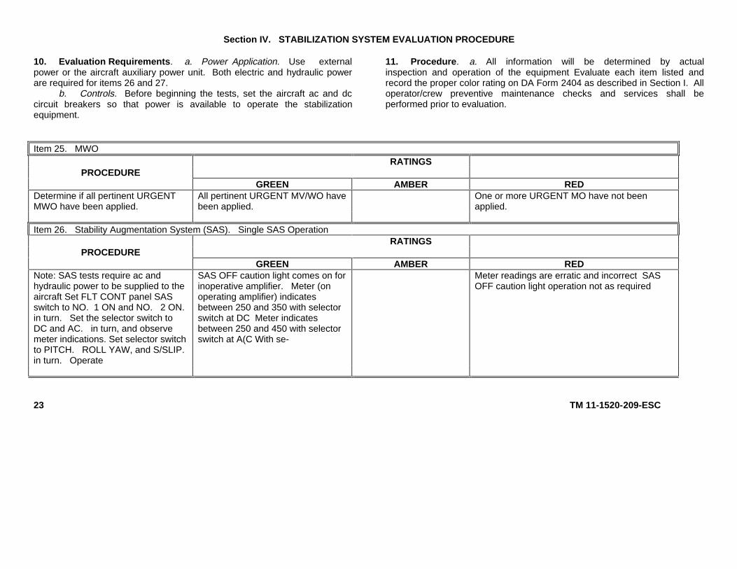
10. Evaluation Requirements. a. Power Application. Use externalpower or the aircraft auxiliary power unit. Both electric and hydraulic powerare required for items 26 and 27.
b. Controls. Before beginning the tests, set the aircraft ac and dccircuit breakers so that power is available to operate the stabilizationequipment.
11. Procedure. a. All information will be determined by actualinspection and operation of the equipment Evaluate each item listed andrecord the proper color rating on DA Form 2404 as described in Section I. Alloperator/crew preventive maintenance checks and services shall beperformed prior to evaluation.
Item 25. MWORATINGS
PROCEDUREGREEN AMBER RED
Determine if all pertinent URGENTMWO have been applied.
All pertinent URGENT MV/WO havebeen applied.
One or more URGENT MO have not beenapplied.
Item 26. Stability Augmentation System (SAS). Single SAS OperationRATINGS
PROCEDUREGREEN AMBER RED
Note: SAS tests require ac andhydraulic power to be supplied to theaircraft Set FLT CONT panel SASswitch to NO. 1 ON and NO. 2 ON.in turn. Set the selector switch toDC and AC. in turn, and observemeter indications. Set selector switchto PITCH. ROLL YAW, and S/SLIP.in turn. Operate
SAS OFF caution light comes on forinoperative amplifier. Meter (onoperating amplifier) indicatesbetween 250 and 350 with selectorswitch at DC Meter indicatesbetween 250 and 450 with selectorswitch at A(C With se-
Meter readings are erratic and incorrect SASOFF caution light operation not as required
23 TM 11-1520-209-ESC
24 TM 11-1520-209-ESC
Item 26. Stability Augmentation System (SAS). Single SAS Operation (Continued)RATINGS
PROCEDUREGREEN AMBER RED
L-R switch alternately to L and R ateach switch position and observemeter indication.
lector switch at PITCH, ROLL andS/SLIP during L-R switch operationmeter pointer moves slowly to avalue between I50 and 350. ForSAS amplifiers 114E3030-40.114E3030-42. and 114E3030-43.meter pointer remains at thatposition. For SAS amplifiers 114E3030-47 and I 14E3030-49.meter pointer slowly returns to 0O.(Record the maximum indication foruse in item 27 ) With selector switchat YAW for SAS amplifiers114E3030-40, -42, and -43. meterpointer moves in the directionindicated by the position of the L-Rswitch Indication then decreases toone-third of the original indicationwithin 3 to 7 seconds. With theselector switch at YAW
Item 26. Stability Augmentation System (SAS), Single SAS Operation (Continued)RATINGS
PROCEDUREGREEN AMBER RED
for SAS amplifier 1 14E3030-47 and-49, meter indicates between 150and 350 in the direction indicated bythe L-R switch and then decreasesto one half the maximum indicationin approximately 7 seconds andholds steady.
Item 27. Stability Augmentation System (SAS), Dual SAS Operation
RATINGSPROCEDURE
GREEN AMBER REDSet FLT CONT panel SAS switch toboth ON and perform test proceduresgiven in item 26 for each SASamplifier
Meter indications for DC and AC arethe same as for single SASoperation. Meter indications forPITCH, ROLL, YAW, and S/SLIPare one-half (* one scale division) ofthe values recorded in item 26.SAS OFF caution light comes on forthe inoperative amplifier.
Meter readings are erratic and incorrect.
25 Change 2 TM 11-1’520-209-ESC
26 TM 11-1520-209-ESC
Item 28. Speed Trim FacilityRATINGS
PROCEDUREGREEN AMBER RED
Set the speed trim amplifier selectorswitch to AC, B+, and MAN; for eachswitch position set, observe meterindications. Set selector switch toA/S, FWD, and AFT and, in turn,press the PRESS TO TEST switch ineach switch position. Observe meterindications.
With selector switch at AC and B+,meter indicates between 0.7 and0.9. At MAN, meter indicatesbetween 0.5 and 0.9 for maximumforward trim wheel position, 0.0 to0.1 for maximum aft position, and0.3 to 0.4 for 0 position. At FWDand AFT, meter indicates 0; pressthe PRESS TO TEST switch, meterindicates approximately 0.5. Forspeed trim amplifier 114E2186-23or 114E218626, with selector switchat AS, meter indicates a maximumof 0.1. Press the PRESS TO TESTswitch; meter indicates greater than0.1. For speed trim amplifier114E2186 30, with selector switchat AS, meter indicates a maximumof 0.3. Press the
Meter readings are erratic and incorrect
Item 28. Speed Trim Facility (Continued)RATINGS
PROCEDUREGREEN AMBER RED
PRESS TO TEST switch; meterindicates greater than 0.3.
Note: The AC position is not wiredin speed trim amplifier 114E2186-30.
b. Rating for Stabilization System. The color rating will be the lowest rating recorded above.
Section V. AUXILIARY SYSTEM EVALUATION PROCEDURE
12. Evaluation Requirements. a. Power Application. Use externalpower or the aircraft auxiliary power unit for item 30.
b. Controls. Before beginning the tests, set the aircraft ac and dccircuit breakers so that power is available to operate the Proximity WarningSystem.
13. Procedure. a. All information will be determined by actualinspection and operation of the equipment. Evaluate each item listed andrecord the proper color rating on DA Form 2404 as described in Section I. Alloperator/crew preventive maintenance checks and services shall beperformed prior to evaluation.
Item 29. MWORATINGS
PROCEDUREGREEN AMBER RED
Determine if all pertinent URGENTMWO have been applied.
All pertinent URGENT MWO havebeen applied.
One or more URGENT MWO have not beenapplied.
27 Change 1 TM 11-1520-209-ESC
28 Change 1 TM 11-1520-209-ESC
Item 30. Proximity Warning SystemRATINGS
PROCEDUREGREEN AMBER RED
Set the Proximity Warning SystemTRANSPONDER GND TEST/CONFIDENCE TEST SWITCH TOCONFIDENCE TEST
Note: The ABOVE. EQUAL. andBELOW lamps normally light andcycle one time when power is initiallyapplied.
Receiver-Transponder ABOVE,EQUAL and BELOW indicatorlamps light in cycle.
Audio alarm is heard in the pilot’sand copilot’s headsets.
Receiver-Transponder ABOVE, EQUAL orBELOW indicator lamps do not light.
Audio alarm not heard in pilot’s and copilot’sheadsets.
b. Ratings for Auxiliary System. The color rating will be the lowest rating recorded above
By Order of the Secretary of the Army:
CREIGHTON W. ABRAMSGeneral, United States Army
Official: Chief of Staff
VERNE L. BOWERSMajor General, United States Army
The Adjutant General
DISTRIBUTION:To be distributed in accordance with DA Form 12-31, Organizational maintenance requirements for CH-47A, CH-47B, and C aircrafts.
*U.S. GOVERNMENT PRINTING OFFICE: 1991 293-761 TM 11-1520-209-ESC
PIN NO: 028810
This fine document...
Was brought to you by me:
Liberated Manuals -- free army and government manuals
Why do I do it? I am tired of sleazy CD-ROM sellers, who take publicly available information, slap “watermarks” and other junk on it, and sell it. Those masters of search engine manipulation make sure that their sites that sell free information, come up first in search engines. They did not create it... They did not even scan it... Why should they get your money? Why are not letting you give those free manuals to your friends?
I am setting this document FREE. This document was made by the US Government and is NOT protected by Copyright. Feel free to share, republish, sell and so on.
I am not asking you for donations, fees or handouts. If you can, please provide a link to liberatedmanuals.com, so that free manuals come up first in search engines:
<A HREF=http://www.liberatedmanuals.com/>Free Military and Government Manuals</A>