45
INNOMETRIKS INC Rhino Implementation Guide
| Date post: | 24-Apr-2018 |
| Category: |
Documents |
| Upload: | truongquynh |
| View: | 223 times |
| Download: | 0 times |

INNOMETRIKS INC
Rhino Implementation
Guide

Rhino Implementation Guide
Innometriks Inc Fallbrook, Ca. 92028 Phone 760-542-0200
Sales: [email protected]
General Information: [email protected] Customer Support: [email protected]
Copyright Copyright © 2010 by Innometriks Inc. All rights reserved. Trademarks The Rhino is a trademark of Innometriks Inc. All other product names used are trademarks of their respective owners. Notice The material in this document is for information only and is subject to change without notice. While reasonable efforts have been made in the preparation of this document to assure its accuracy, Innometriks Inc. assumes no liability resulting from errors or omissions in this document, or from the use of the information contained herein. Innometriks reserves the right to make changes in the product design without reservation and without notification to its users.

R H I N O I M P L E M E N T A T I O N G U I D E R E V 2 . 0
Table of Contents
THE INNOMETRIKS SOLUTION......................................................................................................................... 1 STRONG IDENTITY AUTHENTICATION...................................................................................................................................... 1 WHAT MAKES INNOMETRIKS DIFFERENT .............................................................................................................................. 1 THE RHINO.................................................................................................................................................................................... 1
INSTALLATION AND WIRING ............................................................................................................................ 2 PHYSICAL DESCRIPTION ............................................................................................................................................................. 2 POWER REQUIREMENTS ............................................................................................................................................................. 4 POWER CABLING .......................................................................................................................................................................... 4 READER COMMUNICATION......................................................................................................................................................... 4 MOLEX CONNECTOR WIRING .................................................................................................................................................... 5 INPUT/OUTPUT CONNECTIONS................................................................................................................................................. 6
NETWORK ENVIRONMENT ................................................................................................................................ 8 PLANNING...................................................................................................................................................................................... 8 READER CONFIGURATION .......................................................................................................................................................... 9 SETTING ETHERNET PARAMETERS ........................................................................................................................................10
APPLICATION ENVIRONMENT ........................................................................................................................14 INSTALLING RHINO READER AND RHINO UPGRADE UTILITIES ........................................................................................14 USING THE RHINO READER UTILITY ......................................................................................................................................14 RHINO READER UTILITY > SETTINGS ....................................................................................................................................16 RHINO READER UTILITY > SETTINGS > ADVANCED ...........................................................................................................19 RHINO READER UTILITY > ENROLLMENTS...........................................................................................................................33 RHINO READER UTILITY > ADMINISTRATORS .....................................................................................................................35 RHINO READER UTILITY > REPORTS .....................................................................................................................................35 RHINO READER UTILITY > BIOMETRICS ...............................................................................................................................36 RHINO READER UTILITY > QUICK SET...................................................................................................................................36 FACTORY RESET .........................................................................................................................................................................36 USING THE RHINO UPGRADE UTILITY ...................................................................................................................................37 ADDITIONAL READER ADMINISTRATIVE INTERFACE FEATURES .....................................................................................38
APPENDIX ..............................................................................................................................................................42

R H I N O I M P L E M E N T A T I O N G U I D E R E V 2 . 0
1
The Innometriks Solution
Strong Identity Authentication
Innometriks develops and manufactures a suite of hardware and software products that provide strong identity authentication for mission critical environments. Strong identity authentication verifies an individual’s identity using technologies including biometrics, smartcards, Public Key Infrastructure (PKI) and digital signatures to provide a level of assurance above and beyond that available through simple PIN, password or non-smartcard ID card mechanisms. Strong identity authentication provides greater protection of critical assets and sensitive information.
The Company’s strong identity authentication offerings fill critical compliance gaps that exist in current generation physical access control systems (PACS). Although fully functional and well within their operational life span, most installed PACS fail to meet the credential verification and identity authentication requirements set forth by the U.S. Government identity programs known as Personal Identity Verification (PIV) and Transportation Workers Identity Credential (TWIC). Innometriks also offers a scalable “matching” biometric authentication solution tailored for commercial facility security, time and attendance and other applications where positive identity of individuals is of paramount importance.
What Makes Innometriks Different
Innometriks’ Products complement, not compete against, existing physical access control solutions. Innometriks offerings fill critical compliance gaps that exist in current generation physical access control systems. This strategy provides security specialist, managing a large non-compliant physical access control systems, with the optimal upgrade path that meets all compliance requirements.
The Rhino
The Rhino is implemented on an open source Linux platform, providing unprecedented flexibility in integrator and end user customization. Each Rhino configuration is packaged in an extremely durable metal housing engineered for harsh operating environments. The Rhino offers flexible configuration options for fingerprint sensors, environmental implementation (waterproof housing & enclosure heaters) and system connectivity (Ethernet, RS485, and industry standard Wiegand interfaces). Further, the Rhino line features bright, easy to read color displays and multifunction keypads that deliver a pleasant user experience.
This unique device is designed from the ground up to be easy to deploy, flexible and secure, providing security conscience organizations with a strong authentication solutions for physical access.

R H I N O I M P L E M E N T A T I O N G U I D E R E V 2 . 0
2
Installation and Wiring
Physical Description
Dimensions:
• Length: 10.31”
• Width: 5.94”
• Depth: 3.94”
• Weight: ~ 4lbs
• Material: Aluminum

R H I N O I M P L E M E N T A T I O N G U I D E R E V 2 . 0
3

R H I N O I M P L E M E N T A T I O N G U I D E R E V 2 . 0
4
Connections
Power Requirements
The Rhino reader requires nominally 12VDC at 750 milliamps to operate correctly. The Rhino installed with the heater option for extreme outdoor conditions requires nominally 12VDC at 3amps to operate correctly. The wiring to deliver power to the reader should conform to proper electrical installation practices and codes, and should be of a gauge required to deliver the required voltage and current to the reader without excessive loss or heating.
Power Cabling
Innometriks recommends power cabling of no less than 18 gauge be used for installation of standard (none heater) Rhino devices.
The table below provides some guidance for standard stranded cabling with respect to distance, gauge and current (at 12VDC) and can be used to select the proper cable for powering the units.
Total Branch Current in mA
Wire Gauge 250 500 1000 1500 2000 2500 3000 3500
12 3023 1511 756 504 378 302 252 216
14 1901 950 475 317 238 190 158 136
16 1194 597 299 199 149 119 100 85
18 751 376 188 125 94 75 63 54
Maximum distance in feet
Reader Communication
Communications for the reader will be handled either via a CAT5 cable or RS485. When connecting via Ethernet, standard Ethernet cables should be used and standard Ethernet distances should be adhered to. For RS485 communications standard CAT5 cable, a twisted pair 24AWG wire, can be used. It is also possible that a stranded cable can be used. In either case however it is recommended in a noisy environment that a shielded cable be utilized.
For Wiegand communications it is recommended that you consider your environment to determine the need for shielded cable. The Rhino reader has the ability to send and receive Wiegand data. Wiegand output is typically used to send authentication data to a PACS panel. Wiegand input allows the reader to accept input from external Wiegand devices like a magnetic stripe reader. It is recommended that you

R H I N O I M P L E M E N T A T I O N G U I D E R E V 2 . 0
5
adhere to standard Wiegand distance limitations of 500 feet and would use twisted pair cable from 20AWG to 24AWG.
In addition TTL input provides a way to accept single or dual LED return, typically called Green LED and Red LED/Buzzer to provide user feedback such as Access Granted, Access Denied, and Enter PIN. TTL output provides a means of adding external authentication status devices such as stack lights.
Molex Connector Wiring
It is best to wire both the Molex input/output and power connectors while they are free of the Rhino unit.
Input/Output Connector
Power Connector

R H I N O I M P L E M E N T A T I O N G U I D E R E V 2 . 0
6
Rhino board level view of connections
Input/Output Connections
RS485
The EIA-485 differential line consists of two pins:
Pin 1 RS485-A, '−', TxD-/RxD-, or inverting pin
Pin 2 RS485-B, '+', TxD+/RxD+, or non-inverting pin
Wiegand
The reader interface uses standard Wiegand wiring conventions. The Rhino reader uses Wiegand Out to send data to the PACS panel, and Wiegand In to receive data from an external device such as a magnetic stripe reader. Connect the wire properly to the terminal block on the appropriate board node. Following is a typical, but not universal, wiring guide. Refer to the Panel/Reader/Keypad Wiring Guide for guidelines related to your specific PACS, reader or keypad.
Pin 3 Ground for Wiegand Input Device – Typically black external input device wire. Ground for Rhino 5 VDC power for external Wiegand input devices.
Pin 4 Power for Wiegand Input Device - Typically Red external input device wire. Supplies 5 VDC power for external Wiegand input devices.

R H I N O I M P L E M E N T A T I O N G U I D E R E V 2 . 0
7
Pin 5 Wiegand In 0 - Typically orange reader wire to the DATA0 terminal. Used to receive data from an external Wiegand input device.
Pin 6 Wiegand In 1 - Typically brown reader wire to the DATA1 terminal. Used to receive data from an external Wiegand input device.
Pin 7 Wiegand Out 1 - Typically green reader wire to the DATA1 aka W1 aka Data Low terminal. Used to send data to a PACS panel or other external device.
Pin 8 Wiegand Out 0 - Typically white reader wire to the DATA0 aka W0 aka Data High terminal. Used to send data to a PACS panel or other external device.
TTL
TTL Out is typically used to convey authentication status to TTL LEDs, light stacks or other compatible devices. TTL In is typically used to pass single or dual PACS panel Pass/Fail/PIN output back to the reader. Pin 9 TTL Out 1 – Active low Pin 10 TTL Out 2 – Active low Pin 11 TTL In 1 – Active high Pin 12 TTL In 2 – Active high
Relay
Relay Open/Close is typically used in environments where the reader is used independent of a PACS system. Relay can be used to directly control magnetic and electric strikes. Pin 13 RLY CO or Common – Relay common Pin 14 RLY NO or normally open – Example, electric door strike Pin 15 RLY NC or normally closed – Example, magnetic door strike
Ground
The ground pin should be connected to the PACS panel ground. Reader to panel communication issues are often traced back to an improper panel ground. PLEASE CONNECT TO PANEL GROUND. Pin 16 GND, Ground or Common – Black external reader wire

R H I N O I M P L E M E N T A T I O N G U I D E R E V 2 . 0
8
Network Environment
Planning
Innometriks Application suite communicates with the Rhino reader via Ethernet, RS485 or USB. In most environments, Rhino readers will be geographically dispersed across buildings and security gate entrances, and utilize an Ethernet communication backbone. Network based reader configuration, firmware upgrades and server communication requires each reader be correctly configured to match the environment that it is deployed in. Required Ethernet network settings include:
• Static IP address for each reader • Subnet Mask • Gateway Address (if needed) • Local Port (default 5001)
Note: In environments with multiple network segments, all intermediate routers and switches must be set to forward TCP port 5001, 5002, 5003, and 5004.

R H I N O I M P L E M E N T A T I O N G U I D E R E V 2 . 0
9
Additional network settings must be defined for Innometriks applications that require the reader to communicate back to a server. Innometriks provides application specific guidelines that indicate if these additional settings are required:
• Server Address where Innometriks processes run • Event Server Port (default 5002) • Image Server Port (default 5003) • Template Server Port (default 5004)
Every Rhino reader manufactured has a unique Media Access Control address (MAC address) assigned to its network adapter. In secure network environments where MAC addresses are used to restrict network access, the MAC of each Rhino reader should be documented and given to a network security administrator. Reader MAC address can be found under Network Settings on the Rhino Administration interface. See the Configuring Ethernet settings at the reader section below.
Reader Configuration
Setting configuration values on the Rhino is accomplished using:
1. The Windows based Rhino Reader Utility (Rhino.exe), or
2. The Rhino administration feature imbedded on every Rhino reader
These interfaces allow an administrator to configure all Rhino settings including these key parameters:
• Operation Mode – Example: Identify, Identify plus PIN, Card plus Biometric, etc • Ethernet settings • PACS panel interface settings – Wiegand in, Wiegand out, Pass/Fail functions, etc. • Card reader settings – Card type, data format, etc. • Biometric settings • Event logging
The Rhino Reader Utility:

R H I N O I M P L E M E N T A T I O N G U I D E R E V 2 . 0
10
The Rhino administration interface – accessed by pressing and holding * on the keypad:
Both administration interfaces should be secured. Run the Windows based Rhino Reader Utility from a secure Windows account that is password protected. Access to the Rhino Administration interface can be limited to a list of approved people who are authenticated via biometric fingerprint and PIN.
NOTE: When the Rhino administrative interface is in use, the reader cannot be accessed using the Rhino Reader Utility (Rhino.exe)
Setting Ethernet Parameters
For each new reader, Rhino Ethernet parameters must be set before using the Windows based Rhino Reader Utility to complete the configuration across a TCP/IP network connection. Ethernet parameters can be set one of two ways.
1. Use a direct USB connection between the reader and a PC running the Rhino Reader Utility.
2. Set the Ethernet parameters directly at the reader using the Rhino administration interface.
Setting the parameters at the reader is the recommended route given its simplicity. When deploying large implementations, configuring at the reader allows units to be wired in place and basic setting defined without the need for first moving all readers to one central location.
Configuring Ethernet settings at the reader:
1. Make sure the reader is properly wired for 12 VDC power (see “Power Cabling” section above)
2. Make sure the reader is properly wired to the network (see “Reader Communication” section above)
3. Determine the correct settings for the reader (from the “Network Planning” section above)
4. A fully booted reader should display a user interface specific to your application (touch sensor, present card, etc). For example:

R H I N O I M P L E M E N T A T I O N G U I D E R E V 2 . 0
11
5. Press and hold the * on the keypad. You should see the following screen:
6. Press the left hand soft-key below the “plus” icon. You should see the following screen:
7. Verify that Network is set to Ethernet. If not, use the soft-key under the “down arrow” to highlight network, and use the “plus” to set network to Ethernet. Use the soft-key under the “back-step” icon to return to the Administrator Menu:

R H I N O I M P L E M E N T A T I O N G U I D E R E V 2 . 0
12
8. Press the down-arrow once and then + to enter the Operational Parameter menu. You should see the following screen:
9. Use the down-arrow and then + to enter the Network settings menu.
Required network settings include:
• Static IP address for each reader • Subnet Mask

R H I N O I M P L E M E N T A T I O N G U I D E R E V 2 . 0
13
• Gateway Address (if needed) • Local Port (default 5001)
Note: In environments with multiple network segments, all intermediate routers and switches must be set to forward TCP port 5001, 5002, 5003, and 5004.
Additional network settings must be defined for Innometriks applications that require the reader to communicate back to a server. Innometriks provides application specific guidelines that indicate if these additional settings are required:
• Server Address where Innometriks processes run • Event Server Port (default 5002) • Image Server Port (default 5003) • Template Server Port (default 5004)
Once the network settings have been defined, press the soft-key under the “back-step” icon to navigate back up the menu tree and user mode. The unit does not need to be reset or repowered, the new network setting take effect immediately.
Although the Rhino may be fully configured at the reader using the Administration interface, once the TCP/IP settings are defined it may be more efficient to use the Rhino Reader utility to complete the configuration.

R H I N O I M P L E M E N T A T I O N G U I D E R E V 2 . 0
14
Application Environment
Installing Rhino Reader and Rhino Upgrade Utilities
The Rhino Reader Utility is a Microsoft Windows based admin tool that provides reader management across the network. Security administrators use this utility to manage readers distributed throughout one or more buildings, across a campus or a secure compound.
In addition, a separate utility called Rhino Upgrade provides a way for administrators to upgrade the reader kernel and reader application firmware across the network. This robust utility transfers a new image package to the reader where verification and installation occurs. Package verification and image installation is triggered automatically at the reader, freeing the administrator to upgrade the next reader in the chain.
There is no need to perform an installation. You simply place the Rhino.exe, RhinoUpgrade.exe, RhinoLib.dll and Rhino USB driver images in the same folder location. Typically;
C:\Program Files\Innometriks\Rhino
Create a shortcut to Rhino.exe and RhinoUpgrade.exe on your desktop. If you connect a Rhino direct via USB, browse to the USB driver location the first time you connect a reader to your Windows environment. Rhino.exe will create all required application folders and files.
As mention in the Setting Ethernet Parameters section above, Ethernet parameters can be set using a direct USB connection instead of the Rhino Administration interface at the reader. Once network parameters are configured, all Rhino settings can be configured across the network. To configure;
• Launch Rino.exe • With the Rhino unit powered up, connect to the Rhino via USB • Allow USB drivers to load
The Rhino will drop into a USB Command Mode.
If not, the “Auto” USB parameter must be set directly at the reader using the Rhino administration interface, accessed by pressing and holding * on the keypad. Reader Administration Interface > Operational Setup > USB Connection: “Auto”.
The following section describes how set and save reader parameters.
Using the Rhino Reader Utility
Administrators must first create a list of the readers on the network, and associate a network address with each location name. To add a reader to the list:
Menu Bar > Setup > Add Unit

R H I N O I M P L E M E N T A T I O N G U I D E R E V 2 . 0
15
Setting reader parameters using the Rhino Reader Utility typically follows a sequence of steps;
1. Establish a Connection to a reader using the lower left controls - typically TCP/IP.
2. Select a Portal from the list of radio buttons provided on the upper right - typically “Settings”.

R H I N O I M P L E M E N T A T I O N G U I D E R E V 2 . 0
16
3. “Pull Current” reader settings using the Sync controls mid-left.
4. Make intended changes to the parameters.
5. “Push Updates” the changes back out to the reader using Sync controls
Rhino Reader Utility > Settings
Operation
Defines the authentication mode of the reader. This setting is typically changed to match changes in threat levels. The options available on a given reader, depends on the implementation and the authentication goals. Examples include:
• Identify Only • Identify + PIN • Card Number + Finger • ICLASS Card • DESFIRE Card • PIV CARD + Finger • TWIC CARD + Finger
Details on modes available in each of the Innometriks products can be found in the Appendix.
Media
The Rhino reader uses onboard flash memory for operation. SD card memory expansion is offered as an option that provides 2 gigabytes of addition storage for large image databases. The two media options are:
• System Flash • SD Card

R H I N O I M P L E M E N T A T I O N G U I D E R E V 2 . 0
17
Set to SD Card if the reader has the optional SD memory expansion installed. Otherwise set to System Flash.
Panel Interface
Bi-directional communication between a reader and the physical access control system occurs through the panel interface. Selecting “on” simply enables the panel interface. Panel communication specifics are set using the Advanced > Panel dialog, and the Advanced > Wiegand dialog. Options available:
• On • Off
Network Connection
This setting enables network communication and is typically set to Ethernet or RS485 depending on the network infrastructure present. If security policy mandates network isolation, set the reader to “None”. Options available:
• None • Ethernet • RS485
USB Connection
A USB port is available for connecting a reader directly to a PC, allowing an administrator to set reader parameters. Options available:
• Off • Manual • Auto
Off is used to isolate the reader from all USB communication. Manual allows a USB connection to be initiated from the Rhino Reader Utility. When set to auto, the reader will immediately drop into the USB administration mode whenever a USB cable is connected. Auto streamlines the process of configuring readers using the Rhino Reader Utility via a direct USB connection.
Lock Control
Lock control allows the reader to trigger external relays. This feature is very useful for securing remote gates in environments without a physical access control system (PACs). Door relays can be opened and closed based on the outcome of authentication event. In addition, external relays can be triggered in response to Wiegand and TTL input from a PACs panel. This feature facilitates “man-trap” and “lock down” functionality. Selecting “on” simply enables lock control. Lock control specifics are set using the Advanced > Lock dialog. Options available:
• On • Off

R H I N O I M P L E M E N T A T I O N G U I D E R E V 2 . 0
18
Event Logging
Event Logging tracks authentication outcome, firmware upgrade events, and communication and process failures. Tracking provides administrators with a detailed history of what has occurred at a reader. Types of events logged is defined using the Advanced > Log dialog. Logs can be maintained locally, at the network server level, or both. Options available:
• Media • Network • Media and Network
Duress
The duress features ties the reader keypad “*” character to a security alert communication path. If an individual is forced to authenticate at a reader against their will, the duress key allows them to silently alert security officials. The key is mapped to a Wiegand output, TTL output or relay element. Selecting “on” simply enables the duress interface. Duress communication specifics are set using the Advanced > Duress dialog. Options available:
• On • Off
Language
The Rhino reader supports a growing list of language sets. Current options available:
• English • Espanol • Francais
Administrator
The reader administration mode is accessed by pressing and holding the * on the keypad. To secure the reader and limit access to the administration mode, one or more individuals must be enrolled as “administrators” and this parameter must be set to “on”. Administrators are enrolled using Portals > Administrators, and are authenticated using two factor PIN + biometric fingerprint. Options available:
• On • Off
Site Number & Site Name
Site Number and Site Name allow an Administrator to assign identification attributes to each reader in multi-reader environments. Values assigned are at the discretion of the site administrator.

R H I N O I M P L E M E N T A T I O N G U I D E R E V 2 . 0
19
Reader Administration Interface > Operational Setup
The reader settings described above can also be set directly at the reader using the Rhino administration interface, accessed by pressing and holding * on the keypad.
Rhino Reader Utility > Settings > Advanced
Panel
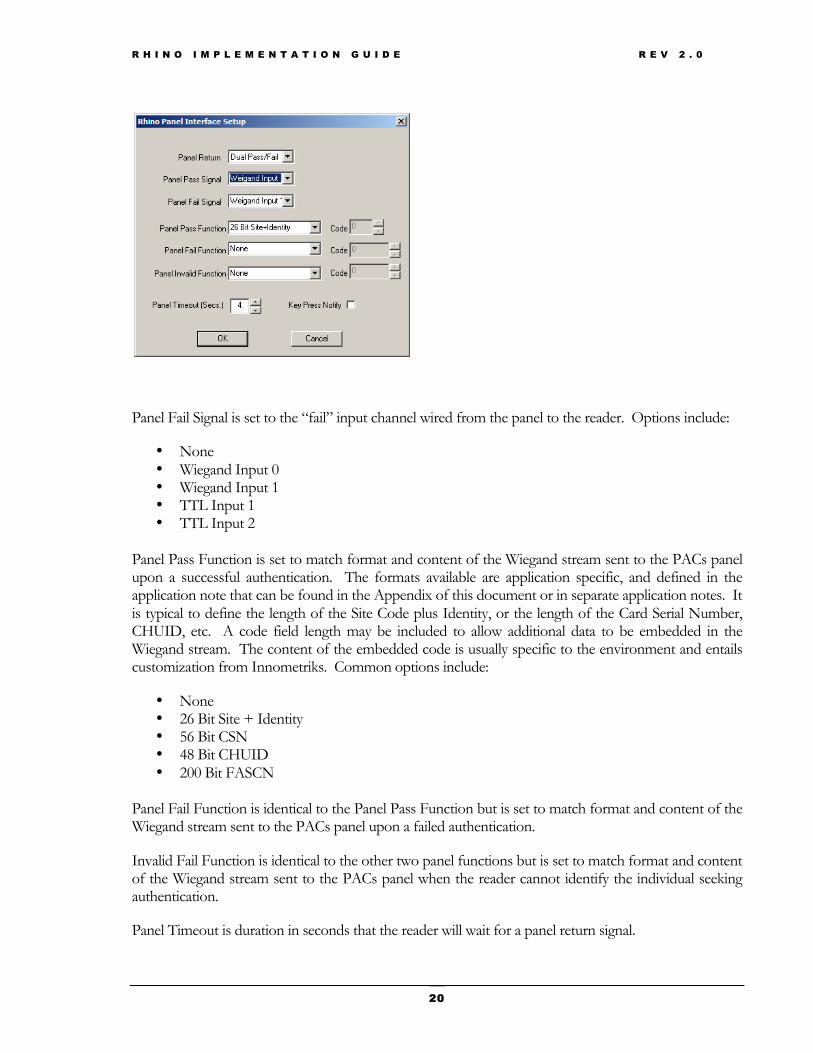
Bi-directional communication between a reader and the physical access control system occurs through the panel interface. These settings configure the reader to match the communication expectations of the PACs panel and PACs host application. The reader is also configured to properly handle the return communication from the PACs.
Panel Return is set to match response from the PACs panel after an authentication outcome is sent. Single and dual match the wiring configuration between the panel and the reader. Pass and Fail allows the reader to provide feedback to the user requesting access. The user may authenticate successfully at the reader, but not have PACs set rights to enter the protected portal. PIN triggers the reader to prompt for a PACs defined PIN for two factor authentication. Options include:
• None • Dual Pass/Fail • Dual Pass/Fail/PIN • Single Pass/Fail • Single Pass/Fail/PIN
Panel Pass Signal is set to the “pass” input channel wired from the panel to the reader. Options include:
• None • Wiegand Input 0 • Wiegand Input 1 • TTL Input 1 • TTL Input 2
R H I N O I M P L E M E N T A T I O N G U I D E R E V 2 . 0
20
Panel Fail Signal is set to the “fail” input channel wired from the panel to the reader. Options include:
• None • Wiegand Input 0 • Wiegand Input 1 • TTL Input 1 • TTL Input 2
Panel Pass Function is set to match format and content of the Wiegand stream sent to the PACs panel upon a successful authentication. The formats available are application specific, and defined in the application note that can be found in the Appendix of this document or in separate application notes. It is typical to define the length of the Site Code plus Identity, or the length of the Card Serial Number, CHUID, etc. A code field length may be included to allow additional data to be embedded in the Wiegand stream. The content of the embedded code is usually specific to the environment and entails customization from Innometriks. Common options include:
• None • 26 Bit Site + Identity • 56 Bit CSN • 48 Bit CHUID • 200 Bit FASCN
Panel Fail Function is identical to the Panel Pass Function but is set to match format and content of the Wiegand stream sent to the PACs panel upon a failed authentication.
Invalid Fail Function is identical to the other two panel functions but is set to match format and content of the Wiegand stream sent to the PACs panel when the reader cannot identify the individual seeking authentication.
Panel Timeout is duration in seconds that the reader will wait for a panel return signal.

R H I N O I M P L E M E N T A T I O N G U I D E R E V 2 . 0
21
Key Press Notify forwards reader keypad entry to the PACs allowing commands to be passed from the reader to the PACS panel. Use requires PACs support of this feature.
Reader Administration Interface > Operational Parameters > Panel Interface
Biometrics
The Rhino reader utilizes two of the finest biometrics sensors on the market, the Lumidigm and the Futronic. To maximize the potential of these two readers, Innometriks exposes sensor-tuning options to allow readers to be matched to security requirements, environmental conditions and/or user demographics.

R H I N O I M P L E M E N T A T I O N G U I D E R E V 2 . 0
22
Enrollment Method defines the preferred number of templates captured at enrollment. Using dual enrollments merges the templates to reduce file size (single header), and file management demands. Options include:
• Single Template • Merged Dual Templates • Separate Dual Templates
Security is tied to the match score generated when a fingerprint is compared to a template. The higher the security level, the higher the threshold is for a “pass” authentication. Options include:
• Normal • Enhanced • Maximum
Quality Threshold determines the minimum number of minutia data points that’s acceptable in a captured fingerprint. Options include:
• Low • Medium • High
Rotational Level sets the tolerance for a skewed or off-axis finger placement during authentication. Options include:
• Low tolerance • Medium tolerance • High tolerance
Sensor Sensitivity is tied to finger presence detection and determines when a sensor attempts to capture a fingerprint. Options include:
• High • Normal
Sensor Timeout is the length of time in seconds that a sensor will attempt to capture a fingerprint.
Retry on fail determines if a user is given a second chance to authenticate.
Performance is determines the resolution of the fingerprint capture. Options include:
• High Accuracy – Highest resolution, slowest capture • Accuracy and Speed – Normal resolution • High Speed – Lowest resolution, fast capture
Spoof Detection is a future feature enhancement.

R H I N O I M P L E M E N T A T I O N G U I D E R E V 2 . 0
23
Reader Administration Interface > Operational Parameters > Biometrics
RS485
If RS485 communication is the preferred network infrastructure, a readers RS485 network setting are defined here. Options include:
Network Address is set to a unique integer value
Baud Rate
• 9600 • 19200 • 38400 • 57600
Stop Bits
• One • Two

R H I N O I M P L E M E N T A T I O N G U I D E R E V 2 . 0
24
Reader Administration Interface > Operational Parameters > RS485
Ethernet
Readers utilizing Ethernet for host communication, configuration and upgrade, must have the following settings defined:
• Static IP address unique to each reader • Subnet Mask • Gateway Address (if needed) • Local Port (default 5001)

R H I N O I M P L E M E N T A T I O N G U I D E R E V 2 . 0
25
Note: In environments with multiple network segments, all intermediate routers and switches must be set to forward TCP port 5001, 5002, 5003, and 5004.
Additional network settings must be defined for Innometriks applications that require the reader to communicate back to a server. Innometriks provides application specific guidelines that indicate if these additional settings are required:
• Server Address where Innometriks processes run • Event Server Port (default 5002) • Image Server Port (default 5003) • Template Server Port (default 5004)
Every Rhino reader manufactured has a unique Media Access Control address (MAC address) assigned to its network adapter. In secure network environment where MAC addresses are used to restrict network access, the MAC from each Rhino reader should be documented and turned over to the network security administrator.
Reader Administration Interface > Operational Parameters > Ethernet
Lock
Lock control allows the reader to trigger external relays. This feature is very useful for securing remote gates and in environments without a physical access control system (PACs). Door relays can be opened and closed based on the outcome of authentication event.
In environments where the reader is tied to a PACs, the reader typically passes a users ID along with the authentication pass/fail outcome. The PACs then determines if the user has permission to enter the protected portal. If the reader is in control of the door lock device instead of the PACs panel, input from the PACs panel can set to trigger the “open” or “close” event.
Hold Line disables the reader user interface, effectively blocking new authentication events. When combined with Auto-Open and/or Auto-Close, this feature may be used to facilitate “man-trap” and “lock down” functionality.

R H I N O I M P L E M E N T A T I O N G U I D E R E V 2 . 0
26
Open Line defines the reader output channel that triggers an external device when a successful authentication occurs. Open Line options:
• None
• Relay
• TTL Output 1
• TTL Output 2
Auto-Open Line defines the external input channel that triggers an open line event. Auto-Open Line options:
• None
• Wiegand Input 0
• Wiegand Input 1
• TTL Input 1
• TTL Input 2
Hold Line defines the external input channel that disables the reader user interface. Hold Line options:
• None
• Wiegand Input 0
• Wiegand Input 1
• TTL Input 1
• TTL Input 2

R H I N O I M P L E M E N T A T I O N G U I D E R E V 2 . 0
27
Reader Administration Interface > Operational Parameters > Lock Control
Log
Tracking provides administrators with a detailed history of what has occurred at a reader. The report portal (see RHINO READER UTILITY > REPORTS section) allows an administrator to pull, view and purge logs from a specific reader. This feature is useful when investigating a pattern of failed authentication events. The logs are useful when troubleshooting a reader that is not performing as expected. Event logging tracks:
• User authentication outcome • Administrator authentication outcome • Firmware upgrade events • Communication failures • Process failures • System startup

R H I N O I M P L E M E N T A T I O N G U I D E R E V 2 . 0
28
• Events tracked include: • Event • Identity • Time and Date • Location (reader location define in Settings)
Reader Administration Interface > Event Logging
Duress
The duress features ties a reader keypad “*” character to a security alert communication path. If an individual is forced to authenticate at a reader against their will, the duress key allows them to silently alert security officials. The key is mapped to a Wiegand output, TTL output or relay element.
Currently, the only Duress mode is the “*” key. Duress alert line options:
• None • Wiegand Output 0 • Wiegand Output 1 • TTL Output 1 • TTL Output 2 • Relay

R H I N O I M P L E M E N T A T I O N G U I D E R E V 2 . 0
29
Reader Administration Interface > Operational Parameters > Duress
Cards
The Rhino is capable of reading a wide array of different Smart Card classes. Standard government issued card such as PIV, TWIC and CAC must conform the their respective card specification and card reads, certificate validation and holder authentication capability are embedded in the Innometriks firmware that supports each card type.
Other card classes such as I-Class, Mifare and Desfire, can be configured and secured in a number of ways depending on the environment they implemented in. The Rhino provides card configuration options so that security elements can be defined and data formats mapped.
An all-encompassing card configuration dissertation is beyond the scope of this document. Please contact Innometriks support for assistance with a specific implementation. Sample configuration dialogs include:

R H I N O I M P L E M E N T A T I O N G U I D E R E V 2 . 0
30
Reader Administration Interface > Operational Parameters > Card Reader
Reader administration screens vary based on the card application loaded on the reader. Please consult the details in the correct application appendix.
Wiegand
The Wiegand pulse Data High and Data Low width and period can be tuned to accommodate subtleties in PACs panel design, length of wiring runs, or environmental noise.
Reader Administration Interface > Operational Parameters > Panel Interface > Other Settings > Wiegand Setup
Timings
When an authentication event occurs, the outcome is displayed on the reader display to provide user feedback. The outcome display durations can be tuned for a given environment.
• Pass – Authentication successful • Fail – Authentication failed • Invalid – Unreadable fingerprint. User card or PIN not recognized

R H I N O I M P L E M E N T A T I O N G U I D E R E V 2 . 0
31
Reader Administration Interface > Operational Parameters > Timings
Display
Allows an administrator to change the background color of the reader user interface. In addition, display of the time and date can be turned on and off, and the reader display brightness and contrast can be changed. Color options include:
• Red • Blue • Green • Yellow • UT Orange • Black

R H I N O I M P L E M E N T A T I O N G U I D E R E V 2 . 0
32
Reader Administration Interface > Operational Parameters > Other Settings > Display
Keypad
The Rhino reader keypad has an integral back light for low light illumination. The default setting for the back light is off. In addition, the reader responds to keypad entry with a audible sounder “beep”. The sounder may be turned off using the Reader Administration Interface.
Reader Administration Interface > Operational Parameters > Other Settings > Keypad

R H I N O I M P L E M E N T A T I O N G U I D E R E V 2 . 0
33
Rhino Reader Utility > Enrollments
Innometriks offers a number of different options for the creation and management of user enrollments. Large-scale user provisioning and enrollment management is application based and typically layered on a relational database infrastructure. PIV and TWIC environments require the harvesting of card holder data, including PIN protected information such as photographs and biometric templates. In biometric matching applications, biometric template creation may utilize a dedicated Rhino reader, or utilize separate USB biometric sensor.
Environments with a limited number of readers and a limited number of users may use the Rhino Reader Utility or the reader administration interface to enroll and manage users.
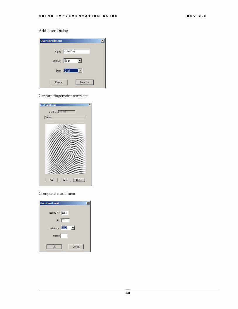
Enrollments typically include:
• Name of individual being enrolled • A unique User ID that is typically tied to a PACs User ID • A PIN that allows for elevated two (biometric + PIN) or three (biometric + card + PIN)
factor authentication.
In addition, administrators may select from single (one finger) or dual (two finger) biometric enrollment. Templates are typically scanned live during the enrollment process. A users templates may also be imported from a ANSI standard template file.
Innometriks allows an Administrator to set usage limitation on a users enrollment that defines how many time they authenticate. This feature is useful for managing temporary access to a facility.
R H I N O I M P L E M E N T A T I O N G U I D E R E V 2 . 0
34
Add User Dialog
Capture fingerprint template
Complete enrollment

R H I N O I M P L E M E N T A T I O N G U I D E R E V 2 . 0
35
Rhino Reader Utility > Administrators
Rhino reader administration mode is accessed by pressing and holding the * on the keypad. To secure the reader and limit access to the administration mode, one or more individuals must be enrolled as administrators and this parameter must be set to “on”. Administrators are enrolled using Portals > Administrators, and are authenticated using two factor PIN + biometric fingerprint.
Add Administrator Dialog
Rhino Reader Utility > Reports
Event logging tracks authentication outcome, firmware upgrade events, and communication and process failures. Tracking provides administrators with a detailed history of what has occurred at a reader. Types of events logged is defined using the Advanced > Log dialog. The report portal allows an administrator to pull, view and purge logs from a specific reader. This feature is useful when investigating a pattern of failed authentication events. It is also useful when troubleshooting a reader that is not performing as expected.

R H I N O I M P L E M E N T A T I O N G U I D E R E V 2 . 0
36
Rhino Reader Utility > Biometrics
The biometrics portal is a useful utility for capturing biometric templates, saving captured templates in a variety of file formats, and comparing a captured fingerprint against a saved template file. It is also useful when evaluating individual enrollment issues caused by thin or worn prints, cuts, burns, etc.
Rhino Reader Utility > Quick Set
Date Stamp
Updates the day, date and time displayed on the reader user interface. The connected reader is updated immediately. A “Push Update” is not required.
Display Color
Sets the background color of the Reader user interface. The connected reader is updated immediately. A “Push Update” is not required. Options include:
• Red • Blue • Green • Yellow • Orange • Black
The Rhino Display Setup section describes additional display and time and date options.
Factory Reset
The Sync > Factory Reset option clears all current reader settings. This feature removes all sensitive parameters and enrollments and is useful when a reader is removed from a secure environment.

R H I N O I M P L E M E N T A T I O N G U I D E R E V 2 . 0
37
Using the Rhino Upgrade Utility
As mentioned in the Rhino Reader Utility installation section above, a separate utility called Rhino Upgrade provides a way for administrators to upgrade the reader kernel and application firmware across the network.
Updating a reader requires this sequence of steps;
1. Launch the utility and select Ramdisk or Kernel
2. Establish a Connection to a reader - typically TCP/IP. The Rhino Upgrade utilizes the Rhino Reader Utility list of the readers on the network, and associated network address.
3. Press Upgrade
4. Navigate to the location of the new Ramdisk ( *.gz ), or Kernel (zImage)
This robust utility transfers a new image package to the reader where verification and installation occurs. Package verification and image installation is triggered automatically at the reader, freeing the administrator to upgrade the next reader in the chain.

R H I N O I M P L E M E N T A T I O N G U I D E R E V 2 . 0
38
Additional Reader Administrative Interface Features
Reader Administration Interface >
In addition to using the Rhino Reader Utility, the reader settings described above can also be set directly at the reader using the Rhino administration interface, accessed by pressing and holding * on the keypad. This following section describes utilities and troubleshooting tools that are available only at the reader.
Reader Administration Interface > Utilities and Tools >
User Database
Provides for the management of user enrollments at the reader. Options Include:
• Add New • List All • Delete • Delete All • Validate

R H I N O I M P L E M E N T A T I O N G U I D E R E V 2 . 0
39
Validate is a powerful utility that loops through the entire user database on the reader and compares each users biometric enrollment against itself, thus verifying that all records are correct and that every biometric template is correctly formatted.
Administrators
Provides for the management of administrator enrollments at the reader. The reader administration mode is accessed by pressing and holding the * on the keypad. To secure the reader and limit access to the administration mode, one or more individuals must be enrolled as administrators and the Operational Setup > Administrator parameter must be set to “on”. Administrators are authenticated using two factor PIN + biometric fingerprint. Options Include:
• Add New • Erase All
Event Report
Provides viewing of events and purging of event reports. Options Include:
• List • Erase
Reader Administration Interface > System Information
Provides a summary of the readers’ hardware and software configuration.

R H I N O I M P L E M E N T A T I O N G U I D E R E V 2 . 0
40
Reader Administration Interface > System Testing >
Biometric
This utility tests the reader ability to scan, create a standard template and verify a fingerprint. Options Include:
• Fingerprint Image • Fingerprint Enroll • Fingerprint Verify
Card Reader
This utility tests the card reader embedded in the reader. It prompts the user to present a card, performs a card read, and indicates success or failure.
Wiegand
This utility provides a quick way to test and troubleshoot Wiegand communication connections between the reader and a PACs panel. Input prompts the user to press any number on the reader keypad and then transmits the correct key code out Wiegand line 0. Input waits to receive input on Wiegand line 0, and then displays the incoming value. Pressing the # key exits both test modes. Options Include:
• Output • Input
TTL Input/Output
This utility provides a quick way to test and troubleshoot TTL connections. TTL Input monitors TTL input line one and two for active high, and indicates when a line goes high. TTL Output alternately pulls TTL output line one and two to active low. Pressing any key exist both test modes. TTL Out is typically used to convey authentication status to TTL LEDs, light stacks or to control external relays. TTL In is typically used to pass PACS panel Pass/Fail/PIN output back to the reader. Options Include:

R H I N O I M P L E M E N T A T I O N G U I D E R E V 2 . 0
41
• Input • Output
LED
The I/O board on each reader has three green LEDs’ which are visible just above the Molex 16 pin connector. The LED test sequentially turns each LED on.
Relay
This utility cycles the onboard relay contacts providing a quick way to test and troubleshoot relay connections.
Keypad
This utility tests the readers’ membrane keypad. As each key is pressed, its corresponding value is displayed. Cycling of the keypad backlight is also provided. Options Include:
• Keypad • Light
RS485
This utility provides a quick way to test and troubleshoot RS485 communication connections between the reader and a PAC system. Input prompts the user to press any number on the reader keypad and then transmits the corresponding value. Input monitors the RS485 connection, and displays all incoming data. Pressing the # key exits both test modes. Options Include:
• Output • Input
Reader Administration Interface > System Reset
System Reset clears all current reader settings. This feature removes all sensitive parameters and enrollments and is useful when a reader is removed from a secure environment.

R H I N O I M P L E M E N T A T I O N G U I D E R E V 2 . 0
42
Appendix


