SECTION 22 30 00 PLUMBING EQUIPMENT BASED ON DFD MASTER SPECIFICATION DATED 10/16/17 This section has been written to cover most (but not all) situations that you will encounter. Depending on the requirements of your specific project, you may have to add material, delete items, or modify what is currently written. The Division of Facilities Development expects changes and comments from you. P A R T 1 - G E N E R A L SCOPE This section includes specifications for water heaters, water softeners, pumps and other equipment used for plumbing applications. Included are the following topics: PART 1 - GENERAL Scope Related Documents Reference Quality Assurance Shop Drawings Operation and Maintenance Data PART 2 - PRODUCTS Water Heaters Storage Tanks Plate and Frame Heat Exchangers Water Softeners Acid Dilution Tanks Sumps Pumps Expansion Tanks PART 3 - EXECUTION Installation Construction Verification Items Functional Performance Testing Agency Training RELATED DOCUMENTS Section 01 91 01 or 01 91 02 – Commissioning Process Section 22 08 00 – Commissioning of Plumbing Section 22 05 23 - General-Duty Valves for Plumbing Piping Section 22 05 15 - Piping Specialties Section 22 05 13 - Common Motor Requirements for Plumbing Equipment. Section 22 07 00 - Plumbing Insulation Division 26 00 00 - Electrical REFERENCE Applicable provisions of Division 1 shall govern work under this section. QUALITY ASSURANCE DFD Project No. 22 30 00-1 1 2 3 4 5 6 7 8 9 10 11 12 13 14 15 16 17 18 19 20 21 22 23 24 25 26 27 28 29 30 31 32 33 34 35 36 37 38 39 40 41 42 43 44 45 46 47 48 49 50 51 1 2 3 4
Transcript
SECTION 22 30 00PLUMBING EQUIPMENT
BASED ON DFD MASTER SPECIFICATION DATED 10/16/17
This section has been written to cover most (but not all) situations that you will encounter. Depending on the requirements of your specific project, you may have to add material, delete items, or modify what is currently written. The Division of Facilities Development expects changes and comments from you.
P A R T 1 - G E N E R A L
SCOPEThis section includes specifications for water heaters, water softeners, pumps and other equipment used for plumbing applications. Included are the following topics:PART 1 - GENERAL
ScopeRelated DocumentsReferenceQuality AssuranceShop DrawingsOperation and Maintenance Data
PART 2 - PRODUCTSWater HeatersStorage TanksPlate and Frame Heat ExchangersWater Softeners Acid Dilution TanksSumpsPumpsExpansion Tanks
PART 3 - EXECUTIONInstallationConstruction Verification ItemsFunctional Performance TestingAgency Training
RELATED DOCUMENTSSection 01 91 01 or 01 91 02 – Commissioning ProcessSection 22 08 00 – Commissioning of PlumbingSection 22 05 23 - General-Duty Valves for Plumbing PipingSection 22 05 15 - Piping SpecialtiesSection 22 05 13 - Common Motor Requirements for Plumbing Equipment.Section 22 07 00 - Plumbing InsulationDivision 26 00 00 - Electrical
REFERENCEApplicable provisions of Division 1 shall govern work under this section.
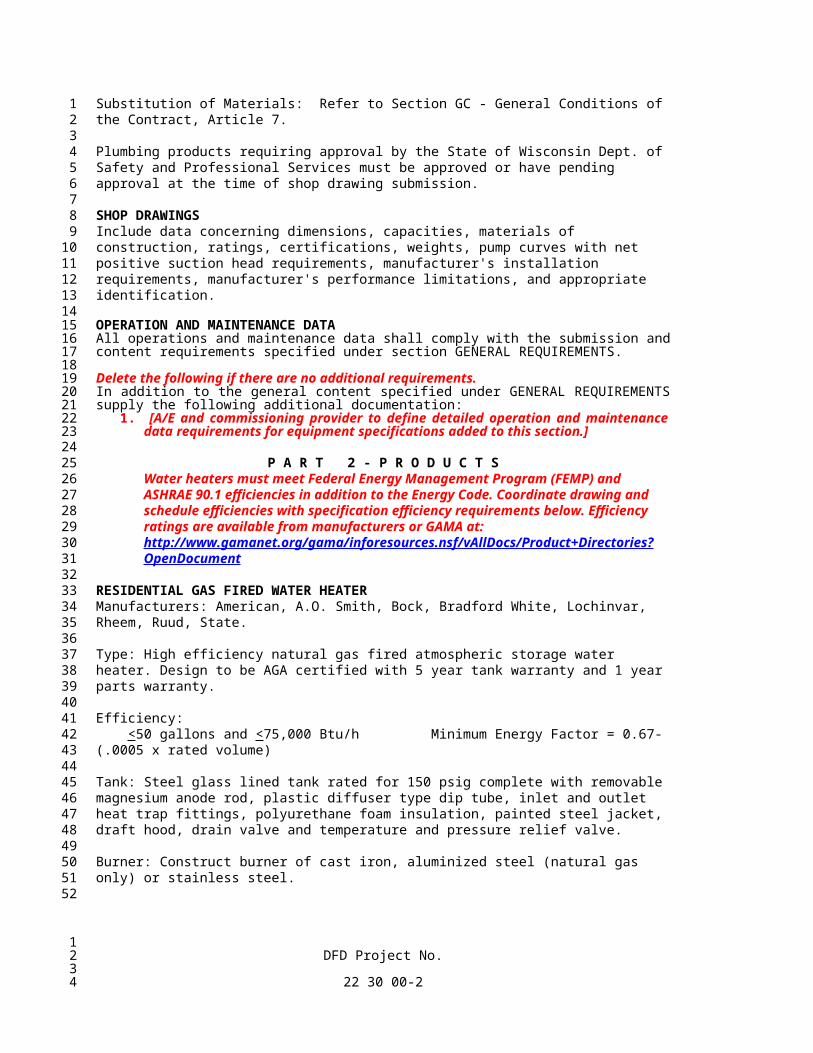
QUALITY ASSURANCESubstitution of Materials: Refer to Section GC - General Conditions of the Contract, Article 7.
Plumbing products requiring approval by the State of Wisconsin Dept. of Safety and Professional Services must be approved or have pending approval at the time of shop drawing submission.
SHOP DRAWINGSInclude data concerning dimensions, capacities, materials of construction, ratings, certifications, weights, pump curves with net positive suction head requirements, manufacturer's installation requirements, manufacturer's performance limitations, and appropriate identification.
OPERATION AND MAINTENANCE DATAAll operations and maintenance data shall comply with the submission and content requirements specified under section GENERAL REQUIREMENTS.Delete the following if there are no additional requirements.In addition to the general content specified under GENERAL REQUIREMENTS supply the following additional documentation:
1. [A/E and commissioning provider to define detailed operation and maintenance data requirements for equipment specifications added to this section.]
P A R T 2 - P R O D U C T SWater heaters must meet Federal Energy Management Program (FEMP) and ASHRAE 90.1 efficiencies in addition to the Energy Code. Coordinate drawing and schedule efficiencies with specification efficiency requirements below. Efficiency ratings are available from manufacturers or GAMA at: http://www.gamanet.org/gama/inforesources.nsf/vAllDocs/Product+Directories?OpenDocument
RESIDENTIAL GAS FIRED WATER HEATERManufacturers: American, A.O. Smith, Bock, Bradford White, Lochinvar, Rheem, Ruud, State.
Type: High efficiency natural gas fired atmospheric storage water heater. Design to be AGA certified with 5 year tank warranty and 1 year parts warranty.
Efficiency: <50 gallons and <75,000 Btu/h Minimum Energy Factor = 0.67-(.0005 x rated volume) Tank: Steel glass lined tank rated for 150 psig complete with removable magnesium anode rod, plastic diffuser type dip tube, inlet and outlet heat trap fittings, polyurethane foam insulation, painted steel jacket, draft hood, drain valve and temperature and pressure relief valve.
Burner: Construct burner of cast iron, aluminized steel (natural gas only) or stainless steel.
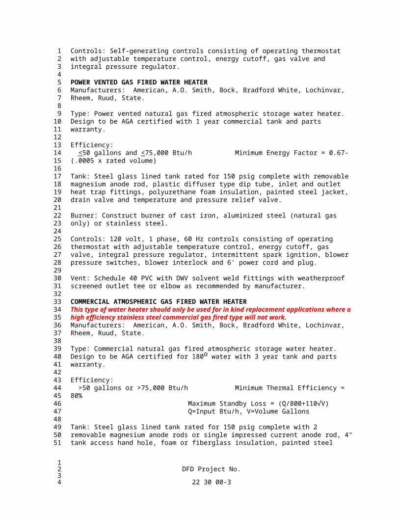
Controls: Self-generating controls consisting of operating thermostat with adjustable temperature control, energy cutoff, gas valve and integral pressure regulator.
POWER VENTED GAS FIRED WATER HEATERManufacturers: American, A.O. Smith, Bock, Bradford White, Lochinvar, Rheem, Ruud, State.
Type: Power vented natural gas fired atmospheric storage water heater. Design to be AGA certified with 1 year commercial tank and parts warranty.
Efficiency: <50 gallons and <75,000 Btu/h Minimum Energy Factor = 0.67-(.0005 x rated volume)
Tank: Steel glass lined tank rated for 150 psig complete with removable magnesium anode rod, plastic diffuser type dip tube, inlet and outlet heat trap fittings, polyurethane foam insulation, painted steel jacket, drain valve and temperature and pressure relief valve.
Burner: Construct burner of cast iron, aluminized steel (natural gas only) or stainless steel.
Controls: 120 volt, 1 phase, 60 Hz controls consisting of operating thermostat with adjustable temperature control, energy cutoff, gas valve, integral pressure regulator, intermittent spark ignition, blower pressure switches, blower interlock and 6' power cord and plug.
Vent: Schedule 40 PVC with DWV solvent weld fittings with weatherproof screened outlet tee or elbow as recommended by manufacturer.
COMMERCIAL ATMOSPHERIC GAS FIRED WATER HEATERThis type of water heater should only be used for in kind replacement applications where a high efficiency stainless steel commercial gas fired type will not work. Manufacturers: American, A.O. Smith, Bock, Bradford White, Lochinvar, Rheem, Ruud, State.
Type: Commercial natural gas fired atmospheric storage water heater. Design to be AGA certified for 180o water with 3 year tank and parts warranty.
Maximum Standby Loss = (Q/800+110√V)Q=Input Btu/h, V=Volume Gallons
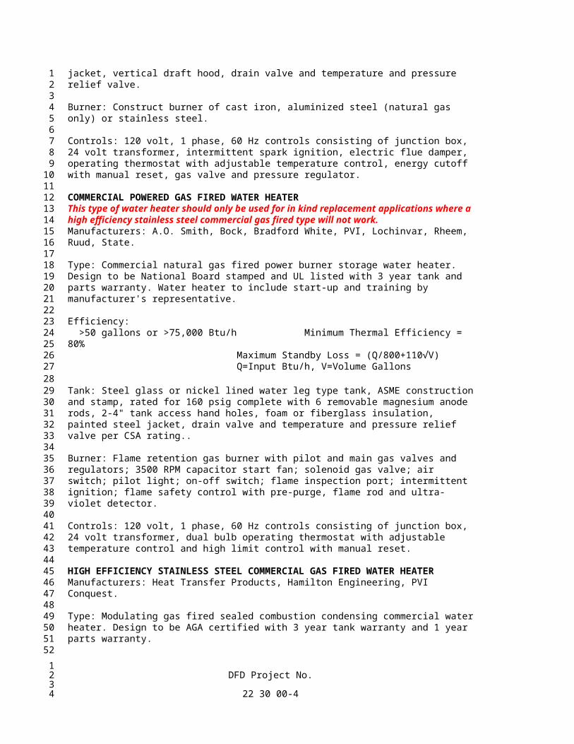
Tank: Steel glass lined tank rated for 150 psig complete with 2 removable magnesium anode rods or single impressed current anode rod, 4" tank access hand hole, foam or fiberglass insulation, painted steel jacket, vertical draft hood, drain valve and temperature and pressure relief valve.
Burner: Construct burner of cast iron, aluminized steel (natural gas only) or stainless steel.
Controls: 120 volt, 1 phase, 60 Hz controls consisting of junction box, 24 volt transformer, intermittent spark ignition, electric flue damper, operating thermostat with adjustable temperature control, energy cutoff with manual reset, gas valve and pressure regulator.
COMMERCIAL POWERED GAS FIRED WATER HEATERThis type of water heater should only be used for in kind replacement applications where a high efficiency stainless steel commercial gas fired type will not work. Manufacturers: A.O. Smith, Bock, Bradford White, PVI, Lochinvar, Rheem, Ruud, State.
Type: Commercial natural gas fired power burner storage water heater. Design to be National Board stamped and UL listed with 3 year tank and parts warranty. Water heater to include start-up and training by manufacturer's representative.
Tank: Steel glass or nickel lined water leg type tank, ASME construction and stamp, rated for 160 psig complete with 6 removable magnesium anode rods, 2-4" tank access hand holes, foam or fiberglass insulation, painted steel jacket, drain valve and temperature and pressure relief valve per CSA rating..
Burner: Flame retention gas burner with pilot and main gas valves and regulators; 3500 RPM capacitor start fan; solenoid gas valve; air switch; pilot light; on-off switch; flame inspection port; intermittent ignition; flame safety control with pre-purge, flame rod and ultra-violet detector.
Controls: 120 volt, 1 phase, 60 Hz controls consisting of junction box, 24 volt transformer, dual bulb operating thermostat with adjustable temperature control and high limit control with manual reset.
HIGH EFFICIENCY STAINLESS STEEL COMMERCIAL GAS FIRED WATER HEATERManufacturers: Heat Transfer Products, Hamilton Engineering, PVI Conquest.
Type: Modulating gas fired sealed combustion condensing commercial water heater. Design to be AGA certified with 3 year tank warranty and 1 year parts warranty.
Efficiency: Minimum Thermal Efficiency = 94%or
Minimum Thermal Efficiency = 93% and Maximum Standby Loss (btu/hr) = .84 x (Q/800+110√V)Q=Input Btu/h, V=Volume Gallons
Tank: 316L stainless steel or phase-balanced austenitic and ferritic duplex steel with minimum 21% chromium mill certified per ASTM A 923 Method A rated for 150 psig complete with stainless steel pipe fittings, submerged combustion chamber, 90/10 cupronickel or 316L stainless steel heat exchanger, insulation, plastic jacket, brass drain valve and temperature and pressure relief valve.
Burner: Side mounted stainless steel power burner.
Controls: 120 volt, 1 phase, 60 Hz self-diagnostic electronic microprocessor controls, intermittent spark or hot surface ignition, operating thermostat with 70o-180oF adjustable temperature control, Energy cutoff with manual reset, blower pressure switch, gas valve and pressure regulator.
Vent: Schedule 40 solid wall CPVC with DWV fittings for flue gas outlet and schedule 40 solid wall PVC with DWV fittings for combustion air intake with solvent weld fittings and vent termination fitting.
Condensate Drain: PVC with solvent weld fittings. Drain neutralizer package.
HIGH EFFICIENCY STAINLESS STEEL DOMESTIC HOT WATER SUPPLY BOILERManufacturers: Heat Transfer Products, Lochinvar, NY Thermal Inc., Triangle Tube.
Type: Gas fired sealed combustion condensing commercial boiler, minimum 93% thermal efficiency and minimum 5 to 1 turn down modulation capability. All components that are in contact with system potable water shall be lead free per the Safe Drinking Water Act, section 1417. The boiler/water heater shall be certified to the ANSI Z21.13/CSA 4.9 gas fired boiler standard and ANSI Z21.10.3/CSA 4.3 gas water heater standard, and be AGA certified. The boiler shall operate in an open loop pressurized system and be directly connected to an external hot water storage tank. A properly sized and manufacturer approved circulating pump is to be included for each unit. Circulating pumps shall comply with pump specifications included elsewhere in this specification section.
Heat Exchanger: The heat exchanger shall be type 316L stainless steel rated for 145 psi operating pressure complete with 125 psig pressure relief valve. The boiler cabinet shall be 20 gauge steel with factory applied painted finish. The boiler shall bear the ASME ‘H’ stamp. The boiler shall include a thermometer and pressure gauge at the outlet piping.
Burner: The burner shall be constructed of 316L stainless steel with stainless steel cylindrical premix burner with woven stainless steel mesh covering, spark igniter, variable speed blower, with low gas pressure switch, water flow switch, low water cutoff and manual reset high limit temperature switch safeties. The burner shall be capable of field conversion between natural and LP gas.
Power: 120 volt, 1 phase, 60 Hz
Controls: The boiler shall include an integrated digital control system with front mounted display to provide information on the operation of the boiler, to include water temperature, adjustable high limit setpoint, adjustable supply water setpoint, with adjustable temperature differential setpoint, and operating and warning lights. The controls shall provide dry contacts for operating an external circulating pump and have dry contacts for an external alarm.
The boiler operating temperature range shall be from 68 degrees to 190 degrees F with differential temperature ranges from 5 degrees to 30 degrees F.
The digital controls shall be capable of operating/regulating up to 8 boilers interconnected in a master/follower configuration. Boilers shall be modulated and staged on/off to maximum energy efficiency.
Vent and Combustion Air: Schedule 40 solid wall CPVC with DWV fittings for flue gas outlet and schedule 40 solid wall PVC with DWV fittings for combustion air intake with solvent weld fittings and vent termination fitting. Size and equivalent length of the intake and exhaust shall comply with the manufacturer’s recommendations.
Condensate Drain: PVC with solvent weld fittings. Drain neutralizer package.
Warranty; Provide 5 years parts and labor warranty.
RESIDENTIAL ELECTRIC WATER HEATERManufacturers: A.O. Smith, American, Bradford White, Lochinvar, Rheem, Ruud, State.
Type: Electric storage domestic water heater. Design to be UL listed with 3 year commercial use tank warranty and 1 year parts warranty.
Efficiency: <12 kW Minimum Energy Factor = .97- (.00035 x Volume (gal)) >12 kW Standby Loss (%/h) = .3+(27/measured tank volume)
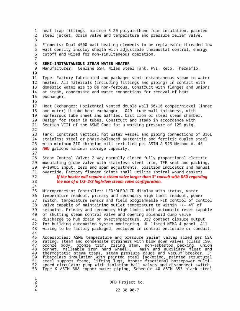
Tank: Steel glass lined tank rated for 150 psig complete with removable magnesium anode rod, plastic diffuser type dip tube, inlet and outlet heat trap fittings, minimum R-20 polyurethane foam insulation, painted steel jacket, drain valve and temperature and pressure relief valve.
Elements: Dual 4500 watt heating elements to be replaceable threaded low watt density incoloy sheath with adjustable thermostat control, energy cutoff and wired for non-simultaneous operation.
Type: Factory fabricated and packaged semi-instantaneous steam to water heater. All materials (including fittings and piping) in contact with domestic water are to be non-ferrous. Construct with flanges and unions at steam, condensate and water connections for removal of heat exchanger.
Heat Exchanger: Horizontal vented double wall 90/10 copper/nickel (inner and outer) U-tube heat exchanger, .049” tube wall thickness, with nonferrous tube sheet and baffles. Cast iron or steel steam chamber. Design for steam in tubes. Construct and stamp in accordance with Section VIII of the ASME Code for a working pressure of 125 psig.
Tank: Construct vertical hot water vessel and piping connections of 316L stainless steel or phase-balanced austenitic and ferritic duplex steel with minimum 21% chromium mill certified per ASTM A 923 Method A. 45 (60) gallons minimum storage capacity.
Steam Control Valve: 2-way normally closed fully proportional electric modulating globe valve with stainless steel trim, TFE seat and packing, 0-10VDC input, zero and span adjustments, position indicator and manual override. Factory flanged joints shall utilize spriral wound gaskets.
If the heater will require a steam valve larger than 3” consult with DFD regarding the use of a 1/3- 2/3 high/low steam valve configuration.
Microprocessor Controller: LED/OLED/LCD display with status, water temperature readout, primary and secondary high limit readout, power switch, temperature sensor and field programmable PID control of control valve capable of maintaining outlet temperature to within +/- 4oF of setpoint. Primary and secondary high limits with automatic reset capable of shutting steam control valve and opening solenoid dump valve discharge to hub drain on overtemperature. Dry contact closure output for building automation system monitoring. UL listed NEMA 4 panel. All wiring to be factory packaged, enclosed in control enclosure or conduit.
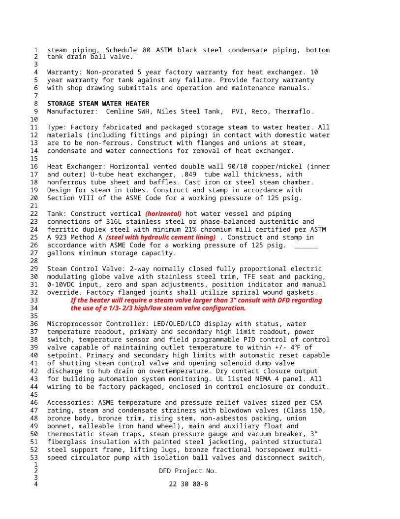
Accessories: ASME temperature and pressure relief valves sized per CSA rating, steam and condensate strainers with blow down valves (Class 150, bronze body, bronze trim, rising stem, non-asbestos packing, union bonnet, malleable iron hand wheel), main and auxiliary float and thermostatic steam traps, steam pressure gauge and vacuum breaker, 3" fiberglass insulation with painted steel jacketing, painted structural steel support frame, lifting lugs, bronze fractional horsepower multi-speed circulator pump with isolation ball valves and disconnect switch, Type K ASTM B88 copper water piping, Schedule 40 ASTM A53 black steel steam piping, Schedule 80 ASTM black steel condensate piping, bottom tank drain ball valve.
Warranty: Non-prorated 5 year factory warranty for heat exchanger. 10 year warranty for tank against any failure. Provide factory warranty with shop drawing submittals and operation and maintenance manuals.
Type: Factory fabricated and packaged storage steam to water heater. All materials (including fittings and piping) in contact with domestic water are to be non-ferrous. Construct with flanges and unions at steam, condensate and water connections for removal of heat exchanger.
Heat Exchanger: Horizontal vented double wall 90/10 copper/nickel (inner and outer) U-tube heat exchanger, .049” tube wall thickness, with nonferrous tube sheet and baffles. Cast iron or steel steam chamber. Design for steam in tubes. Construct and stamp in accordance with Section VIII of the ASME Code for a working pressure of 125 psig.
Tank: Construct vertical (horizontal) hot water vessel and piping connections of 316L stainless steel or phase-balanced austenitic and ferritic duplex steel with minimum 21% chromium mill certified per ASTM
A 923 Method A (steel with hydraulic cement lining) . Construct and stamp in accordance with ASME Code for a working pressure of 125 psig. ______ gallons minimum storage capacity.
Steam Control Valve: 2-way normally closed fully proportional electric modulating globe valve with stainless steel trim, TFE seat and packing, 0-10VDC input, zero and span adjustments, position indicator and manual override. Factory flanged joints shall utilize spriral wound gaskets.
If the heater will require a steam valve larger than 3” consult with DFD regarding the use of a 1/3- 2/3 high/low steam valve configuration.
Microprocessor Controller: LED/OLED/LCD display with status, water temperature readout, primary and secondary high limit readout, power switch, temperature sensor and field programmable PID control of control valve capable of maintaining outlet temperature to within +/- 4oF of setpoint. Primary and secondary high limits with automatic reset capable of shutting steam control valve and opening solenoid dump valve discharge to hub drain on overtemperature. Dry contact closure output for building automation system monitoring. UL listed NEMA 4 panel. All wiring to be factory packaged, enclosed in control enclosure or conduit.
Accessories: ASME temperature and pressure relief valves sized per CSA rating, steam and condensate strainers with blowdown valves (Class 150, bronze body, bronze trim, rising stem, non-asbestos packing, union bonnet, malleable iron hand wheel), main and auxiliary float and thermostatic steam traps, steam pressure gauge and vacuum breaker, 3" fiberglass insulation with painted steel jacketing, painted structural steel support frame, lifting lugs, bronze fractional horsepower multi-speed circulator pump with isolation ball valves and disconnect switch, Type K ASTM B88 copper water piping, Schedule 40 ASTM A53 black steel steam piping, Schedule 80 ASTM black steel condensate piping, bottom tank drain ball valve.
Warranty: Non-prorated 5 year factory warranty for heat exchanger. 10 year warranty for tank against any failure. Provide factory warranty with shop drawing submittals and operation and maintenance manuals.
STORAGE TANKSManufacturers: Heat Transfer Products, Lochinvar, Niles Steel Tank, NTI.
119 gallon vertical (horizontal) 316L stainless steel storage tank and fittings rated for 150 psig and complete with minimum R-12.5 insulation, painted steel or polypropylene jacket, ASME T&P relief valve and bottom tank ball drain valve.
Warranty: 10 year warranty for tank against any failure. Provide factory warranty with shop drawing submittals and operation and maintenance manuals.
Tank: Construct vertical (horizontal) hot water vessel and piping connections of 316L stainless steel or phase-balanced austenitic and ferritic duplex steel with minimum 21% chromium mill certified per ASTM A 923 Method A (steel with hydraulic cement lining). Construct and stamp in accordance with ASME Code for a working pressure of 150 psig. ______ gallons minimum storage capacity.
Accessories: ASME temperature and pressure relief valves sized per CSA rating, minimum R-12.5 insulation with painted steel jacketing, painted structural steel support frame, lifting lugs gasketed, 11”x15” inspection manhole, bottom tank drain ball valve.
Warranty: Non-prorated 10 year warranty for tank against any failure. Provide factory warranty with shop drawing submittals and operation and maintenance manuals.
PLATE AND FRAME HEAT EXCHANGERSIf there is a need to change the heat exchanger capacity in the future by adding or deleting plates, then include the future performance information on the schedule.
Manufactures: Alfa Laval, AIS, Armstrong, Bell & Gossett, ITT Standard, Standard Xchange, Wessels.
Vented double wall plate and frame heat exchanger with gasketed heat transfer channel plates mounted on carrying bars and held between a stationary frame plate and a moveable pressure plate. Design pressure of 150 psig at 230 degrees F in each circuit with no pressure in the other circuit. Heat exchangers shall be constructed and stamped in accordance with the latest ASME Pressure Vessel Code Section VIII.
316 stainless steel corrugated channel plates with one piece Nitrile or EPDM gaskets. Gaskets may be glued or non-glued type. Provide relieving grooves on gaskets to prevent cross contamination between fluids. Provide OSHA compliant aluminum splashguard over channel plate rack.
Carbon steel pressure plates with enamel paint or epoxy coating. Plates shall not require additional stiffeners for support. Carbon steel carrying bars with zinc yellow chromate finish or epoxy coated finish.
NPT 316 stainless steel nozzles for connections 2” and smaller. Studded port type pipe to accept ANSI flanges for connections 3” and larger. Factory seal all connections prior to shipment to prevent entrance of foreign material.
Provide heat exchangers with capacities and operating characteristics indicated on drawings.
WATER SOFTENERSSelect smaller water softening systems sized to handle no more than the service flow rate rather than larger tanks with less frequent regeneration or tanks on standby for extended periods of time. Select multiple tanks for systems with wide flow variations. Supply fixture unit tables based on Hunter’s curves are not corrected for water conserving fixtures and their use commonly results in oversizing. SPS 382.40(7) accepts and DFD recommends sizing based on a detailed engineering analysis to avoid oversizing of equipment. Reference Water Quality Association studies (Aquacraft 2001 single family residence, IAPMO/WQA/ASPE 2016 residential study by Univ. of Cincinnati). Idle conditions contribute to microbiologically induced corrosion and associated water quality concerns. Manufacturers: Capital, Culligan, Hellenbrand, Kinetico, Water Right.
Influent Water Analysis: Constituent
Hardness ___mg/l or ___grains/gallonpH ___Iron ___mg/l and ppmManganese ___mg/l and ppmEnter water data obtained from municipal supplier, Water Quality Association of Wisconsin member or sample submitted to testing lab. If pH is <6.5 and copper piping is used, pH correction is required. pH range of 6.5-7.5 is recommended when water softener is used to remove iron. Iron in excess of 2 mg/l or manganese in excess of 1 mg/l typically requires pretreatment.
Product Standards: NSF/ANSI 61 for materials in contact with water.
NSF/ANSI 44 for residential softeners, control valves 1.25” and smaller, and tank structural.
NSF/ANSI 372 for lead content of materials in contact with water.
Fiberglass Ion Exchange Media Tanks: Fiberglass reinforced ion exchange media tank constructed of molded high density polyethylene inner shell reinforced by exterior fiberglass winding and epoxy resin rated for 150 psig at 120oF with 5 year warranty. Complete with slotted or hub and lateral distributor tube in washed quartz bed or bottom plate distributor.Select fiberglass (preferred) or steel tank construction as appropriate for the size and application and delete the option not used.
Steel Ion Exchange Media Tanks: Welded carbon or stainless steel pressure vessel in accordance with ASME code, 100 PSI working pressure, 120oF, ASME certified and labeled. Provide structural steel leg supports, 4” x 6” top and side hand holes for tanks 30” and smaller and 12”x16” top hand hole and 6”x 8” side hand hole for larger tanks. Blast carbon steel tank exterior to SSPC-SP10 or NACE No. 2, near white metal with 2 mil minimum anchor pattern profile and apply one coat epoxy (Tnemec Series N69F-11SF, Safety Blue), for 4-8 mil minimum dry film thickness. Line carbon steel tank with cross linked epoxy (Devoe Bar-Rust 233H). Abrasive blast interior to SSPC-SP5 or NACE No.1 white metal surface with 2.5 mil anchor pattern profile. Remove all grit, dust, oil and residue. Prime coat and top coat, or single coat for 10-16 mil minimum dry film thickness and force cure.
Ion Exchange Media: High capacity cation ion exchange media, minimum of 8% crosslinked media.
Brine Tank: High density polyethylene salt and brine storage tank with cover, brine well, safety brine valve assembly, air check and overflow fitting. Contractor to provide initial fill with high purity solar or pellet salt recommended by manufacturer.
Control Valve: Top or side-mount glass filled polymer (NorylTM), stainless steel or brass construction with hydraulically balanced piston, seals and spacer. Fully adjustable regeneration cycle durations for backwash, brining/slow rinse, fast rinse, timed brine refill and return to service.
Side-mount multiport electro-coated cast iron diaphragm valve or multiple Y-type electro-coated cast iron or glass filled polymer piston or diaphragm valves with Buna-N diaphragms and ethylene/propylene seals, rated for 100 psig and 120oF. Self-contained pressure compensating flow limiting valves; bronze, stainless steel or PVC construction, rated for 100 psig and 120oF.
Equip twin alternating, demand recall and parallel systems with no hard water bypass to prevent hard water distribution during regeneration.
Microprocessor Controller: LED/OLED/LCD display with status for online, regeneration and standby modes; time of day; gallons since last regeneration and gallons remaining; days until regeneration, flow rate and total volume used. Permanent memory backup of programing and battery backup for time of day. Regeneration programming options include variable reserve, fixed reserve, immediate and delayed regeneration, calendar day override, hardness sensor initiated and pressure differential regeneration.
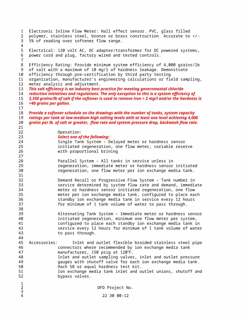
Electronic Inline Flow Meter: Hall effect sensor. PVC, glass filled polymer, stainless steel, bronze or brass construction. Accurate to +/- 5% of reading over softener flow range.
Electrical: 120 volt AC, DC adapter/transformer for DC powered systems, power cord and plug, factory wired and tested controls.
Efficiency Rating: Provide minimum system efficiency of 4,000 grains/lb of salt with a maximum of 10 mg/l of hardness leakage. Demonstrate efficiency through pre-certification by third party testing organization, manufacturer’s engineering calculations or field sampling, meter analysis and adjustment.
This salt efficiency is an industry best practice for meeting governmental chloride reduction initiatives and regulations. The only exception to this is a system efficiency of 3,350 grains/lb of salt if the softener is used to remove iron > 2 mg/l and/or the hardness is >40 grains per gallon.
Provide a softener schedule on the drawings with the number of tanks, system capacity ratings per tank at low-medium-high salting levels with at least one level achieving 4,000 grains per lb. of salt or greater, flow rate and system pressure drop, backwash flow rate.
Operation:Select one of the following:Single Tank System – Delayed meter or hardness sensor initiated regeneration, one flow meter, variable reserve with proportional brining
Parallel System – All tanks in service unless in regeneration, immediate meter or hardness sensor initiated regeneration, one flow meter per ion exchange media tank.
Demand Recall or Progressive Flow System – Tank number in service determined by system flow rate and demand, immediate meter or hardness sensor initiated regeneration, one flow meter per ion exchange media tank, configured to place each standby ion exchange media tank in service every 12 hours for minimum of 1 tank volume of water to pass through.
Alternating Tank System – Immediate meter or hardness sensor initiated regeneration, minimum one flow meter per system, configured to place each standby ion exchange media tank in service every 12 hours for minimum of 1 tank volume of water to pass through.
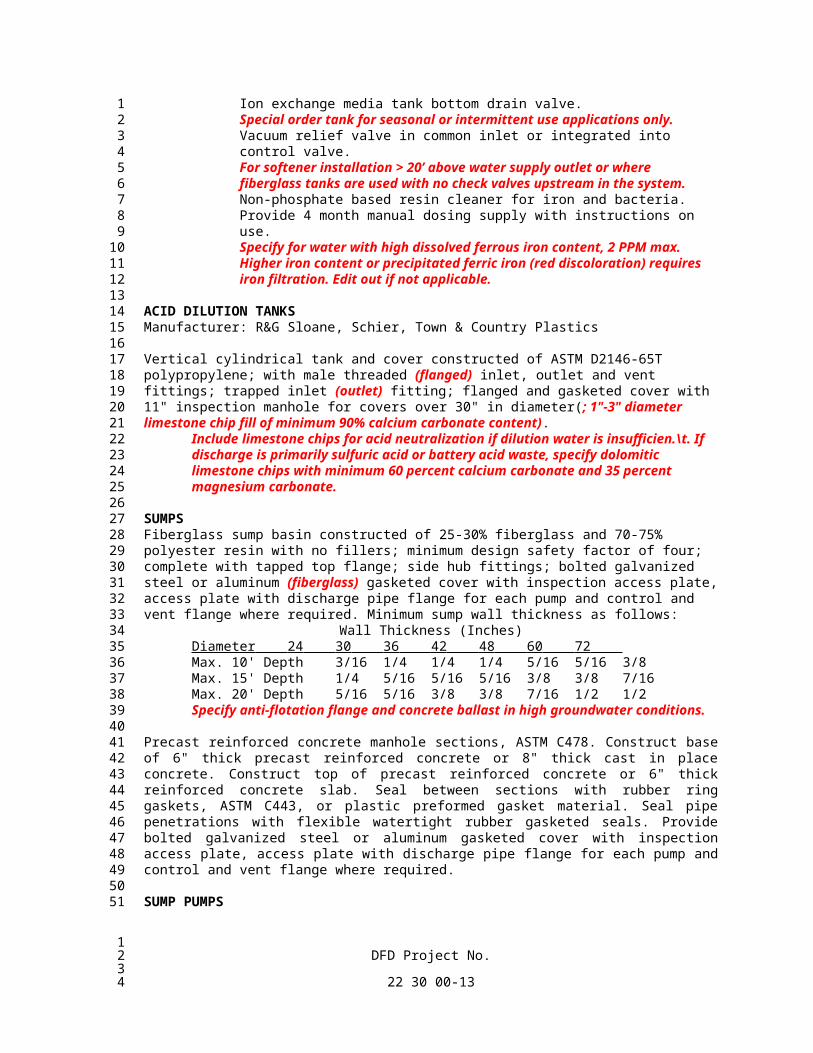
Accessories: Inlet and outlet flexible braided stainless steel pipe connectors where recommended by ion exchange media tank manufacturer, 150 psig at 120oF.Inlet and outlet sampling valves, inlet and outlet pressure gauges with shutoff valve for each ion exchange media tank.Hach 5B or equal hardness test kit.Ion exchange media tank inlet and outlet unions, shutoff and bypass valves.Ion exchange media tank bottom drain valve.Special order tank for seasonal or intermittent use applications only.Vacuum relief valve in common inlet or integrated into control valve.For softener installation > 20’ above water supply outlet or where fiberglass tanks are used with no check valves upstream in the system. Non-phosphate based resin cleaner for iron and bacteria. Provide 4 month manual dosing supply with instructions on use. Specify for water with high dissolved ferrous iron content, 2 PPM max. Higher iron content or precipitated ferric iron (red discoloration) requires iron filtration. Edit out if not applicable.
ACID DILUTION TANKSManufacturer: R&G Sloane, Schier, Town & Country Plastics
Vertical cylindrical tank and cover constructed of ASTM D2146-65T polypropylene; with male threaded (flanged) inlet, outlet and vent fittings; trapped inlet (outlet) fitting; flanged and gasketed cover with 11" inspection manhole for covers over 30" in diameter(; 1"-3" diameter limestone chip fill of minimum 90% calcium carbonate content).
Include limestone chips for acid neutralization if dilution water is insufficien.\t. If discharge is primarily sulfuric acid or battery acid waste, specify dolomitic limestone chips with minimum 60 percent calcium carbonate and 35 percent magnesium carbonate.
SUMPSFiberglass sump basin constructed of 25-30% fiberglass and 70-75% polyester resin with no fillers; minimum design safety factor of four; complete with tapped top flange; side hub fittings; bolted galvanized steel or aluminum (fiberglass) gasketed cover with inspection access plate, access plate with discharge pipe flange for each pump and control and vent flange where required. Minimum sump wall thickness as follows:
Precast reinforced concrete manhole sections, ASTM C478. Construct base of 6" thick precast reinforced concrete or 8" thick cast in place concrete. Construct top of precast reinforced concrete or 6" thick reinforced concrete slab. Seal between sections with rubber ring gaskets, ASTM C443, or plastic preformed gasket material. Seal pipe penetrations with flexible watertight rubber gasketed seals. Provide bolted galvanized steel or aluminum gasketed cover with inspection access plate, access plate with discharge pipe flange for each pump and control and vent flange where required.
Type: Submersible pumps constructed of epoxy coated cast iron shell, cast iron volute, two vane enclosed (semi-open, or recessed vortex) non-clog cast iron, bronze or thermoplastic impeller, stainless steel shaft, stainless steel fasteners, upper and lower ball bearings, oil lubricated or factory sealed grease lubricated, and ceramic mechanical seal.
Motor: Hermetically sealed, capacitor start, with built-in thermal overload protection sized for non-overloading over the entire pump curve.
CONTROLS: Single On/Off float switch, UL listed. Double (one On, one Off) float switch, UL listed. Triple (1st pump On, 2nd pump on, both pumps Off) float switch, UL listed. Four (1st pump On, 2nd pump on, both pumps Off, high level alarm) float switches, UL listed. NEMA 1 indoor alarm panel with warning light, horn, silence switch, test switch and high level
alarm switch, UL listed. NEMA 4X outdoor alarm panel with warning light, horn, silence switch, test switch and high level
alarm switch, UL listed. Combination magnetic starter with fused disconnect switch, HOA switch, run light, resettable
overload heaters, NEMA 1 (NEMA 4), UL listed. Mechanical pump alternator with mechanical switch and float mechanism for control of 1st pump
On, 2nd pump On, both pumps Off and alarm, with alarm panel, warning light, horn, silence switch, test switch, NEMA 1. (NEMA 4)
Electrical pump alternator and alarm panel with combination magnetic starter for each pump, fused disconnect switch, external HOA switch for each pump, run light for each pump, resettable
overload heaters, warning light, horn, silence switch, test switch, labeled terminal switch and devices, auxiliary dry contact for remote alarm, UL listed components, NEMA 1 (NEMA 4).
ACCESSORIES: 10’ power cord. 20’ power cord. NEMA 4 junction box. Discharge check valve, fullport ball valve and union for each pump. Dual mechanical seals, seal leak detector probe and warning light in control
panel. Dual stainless steel lift out guide rails with stainless steel wall, pump and
sump brackets, bronze and neoprene quick disconnect fitting and corrosion proof pull chain or cable.
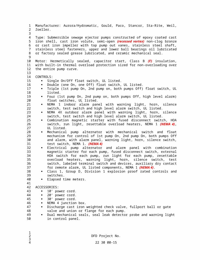
Type: Submersible sewage ejector pumps constructed of epoxy coated cast iron shell, cast iron volute, semi-open (recessed vortex) non-clog bronze or cast iron impeller with top pump out vanes, stainless steel shaft, stainless steel fasteners, upper and lower ball bearings oil lubricated or factory sealed grease lubricated, and ceramic mechanical seal.
Motor: Hermetically sealed, capacitor start, Class B (F) insulation, with built-in thermal overload protection sized for non-overloading over the entire pump curve.
CONTROLS: Single On/Off float switch, UL listed. Double (one On, one Off) float switch, UL listed. Triple (1st pump On, 2nd pump on, both pumps Off) float switch, UL listed. Four (1st pump On, 2nd pump on, both pumps Off, high level alarm) float switches, UL listed. NEMA 1 indoor alarm panel with warning light, horn, silence switch, test switch and high level
alarm switch, UL listed. NEMA 4X outdoor alarm panel with warning light, horn, silence switch, test switch and high level
alarm switch, UL listed. Combination magnetic starter with fused disconnect switch, HOA switch, run light, resettable
overload heaters, NEMA 1 (NEMA 4), UL listed. Mechanical pump alternator with mechanical switch and float mechanism for control of 1st pump
On, 2nd pump On, both pumps Off and alarm, with alarm panel, warning light, horn, silence switch, test switch, NEMA 1. (NEMA 4)
Electrical pump alternator and alarm panel with combination magnetic starter for each pump, fused disconnect switch, external HOA switch for each pump, run light for each pump, resettable overload heaters, warning light, horn, silence switch, test switch, labeled terminal switch and devices, auxiliary dry contact for remote alarm, UL listed components, NEMA 1 (NEMA 4).
Class 1, Group D, Division 1 explosion proof rated controls and switches. Elapsed time meters.
ACCESSORIES: 10’ power cord. 20’ power cord. 30’ power cord. NEMA 4 junction box.
Discharge cast iron weighted check valve, fullport ball or gate valve and union or flange for each pump.
Dual mechanical seals, seal leak detector probe and warning light in control panel.
Dual stainless steel lift out guide rails with stainless steel or cast iron wall, pump and sump brackets, bronze and neoprene quick disconnect fitting and corrosion proof pull chain or cable.
Explosion proof Class 1, Group D, Division 1 motor.
IN-LINE CENTRIFUGAL PUMPSManufacturer: Bell and Gossett, Gould, Grundfos, Taco.
Type: Horizontal single stage oil lubricated in-line pumps, 125 psig maximum working pressure at operating temperature of 225oF continuous. The manufacturer shall certify all pump ratings. All pumps to operate without excessive noise or vibration.
Casing: Bronze or stainless steel; flanged suction and discharge connection.
Impeller: Brass or bronze, keyed to the shaft, single suction enclosed type, hydraulically and dynamically balanced.
Bearings: Oil lubricated bronze sleeve or ball bearings.
Shaft: Stainless steel or carbon steel with stainless steel or bronze sleeve, integral thrust collar.
Seal: Mechanical type, carbon rotating against a stationary ceramic seat, 225°F maximum continuous operating temperature.
Drive: Flexible coupling.
Motor: Provide pump with open dripproof motor with built-in thermal overload protection sized for non-overloading over the entire pump curve. Furnish each pump and motor with a nameplate giving the manufacturer's name, serial number of pump, capacity in GPM and head in feet at design condition, horsepower, voltage, frequency, speed and full load current.
IN-LINE CLOSE COUPLED CENTRIFUGAL PUMPSManufacturer: Bell and Gossett, Gould, Grundfos, Taco.
Type: Horizontal single stage close coupled oil lubricated in-line pumps, 125 psig maximum working pressure at operating temperature of 225oF continuous. The manufacturer shall certify all pump ratings. All pumps to operate without excessive noise or vibration.
Casing: Bronze or stainless steel; flanged suction and discharge connection.
Impeller: Brass, bronze or thermoplastic, keyed to the shaft, single suction enclosed type, hydraulically and dynamically balanced.
Bearings: Oil lubricated bronze sleeve or ball bearings.
Shaft: Stainless steel or carbon steel with stainless steel or bronze sleeve, integral thrust collar.
Seal: Mechanical type, carbon rotating against a stationary ceramic seat, 225°F maximum continuous operating temperature.
Motor: Provide pump with open dripproof motor with built-in thermal overload protection sized for non-overloading over the entire pump curve. Furnish each pump and motor with a nameplate giving the manufacturer's name, serial number of pump, capacity in GPM and head in feet at design condition, horsepower, voltage, frequency, speed and full load current.
IN-LINE SYSTEM LUBRICATED CENTRIFUGAL PUMPSManufacturer: Bell and Gossett, Grundfos, Taco.
Type: Horizontal single stage close coupled system lubricated in-line pumps, 125 psig maximum working pressure at operating temperature of 225oF continuous. The manufacturer shall certify all pump ratings. All pumps to operate without excessive noise or vibration.
Casing: Bronze or stainless steel; flanged suction and discharge connection.
Impeller: Bronze, stainless steel or thermoplastic, keyed to the shaft, single suction enclosed type, hydraulically and dynamically balanced.
Bearings: System lubricated carbon sleeve bearings.
Shaft: Stainless steel or ceramic.
Seal: Stainless steel can isolating rotor and stator.
Motor: Provide pump with impedance protected motor sized for non-overloading over the entire pump curve. Furnish each pump and motor with a nameplate giving the manufacturer's name, serial number of pump, capacity in GPM and head in feet at design condition, horsepower, voltage, frequency, speed and full load current.
DOMESTIC WATER VARIABLE SPEED BOOSTER PUMPSManufacturer: Aurora, Bell and Gossett, SyncroFlo, Taco, Tigerflow, Grundfos.
General: Factory packaged and tested duplex (triplex) domestic water booster pumps with all components fully frame mounted, piped, painted, wired and tested at factory. Entire booster pump skid to carry ANSI/NSF 61 certification for drinking water.
Type: High efficiency vertical (horizontal) multi-stage (close-coupled end suction) pumps, 150 (300) psig maximum working pressure at operating temperature of 225oF. continuous. The manufacturer shall certify all pump ratings. All pumps to operate without excessive noise or vibration.
Casings: Top or rear pullout design with 304 or 316 stainless steel or gray iron volute, backplate and stainless steel or bronze wearing rings.
Impellers: 304 or 316 stainless steel, lead free brass or bronze, keyed to the shaft, hydraulically and dynamically balanced.
Shafts: Stainless or carbon steel with stainless steel or bronze sleeve, integral thrust collar.
Seals: Mechanical type, carbon rotating against a stationary ceramic seat, 225°F maximum continuous operating temperature.
Motors: Provide pumps with open dripproof motor sized for non-overloading over the entire pump curve. Furnish each pump and motor with a nameplate giving the manufacturer's name, serial number of pump, capacity in GPM and head in feet at design condition, horsepower, voltage, frequency, speed and full load current.
Valves: Lead free butterfly or ball isolation valves at inlet and outlet of each pump and non-slam silent check valves at discharge of each pump. Pump casing discharge temperature relief valves piped to floor/hub drain.
Pressure Gauges: One per pump piped with isolation valves to pump suction and discharge.
Manifold Piping: 304 or 316 stainless steel rated for 300 psig, sized for maximum velocity of 10 ft/s.
Variable Frequency Drives (VFD’s): The unit shall be U.L. listed, solid state, microprocessor based with a pulse width modulated (PWM) output wave form (none others are acceptable).
The VFD shall employ a full wave bridge rectifier and capacitors to minimize the ripple of the rectified voltage to maintain near constant DC voltage. Insulated gate bipolar transistors (IGBT’s) shall be employed as the output switching device.
The VFD package shall contain the equivalent of 5% impedance to reduce harmonic distortion. The 5% equivalent impedance shall be provided in the form of a DC bus choke, an input AC line reactor in each phase, or a combination of the two methods.
Control circuitry shall be plug-in, plug-out modular basis with a corrosion resistant coating on printed circuit boards.
Units to be suitable for an operating environment from 0°C to 40°C temperature and humidity up to 90% non-condensing.
Units shall be suitable for input power of electrical system as scheduled on the drawings ±10%, 3 phase, 60 Hertz nominal.
Use a current limiting control device to limit output current to 110% continuous for one minute; also refer to Protection Features in this section. Full load output current available from drive shall not be less than motor nameplate amperage. The full load amp rating of the VFD shall not be less than the values indicated in the NEC Table 430-150.
Output power shall be suitable for driving standard NEMA B design, three phase alternating current induction motors at full rated speed with capability of 6:1 turndown.
Controls: Electronic programmable logic controller with non-volatile memory (no battery backup required), LED/OLED/LCD display of setpoints, pump status, speed, manual speed setting, flow rate GPM, suction and discharge pressure, low and high pressures, pump(s) currently running, pump run time, visual and audible alarms and event history. Controller to include virtual H-O-A switch for each pump and manual speed control, low and high pressure settings with adjustable on/off delays and manual-auto option reset, automatic and manual pump alternation, minimum pump runtimes, alarm silence. PID control algorithm
capable of meeting ASHRAE 90.1 requirements. Equip with 4-20 mA suction and discharge (and remote) pressure transducers. Provide VFD’s as specified above for modulating the speed of each pump. Enclose in UL NEMA 1 control panel with the following components: VFD’s, magnetic across the line motor starters with 3 leg overload protection and external resets, starter failure interlocks, single door interlocked disconnect with individual fuses, control circuit transformer with protected secondary.
The use of a compression tank with minimum 30 gallon acceptance volume is recommended to carry building through periods of small demand without inefficient excessive pump cycling. The compression tank should be located at the top of the building to minimize tank air volume and size.
EXPANSION TANKSManufacturer: Amtrol, Bell and Gossett, Wessels.
Vertical steel precharged hydro-pneumatic expansion tank, 125 psi ASME labeled construction, complete with replaceable flexible butyl rubber bladder, system connection fitting, Schrader type air charge fitting, steel base ring stand, factory prime and enamel painted exterior finish, ASME relief valve. Materials exposed to water to be NSF or FDA approved for potable water service.
P A R T 3 - E X E C U T I O N
INSTALLATIONInstall plumbing equipment where indicated in accordance with manufacturer's recommendations. Coordinate equipment location with piping, ductwork, conduit and equipment of other trades to allow sufficient clearances. Locate equipment and arrange plumbing piping to provide access space for servicing all components.
Set commercial water heaters, commercial water softeners, storage tanks and booster pumps on concrete housekeeping pads. Adjust and level equipment.
Set sumps on compacted granular backfill adjusting for plumb and level. Backfill in even layers around sump with granular backfill.
Connect equipment to water and drain piping using unions or flanges and isolation valves. Water softener drain pipe and fittings to be solvent welded PVC/CPVC SDR 13.5. Water softener brine piping to be polyethylene as supplied by softener manufacturer or same as drain piping.Confirm water softener hub/floor drain size is sized to accept maximum backwash flowrate.
Connect pneumatic controls to compressed air source.
Size temperature and relief valves per CSA ratings. Pipe temperature and pressure relief valves to floor drain or floor as indicated.
Startup and test equipment adjusting operating and safety controls for proper operation.
Water Softener Startup: Do not fill water softeners with water or startup until building occupancy and active use to avoid stagnant conditions and resulting microbiological contamination. Maintain water softeners in dry bypass mode until active use. Program and cycle water softeners for specified minimum efficiency rating, regeneration cycle intervals and times, consumption, backflow rate, brine flow rate, variable reserve and proportional brining, etc. Program standby ion exchange media tanks into service every 12 hours for minimum of 1 tank full of water to pass through. Provide initial salt fill of brine tank. Test and report on untreated and treated water hardness, pH, iron and chlorine. For water softeners
demonstrating efficiency through field sampling, meter analysis and adjustment; report field data confirming efficiency.
Lubricate pumps before startup. Adjust pumps for rated flow. Clean and blowdown strainers after 8 hours of operation.
Adjust compression tank precharge to scheduled minimum operating pressure prior to connecting to system.
CONSTRUCTION VERIFICATION ITEMSContractor is responsible for utilizing the construction verification checklists supplied under specification Section 22 08 00 in accordance with the procedures defined for construction verification in Section 01 91 01 or 01 91 02.
FUNCTIONAL PERFORMANCE TESTINGContractor is responsible for utilizing the functional performance test forms supplied under specification Section 22 08 00 in accordance with the procedures defined for functional performance testing in Section 01 91 01 or 01 91 02.
AGENCY TRAININGAll training provided for agency shall comply with the format, general content requirements and submission guidelines specified under Section 01 91 01 or 01 91 02.