144
Product Catalogue Flexible Conduit Systems, Glands, Rigid Conduit Fittings and Accessories for Hazardous and Hostile Areas A Member of the ABB Group

Flexible C
on
du
it Systems, G
land
s, Rig
id C
on
du
it Fitting
s & A
ccessories fo
r Hazard
ou
s and
Ho
stile Areas
Product CatalogueFlexible Conduit Systems, Glands,
Rigid Conduit Fittings and Accessories for Hazardous and Hostile AreasThe contents of this Thomas & Betts catalogue have been carefully checked for accuracy at the time of print. However,
Thomas & Betts does not provide a catalogue warranty of any kind, express or implied, in this respect and shall not be liable for any loss or damage that may result from any use or as a consequence of any inaccuracies in or any omissions from the information contained within this catalogue.
Copyright Thomas & Betts 2014. Copyright in these pages is owned by Thomas & Betts except where otherwise indicated. No part of this publication may be reproduced, copied or transmitted in any form or by any means, without our prior written permission. Images, trade marks, brands, designs and technology are also protected by other intellectual property rights and may not be reproduced or appropriated in any manner without written permission of their respective owners. Thomas & Betts reserves the right to change and improve any product specifications or other mentions in the catalogue at its own discretion and at any time. These conditions of use are governed by the laws of the Netherlands and the courts of Amsterdam shall have exclusive jurisdiction in any dispute.
Thomas & Betts manufactures and designs a wide range of electrical equipment for hazardous and hostile environments to ensure the safety of the personnel working in them. The extensive range covers Kopex-Ex metallic and non metallic conduit and fittings, Star Teck(r) teck cable fittings and T&B(r) rigid conduit fittings. These products are approved to a wide range of hazardous area standards including ATEX, IECEx, UL, CSA, GOST and Inmetro.
Thomas & Betts Sales Offices
CanadaT +1 450 347 5318 E [email protected]
France / BelgiumT +33 (0) 1 64 40 27 26E [email protected]
Germany / AustriaT +49 (0) 62 21 701-1800 E [email protected]
ItalyT +39 (0) 2 2415 3000
NetherlandsT +31 (0) 180 641 888E [email protected]
SpainT +34 938 45 4570E [email protected]
Switzerland (PMA)T +41 44 905 61 11 E [email protected]
UKT +44 (0) 1675 468 213E [email protected]
LIT-
152G
BR 0
9/14
• D
esig
ned
by w
ww
.uc4
.co.
uk
A Member of the ABB Group A Member of the ABB Group

Welcome toThomas & Betts
Introduction
2
At Thomas & Betts, our focus is on improving your business
performance by providing practical, reliable electrical
products and services. To connect and protect for life. To
solve everyday problems in the areas of Wire and Cable
Management, Cable Protection, Power Connection and
Control and Safety. Our extensive engineering, supply
chain management and technical sales support teams are
committed to understanding everything that impacts
your ability to accomplish your business objectives by
reducing your total cost of ownership.
Whether you are designing, installing, operating, maintaining
or owning an office building, off-shore platform, hospital,
or a high speed train, power generating plant, machine
equipment or a manufacturing facility, Thomas & Betts
engineered products’ fit and function in your application
provide superior performance, sustainability, and value
throughout the project life cycle.
All our brands are built upon four product and service
solution platforms. Platforms that address your or
your customers’ critical electrical and lighting needs
covering the protection of data, energy, processes, assets
and personal safety. Beyond hi-performance application
characteristics, Thomas & Betts products, information and
services facilitate and speed up your time critical assembly,
installation or maintenance processes.

Contents
3
ContentsOil and gas - upstream applications 4-5
Oil and gas - midstream applications 6-7
Oil and gas - downstream applications 8-9
Food and beverage applications 10
Chemical and pharmaceutical applications 11
World standards and what they mean 12-13
Zone definitions - onshore gases and vapours 14-15
Zone definitions - offshore gases and vapours 16
Zone definitions - dust 17
Kopex Ex - product marking guide 18-19
Star Teck® - product marking guide 20-21
Index of ingress protection 22
Photometry 23
Kopex Ex conduit systems 24-25
Selection guide 26-27
EXB / EXBB / XESX range 28-29
EXPQM / EXBQA range 30-31
NENV / NENZ range 32-33
NEBV 90º curved elbow / NEWV 90º elbow / 34-35
NEAV 45º elbow range / BESGR /
BEYR Y piece / BETR T piece range
BEAVR / NEIR / HEAK / BENR-REM / BEH range 36-37
EXLB / EXLT / EXLH / EXBBT / EXLHC range 38-39
EXSB / EXST / EXSH / EXSBBT / EXSHC range 40-41
G1 gland / 90º elbow gland 42-44
Universal / universal swivel gland 45-47
XP flex range 48-49
Kopex Ex cable glands 50-51
Cable glands, thread convertors, stopping plugs
and accessories - selection guide 52-53
Ex d double compression cable gland - C1 series 54-55
Ex e cable gland - C2 series 56-57
Ex d single compression cable gland - C3 series 58-59
Ex d flameproof cable gland - C4 series 60-61
Ex d flameproof cable gland - C5 series 62-63
Nylon cable gland 64-65
www.tnb-hazardous.comA Member of the ABB Group
Star Teck® cable glands 66-67
Selection guide 68-69
Star Teck® ST series - installation and
technical overview 70-71
Star Teck® series - installation and technical overview 72-73
Star Teck® ST series 74-75
Star Teck XP® (STX) series 76-77
Star Teck Extreme® (STE) series 78-79
Star Teck Extreme XP® (STEX) series 80-81
Star Teck Extreme DirectorTM (STED) series 82-83
Bond StarTM grounding locknut 84-85
IBERVILLE® TEKTM cable fittings 86-87
IBERVILLE® TCAXTM explosion-proof cable fittings 88-89
Rigid conduit fittings 90-91
Selection guide 92-93
GUA series - conduit outlet boxes 94-97
GA series - aluminium external hubs 98-101
EXUN series - aluminium internal hubs 102-103
GASS series - aluminium internal hubs 104
GUP series - explosion-proof enclosure 105
LB and T style - aluminium conduit body 106-107
OE series - iron conduit outlet bodies 108-109
Capped elbows - iron and aluminium 110-111
Reducers, plugs and adapters 112-113
UN series - three-piece Unions 114-115
EX series - aluminium three-piece unions 116-117
EYD and ECD series - drain seals and breathers 118-119
EYS series - sealing fittings 120-121
EYVF and EVHF series - sealing fittings 122-123
Sealing cement and fiber 124-125
Thread converters, stopping plugs & accessories 126-127
Enlargers, reducers and thread convertors 128-129
Ex d stopping plugs - standard / tamperproof 130-131
Ex e stopping plugs - hex head / dome head / nylon 132-133
Accessories 134-135
Index 136-141
Thomas & Betts worldwide industrial capabilities 142

4
www.tnb-hazardous.com
Oil and gas - upstream applications
The oil and gas market is split into three sectors Upstream,
Midstream and Downstream. Upstream consists of Exploration
and production. Both these areas offer very distinct and unique
challenges to people and equipment working within them.
Firstly, there are offshore applications such as the drilling rigs
and production platforms. These are always open to extreme
weather conditions so equipment used here needs to be able to
withstand a salty environment. This is achieved through either
manufacturing product from stainless steel, as is the case for
Kopex-Ex conduit glands, or by ensuring that the product is
coated or painted to withstand marine environments.
Equipment in offshore applications also needs to be hardwearing and
easy to maintain as production downtime can be extremely costly.
For example, a FPSO (Floating Production Storage and Offloading)
vessel can produce up to 200,000 barrels of crude oil per day at
approx $80 to $90 per barrel. A breakdown would result in a loss of
revenue of over $700,000 per hour.
Industry overview Approvals / Characteristics
Product selection criteria
• Salt water corrosion (offshore platforms)• Oil and chemical resistance (Drilling rig MUD)• Extreme ambient temperature• Protection level• Connectivity to other pieces of equipment• Consequence of down time• Approval level required (Ex e, Ex d, etc.)• Approval specification required ATEX, IECEx,
UL, GOST, CSA etc.• Where product will be positioned, e.g. Zone 1 or Zone 2

Oil and gas - upstream applications
5
www.tnb-hazardous.com
This has led to Thomas & Betts products being used in many
offshore applications to protect critical data and power cables
across these massive vessels. Whether it is data cables from a
gas detector or the cable protection on a power transmission
unit, Thomas & Betts offers a whole range of products that are
tested and approved to many of the world standards.
Onshore applications can also be split into exploration and
production. Single onshore wells may produce as little as a few
barrels per day but networking of onshore wells can result in
production of milliions of barrels per day.
This brings with it a whole new series of challenges to be
overcome. Firstly, the drilling rigs tend to be mobile with motors
and pumps often mounted on skids for easy transportation. This
can lead to issues of connectivity for which Thomas and Betts has a
range of thread converters in a variety of materials, many meeting
world standards, ready to resolve the problem.
Secondly, so many rigs in network requires a massive monitoring
operation to ensure that the flow of all the rigs is ongoing and
consistent. This makes the protection of data cable critical. With
the broadest range of systems and approvals, Thomas & Betts
leads the field in providing solutions.
A Member of the ABB Group

6
Oil and gas - midstream applications
Midstream relates to the transportation, storage and partial
processing of crude oil and gas from the wellheads to the refining
plants. This brings another set of challenges to overcome.
One challenge relates to what is pumped out of the well. It is not
pure and often contains a mixture of oil, gas, water and often
sand which must be separated before being shipped or piped to
a storage facility.
The separation can be accomplished in a variety of ways
depending on the type of oil or gas that the well is pumping and
can often take up to 4 processes before the commodity is
separated out ready for piping or shipping. These processes
require energy and this energy is often created by the utilization
of the gas in the commodity itself.
In the case of an offshore rig, this separating is often done on shore
away from the rig then pumped to the storage depots. In the case of
the FPSO vessels, it is all done on board and the oil is transferred to
tankers at sea for delivery to storage depots. Once the separating is
complete, the commodity can then be moved to storage.
Industry overview Approvals / Characteristics
Product selection
• Salt water corrosion (tankers)
• Extreme ambient temperature
• Protection level
• Consequence of down time
• Approval level required (Ex e, Ex d, etc.)
• Approval specification required ATEX, IECEx,
UL, GOST, CSA etc
• Where product will be positioned, e.g. Zone 1
or Zone 2
www.tnb-hazardous.com

Oil and gas - midstream applications
7
At this point, metering needs to take place to calculate
invoices and assess taxes. Accuracy is required to not only
measure the amount of oil produced but also the density,
viscosity, pressure and temperature, and in the case of gas, the
amount of water vapour.
Oil is often pumped directly to the oil refinery where the down
stream operation begins, often travelling through a series of
pumps to get the required pressure.
Thomas & Betts offers a range of products and services to meet the
demands of midstream oil and gas markets.
www.tnb-hazardous.comA Member of the ABB Group

8
Oil and gas - downstream applications
The term downstream relates to the processing and delivery of
finished carbon related product to the end-user. This covers a whole
range of applications from refining to petrol stations.
There are over 700 refineries globally all competing to supply
finished carbon based products to local and international markets.
The products refined are varied including:
• Transportation fuels
LPG, gasoline, jet fuel, diesel, gas oil and bunker fuel
• Petrochemical feedstocks
LPG, naphtha and aromatics
• Energy sources
LPG, kerosene, heating oil and fuel oil
• Specialities
Lubricants, bitumen, coke, solvents and waxes
• Petrochemical feedstocks
Synthetic fibres (nylon), plastics (polyethylene, PVC)
Industry overview Approvals / Characteristics
Product Selection
• Continual movement (CCTV)
• Extreme ambient temperature
• Protection level
• Consequence of down time
• Approval level required (Ex e, Ex d, etc.)
• Approval specification required ATEX, IECEx,
CSA etc.
• Where product will be positioned, e.g. Zone 1
or Zone 2
www.tnb-hazardous.com

Oil and gas - downstream applications
9
Refining is a four stage process. It begins with distillation which
separates the commodity into 5 product sectors: LPG, Naphtha,
Kerosene, Gas, Oil, and Atmospheric residue. Distillation is
accomplished using high temperatures. The higher the
temperature, the higher the quality of the end product.
The second stage is upgrading or reforming. This stage is used
to change the product at a molecular level; for example,
changing low octane Naphtha to high octane which can then
be blended into gasoline.
Stages three and four are treatment processes which remove
impurities such as sulphur and blend the refined product into
distinct products for the market.
The final stage of the downstream process is delivery to the
market which involves storage and transportation. For example,
aviation fuel can be shipped direct to airports by road or rail
where it is stored, before being transferred directly to tanker
trunks for refuelling of aircraft.
www.tnb-hazardous.comA Member of the ABB Group

10
Food processing - explosion proof (dust) Beverage manufacture - explosion proof (vapour)
Food industry
Thomas & Betts offers a range of products for the food
processing market, including products for use in areas
where stainless steel is preferred as well as areas classed as
hazardous.
Beverage industry
Thomas & Betts has a range of products designed for use
in all beverage production sectors in the malting,
brewing, wine, spirits or soft drink business.
Food and beverage applications
www.tnb-hazardous.com

Pharmaceutical Applications
11
Chemical engineering - explosion proof Pharmaceutical production - explosion proof
Chemical industry
The chemical industry produces very diverse products,
including everything from fertilizers to explosives such as
nitroglycerin.
Pharmaceutical industry
The Thomas & Betts range of products and solutions are
ideal for use in the pharmaceutical Industry. Whether
it is upstream in the primary production stage or
downstream in the packing stage.
Chemical and pharmaceutical applications
www.tnb-hazardous.comA Member of the ABB Group
Other applications

Standards and what they mean
In this section we will outline the different standards used
throughout the world and what they mean for products
specified for use in hazardous areas. Below is a map of the
world which illustrates the standards that are generally used in
the different regions.
The ATEX Europe directives 94/9/EC
ATEX requires employers and manufacturers’ to eliminate or
control risks from dangerous substances and to classify areas
where explosive atmospheres may occur into zones, as laid down
in regulations. ATEX directives are designed to protect
employees, the public and the environment from accidents
owing to explosive atmospheres and since July 1st, 2006 all
existing sites, as well as new sites, must be fully ATEX compliant.
Directive ATEX100a applies to equipment suppliers and
manufacturers and ATEX137 applies to end users. These
directives complement each other, but have different purposes.
ATEX100A covers both electrical and non-electrical products
intended for use in hazardous areas, including mechanical
equipment. The directive came into existence in 2003 and
products sold within the European Union designed for use
in hazardous areas must have ATEX certification and bear the 12
World standardsand what they mean
ATEX marking on the product or on a certificate plate. The
obligation is placed upon the manufacturer or supplier of the
product and the intention is to facilitate free movement of
goods within the EU.
Declaration of conformance
The declaration must be issued by the supplier for every order
which is to be installed in a hazardous area. The declaration
must show that the equipment supplied complies with the
latest harmonized standard.
UL CSA
Product approvals
IECEx GOST INMETROATEX
www.tnb-hazardous.com
CLASS &
DIVISIONS
CLASS &
ZONES GROUPS & ZONES
13
World standards
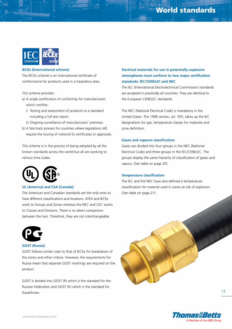
IECEx (International scheme)
The IECEx scheme is an international certificate of
conformance for products used in a hazardous area.
This scheme provides:
a) A single certification of conformity for manufacturers
which certifies:
i) Testing and assessment of products to a standard
including a full test report.
ii) Ongoing surveillance of manufacturers’ premises.
b) A fast-track process for countries where regulations still
require the issuing of national Ex certificates or approvals.
This scheme is in the process of being adopted by all the
known standards across the world but all are working to
various time scales.
UL (America) and CSA (Canada)
The American and Canadian standards are the only ones to
have different classifications and locations. ATEX and IECEx
work to Groups and Zones whereas the NEC and CEC works
to Classes and Divisions. There is no direct comparison
between the two. Therefore, they are not interchangeable.
GOST (Russia)
GOST follows similar rules to that of IECEx for breakdown of
the zones and other criteria. However, the requirements for
Russia mean that separate GOST markings are required on the
product.
GOST is divided into GOST (R) which is the standard for the
Russian Federation and GOST (K) which is the standard for
Kazakhstan.
Electrical materials for use in potentially explosive
atmospheres must conform to two major certification
standards: IEC/CENELEC and NEC
The IEC (International Electrotechnical Commission) standards
are accepted in practically all countries. They are identical to
the European CENELEC standards.
The NEC (National Electrical Code) is mandatory in the
United States. The 1996 version, art. 505, takes up the IEC
designations for gas, temperature classes for materials and
zone definition.
Gases and vapours classification
Gases are divided into four groups in the NEC (National
Electrical Code) and three groups in the IEC/CENELEC. The
groups display the same hierachy of classification of gases and
vapour. (See table on page 20).
Temperature classification
The IEC and the NEC have also defined a temperature
classificiation for material used in zones at risk of explosion.
(See table on page 21).
www.tnb-hazardous.comA Member of the ABB Group

FOR GASES & VAPOURS ZONE 0 Permanent / frequent Place in which an explosive atmosphere consisting of a mixture with air of flammable substances in the form of gas, vapour or mist is present continuously or for long periods, or frequently.
ZONE 1 Occasional Site where an atmosphere consisting of a mixture of air and inflammable substances in the form of gas, vapour or mist is likely to arise occasionally during normal operation.
Zones for onshore gases and vapours
Zone Definitions Onshore gases and vapours (as per ATEX 60079-10)
14
www.tnb-hazardous.com

SAFETY ZONELow explosion risk
ZONE 2 Gas irregular / short duration Place in which an explosive atmosphere consisting of a mixture with air and flammable substances in the form of gas, vapour or mist is not likely to occur in normal operation but, if it does occur, will persist for a short period only.
15
Zones explained
www.tnb-hazardous.comA Member of the ABB Group
16
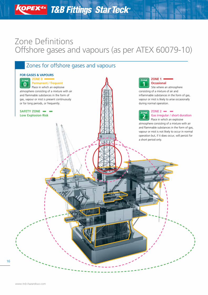
Zone DefinitionsOffshore gases and vapours (as per ATEX 60079-10)
FOR GASES & VAPOURS ZONE 0 Permanent / frequent Place in which an explosive atmosphere consisting of a mixture with air and flammable substances in the form of gas, vapour or mist is present continuously or for long periods, or frequently.
SAFETY ZONELow Explosion Risk
ZONE 1 Occasional Site where an atmosphere consisting of a mixture of air and inflammable substances in the form of gas, vapour or mist is likely to arise occasionally during normal operation.
ZONE 2 Gas irregular / short duration Place in which an explosive atmosphere consisting of a mixture with air and flammable substances in the form of gas, vapour or mist is not likely to occur in normal operation but, if it does occur, will persist for a short period only.
Zones for offshore gases and vapours
www.tnb-hazardous.com

17
Zones explained
FOR DUST
ZONE 20 Permanent / frequent Area in which an explosive atmosphere in the form of a cloud of combustible dust in air is present continuously, or for long periods, or frequently.
SAFETY ZONENo Explosion Risk
ZONE 21 Occasional Area in which an explosive atmosphere, in the form of a cloudof combustible dust in air is likely to occur, occasionally, in normal operation.
ZONE 22 Dust irregular / short duration Area in which an explosive atmosphere, in the form of a cloud of combustible dust in air is not likely to occur in normal operation but, if it does occur, will persist for a short period only.
Zone Definitions Dust (as per ATEX 60079)
Zones for Dust
www.tnb-hazardous.comA Member of the ABB Group

18
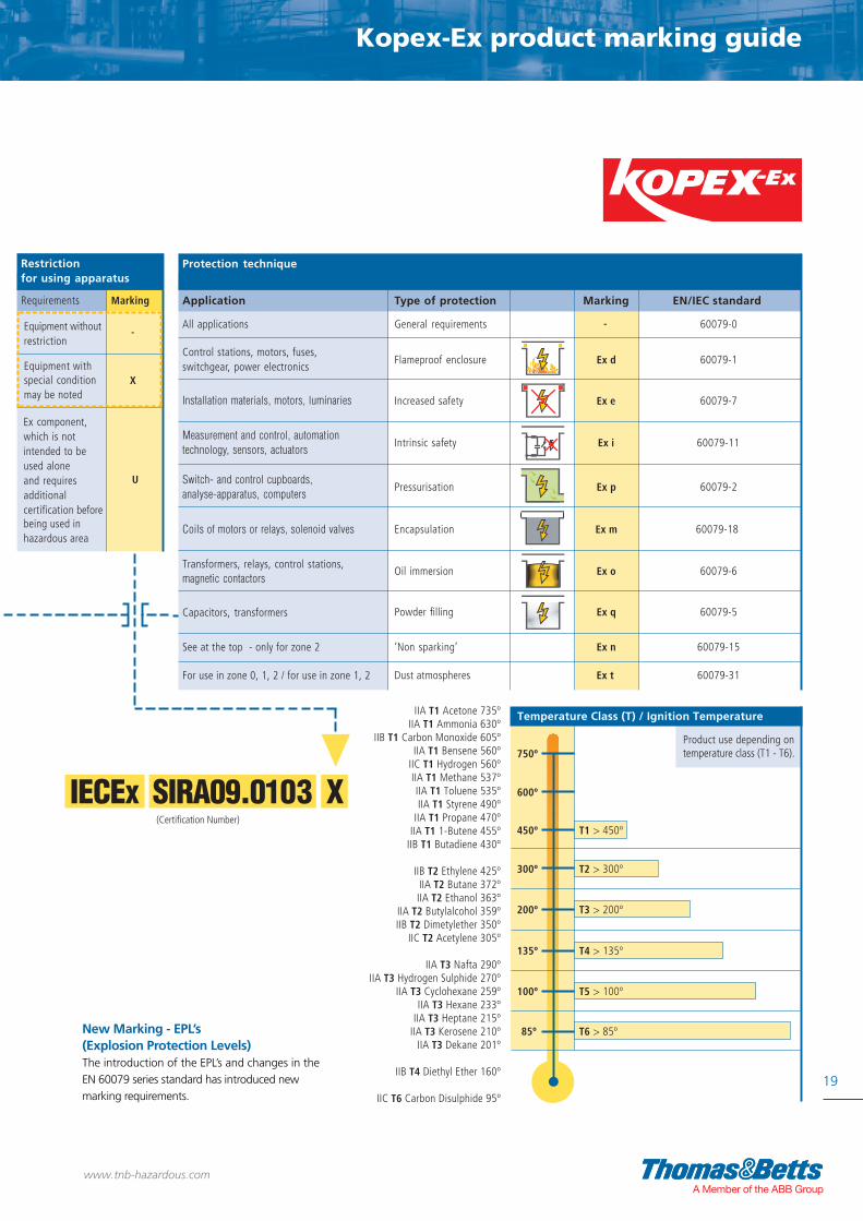
Kopex-Ex - Classification of equipmentfor use in potentially explosive atmospheres
CMPL I M2/II 2GD Exde I Mb Exde IIC Gb Extb IIIC Db
CLI.Div1.ABCD .CLII.Div1.EFG.
IECEx SIRA09.0103 X
All applications
Control stations, motors, fuses,switchgear, power electronics
Installation materials, motors, luminaries
Measurement and control, automationtechnology, sensors, actuators
Switch- and control cupboards,analyse-apparatus, computers
Coils of motors or relays, solenoid valves
Transformers, relays, control stations,magnetic contactors
Capacitors, transformers
Product use depending on temperature class (T1 - T6).
See at the top - only for zone 2
Gases or vapours
Subdivision of gases and vapours
Temperature Class (T) / Ignition Temperature
Typicalzones
Temporary behaviour offlammable substances inhazardous places
Flammablesubstances
MethaneDusts
Required marking for installation
equipment equipmentgroup protection level
IIA
IIB
IIC
Restrictionfor using apparatus
Requirements Marking
Equipment without
Equipment with
-restriction
special condition Xmay be noted
Ex component,which is notintended to beused aloneand requiresadditionalcertification before
U
being used inhazardous area
is present continuously or zone 0 II Gafor long periods or frequently
is likely to occur in normal zone 1 II Gboperation occasionally
is not likely to occur in normaloperation but, if it does occur, will zone 2 II Gcpersist for a short period only
is present continuously or for zone 20 III Dalong periods or frequently
is likely to occur in normal zone 21 III Dboperation occasionally
is not likely to occur in normaloperation but, if it does occur, zone 22 III Dcwill persist for a short period only
- mines I Ma
- mines I Mb
Dusts
GasesVapours
Apparatus maybe used in group
-
Ex d
Ex e
Ex i
Ex p
Ex m
Ex o
450º
Ex q
Ex n
60079-0
60079-1
60079-7
60079-11
60079-2
60079-18
60079-6
60079-5
60079-15
General requirements
Flameproof enclosure
Increased safety
Intrinsic safety
Pressurisation
Encapsulation
Oil immersion
Powder filling
‘Non sparking’
For use in zone 0, 1, 2 / for use in zone 1, 2 Ex t 60079-31Dust atmospheres
IIA T1 Acetone 735ºIIA T1 Ammonia 630º
IIB T1 Carbon Monoxide 605ºIIA T1 Bensene 560º
IIC T1 Hydrogen 560ºIIA T1 Methane 537ºIIA T1 Toluene 535ºIIA T1 Styrene 490º
IIA T1 Propane 470ºIIA T1 1-Butene 455º
IIB T1 Butadiene 430º
IIB T2 Ethylene 425ºIIA T2 Butane 372ºIIA T2 Ethanol 363º
IIA T2 Butylalcohol 359ºIIB T2 Dimetylether 350º
IIC T2 Acetylene 305º
IIA T3 Nafta 290ºIIA T3 Hydrogen Sulphide 270º
IIA T3 Cyclohexane 259ºIIA T3 Hexane 233º
IIA T3 Heptane 215ºIIA T3 Kerosene 210º
IIA T3 Dekane 201º
IIB T4 Diethyl Ether 160º
IIC T6 Carbon Disulphide 95º
Application Marking EN/IEC standardType of protection
Protection technique
Dust
IIIA Combustible flyingsIIIB Non-conductive dustIIIC Conductive dust
ammonia ethyl alcohol galsoline acetaldehydemethane cyclohexane n-hexaneethane n-butanepropane
town gas, ethylene ethylene ethyl-etheracrylnitril ethylene glycol
oxide
sulphide ofethinehydrogencarbon(acetylene)
(Certification Number)(Product stamp detail)
(Class & Divisions)
Classification of hazardous areas European/IEC or NEC classifications
300º
200º
135º
100º
85º
T1 > 450º
T2 > 300º
T3 > 200º
T4 > 135º
T5 > 100º
T6 > 85º
600º
750ºProduct stamp detail
CLI (Class I), Div 1 Where ignitable concentrations of flammable gases, vapours or liquids are present within the atmosphere under normal operation conditions.CLI (Class I), Div 2 Where ignitable concentrations of flammable gases, vapours or liquids are present within the atmosphere under abnormal operation conditions.Class I areas Group A: Acetylene / Group B: Hydrogen / Group C: Propane & Ethylene / Group D: Benzene, Butane & Propane.
CLII (Class II), Div 1 Where ignitable concentrations of combustible dusts are present within the atmosphere under normal operation conditions.CLII (Class II), Div 2 Where ignitable concentrations of combustible dusts are present within the atmosphere under abnormal operation conditions. Class II areas Group E: Metal Dust / Group F: Carbon & Charcoal / Group G: Flour, Starch, Wood & Plastic.
www.tnb-hazardous.com
Kopex-Ex product marking guide
CMPL I M2/II 2GD Exde I Mb Exde IIC Gb Extb IIIC Db
CLI.Div1.ABCD .CLII.Div1.EFG.
IECEx SIRA09.0103 X
All applications
Control stations, motors, fuses,switchgear, power electronics
Installation materials, motors, luminaries
Measurement and control, automationtechnology, sensors, actuators
Switch- and control cupboards,analyse-apparatus, computers
Coils of motors or relays, solenoid valves
Transformers, relays, control stations,magnetic contactors
Capacitors, transformers
Product use depending on temperature class (T1 - T6).
See at the top - only for zone 2
Gases or vapours
Subdivision of gases and vapours
Temperature Class (T) / Ignition Temperature
Typicalzones
Temporary behaviour offlammable substances inhazardous places
Flammablesubstances
MethaneDusts
Required marking for installation
equipment equipmentgroup protection level
IIA
IIB
IIC
Restrictionfor using apparatus
Requirements Marking
Equipment without
Equipment with
-restriction
special condition Xmay be noted
Ex component,which is notintended to beused aloneand requiresadditionalcertification before
U
being used inhazardous area
is present continuously or zone 0 II Gafor long periods or frequently
is likely to occur in normal zone 1 II Gboperation occasionally
is not likely to occur in normaloperation but, if it does occur, will zone 2 II Gcpersist for a short period only
is present continuously or for zone 20 III Dalong periods or frequently
is likely to occur in normal zone 21 III Dboperation occasionally
is not likely to occur in normaloperation but, if it does occur, zone 22 III Dcwill persist for a short period only
- mines I Ma
- mines I Mb
Dusts
GasesVapours
Apparatus maybe used in group
-
Ex d
Ex e
Ex i
Ex p
Ex m
Ex o
450º
Ex q
Ex n
60079-0
60079-1
60079-7
60079-11
60079-2
60079-18
60079-6
60079-5
60079-15
General requirements
Flameproof enclosure
Increased safety
Intrinsic safety
Pressurisation
Encapsulation
Oil immersion
Powder filling
‘Non sparking’
For use in zone 0, 1, 2 / for use in zone 1, 2 Ex t 60079-31Dust atmospheres
IIA T1 Acetone 735ºIIA T1 Ammonia 630º
IIB T1 Carbon Monoxide 605ºIIA T1 Bensene 560º
IIC T1 Hydrogen 560ºIIA T1 Methane 537ºIIA T1 Toluene 535ºIIA T1 Styrene 490º
IIA T1 Propane 470ºIIA T1 1-Butene 455º
IIB T1 Butadiene 430º
IIB T2 Ethylene 425ºIIA T2 Butane 372ºIIA T2 Ethanol 363º
IIA T2 Butylalcohol 359ºIIB T2 Dimetylether 350º
IIC T2 Acetylene 305º
IIA T3 Nafta 290ºIIA T3 Hydrogen Sulphide 270º
IIA T3 Cyclohexane 259ºIIA T3 Hexane 233º
IIA T3 Heptane 215ºIIA T3 Kerosene 210º
IIA T3 Dekane 201º
IIB T4 Diethyl Ether 160º
IIC T6 Carbon Disulphide 95º
Application Marking EN/IEC standardType of protection
Protection technique
Dust
IIIA Combustible flyingsIIIB Non-conductive dustIIIC Conductive dust
ammonia ethyl alcohol galsoline acetaldehydemethane cyclohexane n-hexaneethane n-butanepropane
town gas, ethylene ethylene ethyl-etheracrylnitril ethylene glycol
oxide
sulphide ofethinehydrogencarbon(acetylene)
(Certification Number)(Product stamp detail)
(Class & Divisions)
Classification of hazardous areas European/IEC or NEC classifications
300º
200º
135º
100º
85º
T1 > 450º
T2 > 300º
T3 > 200º
T4 > 135º
T5 > 100º
T6 > 85º
600º
750ºProduct stamp detail
New Marking - EPL’s (Explosion Protection Levels)The introduction of the EPL’s and changes in the EN 60079 series standard has introduced new marking requirements.
19
www.tnb-hazardous.comA Member of the ABB Group

20
Star Teck® - Classification of equipmentfor use in potentially explosive atmospheres
All applications
Control stations, motors, fuses,switchgear, power electronics
Installation materials, motors, luminaires
Measurement and control, automationtechnology, sensors, actuators
Switch- and control cupboards,analyse-apparatus, computers
Coils of motors or relays, solenoid valves
Transformers, relays, control stations,magnetic contactors
Capacitors, transformers
Product use depending on temperature class (T1 - T6).
See at the top - only for zone 2
Gases or vapours
Subdivision of gases and vapours
Temperature Class (T) / Ignition Temperature
Typicalzones
Temporary behaviour offlammable substances inhazardous places
Flammablesubstances
MethaneDusts
Required marking for installation
equipment equipmentgroup protection level
IIA
IIB
IIC
Restrictionfor using apparatus
Requirements Marking
Equipment without
Equipment with
-restriction
special condition Xmay be noted
Ex component,which is notintended to beused aloneand requiresadditionalcertification before
U
being used inhazardous area
is present continuously or zone 0 II Gafor long periods or frequently
is likely to occur in normal zone 1 II Gboperation occasionally
is not likely to occur in normaloperation but, if it does occur, will zone II Gcpersist for a short period only
is present continuously or for zone 20 III Dalong periods or frequently
is likely to occur in normal zone 21 III Dboperation occasionally
is not likely to occur in normaloperation but, if it does occur, zone 22 III Dcwill persist for a short period only
- mines I Ma
- mines I Mb
Dusts
GasesVapours
Temperature Class (T) / Ignition Temperature
Apparatus maybe used in group
-
Ex d
Ex e
Ex i
Ex p
Ex m
Ex o
450º
Ex q
Ex n
60079-0
60079-1
60079-7
60079-11
60079-2
60079-18
60079-6
60079-5
60079-15
General requirements
Flameproof enclosure
Increased safety
Intrinsic safety
Pressurisation
Encapsulation
Oil immersion
Powder filling
‘Non sparking’
For use in zone 0, 1, 2 / for use in zone 1, 2 Ex t 60079-31Dust atmospheres
IIA T1 Acetone 735ºIIA T1 Ammonia 630º
IIB T1 Carbon Monoxide 605ºIIA T1 Bensene 560º
IIC T1 Hydrogen 560ºIIA T1 Methane 537ºIIA T1 Toluene 535ºIIA T1 Styrene 490º
IIA T1 Propane 470ºIIA T1 1-Butene 455º
IIB T1 Butadiene 430º
IIB T2 Ethylene 425ºIIA T2 Butane 372ºIIA T2 Ethanol 363º
IIA T2 Butylalcohol 359ºIIB T2 Dimetylether 350º
IIC T2 Acetylene 305º
IIA T3 Nafta 290ºIIA T3 Hydrogen Sulphide 270º
IIA T3 Cyclohexane 259ºIIA T3 Hexane 233º
IIA T3 Heptane 215ºIIA T3 Kerosene 210º
IIA T3 Dekane 201º
IIB T4 Diethyl Ether 160º
IIC T6 Carbon Disulphide 95º
Application Marking EN/IEC standardType of protection
Protection technique
Dust
IIIA Combustible flyingsIIIB Non-conductive dustIIIC Conductive dust
ammonia ethyl alcohol gasoline acetaldehydemethane cyclohexane n-hexaneethane n-butanepropane
town gas, ethylene ethylene ethyl-etheracrylnitril ethylene glycol
oxide
sulphide ofethinehydrogencarbon(acetylene)
Classification of hazardous areas European/IEC or NEC classifications
Watertight Star Teck Star Teck XP Star Teck Extreme Star Teck Extreme Star Teck Extreme XP10464 Series ST050 to ST400 STX050 to STX400 STE050 to STE200 STE250 to STE400 STEX050 to STEX400
group protection level
Zone 1 Group IIC, IIB, IIA
Division 1 Group A, B, C, D
Zone 2 Group IIC, IIB, IIA
Division 2 Group A, B, C, D
Zone 1 Group IIC, IIB, IIA
Division 1 Group A, B, C, D
Zone 2 Group IIC, IIB, IIA
Division 2 Group A, B, C, D
Class II
Division 1, 2
Groups E, F, G
Class III
Division 1, 2
Enclosure Type 6P
(immersion)
Enclosure Type 4
(immersion)
Not Certified
Not Certified
Not Certified
Certified
Certified
Certified
Certified
Certified
Not Certified
Certified
Certified
Certified
Not Certified
Certified
Certified
Certified
Certified
Certified
Certified
Certified Not Certified
Certified
Certified
Certified
Not Certified
Certified
Certified
Certified
Not Certified
Not Certified
Certified
Certified
Certified
Certified
Certified
Certified
Not Certified
Not required - certified with integral seal
Not required - certified with integral seal
Not required - certified with integral seal
Not required - certified with integral seal
Not Certified
Certified
Certified
Not Certified
Not Certified
Certified
Certified
Class I IEC Zone System - CEC Division (pre-1998) System
Classes II and III, Divisions 1 and 2
300º
200º
135º
100º
85º
T1 > 450º
T2 > 300º
T3 > 200º
T4 > 135º
T5 > 100º
T6 > 85º
600º
750º
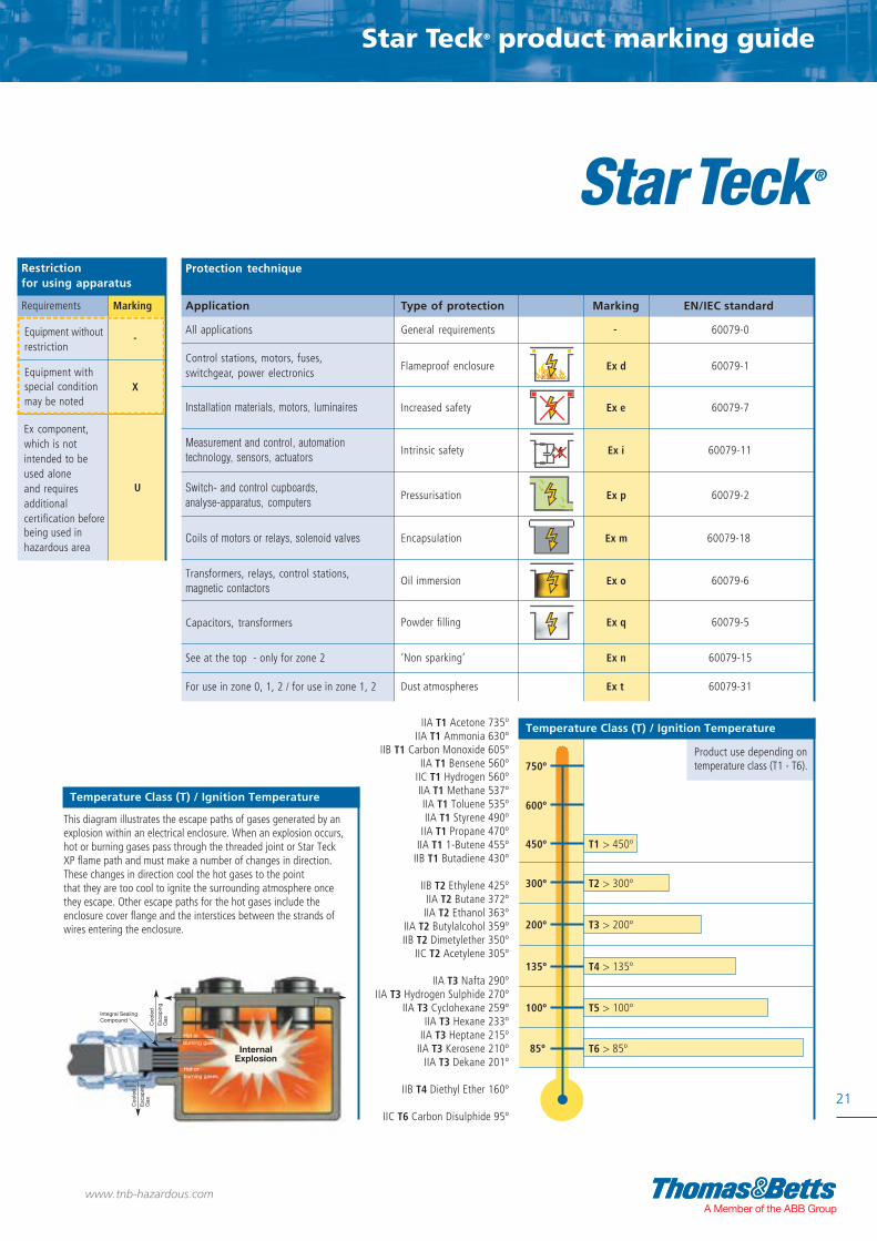
This diagram illustrates the escape paths of gases generated by an explosion within an electrical enclosure. When an explosion occurs, hot or burning gases pass through the threaded joint or Star Teck XP flame path and must make a number of changes in direction. These changes in direction cool the hot gases to the point that they are too cool to ignite the surrounding atmosphere once they escape. Other escape paths for the hot gases include the enclosure cover flange and the interstices between the strands of wires entering the enclosure.
With SC4-KIT, SC65 Integral Sealing Compound
With Class 1 HLA Sealing Fitting
www.tnb-hazardous.com
Star Teck® product marking guide
Star Teck® - Classification of equipmentfor use in potentially explosive atmospheres
All applications
Control stations, motors, fuses,switchgear, power electronics
Installation materials, motors, luminaires
Measurement and control, automationtechnology, sensors, actuators
Switch- and control cupboards,analyse-apparatus, computers
Coils of motors or relays, solenoid valves
Transformers, relays, control stations,magnetic contactors
Capacitors, transformers
Product use depending on temperature class (T1 - T6).
See at the top - only for zone 2
Gases or vapours
Subdivision of gases and vapours
Temperature Class (T) / Ignition Temperature
Typicalzones
Temporary behaviour offlammable substances inhazardous places
Flammablesubstances
MethaneDusts
Required marking for installation
equipment equipmentgroup protection level
IIA
IIB
IIC
Restrictionfor using apparatus
Requirements Marking
Equipment without
Equipment with
-restriction
special condition Xmay be noted
Ex component,which is notintended to beused aloneand requiresadditionalcertification before
U
being used inhazardous area
is present continuously or zone 0 II Gafor long periods or frequently
is likely to occur in normal zone 1 II Gboperation occasionally
is not likely to occur in normaloperation but, if it does occur, will zone II Gcpersist for a short period only
is present continuously or for zone 20 III Dalong periods or frequently
is likely to occur in normal zone 21 III Dboperation occasionally
is not likely to occur in normaloperation but, if it does occur, zone 22 III Dcwill persist for a short period only
- mines I Ma
- mines I Mb
Dusts
GasesVapours
Temperature Class (T) / Ignition Temperature
Apparatus maybe used in group
-
Ex d
Ex e
Ex i
Ex p
Ex m
Ex o
450º
Ex q
Ex n
60079-0
60079-1
60079-7
60079-11
60079-2
60079-18
60079-6
60079-5
60079-15
General requirements
Flameproof enclosure
Increased safety
Intrinsic safety
Pressurisation
Encapsulation
Oil immersion
Powder filling
‘Non sparking’
For use in zone 0, 1, 2 / for use in zone 1, 2 Ex t 60079-31Dust atmospheres
IIA T1 Acetone 735ºIIA T1 Ammonia 630º
IIB T1 Carbon Monoxide 605ºIIA T1 Bensene 560º
IIC T1 Hydrogen 560ºIIA T1 Methane 537ºIIA T1 Toluene 535ºIIA T1 Styrene 490º
IIA T1 Propane 470ºIIA T1 1-Butene 455º
IIB T1 Butadiene 430º
IIB T2 Ethylene 425ºIIA T2 Butane 372ºIIA T2 Ethanol 363º
IIA T2 Butylalcohol 359ºIIB T2 Dimetylether 350º
IIC T2 Acetylene 305º
IIA T3 Nafta 290ºIIA T3 Hydrogen Sulphide 270º
IIA T3 Cyclohexane 259ºIIA T3 Hexane 233º
IIA T3 Heptane 215ºIIA T3 Kerosene 210º
IIA T3 Dekane 201º
IIB T4 Diethyl Ether 160º
IIC T6 Carbon Disulphide 95º
Application Marking EN/IEC standardType of protection
Protection technique
Dust
IIIA Combustible flyingsIIIB Non-conductive dustIIIC Conductive dust
ammonia ethyl alcohol gasoline acetaldehydemethane cyclohexane n-hexaneethane n-butanepropane
town gas, ethylene ethylene ethyl-etheracrylnitril ethylene glycol
oxide
sulphide ofethinehydrogencarbon(acetylene)
Classification of hazardous areas European/IEC or NEC classifications
Watertight Star Teck Star Teck XP Star Teck Extreme Star Teck Extreme Star Teck Extreme XP10464 Series ST050 to ST400 STX050 to STX400 STE050 to STE200 STE250 to STE400 STEX050 to STEX400
group protection level
Zone 1 Group IIC, IIB, IIA
Division 1 Group A, B, C, D
Zone 2 Group IIC, IIB, IIA
Division 2 Group A, B, C, D
Zone 1 Group IIC, IIB, IIA
Division 1 Group A, B, C, D
Zone 2 Group IIC, IIB, IIA
Division 2 Group A, B, C, D
Class II
Division 1, 2
Groups E, F, G
Class III
Division 1, 2
Enclosure Type 6P
(immersion)
Enclosure Type 4
(immersion)
Not Certified
Not Certified
Not Certified
Certified
Certified
Certified
Certified
Certified
Not Certified
Certified
Certified
Certified
Not Certified
Certified
Certified
Certified
Certified
Certified
Certified
Certified Not Certified
Certified
Certified
Certified
Not Certified
Certified
Certified
Certified
Not Certified
Not Certified
Certified
Certified
Certified
Certified
Certified
Certified
Not Certified
Not required - certified with integral seal
Not required - certified with integral seal
Not required - certified with integral seal
Not required - certified with integral seal
Not Certified
Certified
Certified
Not Certified
Not Certified
Certified
Certified
Class I IEC Zone System - CEC Division (pre-1998) System
Classes II and III, Divisions 1 and 2
300º
200º
135º
100º
85º
T1 > 450º
T2 > 300º
T3 > 200º
T4 > 135º
T5 > 100º
T6 > 85º
600º
750º
This diagram illustrates the escape paths of gases generated by an explosion within an electrical enclosure. When an explosion occurs, hot or burning gases pass through the threaded joint or Star Teck XP flame path and must make a number of changes in direction. These changes in direction cool the hot gases to the point that they are too cool to ignite the surrounding atmosphere once they escape. Other escape paths for the hot gases include the enclosure cover flange and the interstices between the strands of wires entering the enclosure.
With SC4-KIT, SC65 Integral Sealing Compound
With Class 1 HLA Sealing Fitting
21
www.tnb-hazardous.comA Member of the ABB Group
Hot or burning gases
Hot or burning gases
Coo
led
Esc
apin
g G
as
Integral SealingCompound
InternalExplosion
Coo
led
Esc
apin
g G
as
Hot or burning gases
Hot or burning gases
Coo
led
Esc
apin
g G
as
Integral SealingCompound
InternalExplosion
Coo
led
Esc
apin
g G
as

IP suitability ratings are a system for classifying the degree of protection provided by enclosures of electrical equipment. The higher the number, the greaterthe degree of protection; they apply ONLY to properly installed equipment. The numerals stand for the following:
Protection against Solid Bodies
Degree of protection for persons against access to hazardous parts insidethe enclosure and/or against the ingress of solid foreign objects.
Protection against Water
Degree of protection of equipment inside enclosures against damage fromthe ingress of water.
0 No protection
Ingress Protection (IP) Rating according to EN 60529/DIN 40050
IP 6 8 IP 6 8
1 Objects greater than 50 mm, accidental touch by hands
2 Objects greater than 12 mm, accidental touch by fingers
3 Objects greater than 2.5 mm, e.g. tools/wires
4 Objects greater than 1 mm, e.g. tools/wires/small wires
5 Protected against dust - limited ingress (no harmful deposits)
6 Totally protected against dust (Dust-tight)
0 No protection
1 Protected against vertically falling drops of water
2 Protected against direct sprays of water up to 15°from vertical
3 Protected against sprays of water to 60° from vertical
4 Protected against water sprayed from all directions -limited ingress permitted
5 Protected against low pressure jets of water from alldirections - limited ingress permitted
6 Protected against strong pressure jets of water, heavyseas- limited ingress permitted
7 Protection against the Effects of immersion between 15cm - 1 m
8 Protection against long periods of immersion under aquoted pressure. E.g. 2 bar at 24 hours
9kIP69k Automotive standard DIN40050 and signifiesresistance to high pressure jets of water (up to 80bar)from any angle.
The first digit stands for:Protection against Dust
The second digit stands for:Protection against Water
installation but is notsuitable as a rotating
joint in constantlymoving applications
rotating joint withinconstantly moving
applications
Index of ingress protection
IP suitability ratings are a system for classifying the degree of protection provided by enclosures of electrical equipment. The higher the number, the greaterthe degree of protection; they apply ONLY to properly installed equipment. The numerals stand for the following:
Protection against Solid Bodies
Degree of protection for persons against access to hazardous parts insidethe enclosure and/or against the ingress of solid foreign objects.
Protection against Water
Degree of protection of equipment inside enclosures against damage fromthe ingress of water.
0 No protection
Ingress Protection (IP) Rating according to EN 60529/DIN 40050
IP 6 8 IP 6 8
1 Objects greater than 50 mm, accidental touch by hands
2 Objects greater than 12 mm, accidental touch by fingers
3 Objects greater than 2.5 mm, e.g. tools/wires
4 Objects greater than 1 mm, e.g. tools/wires/small wires
5 Protected against dust - limited ingress (no harmful deposits)
6 Totally protected against dust (Dust-tight)
0 No protection
1 Protected against vertically falling drops of water
2 Protected against direct sprays of water up to 15°from vertical
3 Protected against sprays of water to 60° from vertical
4 Protected against water sprayed from all directions -limited ingress permitted
5 Protected against low pressure jets of water from alldirections - limited ingress permitted
6 Protected against strong pressure jets of water, heavyseas- limited ingress permitted
7 Protection against the Effects of immersion between 15cm - 1 m
8 Protection against long periods of immersion under aquoted pressure. E.g. 2 bar at 24 hours
9kIP69k Automotive standard DIN40050 and signifiesresistance to high pressure jets of water (up to 80bar)from any angle.
The first digit stands for:Protection against Dust
The second digit stands for:Protection against Water
installation but is notsuitable as a rotating
joint in constantlymoving applications
rotating joint withinconstantly moving
applications
22
IPxx suitability ratings are a system for classifying the
degree of protection provided by enclosures of electrical
equipment. The higher the number, the greater the
degree of protection, in accordance with standards
IEC 60529 and EN 60529.
Protection standrards
• Protection against solid bodies
• Protection against liquids
• Protection against impact as per EN 50102 standard
Protection against solid bodies Protection against liquids
0
1
2
03
04
05
6
0
1
2
3
4
5
6
7
8
9
No protection
Protected against solid bodies of 50mm and greater, (e.g. accidental contact with the hand)
Protected against solid bodies of 12.5mm and greater, (e.g. accidental touch by fingers)
Protected against solid bodies of 2.5mm and greater, (e.g. tools and wires)
Protected against solid bodies of 1mm or greater, (e.g. thin tools and fine wires)
Protected against dust - limited ingress (no harmfull deposits)
Totally protected against dust(dust-tight)
No protection
Protected against vertically falling drops of water (condensation)
Protected against drops of water falling up to 15º from the vertical
Protected against drops of water falling up to 60º from the vertical
Protected against splashing water from all directions
Protection against jets of water from all directions
Protection against powerful jets of water from all directions
The first digit stands for protection against
solid bodies
The second digit stands for protection
against water
IP Classification
Protected against the effects of temporary immersion in water
Protected against the continuous effects of immersion in water havingregard to specific conditions
IP69k automotive standard DIN40050 signifies resistance to high pressure jets (up to 80bar) from any angle
Index ofingress protection IP suitability ratings are a system for classifying the degree of protection provided by enclosures of electrical equipment. The higher the number, the greater
the degree of protection; they apply ONLY to properly installed equipment. The numerals stand for the following:
Protection against Solid Bodies
Degree of protection for persons against access to hazardous parts insidethe enclosure and/or against the ingress of solid foreign objects.
Protection against Water
Degree of protection of equipment inside enclosures against damage fromthe ingress of water.
0 No protection
Ingress Protection (IP) Rating according to EN 60529/DIN 40050
IP 6 8 IP 6 8
1 Objects greater than 50 mm, accidental touch by hands
2 Objects greater than 12 mm, accidental touch by fingers
3 Objects greater than 2.5 mm, e.g. tools/wires
4 Objects greater than 1 mm, e.g. tools/wires/small wires
5 Protected against dust - limited ingress (no harmful deposits)
6 Totally protected against dust (Dust-tight)
0 No protection
1 Protected against vertically falling drops of water
2 Protected against direct sprays of water up to 15°from vertical
3 Protected against sprays of water to 60° from vertical
4 Protected against water sprayed from all directions -limited ingress permitted
5 Protected against low pressure jets of water from alldirections - limited ingress permitted
6 Protected against strong pressure jets of water, heavyseas- limited ingress permitted
7 Protection against the Effects of immersion between 15cm - 1 m
8 Protection against long periods of immersion under aquoted pressure. E.g. 2 bar at 24 hours
9kIP69k Automotive standard DIN40050 and signifiesresistance to high pressure jets of water (up to 80bar)from any angle.
The first digit stands for:Protection against Dust
The second digit stands for:Protection against Water
installation but is notsuitable as a rotating
joint in constantlymoving applications
rotating joint withinconstantly moving
applications
IP
IP suitability ratings are a system for classifying the degree of protection provided by enclosures of electrical equipment. The higher the number, the greaterthe degree of protection; they apply ONLY to properly installed equipment. The numerals stand for the following:
Protection against Solid Bodies
Degree of protection for persons against access to hazardous parts insidethe enclosure and/or against the ingress of solid foreign objects.
Protection against Water
Degree of protection of equipment inside enclosures against damage fromthe ingress of water.
0 No protection
Ingress Protection (IP) Rating according to EN 60529/DIN 40050
IP 6 8 IP 6 8
1 Objects greater than 50 mm, accidental touch by hands
2 Objects greater than 12 mm, accidental touch by fingers
3 Objects greater than 2.5 mm, e.g. tools/wires
4 Objects greater than 1 mm, e.g. tools/wires/small wires
5 Protected against dust - limited ingress (no harmful deposits)
6 Totally protected against dust (Dust-tight)
0 No protection
1 Protected against vertically falling drops of water
2 Protected against direct sprays of water up to 15°from vertical
3 Protected against sprays of water to 60° from vertical
4 Protected against water sprayed from all directions -limited ingress permitted
5 Protected against low pressure jets of water from alldirections - limited ingress permitted
6 Protected against strong pressure jets of water, heavyseas- limited ingress permitted
7 Protection against the Effects of immersion between 15cm - 1 m
8 Protection against long periods of immersion under aquoted pressure. E.g. 2 bar at 24 hours
9kIP69k Automotive standard DIN40050 and signifiesresistance to high pressure jets of water (up to 80bar)from any angle.
The first digit stands for:Protection against Dust
The second digit stands for:Protection against Water
installation but is notsuitable as a rotating
joint in constantlymoving applications
rotating joint withinconstantly moving
applications
6 77 =
www.tnb-hazardous.com

Hazlux catalogue
23
www.tnb-hazardous.comA Member of the ABB Group
Introducing the NEW Hazlux® industrial and hazardous location lighting catalogue
Call now to order! our NEW industrial and hazardous location lighting product catalogue on tel +44 (0) 1675 468 213 or visit our website at www.tnb-hazardous.com
Thomas & Betts is committed to delivering high quality
industrial lighting fixtures designed, tested and
certified for use in hazardous locations and adverse
environment conditions.
You can rely on Hazlux® to safely provide light where
you need it - even under the harshest indoor and outdoor
conditions. If safety, labour reduction, quality and
reliability are your priorities, consider Hazlux® lighting
products to reduce maintenance and prevent downtimes.
Specifically designed and approved to UL and
CSA for the North American market.

2624
www.tnb-hazardous.com
Conduit systems

Conduit systems
25
www.tnb-hazardous.comA Member of the ABB Group

26
Conduit fittings - selection guide
www.tnb-hazardous.com
Nylon conduits EXB Page 28
Prot
ectio
n Ty
peG
asG
roup
Dus
tG
roup
Zo
nes
1DIV
2DIVI
2DIV
1DIV
Nylon Conduits
Nylon Conduit Fittings
Overbraided conduits EXBB Page 28
Metallicfittings Page 30
Nylon conduits XESX Page 29
Nylonfittings NENV Page 33
Nylonfittings Page 34
Nylonfittings Page 35
Nylonfittings Page 36

Conduit fittings - selection guide
27
www.tnb-hazardous.comA Member of the ABB Group
For use with liquid tight conduits
Group 1 glands Page 42
Group 1 90º elbow glands Page 44
Group 1 universal swivel fttings Page 47
XP flex Page 48
Group 1 univeral fittings Page 45
Liquid tight conduits Page 38

Technical specifications
28
EXPQM fitting 30
Related products
EXBQM fitting 30
www.tnb-hazardous.com
Non-metallic nylon conduit
EXB anti-static conduit compatible with EXPQM / EXPQA fittings
Anti-Static Nylon 12 (Black) Conduit Size (mm) Outside Coil LengthsType Metric NW Diameter (mm) (m)
EXB03* 16 12 15.8 10/30/50
EXB04* 20 17 21.2 10/30/50
EXB05* 25 23 28.5 10/30/50
EXB06* 32 29 34.4 10/30/50
EXB07* 40 36 42.4 10/30/50
EXB08* 50 48 54.5 10/30/50
EXB09* 68 56 67.2 10/30/50
EXB010* 80 70 80 10/30/50
*Add coil length to complete part number, e.g. 10 metres = EXB0510
EC TYPE Examination Certificate:ATEX: Baseefa 08 ATEX 0003XIECEx: IECEx BAS08.0001XGOST R: POCC GB.ГБ05.B03850INMETRO: TÜV 11.0091
Ex e IIC GbEx tb IIIC DbTemperature: -20°C to 80ºCRTI 110ºC to EN60079-0
Special characteristics EXB: Surface resistivity <106Ω
EXBB overbraided conduit compatible with EXBQM / EXBQA fittings
Anti-Static Nylon 12 (Stainless Steel) Conduit Size (mm) Outside Coil LengthsType Metric NW Diameter (mm) (m)
EXBB03* 16 12 17.2 50
EXBB04* 20 17 23.6 50
EXBB05* 25 23 30 50
EXBB06* 32 29 36 50
EXBB07* 40 36 43.5 30
EXBB08* 50 48 56.5 30
*Add coil length to complete part number, e.g. 10 metres = EXBB0510
EC TYPE Examination Certificate:ATEX: Baseefa 08 ATEX 0003XIECEx: IECEx BAS08.0001XGOST R: POCC GB.ГБ05.B03850INMETRO: TÜV 11.0091
Ex e IIC GbEx tb IIIC DbTemperature: -20°C to 80ºCRTI 110ºC to EN60079-0
Special characteristics EXBB: Screening level 60dB at 1MHz

Non-metallic nylon conduit - EXB / EXBB / XESX range
29
www.tnb-hazardous.comA Member of the ABB Group
Technical specifications
XESX anti-static nylon multi-layer conduit compatible with EXPQM / EXBQA fittings
Anti-Static Nylon 12 (Black) Conduit Size (mm) Outside Coil Lengths
Type Metric NW Diameter (mm) (m)
XESX0250 12 10 12.8 50
XESX0350 16 12 15.6 50
XESX0450 20 17 21 50
XESX0550 25 23 28.5 50
XESX0650 32 29 34.4 50
XESX0730 40 36 42.4 30
XESX0830 50 48 54.4 30
Related products
NENV fitting 33 NENZ fitting 33 NEBV fitting 34 NEWV fitting 34 NEAV fitting 34
EC TYPE Examination Certificate:ATEX: Baseefa 08 ATEX 0003XIECEx: IECEx BAS08.0001X
Ex e IIC GbEx tb IIIC DbTemperature: -40°C to 85ºC
RTI 110ºC to EN60079-0Special characteristics XESX: Surface resistivity <106Ω
Anti-Static Nylon 12 (Black) Conduit Size (mm) Outside Coil LengthsType Metric NW Diameter (mm) (m)
XESXT-10BY.50 12 10 12.8 50
XESXT-12BY.50 16 12 15.6 50
XESXG-17BY.50 20 17 21 50
XESXG-23BY.50 25 23 28.5 50
XESXG-29BY.50 32 29 34.4 50
XESXG-36BY.30 40 36 42.4 30
XESXG-48BY.30 50 48 54.4 30
XESX anti-static conduit compatible with all nylon fittings
EC TYPE Examination Certificate: ATEX SEV 05 ATEX0105
Ex eb IIC GbEx tb IIIC Db
EXPQM fitting 30 EXBQM fitting 30
Related products
Temperature: -40°C to 85ºC Special characteristics: XESX: Surface resistivity <106Ω

• Manufactured in nickel plated brass
• Approved for use in Ex e applications for
Zones 1, 2, 21 & 22
Approvals / Characteristics Features
30
EXBQM / EXPQA rangeNylon conduit fittings
EC TYPE Examination Certificate:ATEX: Baseefa 08 ATEX 0003XIECEx: IECEx BAS08.0001XGOST R: POCC GB.ГБ05.B03850INMETRO: TÜV 11.0091Ex e IIC GbEx tb IIIC DbTemperature: -40°C to 85ºC
Certification and standards
www.tnb-hazardous.com

Dimensions
Non-metallic nylon fittings - EXPQM / EXBQA range
Technical specifications
31
Related products
For accessories see pages 134-35
Locknuts 134 Sealing 135Washers
EXB Range 28 EXBB Range 28 XESX Multi-Layer 29
www.tnb-hazardous.comA Member of the ABB Group
Nickel Plated Brass Metric Cable Gland Dimensions Type Thread Size A Conduit Size B C D E L H CH1 CH2
EXPQM0303 M16 16.0 11.4 27.4 25.9 16.0 33.3 25.4 24.0
EXPQM0404 M20 21.0 15.8 30.2 30.2 16.0 32.0 28.0 28.0
EXPQM0505 M25 28.0 19.0 41.0 41.0 16.0 39.0 38.0 38.0
EXPQM0606 M32 34.0 26.4 48.1 45.4 17.0 40.0 44.5 42.0
EXPQM0707 M40 42.0 32.9 61.6 58.3 17.0 49.5 57.0 54.0
EXPQM0808 M50 54.0 43.9 75.6 75.6 16.0 48.0 70.0 70.0
EXPQM0909 M63 63.0 56.0 91.8 91.8 16.0 54.6 84.0 84.0
EXPQM1010 M75 80.0 67.5 104.0 104.0 16.0 52.6 95.3 95.3
EXBQM0303 M16 16.0 11.4 33.2 26.6 18.0 43.5 30.0 24.0
EXBQM0404 M20 21.0 15.8 38.8 31.0 16.0 43.5 35.0 28.0
EXBQM0505 M25 28.0 19.0 49.3 42.1 16.0 50.0 44.5 38.0
EXBQM0606 M32 34.0 26.4 55.4 46.5 18.0 51.0 50.0 42.0
EXBQM0707 M40 42.0 32.9 77.6 59.8 18.0 67.5 70.0 54.0
EXBQM0808 M50 54.0 43.9 93.1 77.6 16.0 70.0 84.0 70.0
Nickel Plated Brass NPT Cable Gland Dimensions Type Thread Size A Conduit Size B C D E L H CH1 CH2
EXPQA0304 1/2” NPT 16.0 11.4 25.9 27.4 20.0 32.5 24.0 25.4
EXPQA0404 1/2” NPT 21.0 15.8 30.2 30.2 20.0 31.5 28.0 28.0
EXPQA0505 3/4” NPT 28.0 19.0 41.0 41.0 20.2 38.3 38.0 38.0
EXPQA0606 1” NPT 34.0 26.4 45.4 48.1 24.2 40.0 42.0 44.5
EXPQA0707 1 1/4” NPT 42.0 32.9 58.3 61.6 25.8 49.5 54.0 57.0
EXPQA0808 1 1/2” NPT 54.0 40.7 75.6 75.6 26.1 48.0 70.0 70.0
EXPQA0909 2” NPT 63.0 56.0 91.8 91.8 19.7 54.6 84.0 84.0
EXPQA1010 2 1/2” NPT 80.0 67.5 104.0 104.0 28.9 52.6 95.3 95.3
EXBQA0304 1/2” NPT 16.0 11.4 33.2 26.6 20.0 44.5 30.0 24.0
EXBQA0404 1/2” NPT 21.0 15.8 38.8 31.0 20.0 45.0 35.0 28.0
EXBQA0505 3/4” NPT 28.0 19.0 49.3 42.1 20.2 54.0 44.5 38.0
EXBQA0606 1” NPT 34.0 26.4 55.4 46.5 24.2 57.5 50.0 42.0
EXBQA0707 2” NPT 42.0 32.9 77.6 59.8 25.8 70.0 70.0 54.0
EXBQA0808 2 1/2” NPT 54.0 40.7 93.1 77.6 26.1 70.0 84.0 70.0
EXPQM for unbraided nylon EXBQA for braided nylon

• Manufactured in modified nylon 12 with nickel
plated brass threads
• Approved for use in Ex e applications for
Zones 1, 2, 21 & 22
Approvals / Characteristics Features
32
Nylon conduit fittingsNylon conduit fittings for XESX conduit ( only)
EC TYPE Examination Certificate:ATEX: SEV 05 ATEX 0105Ex eb IICEx tb IIICTemperature: -20°C to 85ºC
Certification and standards
www.tnb-hazardous.com

XESX range 29
NENV straight male conduit fitting
Non-metallic nylon fittings for XESX conduit ( only)
Technical specifications
33
Related products
NENZ straight male conduit fitting with strain relief
Locknuts 134
Conduit Size (mm) Metric ThreadType - Metric Metric NW Size (mm)
NENV-M120-10 12 10 12
NENV-M160-10 12 10 16
NENV-M162-10 16 12 16
NENV-M202-10 16 12 20
NENV-M207-10 20 17 20
NENV-M257-11 20 17 25
NENV-M253-11 25 23 25
NENV-M323-13 25 23 32
NENV-M329-13 32 29 32
NENV-M409-13 32 29 40
NENV-M406-13 40 36 40
NENV-M506-14 40 36 50
NENV-M508-14 50 48 50
NENV-M638-14 50 48 63
Conduit Size (mm) Metric ThreadType - Metric Metric NW Size (mm)
NENZ-M120S/P* 12 10 12
NENZ-M160S/P* 12 10 16
NENZ-M202S/P* 16 12 20
NENZ-M207S/P* 20 17 20
NENZ-M257S/P* 20 17 25
NENZ-M323S/P* 25 23 32
NENZ-M409S/P* 32 29 40
NENZ-M506S/P* 40 36 50
NENZ-M508S/P* 50 48 50
NENZ-M638S/P* 50 48 63
*Available with various clamping ranges
www.tnb-hazardous.comA Member of the ABB Group

NEBV 90º curved elbow
34
NEWV 90º elbow
www.tnb-hazardous.com
NEAV 45º elbow
Conduit Size (mm) Metric ThreadType - Metric Metric NW Size (mm)
NEBV-M207-10 20 17 20
NEBV-M257-11 20 17 25
NEBV-M253-11 25 23 25
NEBV-M323-13 25 23 32
NEBV-M329-13 32 29 32
NEBV-M409-13 32 29 40
NEBV-M406-13 40 36 40
NEBV-M506-14 40 36 50
NEBV-M508-14 50 48 50
NEBV-M638-14 50 48 63
Conduit Size (mm) Metric ThreadType - Metric Metric NW Size (mm)
NEWV-M120-10 12 10 12
NEWV-M160-10 12 10 16
NEWV-M162-10 16 12 16
NEWV-M202-10 16 12 20
Conduit Size (mm) Metric ThreadType - Metric Metric NW Size (mm)
NEAV-M120-10 12 10 12
NEAV-M162-10 16 12 16
NEAV-M207-10 20 17 20
NEAV-M257-11 20 17 25
NEAV-M253-11 25 23 25
NEAV-M323-13 25 23 32
NEAV-M329-13 32 29 32
NEAV-M409-13 32 29 40
NEAV-M406-13 40 36 40
NEAV-M506-14 40 36 50
NEAV-M508-14 50 48 50
NEAV-M638-14 50 48 63
Technical specifications
Nylon conduit fittings for XESX conduit ( only)

Technical specifications
35
Related products
For accessories see pages 134-35
www.tnb-hazardous.comA Member of the ABB Group
BESGR splice connector
BEYR Y piece
BETR T piece
Conduit Size (mm)Type - Metric Metric NW
BESGR-1212 16 12
BESGR-1717 20 17
BESGR-2323 25 23
BESGR-2929 32 29
BESGR-3636 40 36
BESGR-4848 50 48
Conduit Size (mm) 2 x Conduit Size (mm)Type - Metric Metric NW Metric NW
BEYR-121010 16 12 12 10
BEYR-171212 20 17 16 12
BEYR-231717 25 23 20 17
BEYR-292323 32 29 25 23
BEYR-362929 40 36 32 29
BEYR-483636 50 48 40 36
Conduit Size (mm)Type - Metric Metric NW
BETR-101010 12 10
BETR-121212 16 12
BETR-171717 20 17
BETR-232323 25 23
BETR-292929 32 29
BETR-363636 40 36
BETR-484848 50 48
Non-metallic nylon fittings for XESX conduit ( only)
XESX range 29Locknuts 134

BEAVR conduit adapter
Fits into Fitting for Conduit Size (mm) Fits to Conduit Size (mm)Type - Metric Metric NW Metric NW
BEAVR-12/10 16 12 12 10
BEAVR-17/12 20 17 16 12
BEAVR-23/17 25 23 20 17
BEAVR-29/23 32 29 25 23
BEAVR-36/29 40 36 32 29
BEAVR-48/36 50 48 40 36
36
www.tnb-hazardous.com
Technical specifications
NEIR straight female conduit fitting
Conduit Size (mm) Metric FemaleType - Metric Metric NW Thread Size
NEIR-M120 12 10 M12
NEIR-M160 12 10 M16
NEIR-M162 16 12 M16
NEIR-M207 20 17 M20
NEIR-M253 25 23 M25
NEIR-M329 32 29 M32
NEIR-M406 40 36 M40
NEIR-M508 50 48 M50
NEIR-M638 50 48 M63
Conduit Size (mm) Steel TubeType - Metric Metric NW Thread Size
BENR-REM162-24 16 12 M16
BENR-REM207-28 20 17 M20
BENR-REM253-32 25 23 M25
BENR-REM329-44 32 29 M32
BENR-REM406-50 40 36 M40
BENR-REM508-65 50 48 M50
BENR-REM corrugated conduit to rigid metal pipe connection
Nylon conduit fittings for XESX conduit ( only)

37
Related products
www.tnb-hazardous.comA Member of the ABB Group
Technical specifications
HEAK EMC adapter with conical shielding braid clamp compatible with NENV / NENZ / NEBV / NEWV / NEAV
Nickel Plated Brass Male Thread Female ThreadType - Metric Size (mm) Size (mm)
HEAK-M32/25-13 32 25
HEAK-M40/32-13 40 32
HEAK-M50/40-14 50 40
HEAK-M63/63-14 63 63
For accessories see pages 134-35
BEH conduit clip
Conduit Size (mm)Type - Metric Metric NW
BEH-10-0 12 10
BEH-12-0 16 12
BEH-17-0 20 17
BEH-23-0 25 23
BEH-29-0 32 29
BEH-36-0 40 36
BEH-48-0 50 48
Accessories
Non-metallic nylon fittings for XESX conduit ( only)
XESX range 29Locknuts 134

38
General oil resistant - galzanised steel core with a general purpose oil resistant coating
Low fire hazard - galzanised steel core with a LFH coating
Certification standard: IEC 61386LUL fully compliant (E1042A6)MOD to NES 518: Issue 3 DEF STAN 61-12 (Part 31) Issue 1
Static temp: -25°C to +90°CFlexing temp: -5°C to +90°CSpecial characteristicsLimited fire hazard, zero halogen (BS6425 Pt 1)
Flame propogation
Flame dies in less than 30 seconds after ignition source is removed
Low fire hazard with EMC protection - galvanised steel core with a galvanised steel EMC shield and LFH covering
www.tnb-hazardous.com
General Oil Resistant (Black) Conduit Size US Trade Inside Diameter Coil LengthsType Metric (mm) Size (inch) (mm) (m)
EXLB03* 16 3/8 12.5 10/30
EXLB04* 20 1/2 16.0 10/30
EXLB05* 25 3/4 21.0 10/30
EXLB06* 32 1 26.4 10/20
EXLB07* 40 11/4 35.3 10/20
EXLB08* 50 11/2 40.4 10/20
EXLB09* 63 2 51.6 10/20
*Add coil length to complete part number, e.g. 10 metres = EXLB0510
Certification standard: IEC 61386Static temp: -25°C to +105°CFlexing temp: -5°C to +105°C
Special characteristics Flame retardant PVC covering
Flame propogation
Flame dies in less than 30 seconds after ignition source is removed
Low Fire Hazard (Black) Conduit Size US Trade Inside Diameter Coil LengthsType Metric (mm) Size (inch) (mm) (m)
EXLT03* 16 3/8 12.5 10/30
EXLT04* 20 1/2 16.0 10/30
EXLT05* 25 3/4 21.0 10/30
EXLT06* 32 1 26.4 10/20
EXLT07* 40 11/4 35.3 10/20
EXLT08* 50 11/2 40.4 10/20
EXLT09* 63 2 51.6 10/20
*Add coil length to complete part number, e.g. 10 metres = EXLT0510
Low Fire Hazard with EMC (Black) Conduit Size US Trade Inside Diameter Coil LengthsType Metric (mm) Size (inch) (mm) (m)
EXBBT03* 16 3/8 12.5 10/30
EXBBT04* 20 1/2 16.0 10/30
EXBBT05* 25 3/4 21.0 10/30
EXBBT06* 32 1 26.4 10/20
EXBBT07* 40 11/4 35.3 10/20
EXBBT08* 50 11/2 40.4 10/20
EXBBT09* 63 2 51.6 10/20
*Add coil length to complete part number, e.g. 10 metres = EXBBT0510
Certification standard: IEC 61386MOD to NES 518: Issue 3 DEF STAN 61-12 (Part 31) Issue 1
Static temp: -25°C to +90°CFlexing temp: -5°C to +90°C
Special characteristicsLimited Fire Hazard coveringEMC Screening level: 60db at 1MHz Braided
Liquid tight conduit - galvanised steel core
Technical specifications

Liquid tight conduit - EXLB / EXLT / EXLH / EXBBT / EXLHC range
39
Related products
Group I gland 42
Low fire hazard with EMC protection - galvanised steel core with a galvanised steel EMC shield and LFH covering
High temperature highly flexible - galvanised steel core with a high temperature, highly flexible coating
Certification standard: IEC 61386Static temp: -65°C to +150°CFlexing temp: -45°C to +135°C
Special characteristicsHigh flexibilityHigh temperature
Flame propogation
Flame dies in less than 30 seconds after ignition source is removed
High temperature - galvanised steel core with a high temperature resistant coating
Certification Standard: IEC 61386Static Temp: -50°C to +130°CFlexing Temp: -5°C to +90°C
Special CharacteristicsFlame resistance: UL94 V2Chemical and oil resistant
Flame Propogation
Flame dies in less than 30 seconds after ignition source is removed
High Temperature (Black) Conduit Size US Trade Inside Diameter Coil LengthsType Metric (mm) Size (inch) (mm) (inch)
EXLH03* 16 3/8 12.5 10/30
EXLH04* 20 1/2 16.0 10/30
EXLH05* 25 3/4 21.0 10/30
EXLH06* 32 1 26.4 10/20
EXLH07* 40 11/4 35.3 10/20
EXLH08* 50 11/2 40.4 10/20
EXLH09* 63 2 51.6 10/20
*Add coil length to complete part number, e.g. 10 metres = EXLH0510
High Temperature (Blue) Conduit Size US Trade Inside Diameter Coil LengthsType Metric (mm) Size (inch) (mm) (inch)
EXLLH03* 16 3/8 12.5 10/30
EXLLH04* 20 1/2 16.0 10/30
EXLLH05* 25 3/4 21.0 10/30
EXLLH06* 32 1 26.4 10/20
EXLLH07* 40 11/4 35.3 10/20
EXLLH08* 50 11/2 40.4 10/20
EXLLH09* 63 2 51.6 10/20
*Add coil length to complete part number, e.g. 10 metres = EXLLH0510
Technical specifications
High Temperature,Highly Flexible (Blue) Conduit Size US Trade Inside Diameter Coil LengthsType Metric (mm) Size (inch) (mm) (inch)
EXLHC03* 16 3/8 12.5 10/30
EXLHC04* 20 1/2 16.0 10/30
EXLHC05* 25 3/4 21.0 10/30
EXLHC06* 32 1 26.4 10/20
EXLHC07* 40 11/4 35.3 10/20
EXLHC08* 50 11/2 40.4 10/20
EXLHC09* 63 2 51.6 10/20
*Add coil length to complete part number, e.g. 10 metres = EXLHC0510
www.tnb-hazardous.comA Member of the ABB Group
90º elbow 44gland

40
www.tnb-hazardous.com
General oil resistant - stainless steel 316 core with a general purpose oil resistant coating
Low fire hazard - stainless steel core with a LFH coating
Certification standard: IEC 61386LUL fully compliant (E1042A6)MOD to NES 518: Issue 3 DEF STAN 61-12 (Part 31) Issue 1
Static temp: -25°C to +90°CFlexing temp: -5°C to +90°CSpecial characteristicsLimited fire hazard, zero halogen (BS6425 Pt 1)
Flame propogation
Flame dies in less than 30 seconds after ignition source is removed
Low fire hazard with EMC protection - stainless steel core with a galvanised steel EMC shield and LFH covering
General Oil Resistant (Black) Conduit Size US Trade Inside Diameter Coil LengthsType Metric (mm) Size (inch) (mm) (m)
EXSB03* 16 3/8 12.5 10/30
EXSB04* 20 1/2 16.0 10/30
EXSB05* 25 3/4 21.0 10/30
EXSB06* 32 1 26.4 10/20
EXSB07* 40 11/4 35.3 10/20
EXSB08* 50 11/2 40.4 10/20
EXSB09* 63 2 51.6 10/20
*Add coil length to complete part number, e.g. 10 metres = EXSB0510
Certification standard: IEC 61386Static temp: -25°C to +105°CFlexing temp: -5°C to +105°C
Special characteristics Flame retardant PVC covering
Flame propogation
Flame dies in less than 30 seconds after ignition source is removed
Low Fire Hazard (Black) Conduit Size US Trade Inside Diameter Coil LengthsType Metric (mm) Size (inch) (mm) (m)
EXST03* 16 3/8 12.5 10/30
EXST04* 20 1/2 16.0 10/30
EXST05* 25 3/4 21.0 10/30
EXST06* 32 1 26.4 10/20
EXST07* 40 11/4 35.3 10/20
EXST08* 50 11/2 40.4 10/20
EXST09* 63 2 51.6 10/20
*Add coil length to complete part number, e.g. 10 metres = EXST0510
Low Fire Hazard with EMC (Black) Conduit Size US Trade Inside Diameter Coil LengthsType Metric (mm) Size (inch) (mm) (m)
EXSBBT03* 16 3/8 12.5 10/30
EXSBBT04* 20 1/2 16.0 10/30
EXSBBT05* 25 3/4 21.0 10/30
EXSBBT06* 32 1 26.4 10/20
EXSBBT07* 40 11/4 35.3 10/20
EXSBBT08* 50 11/2 40.4 10/20
EXSBBT09* 63 2 51.6 10/20
*Add coil length to complete part number, e.g. 10 metres = EXSBBT0510
Certification standard: IEC 61386MOD to NES 518: Issue 3 DEF STAN 61-12 (Part 31) Issue 1
Static temp: -25°C to +90°CFlexing temp: -5°C to +90°C
Special characteristicsLimited fire hazard coveringEMC Screening level: 60db at 1MHz braided
Liquid tight conduit - stainless steel core
Technical specifications

Related products
Liquid Tight Conduit - EXSB / EXST / EXSH / EXSBBT / EXSHC Range
41
Low fire hazard with EMC protection - stainless steel core with a galvanised steel EMC shield and LFH covering
High temperature highly flexible - stainless steel core with a high temperature, highly flexible coating
Certification standard: IEC 61386Static temp: -65°C to +150°CFlexing temp: -45°C to +135°C
Special characteristicsHigh flexibilityHigh temperature
Flame propogation
Flame dies in less than 30 seconds after ignition source is removed
High temperature - stainless steel core with a high temperature resistant coating
Certification standard: IEC 61386Static temp: -50°C to +130°CFlexing temp: -5°C to +130°C
Special characteristicsFlame resistance: UL94 V2Chemical and oil resistant
Flame propogation
Flame dies in less than 30 seconds after ignition source is removed
High Temperature (Black) Conduit Size US Trade Inside Diameter Coil LengthsType Metric (mm) Size (inch) (mm) (inch)
EXSH03* 16 3/8 12.5 10/30
EXSH04* 20 1/2 16.0 10/30
EXSH05* 25 3/4 21.0 10/30
EXSH06* 32 1 26.4 10/20
EXSH07* 40 11/4 35.3 10/20
EXSH08* 50 11/2 40.4 10/20
EXSH09* 63 2 51.6 10/20
*Add coil length to complete part number, e.g. 10 metres = EXSH0510
High Temperature (Blue) Conduit Size US Trade Inside Diameter Coil LengthsType Metric (mm) Size (inch) (mm) (inch)
EXSLH03* 16 3/8 12.5 10/30
EXSLH04* 20 1/2 16.0 10/30
EXSLH05* 25 3/4 21.0 10/30
EXSLH06* 32 1 26.4 10/20
EXSLH07* 40 11/4 35.3 10/20
EXSLH08* 50 11/2 40.4 10/20
EXSLH09* 63 2 51.6 10/20
*Add coil length to complete part number, e.g. 10 metres = EXSLH0510
Technical specifications
High Temperature,Highly Flexible (Blue) Conduit Size US Trade Inside Diameter Coil LengthsType Metric (mm) Size (inch) (mm) (inch)
EXSHC03* 16 3/8 12.5 10/30
EXSHC04* 20 1/2 16.0 10/30
EXSHC05* 25 3/4 21.0 10/30
EXSHC06* 32 1 26.4 10/20
EXSHC07* 40 11/4 35.3 10/20
EXSHC08* 50 11/2 40.4 10/20
EXSHC09* 63 2 51.6 10/20
*Add coil length to complete part number, e.g. 10 metres = EXSHC0510
www.tnb-hazardous.comA Member of the ABB Group
Group I gland 42 90º elbow 44gland

• Constructed from either brass or stainless steel
with an epoxy resin barrier the Group I flameproof
gland is a high specification product, ideal for all
hazardous area applications
Approvals / Characteristics Features
G1 glands
Liquid tight hazardous area flameproof glands
EC TYPE Examination Certificate:ATEX: Sira 09 ATEX 1231XIECEx: IECEx SIR09.0103XCSA: CSA File No: 060582GOST R: POCC GB.ГБ05.B03850INMETRO: TÜV 11.0339XEx de I MbEx de IIC GbEx tb IIIC DbClass I Div 2 ABCDClass II Div 1 EFGTemperature: -60ºC to +130ºC
Certification and standards
42
1DIV
2DIV
I
www.tnb-hazardous.com

General oil resistant 38
High temperature conduit 39
Low fire flexible conduit 38
Sealing 135washers
43
Liquid tight hazardous area flameproof G1 glands
Related products
Technical specificationsDimensions
For accessories see pages 134-35
www.tnb-hazardous.comA Member of the ABB Group
See page 38-39 for suitable conduits
Metric Cable Gland Dimensions Type Thread Size Conduit Size B C D E L H CH1 CH2
HAM*0304G1 M16 16.0 10.0 34.0 31.0 15.0 50.0 32.0 28.6
HAM*0404G1 M20 20.0 12.5 34.0 31.0 15.0 50.0 32.0 28.6
HAM*0505G1 M25 25.0 18.4 37.0 37.0 15.0 50.0 34.0 (34.9 in SS) 34.0
HAM*0606G1 M32 32.0 24.7 45.0 45.0 15.0 50.0 42.0 (42.5 in SS) 42.0
HAM*0707G1 M40 40.0 29.7 57.0 54.0 15.0 57.0 52.0 50.0
HAM*0808G1 M50 50.0 41.7 64.0 64.0 15.0 58.0 60.0 60.0
HAM*0909G1 M63 63.0 51.7 78.0 76.2 15.0 70.6 69.7 70.0
NPT Cable Gland Dimensions Type Thread Size Conduit Size B C D E L H CH1 CH2
HAA*0304G1 1/2” NPT 16.0 10.0 34.0 31.0 20.2 50.0 32.0 28.6
HAA*0404G1 1/2” NPT 20.0 12.5 34.0 31.0 20.2 50.0 32.0 28.6
HAA*0505G1 3/4” NPT 25.0 18.4 37.0 37.0 20.2 50.0 34.0 (34.9 in SS) 34.0
HAA*0606G1 1” NPT 32.0 24.7 45.0 45.0 25.0 50.0 42.0 (42.5 in SS) 42.0
HAA*0707G1 1 1/4” NPT 40.0 29.7 57.0 54.0 25.6 57.0 52.0 50.0
HAA*0808G1 1 1/2” NPT 50.0 41.7 64.0 64.0 26.0 58.0 60.0 60.0
HAA*0909G1 2” NPT 63.0 51.7 78.0 76.2 27.0 70.6 69.7 70.0
*For Nickel Plated add ‘M’, for Stainless Steel 316 add ‘S’
CH2CH1
H L
BCo
nduit
size
D C D E

44
Dimensions
www.tnb-hazardous.com
Related products
General Oil Resistant 38
High Temperature Conduit 39
Low Fire Flexible Conduit 38
Sealing 135Washers
Liquid tight hazardous area flameproof G1 glands
Technical specifications
See page 38-39 for suitable conduits
Stainless steel gland available but elbow is nickel plated Elbow supplied is for liquid tight conduit only
For accessories see pages 134-35
Metric Conduit Cable Gland Dimensions Type Thread Size A Size B C D E F G L H CH1 CH2 CH3
HAM*0304E M16 16.0 10.0 31.7 35.5 94.0 35.0 15.0 90.0 28.6 32.0 32.0
HAM*0404E M20 21.0 12.5 31.7 35.5 95.0 335.0 15.0 90.0 28.6 32.0 32.0
HAM*0505E M25 28.0 18.4 37.7 38.7 101.0 36.0 15.0 104.0 34.0 34.0 (34.9 in SS) 34.0 (34.9 in SS)
HAM*0606E M32 34.0 24.7 46.5 46.5 109.0 40.0 15.0 114.0 42.0 42.0 (42.5 in SS) 42.0 (42.5 in SS)
HAM*0707E M40 42.0 29.7 55.4 57.6 115.0 48.0 15.0 180.0 50.0 52.0 52.0
HAM*0808E M50 54.0 41.7 66.5 66.5 123.0 56.0 15.0 146.0 60.0 60.0 60.0
NPT Conduit Cable Gland Dimensions Type Thread Size A Size B C D E F G L H CH1 CH2 CH3
HAA*0304E 1/2” NPT 16.0 10.0 31.7 35.5 98.0 35.0 20.2 90.0 28.6 32.0 32.0
HAA*0404E 1/2” NPT 21.0 12.5 31.7 35.5 98.0 335.0 20.2 90.0 28.6 32.0 32.0
HAA*0505E 3/4” NPT 28.0 18.4 37.7 38.7 103.4 36.0 20.2 104.0 34.0 34.0 (34.9 in SS) 34.0 (34.9 in SS)
HAA*0606E 1” NPT 34.0 24.7 46.5 46.5 103.4 40.0 25.0 114.0 42.0 42.0 (42.5 in SS) 42.0 (42.5 in SS)
HAA*0707E 1 1/4” NPT 42.0 29.7 55.4 57.6 120.0 48.0 25.6 180.0 50.0 52.0 52.0
HAA*0808E 1 1/2” NPT 54.0 41.7 66.5 66.5 126.0 56.0 26.0 146.0 60.0 60.0 60.0
*For Nickel Plated add ‘M’, for Stainless Steel 316 add ‘S’
CH3
CH1 CH2
F
L
EB
Conduit Size
G
CAD
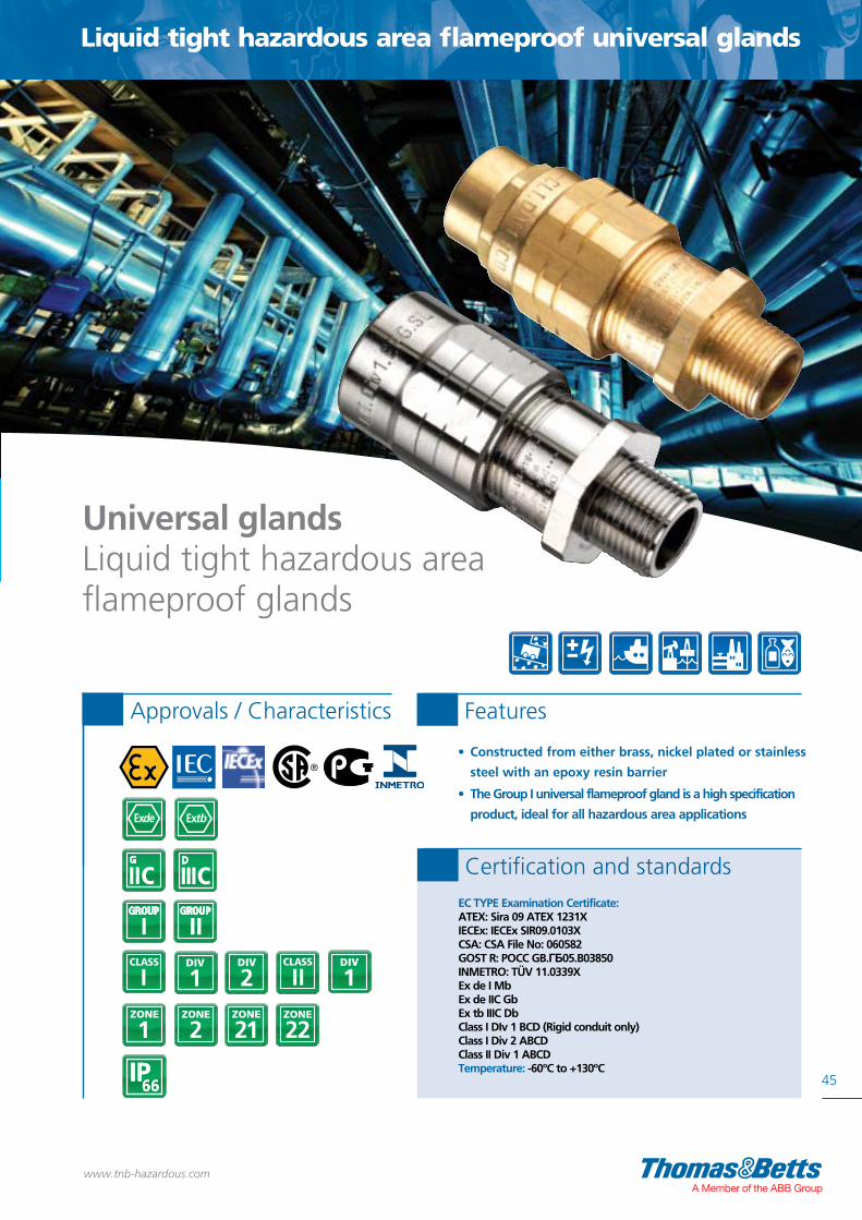
45
Liquid tight hazardous area flameproof universal glands
www.tnb-hazardous.comA Member of the ABB Group
• Constructed from either brass, nickel plated or stainless
steel with an epoxy resin barrier
• The Group I universal flameproof gland is a high specification
product, ideal for all hazardous area applications
Approvals / Characteristics Features
Universal glands Liquid tight hazardous area flameproof glands
EC TYPE Examination Certificate:ATEX: Sira 09 ATEX 1231XIECEx: IECEx SIR09.0103XCSA: CSA File No: 060582GOST R: POCC GB.ГБ05.B03850INMETRO: TÜV 11.0339XEx de I MbEx de IIC GbEx tb IIIC DbClass I DIv 1 BCD (Rigid conduit only)Class I Div 2 ABCDClass II Div 1 ABCDTemperature: -60ºC to +130ºC
Certification and standards
1DIV
2DIV
I 1DIV

Nickel Plated Male Thread Size Female Thread SizeType - NPT NPT (inch) NPT (inch)
HAAM0304U 1/2 3/8
HAAM0404U 1/2 1/2
HAAM0505U 3/4 3/4
HAAM0606U 1 1
HAAM0707U 11/4 11/4
HAAM0808U 11/2 11/2
HAAM0909U 2 2
Nickel Plated Male Thread Size Female Thread SizeType - Metric Metric (mm) Metric (mm)
HAMM0304U 20 16
HAMM0404U 20 20
HAMM0505U 25 25
HAMM0606U 32 32
HAMM0707U 40 40
HAMM0808U 50 50
HAMM0909U 63 63
46
HAA 03 04 U
HAM 03 04 U
Thread B = 1/2” NPTThread A = 3/8” NPT
HAA 03 04 U
HAM 03 04 U
THREAD B THREAD A
HAA 03 04 U
HAM 03 04 U
THREAD B THREAD A
HAA 03 04 U
HAM 03 04 U
Thread A = M16 Thread B = M20
Dimensions
Universal gland
www.tnb-hazardous.com
Brass Male Thread Size Female Thread SizeType - NPT NPT (inch) NPT (inch)
HAA0304U 1/2 3/8
HAA0404U 1/2 1/2
HAA0505U 3/4 3/4
HAA0606U 1 1
HAA0707U 11/4 11/4
HAA0808U 11/2 11/2
HAA0909U 2 2
Brass Male Thread Size Female Thread SizeType - Metric Metric (mm) Metric (mm)
HAM0304U 20 16
HAM0404U 20 20
HAM0505U 25 25
HAM0606U 32 32
HAM0707U 40 40
HAM0808U 50 50
HAM0909U 63 63
Stainless Steel Male Thread Size Female Thread SizeType - Metric Metric (mm) Metric (mm)
HAMS0304U 20 16
HAMS0404U 20 20
HAMS0505U 25 25
HAMS0606U 32 32
HAMS0707U 40 40
HAMS0808U 50 50
HAMS0909U 63 63
Stainless Steel Male Thread Size Female Thread SizeType - NPT NPT (inch) NPT (inch)
HAAS0304U 1/2 3/8
HAAS0404U 1/2 1/2
HAAS0505U 3/4 3/4
HAAS0606U 1 1
HAAS0707U 11/4 11/4
HAAS0808U 11/2 11/2
HAAS0909U 2 2
Technical specifications
Liquid tight hazardous area flameproof universal glands
For use with rigid conduit or other fittings

HAA 03 04 U/SW
HAM 03 04 U/SW
47
www.tnb-hazardous.comA Member of the ABB Group
Nickel Plated Male Thread Size Female Thread SizeType - Metric Metric (mm) Metric (mm)
HAMM0304U/SW 20 16
HAMM0404U/SW 20 20
HAMM0505U/SW 25 25
HAMM0606U/SW 32 32
HAMM0707U/SW 40 40
HAMM0808U/SW 50 50
HAMM0909U/SW 63 63
Nickel Plated Male Thread Size Female Thread SizeType - NPT NPT (inch) NPT (inch)
HAAM0304U/SW 1/2 3/8
HAAM0404U/SW 1/2 1/2
HAAM0505U/SW 3/4 3/4
HAAM0606U/SW 1 1
HAAM0707U/SW 11/4 11/4
HAAM0808U/SW 11/2 11/2
HAAM0909U/SW 2 2
Liquid tight hazardous area flameproof universal glands
Thread B = 1/2” NPTThread A = 3/8” NPT
HAA 03 04 U
HAM 03 04 U
THREAD B THREAD A
HAA 03 04 U
HAM 03 04 U
THREAD B THREAD A
HAA 03 04 U/SW
HAM 03 04 U/SW
Thread A = M16 Thread B = M20
Technical specificationsDimensions
Universal swivel gland
Related products
For accessories see pages 134-35
Sealing 135washers
Brass Male Thread Size Female Thread SizeType - Metric Metric (mm) Metric (mm)
HAM0304U/SW 20 16
HAM0404U/SW 20 20
HAM0505U/SW 25 25
HAM0606U/SW 32 32
HAM0707U/SW 40 40
HAM0808U/SW 50 50
HAM0909U/SW 63 63
Brass Male Thread Size Female Thread SizeType - NPT NPT (inch) NPT (inch)
HAA0304U/SW 1/2 3/8
HAA0404U/SW 1/2 1/2
HAA0505U/SW 3/4 3/4
HAA0606U/SW 1 1
HAA0707U/SW 11/4 11/4
HAA0808U/SW 11/2 11/2
HAA0909U/SW 2 2
For use with rigid conduit or other fittings

• UL listed for use in hazardous and wet locations
• Corrosion-resistant - ideal for washdown areas
• Flexible bronze construction with arc-resistant inner
sleeve and brass fittings
• Terminated with two threaded female end fittings
and male close nipples
• No bonding jumper required
48
1DIV
2DIV
I
1DIV
Approvals / Characteristics Features
XP Flex™ rangeExplosion-proof flexible couplings
UL listed:0.5” and 0.75” hub sizes: Class I Div 1 & 2 ABCD; Class II Div 1 EFG, Class III1” hub size: Class I Div 1 & 2 CD; Class II Div 1 EFG, Class IIIUL listed 886
Certification and standards
www.tnb-hazardous.com

Explosion-proof flexible couplings - XP Flex™ range
Dimensions (mm)Type Thread Type (inch) Flexible Length (mm) A B
XPLFL16 1/2” NPT 150 39.1 36.6
XPLFL18 1/2” NPT 200 39.1 36.6
XPLFL110 1/2” NPT 250 39.1 36.6
XPLFL112 1/2” NPT 300 39.1 36.6
XPLFL115 1/2” NPT 380 39.1 36.6
XPLFL118 1/2” NPT 460 39.1 36.6
XPLFL124 1/2” NPT 610 39.1 36.6
XPLFL212 3/4” NPT 300 40.6 47.5
XPLFL215 3/4” NPT 380 40.6 47.5
XPLFL218 3/4” NPT 460 40.6 47.5
XPLFL224 3/4” NPT 610 40.6 47.5
XPLFL236 3/4” NPT 915 40.6 47.5
XPLFL318 1” NPT 460 50.08 58.7
49
Explosion-proof and dust-ignition-proof for use in hazardous locationsWith their flexible design, T&B® XP FlexTM couplings make it easy to achieve tight bends in conduit systems in confined spaces - or to connect stationary equipment to equipment that moves or vibrates. Their explosion-proof and corrosion-resistant construction mean you can use them with confidence in hazardous and wet locations.
Technical specificationsDimensions
NPTThreads
FlexibleLength
AB
NPTThreads
FlexibleLength
AB
Enlargers, reducers and thread convertors 128
Sealing 135washers
Related products
Locknuts 134
www.tnb-hazardous.comA Member of the ABB Group

2650
www.tnb-hazardous.com
Kopex-Ex cable glands

Kopex-Ex cable glands
51
www.tnb-hazardous.comA Member of the ABB Group

52
Cable glands, thread convertors, stopping plugs and accessories - selection guide
www.tnb-hazardous.com
Ex d, Ex e Cable glands
Unarmoured cable glands Page 58
Flameproof armoured cable glands Page 62
Flameproof unarmoured cable glands Page 60
Nylon cableglands Page 64
Armoured cable blands Page 54
Ex d cable glands Page 56
Prot
ectio
n Ty
peG
asG
roup
Dus
tG
roup
Zo
nes
1DIV
2DIVI
2DIV
1DIV

Cable glands, thread convertors, stopping plugs and accessories - selection guide
53
Cable glands, thread convertors, stopping plugs and accessories - selection guide
www.tnb-hazardous.comA Member of the ABB Group
Accessories
Sealing joint washer Page 135
Earth tag Page 135
Serrated washer Page 135
Nickel plated coupler Page 134
Hex locknut Page 134
Standard stopping plugs Page 130
Tamperproofstopping plugs Page 130
Hex headstoppingplugs Page 132
Thread convertors Page 128
Nylon stoppingplugs Page 132
Dome headstopping plugs Page 132
Thread convertors and stopping plugs

• Suitable for use with – SWA (Steel wired Armoured) – AWB (Aluminium wired Braid) – AWA (Aluminium wired Armoured)• Flameproof Ex d and increased safety Ex e• Available in brass, nickel plated brass and stainless steel 316• Deluge proof• Wide range of cable sizes
Approvals / Characteristics Features
54
www.tnb-hazardous.com
Approved to: EN60079-0, 60079-1, 60079-7, 60079-31EC TYPE Examination Certificate:CESI 13 ATEX 041X, IECEx CES 13.0014XEx d IIC GbEx e IIC GbEx tb IIIC DbIP66-68 - 5-Bar 30 minsTemperature: -40°C to +100°C
Certification and standards
C1 SeriesEx d double compression cable gland
4 function double compression cable gland
8
NEW

55
Technical specificationsDimensions
Brass Metric Sealing Range Cable Gland Dimensions Torque (Nm)Part No. Thread D (min-max) D1 (min-max) H Min L Min CH1 CH2 CH3 D2 Min CH2 CH3
EX03MSC1 M16 3 - 8.5 6 - 12 47 16 22 26 26 29 27.0 25.0
EX03MMC1 M16 6 - 12 8.5 - 16 48 16 25 29 29 31.5 49.0 28.0
EX04MSC1 M20 3 - 8.5 6 - 12 47 16 24 26 26 29 27.0 25.0
EX04MMC1 M20 6 - 12 8.5 - 16 47 16 25 29 29 31.5 49.0 28.0
EX04MLC1 M20 12 - 14.5 16 - 20 50 16 28 30 32 35 33.0 33.0
EX05MSC1 M25 6 - 12 8.5 - 16 48 18 29 29 29 31.5 49.0 28.0
EX05MMC1 M25 12 - 16 16 - 21 53 18 32 34 34 37 30.0 27.0
EX05MLC1 M25 12 - 20 16 - 26 60 18 36 40 40 44 61.0 32.0
EX06MSC1 M32 12 - 20 16 - 26 62 18 40 40 40 44 61.0 32.0
EX06MMC1 M32 15 - 26 20 - 33 78 18 48 52 52 57 86.0 40.0
EX07MSC1 M40 15 - 26 20 - 33 78 18 48 52 52 57 86.0 40.0
EX07MMC1 M40 20 - 32 29 - 41 89 18 55 60 60 66 110.0 75.0
EX08MSC1 M50 22 - 35 33 - 48 97 18 60 70 75 82 110.0 75.0
EX08MMC1 M50 27 - 41 36 - 52 100 18 70 70 74 83 125.0 75.0
EX09MSC1 M63 35 - 45 43 - 57 106 20 75 80 80 89.5 160.0 140.0
EX09MMC1 M63 40 - 52 47 - 60 107 20 85 85 85 94 250.0 100.0
EX10MSC1 M75 40 - 52 47 - 60 107 20 85 85 85 94 250.0 100.0
EX10MMC1 M75 45 - 60 54 - 70 125 20 90 95 100 110.5 250.0 150.0
EX11MSC1 M90 45 - 60 54 - 70 125 20 95 95 100 110.5 250.0 150.0
EX11MMC1 M90 60 - 72 63 - 80 154 20 110 115 115 127 320.0 210.0
Brass Metric Brass NPT
PositionMarking
D1 D2Size D
CH3CH2CH1HL
1 3 2 3 4 5 3 6 7 8
1. Lower Body2. Lower Sealing Ring3. O-Ring4. Grounding Cone5. Swivel Braid Retainer6. Middle Body7. Upper Sealing Ring8. Pressure Cap
PositionMarking
D1 D2Size D
CH3CH2CH1HL
1 2 3 4 5 3 6 7 8
1. Lower Body2. Lower Sealing Ring3. O-Ring4. Grounding Cone5. Swivel Braid Retainer6. Middle Body7. Upper Sealing Ring8. Pressure Cap
www.tnb-hazardous.comA Member of the ABB Group
Brass NPT Sealing Range Cable Gland Dimensions Torque (Nm)Part No. Thread D (min-max) D1 (min-max) H Min L Min CH1 CH2 CH3 D2 Min CH2 CH3
EX03ASC1 3/8” 3 - 8,5 6 - 12 47 16 22 26 26 29 27.0 25.0
EX03AMC1 3/8” 6 - 12 8.5 - 16 48 16 25 29 29 31.5 49.0 28.0
EX04ASC1 1/2” 3 - 8.5 6 - 12 47 21 24 26 26 29 27.0 25.0
EX04AMC1 1/2” 6 - 12 8.5 - 16 47 21 25 29 29 31.5 49.0 28.0
EX04ALC1 1/2” 12 - 14.5 16 - 20 50 21 28 30 32 35 33.0 33.0
EX05ASC1 3/4” 6 - 12 8.5 - 16 48 21 29 29 29 31.5 49.0 28.0
EX05AMC1 3/4” 12 - 16 16 - 21 53 21 32 34 34 37 30.0 27.0
EX05ALC1 3/4” 12 - 20 16 - 26 60 21 36 40 40 44 61.0 32.0
EX06ASC1 1” 12 - 20 16 - 26 62 26 40 40 40 44 61.0 32.0
EX06AMC1 1” 15 - 26 20 - 33 78 26 48 52 52 57 86.0 40.0
EX07ASC1 1 1/4” 15 - 26 20 - 33 78 28 48 52 52 57 86.0 40.0
EX07AMC1 1 1/4” 20 - 32 29 - 41 89 28 55 60 60 66 110.0 75.0
EX08ASC1 1 1/2” 22 - 35 33 - 48 97 28 60 70 75 82 110.0 75.0
EX08AMC1 1 1/2” 27 - 41 36 - 52 100 28 70 70 74 83 125.0 75.0
EX09ASC1 2” 35 - 45 43 - 57 106 28 75 80 80 89.5 160.0 140.0
EX09AMC1 2” 40 - 52 47 - 60 107 28 85 85 85 94 250.0 100.0
EX10ASC1 2 1/2” 40 - 52 47 - 60 107 41 85 85 85 94 250.0 100.0
EX10AMC1 2 1/2” 45 - 60 54 - 70 125 41 90 95 100 110.5 250.0 150.0
EX11ASC1 3” 45 - 60 54 - 70 125 43 95 95 100 110.5 250.0 150.0
EX11AMC1 3” 60 - 72 63 - 80 154 43 110 115 115 127 320.0 210.0
*For nickel plated brass version, add N to the reference, e.g. EXN03MSC1 for Metric / EXN03ASC1 for NPT **For stainless steel 316 version, add S to the reference, e.g. EXS03MSC1 for Metric / EXS03ASC1 for NPT ***To purchase cable glands with locknuts, shrouds, earth tags, and washers where appropriate add a K to the end of the part number e.g EX04MMC1K
Ex d double compression cable gland - C1 Series

Approvals / Characteristics Features
56
www.tnb-hazardous.com
C2 SeriesEx e/Ex d cable gland
Single compression cable gland
• Suitable for use with unarmoured cable• Flameproof Ex e and Ex d• Available in brass, nickel plated brass and stainless steel 316 • Large cable range within one product with removeable seals
Approved to: EN/IEC 60079-0, EN 60079-1, EN 60079-7,EN 60079-11, EN 60079-31 EC TYPE Examination Certificate:IMQ 13 ATEX 015XII 2GD / Exe IIC GbEx tb IIIC Db IP66-68 - 5-Bar 30 mins Temperature: -40°C to +100°C
Certification and standards
8
NEW

57
Technical specificationsDimensions
Position Marking
1. Sealing Ring2. Cap3. Body
H
S1
S2
S3
P
P = Sealing Combination
Size
L1
L1
2
3
www.tnb-hazardous.comA Member of the ABB Group
Brass Metric Cable Gland Dimensions Sealing Ring DimensionsPart No. Thread L L Min CH H Min Min-Max S3 S2 S1 Torque (Nm)
EX03MMC2 M16 40 16 22 20 3 - 12 3 - 6 6 - 9 9 - 12 19
EX04MMC2 M20 40 16 22 20 3 - 12 3 - 6 6 - 9 9 - 12 19
EX04MLC2 M20 45 16 28 20 10 - 16 – 10 - 14 14 - 16 28
EX05MMC2 M25 40 16 28 20 10 - 18 – 10 - 14 14 - 18 28
EX05MLC2 M25 50 16 35 25 14 - 20 – 14 - 17 17 - 20 31
EX06MMC2 M32 43 16 35 25 14 - 24 14 - 17 17 - 20 20 - 24 31
EX06MLC2 M32 53 16 45 39 22 - 28 – 22 - 26 26 - 28 26
EX07MMC2 M40 45 18 45 39 22 - 32 – 22 - 26 26 - 32 26
EX07MLC2 M40 55 18 50 32 26 - 34 – 26 - 32 32 - 34 58
EX08MMC2 M50 46 18 55 / 50 32 26 -35 – 26 - 30 30 - 35 58
EX08MLC2 M50 63 18 55 / 58 38 35 - 42 – 35 - 38 38 - 42 60
EX09MMC2 M63 53 18 68 / 58 38 35 - 45 – 35 - 38 38 - 45 60
EX09MLC2 M63 62 18 75 / 80 25 46 - 56 – 46 - 51 51 - 56 75
EX10MMC2 M75 64 20 80 25 46 - 62 46 - 51 51 - 57 57 - 62 75
EX10MLC2 M75 75 20 95 36 60 - 69 – 60 - 63 63 - 69 110
EX11MMC2 M90 75 20 95 36 60 - 75 60 - 63 63 - 69 69 - 75 110
EX11MLC2 M90 77 20 105 38 75 - 82 – 75 - 79 79 - 82 130
EX12MMC2 M100 77 20 115 / 105 38 75 - 85 75 - 79 79 - 82 82 - 85 130
EX12MMC2 M110 77 20 115 38 85 - 95 85 - 89 89 - 92 92 - 95 140
Brass NPT Cable Gland Dimensions Sealing Ring DimensionsPart No. Thread L L Min CH H Min Min-Max S3 S2 S1 Torque (Nm)
EX03AMC2 3/8” 40 16 22 20 3 - 12 3 - 6 6 - 9 9 - 12 19
EX04AMC2 1/2” 40 16 22 20 3 - 12 3 - 6 6 - 9 9 - 12 19
EX04ALC2 1/2” 45 16 28 20 10 - 16 – 10 - 14 14 - 16 28
EX05AMC2 3/4” 40 16 28 20 10 - 18 – 10 - 14 14 - 18 28
EX05ALC2 3/4” 50 16 35 25 14 - 20 – 14 - 17 17 - 20 31
EX06AMC2 1” 47 20 35 25 14 - 24 14 - 17 17 - 20 20 - 24 31
EX06ALC2 1” 57 20 45 39 22 - 28 – 22 - 26 26 - 28 26
EX07AMC2 1 1/4” 47 20 45 39 22 - 32 – 22 - 26 26 - 32 26
EX07ALC2 1 1/4” 57 20 50 32 26 - 34 – 26 - 32 32 - 34 58
EX08AMC2 1 1/2” 48 20 55 / 50 32 26 -35 – 26 - 30 30 - 35 58
EX08ALC2 1 1/2” 65 20 55 / 58 38 35 - 42 – 35 - 38 38 - 42 60
EX09AMC2 2” 55 20 68 / 58 38 35 - 45 – 35 - 38 38 - 45 60
EX09ALC2 2” 64 20 75 / 80 25 46 - 56 – 46 - 51 51 - 56 75
EX10AMC2 2 1/2” 70 26 80 25 46 - 62 46 - 51 51 - 57 57 - 62 75
EX10ALC2 2 1/2” 81 26 95 36 60 - 69 – 60 - 63 63 - 69 110
EX11AMC2 3” 81 26 95 36 60 - 75 60 - 63 63 - 69 69 - 75 110
EX11ALC2 3” 83 26 105 38 75 - 82 – 75 - 79 79 - 82 130
EX12AMC2 4” 83 26 115 / 105 38 75 - 85 75 - 79 79 - 82 82 - 85 130
EX12AMC2 4” 83 26 115 38 85 - 95 85 - 89 89 - 92 92 - 95 140
*For nickel plated brass version, add N to the reference, e.g. EXN03MMC2 for Metric / EXN03AMC2 for NPT ***To purchase cable glands with locknuts, shrouds, earth tags, and washers where appropriate add a K to the end of the part number e.g EX04MMC1K
Ex e / Ex d cable gland - C2 Series
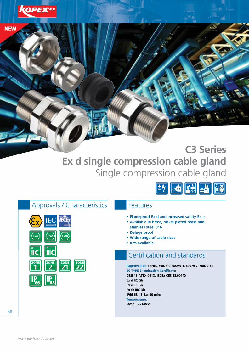
• Flameproof Ex d and increased safety Ex e• Available in brass, nickel plated brass and stainless steel 316• Deluge proof• Wide range of cable sizes• Kits available
Approvals / Characteristics Features
58
www.tnb-hazardous.com
Approved to: EN/IEC 60079-0, 60079-1, 60079-7, 60079-31EC TYPE Examination Certificate:CESI 13 ATEX 041X, IECEx CES 13.0014XEx d IIC GbEx e IIC GbEx tb IIIC DbIP66-68 - 5-Bar 30 minsTemperature: -40°C to +100°C
Certification and standards
C3 SeriesEx d single compression cable gland
Single compression cable gland
8
NEW
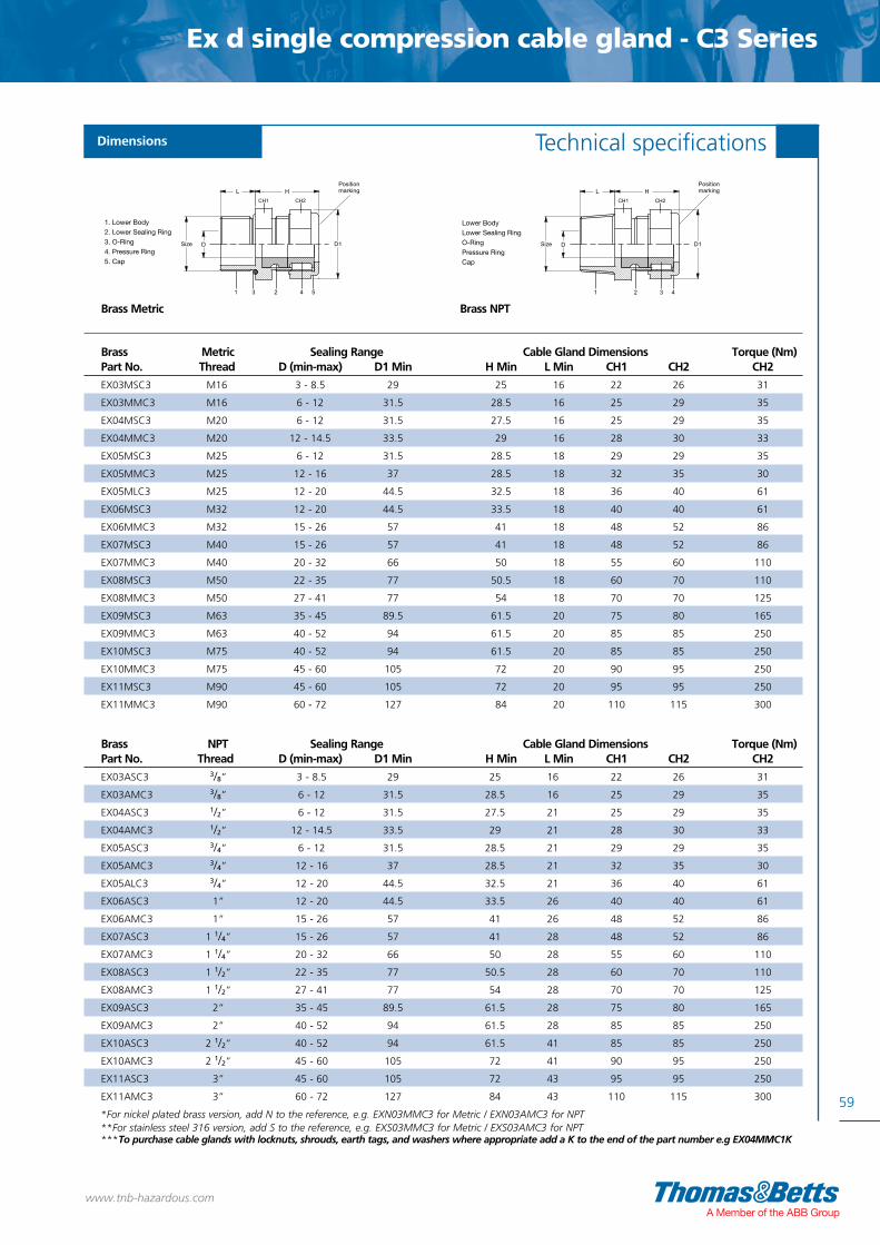
Brass NPT Sealing Range Cable Gland Dimensions Torque (Nm)Part No. Thread D (min-max) D1 Min H Min L Min CH1 CH2 CH2
EX03ASC3 3/8” 3 - 8.5 29 25 16 22 26 31
EX03AMC3 3/8” 6 - 12 31.5 28.5 16 25 29 35
EX04ASC3 1/2” 6 - 12 31.5 27.5 21 25 29 35
EX04AMC3 1/2” 12 - 14.5 33.5 29 21 28 30 33
EX05ASC3 3/4” 6 - 12 31.5 28.5 21 29 29 35
EX05AMC3 3/4” 12 - 16 37 28.5 21 32 35 30
EX05ALC3 3/4” 12 - 20 44.5 32.5 21 36 40 61
EX06ASC3 1” 12 - 20 44.5 33.5 26 40 40 61
EX06AMC3 1” 15 - 26 57 41 26 48 52 86
EX07ASC3 1 1/4” 15 - 26 57 41 28 48 52 86
EX07AMC3 1 1/4” 20 - 32 66 50 28 55 60 110
EX08ASC3 1 1/2” 22 - 35 77 50.5 28 60 70 110
EX08AMC3 1 1/2” 27 - 41 77 54 28 70 70 125
EX09ASC3 2” 35 - 45 89.5 61.5 28 75 80 165
EX09AMC3 2” 40 - 52 94 61.5 28 85 85 250
EX10ASC3 2 1/2” 40 - 52 94 61.5 41 85 85 250
EX10AMC3 2 1/2” 45 - 60 105 72 41 90 95 250
EX11ASC3 3” 45 - 60 105 72 43 95 95 250
EX11AMC3 3” 60 - 72 127 84 43 110 115 300
*For nickel plated brass version, add N to the reference, e.g. EXN03MMC3 for Metric / EXN03AMC3 for NPT **For stainless steel 316 version, add S to the reference, e.g. EXS03MMC3 for Metric / EXS03AMC3 for NPT ***To purchase cable glands with locknuts, shrouds, earth tags, and washers where appropriate add a K to the end of the part number e.g EX04MMC1K
59
Technical specificationsDimensions
H
Size D D1
1 23
CH1
L
4 5
Positionmarking
CH2
1. Lower Body2. Lower Sealing Ring3. O-Ring4. Pressure Ring5. Cap
H
2
Size D D1
1
CH1
L
43
CH2
Positionmarking
1. Lower Body2. Lower Sealing Ring3. O-Ring4. Pressure Ring5. Cap
Brass Metric Sealing Range Cable Gland Dimensions Torque (Nm)Part No. Thread D (min-max) D1 Min H Min L Min CH1 CH2 CH2
EX03MSC3 M16 3 - 8.5 29 25 16 22 26 31
EX03MMC3 M16 6 - 12 31.5 28.5 16 25 29 35
EX04MSC3 M20 6 - 12 31.5 27.5 16 25 29 35
EX04MMC3 M20 12 - 14.5 33.5 29 16 28 30 33
EX05MSC3 M25 6 - 12 31.5 28.5 18 29 29 35
EX05MMC3 M25 12 - 16 37 28.5 18 32 35 30
EX05MLC3 M25 12 - 20 44.5 32.5 18 36 40 61
EX06MSC3 M32 12 - 20 44.5 33.5 18 40 40 61
EX06MMC3 M32 15 - 26 57 41 18 48 52 86
EX07MSC3 M40 15 - 26 57 41 18 48 52 86
EX07MMC3 M40 20 - 32 66 50 18 55 60 110
EX08MSC3 M50 22 - 35 77 50.5 18 60 70 110
EX08MMC3 M50 27 - 41 77 54 18 70 70 125
EX09MSC3 M63 35 - 45 89.5 61.5 20 75 80 165
EX09MMC3 M63 40 - 52 94 61.5 20 85 85 250
EX10MSC3 M75 40 - 52 94 61.5 20 85 85 250
EX10MMC3 M75 45 - 60 105 72 20 90 95 250
EX11MSC3 M90 45 - 60 105 72 20 95 95 250
EX11MMC3 M90 60 - 72 127 84 20 110 115 300
Brass Metric Brass NPT
www.tnb-hazardous.comA Member of the ABB Group
Ex d single compression cable gland - C3 Series

• A compound barrier cable gland for use with unarmoured cable• Suitable for use in Zones 1, 2, 21, 22• Flameproof Ex d and increased safety Ex e• Available in brass, nickel plated brass and stainless steel 316• Deluge proof• Wide range of cable sizes
Approvals / Characteristics Features
60
www.tnb-hazardous.com
Approved to: EN/IEC 60079-0, 60079-1, 60079-7, 60079-31EC TYPE Examination Certificate:CESI 13 ATEX 041X, IECEx CES 13.0014XEx d IIC GbEx e IIC GbEx tb IIIC DbIP66Temperature: -40°C to +100°C
Certification and standards
8
NEW
C4 SeriesEx d flameproof cable gland
Unarmoured cable compound barrier gland

61
Technical specificationsDimensions
Brass NPT
ØD2
TD
TL H
ØD1
SW3
SW1
SW2
ØD
1 2 3 4 2 5 6 78
ØD2
TD
TL H
ØD1
SW3
SW1
SW2
ØD
1 2 3 4 2 5 6 7
www.tnb-hazardous.comA Member of the ABB Group
Ex d flameproof cable gland - C4 Series
Brass Metric
1. Body2. O-Ring3. Pot4. Pressurising Bushing
1. Body2. O-Ring3. Pot4. Pressurising Bushing
5. Upper Body6. Upper Sealing Ring7. Cap8. Washer
5. Upper Body6. Upper Sealing Ring7. Cap
Brass Metric Cable Gland Dimensions (mm) Cable diameter range Torque (Nm)Part No. Thread H TL ØD ØD1 ØD2 SW1 SW2 SW3 min-max (mm) SW2 SW3
EX04MC4 M20 62 16 33 16.5 14 30 30 30 8.5-16.0 30.0 28.0
EX05MC4 M25 62.8 16 37 21.5 18.5 34 34 34 16.0-21.0 45.0 27.0
EX06MC4 M32 68.5 16 45 26.5 25.6 42 42 40 16.0-26.0 65.0 32.0
EX07MC4 M40 75.1 16 66 41.5 33 50 60 60 29.0-41.0 75.0 75.0
EX08MC4 M50 82.7 16 77 48.5 43 60 70 75 33.0-48.0 90.0 75.0
EX09MC4 M63 96 16 77 52.5 52 70 70 74 36.0-52.0 100.0 75.0
Brass NPT Cable Gland Dimensions (mm) Cable diameter range Torque (Nm)Part No. Thread H TL ØD ØD1 ØD2 SW1 SW2 SW3 min-max (mm) SW2 SW3
EX04AC4 1/2” 62 21 33 16.5 14 30 30 30 8.5-16.0 30.0 28.0
EX05AC4 3/4” 62.8 21 37 21.5 18.5 34 34 34 16.0-21.0 45.0 27.0
EX06AC4 1” 68.5 26 45 26.5 25.6 42 42 40 16.0-26.0 65.0 32.0
EX07AC4 1 1/4” 75.1 28 66 41.5 33 50 60 60 29.0-41.0 75.0 75.0
EX08AC4 1 1/2” 82.7 28 77 48.5 43 60 70 75 33.0-48.0 90.0 75.0
EX09AC4 2” 96 28 77 52.5 52 70 70 74 36.0-52.0 100.0 75.0
*For nickel plated brass version, add N to the reference, e.g. EXN04MC4 for Metric / EXS04AC4 for NPT **For stainless steel 316 version, add S to the reference, e.g. EXS04MC4 for Metric / EXS04AC4 for NPT

• A compound barrier cable gland for use with – SWA (Steel wired Armoured) – SWB (Steel wired Braid) – AWA (Aluminium wired Armoured)• Suitable for use in Zones 1, 2, 21, 22• Flameproof Ex d and increased safety Ex e• Available in brass, nickel plated brass and stainless steel 316• Deluge proof• Wide range of cable sizes
Approvals / Characteristics Features
62
www.tnb-hazardous.com
Approved to: EN/IEC 60079-0, 60079-1, 60079-7, 60079-31EC TYPE Examination Certificate:CESI 13 ATEX 041X, IECEx CES 13.0014XEx d IIC GbEx e IIC GbEx tb IIIC DbIP66Temperature: -40°C to +100°C
Certification and standards 8
NEW
C5 SeriesEx d flameproof cable gland
Armoured cable compound barrier gland

63
Technical specificationsDimensions
SW3
SW1
SW2
ØD1
ØD2
TD
TL H
ØD
1 2 3 4 2 5 6 7 8 9 1011
SW3
SW1
SW2
ØD1
ØD2
TD
TL H
ØD
1 2 3 4 2 5 6 7 8 9 10
www.tnb-hazardous.comA Member of the ABB Group
Ex d flameproof cable gland - C5 Series
Brass Metric Cable Gland Dimensions (mm) Cable diameter range Torque (Nm)Part No. Thread H TL ØD ØD1 ØD2 SW1 SW2 SW3 min-max (mm) SW2 SW3
EX04MC5 M20 70 16 33 16.5 14 30 30 29 8.5-16.0 30.0 28.0
EX05MC5 M25 72.1 16 37 21.5 15.5 34 34 34 16.0-21.0 45.0 27.0
EX06MC5 M32 76 16 45 26.5 25.6 42 42 40 16.0-26.0 65.0 32.0
EX07MC5 M40 83.4 16 66 41.5 33 50 60 60 29.0-41.0 75.0 75.0
EX08MC5 M50 96.6 16 77 48.5 43 60 70 75 33.0-48.0 90.0 75.0
EX09MC5 M63 109.5 16 77 52.5 52 70 70 74 36.0-52.0 100.0 75.0
Brass NPT Cable Gland Dimensions (mm) Cable diameter range Torque (Nm)Part No. Thread H TL ØD ØD1 ØD2 SW1 SW2 SW3 min-max (mm) SW2 SW3
EX04AC5 1/2” 70 21 33 16.5 14 30 30 30 8.5-16.0 30.0 28.0
EX05AC5 3/4” 72.1 21 37 21.5 15.5 34 34 34 16.0-21.0 45.0 27.0
EX06AC5 1” 76 26 45 26.5 25.6 42 42 40 16.0-26.0 65.0 32.0
EX07AC5 1 1/4” 83.4 28 66 41.5 33 50 60 60 29.0-41.0 75.0 75.0
EX08AC5 1 1/2” 96.6 28 77 48.5 43 60 70 75 33.0-48.0 90.0 75.0
EX09AC5 2” 109.5 28 77 52.5 52 70 70 74 36.0-52.0 100.0 75.0
*For nickel plated brass version, add N to the reference, e.g. EXN04MC5 for Metric / EXS04AC5 for NPT **For stainless steel 316 version, add S to the reference, e.g. EXS04MC5 for Metric / EXS04AC5 for NPT
Brass Metric Brass NPT
1. Body2. O-Ring3. Pot4. Gounding Cone5. Armour Reduction6. Swivel Braid Ring
1. Body2. O-Ring3. Pot4. Gounding Cone5. Armour Reduction
17. O-Ring18. Upper Body19. Upper Sealing Ring10. Cap11. Washer
16. Swivel Braid Ring 17. O-Ring18. Upper Body19. Upper Sealing Ring10. Cap

Approvals / Characteristics Features
64
www.tnb-hazardous.com
Nylon cable gland
Ex e nylon cable gland
• Suitable for potentially explosive gas atmospheres
• Increased safety “e” and intrinsic safety “i”
Approved to: EN/IEC 60079-0, 60079-7, 60079-11, 60079-31 EC TYPE Examination Certificate:IMQ 13 ATEX 016X, IECEx IMQ 13.0005XEx e IIC GbEx tb IIIC Db IP test: IP66-IP68 Temperature: -40°C to +80°C
Certification and standards
b
8
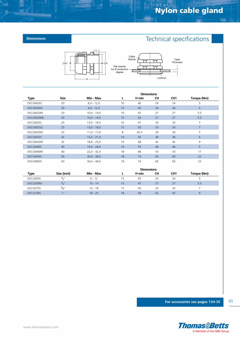
Nylon cable gland
65
Technical specificationsDimensions
For accessories see pages 134-35
Dimensions Type Size Min - Max L H min CH CH1 Torque (Nm)
EXCGM20S 20 6,0 - 12,0 10 40 24 24 5
EXCGM20SL 20 6,0 - 12,0 15 45 24 24 5
EXCGM20M 20 10,0 - 14,0 10 42 27 27 5.5
EXCGM20ML 20 10,0 - 14,0 15 50 27 27 5.5
EXCGM25S 25 13,0 - 18,0 10 47 33 33 7
EXCGM25SL 25 13,0 - 18,0 15 50 33 33 7
EXCGM25M 25 11,0 - 17,0 8 42.5 29 29 5
EXCGM32S 32 15,0 - 21,0 10 50 36 36 6
EXCGM32M 32 18,0 - 25,0 15 68 42 42 9
EXCGM40S 40 19,0 - 28,0 10 55 46 46 5
EXCGM40M 40 22,0 - 32,0 18 68 53 53 17
EXCGM50S 50 30,0 - 38,0 18 73 60 60 22
EXCGM63S 63 34,0 - 44,0 18 74 65 65 23
Locknut
CaseThickness
CableGlands
Flat washerfor IP protection
degree
H
CH1 R
L
M CH
www.tnb-hazardous.comA Member of the ABB Group
Dimensions Type Size (inch) Min - Max L H min CH CH1 Torque (Nm)
EXCG050S 1/2” 6 - 12 15 45 24 24 5
EXCG050M 1/2” 10 - 14 15 47 27 27 5.5
EXCG075S 3/4” 13 - 18 15 50 33 33 7
EXCG100S 1” 18 - 25 18 58 42 42 9

2666
www.tnb-hazardous.com
Star Teck® cable glands
26266626

Star Teck® Cable Glands
67
www.tnb-hazardous.comA Member of the ABB Group

68
Star Teck® cable glands - selection guide
www.tnb-hazardous.com
Star Teck XP® (STX) series Page 76
Star Teck Extreme DirectorTM (STED) series Page 82
Iberville® Tek Page 86
Iberville® TCAX TM Page 88
Star Teck® ST series Page 74
023086
AEX
023086
Exe II
E, F & G
E, F & G
Type 4, 4x
023086
E82038
A, B, C & D
A, B, C & D
E, F & G
E, F & G
Type 4x, 6P
023086
AEX
023086
Exe II
E, F & G
E, F & G
Type 6P
023086
E82038 E82038
A, B, C & D
A, B, C & D A, B, C & D
E, F & G E, F & G
E, F & G
Type 4x, 6P
023086 051586 051586
AEX
023086
E, F & G A, B, C & D A, B, C & D
E, F & G E, F & G E, F & G
Type 6P Type 4, 4x Type 4, 4x
1DIV
2DIV
Star Teck Extreme® (STE) series Page 78
Star Teck Extreme XP® (STEX) series Page 80
I
I
I

Star Teck® cable glands - selection guide
69
www.tnb-hazardous.comA Member of the ABB Group
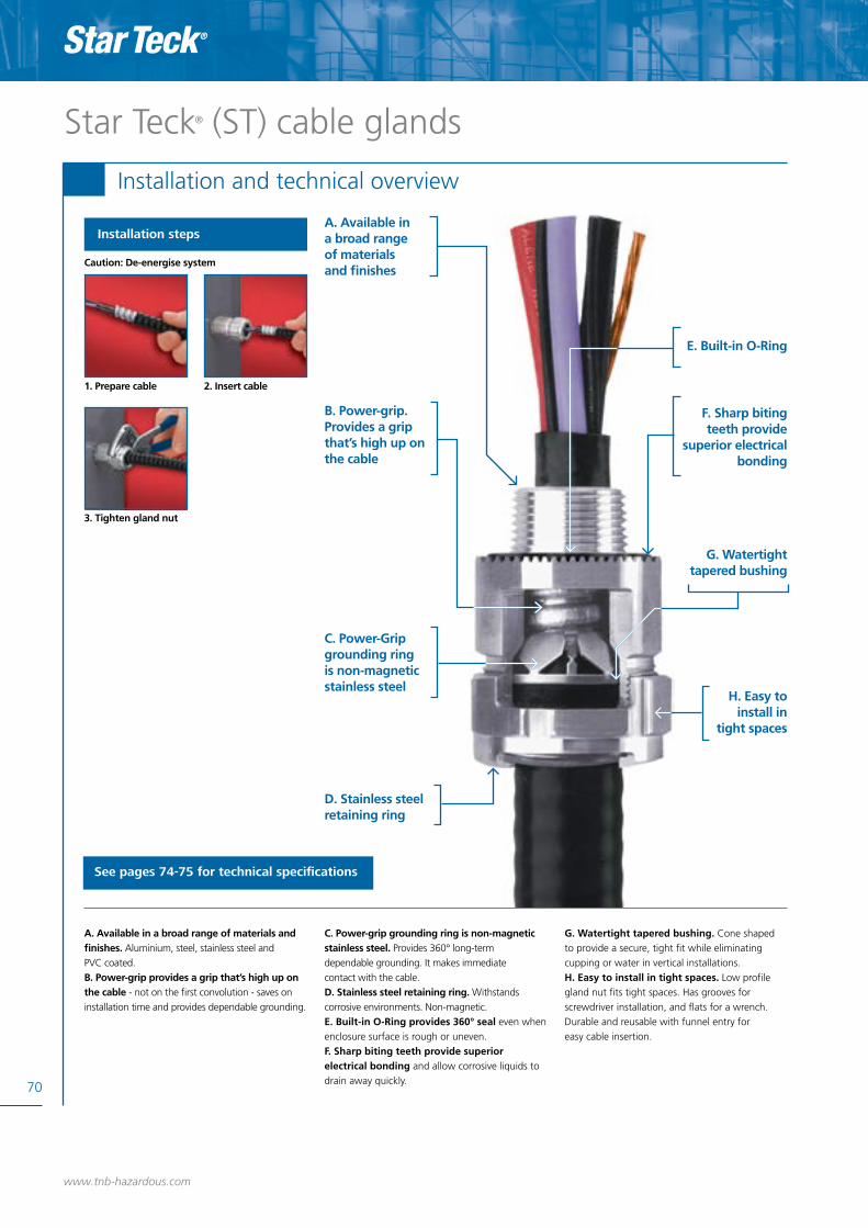
70
Star Teck® (ST) cable glands
Installation and technical overview
Installation steps
1. Prepare cable 2. Insert cable
3. Tighten gland nut
A. Available in a broad range of materials and finishes. Aluminium, steel, stainless steel andPVC coated.B. Power-grip provides a grip that’s high up on the cable - not on the first convolution - saves on installation time and provides dependable grounding.
C. Power-grip grounding ring is non-magnetic stainless steel. Provides 360° long-termdependable grounding. It makes immediatecontact with the cable.D. Stainless steel retaining ring. Withstands corrosive environments. Non-magnetic.E. Built-in O-Ring provides 360° seal even whenenclosure surface is rough or uneven.F. Sharp biting teeth provide superior electrical bonding and allow corrosive liquids to drain away quickly.
G. Watertight tapered bushing. Cone shapedto provide a secure, tight fit while eliminating cupping or water in vertical installations.H. Easy to install in tight spaces. Low profile gland nut fits tight spaces. Has grooves for screwdriver installation, and flats for a wrench. Durable and reusable with funnel entry for easy cable insertion.
See pages 74-75 for technical specifications
E. Built-in O-Ring
F. Sharp biting teeth provide
superior electricalbonding
G. Watertighttapered bushing
H. Easy to install in
tight spaces
www.tnb-hazardous.com
A. Available in a broad range of materials and finishes
B. Power-grip. Provides a grip that’s high up on the cable
C. Power-Grip grounding ring is non-magnetic stainless steel
D. Stainless steel retaining ring
Caution: De-energise system

Star Teck XP® (STX) cable glands
71
Installation and technical overview
Installation steps
A. Hub has hexagonal shape for dependable tool grip. Easy installation.B. User-friendly internal splines allow installer to tighten gland nut either on or off enclosure.C. Highly efficient, highly visible union features twist-on action for easy connection and disconnection; red color assures high visibility, easy recognition. Union also serves as a “puller” during disassembly.D. Corrosion resistant copper-free construction. All-aluminium body and gland nut resist corrosion and oxydation.
E. Stainless steel retaining ring. Withstands corrosive environments. Non-magnetic.F. Easy fill and assembly. Sealing chamber is easier to fill, requires less sealing compound - saves time, material. Flame path is optimally designed to allow for easy insertion into hub. Quick-turn lock unitises assembly during installation.G. Power-grip provides grip that’s high up on cable armour - not on first convolution - saves on installation time and provides dependable grounding.Non-magnetic stainless steel Power-grip grounding ring assures 360° long-term dependable grounding.Also provides phenomenal tensile pull out resistance.
H. Easy to install in tight spaces. Low profile gland nut fits tightest spaces. Has grooves for hammer / screwdriver installation and flats for wrench-gripping. Durable and reusable with funnel entry for easy cable insertion.I. Secure, tight fit, tapered bushing. Cone-shapedto provide secure, tight fit while eliminating cupping of water in vertical installations.
A. Hub has hexagonal shape for dependabletool grip
B. User-friendlyInternal splines
C. Highly efficient,highly visibleunion
D. Corrosion resistantcopper-free construction
E. Stainless steel retaining ring
1. Prepare cable 2. Install XP fitting onto cable
3. Tighten gland nut 4. Pot cable (using liquid or putty)
5. Install hub on enclosure
6. Insert cable and tighten red union
See pages 76-77 for technical specifications
F. Easy fill and assembly
G. Power-gripprovides grip
that’s high upon cable
armour
H. Easy to install in
tight spaces
I. Secure, tight fit, tapered
bushing
Star Teck® (R) - installation and technical overview
Caution: De-energise system
www.tnb-hazardous.comA Member of the ABB Group

72
Star Teck Extreme® (STE) cable glands
Installation and technical overview
Installation steps
1. Prepare cable
Caution: De-energise system
2. Insert cable
3. For larger cables, unscrew and discard armour-stop.
4. Remove armour stop
A. Removable armour-stop is factory installed. Fittings come ready to install on smallest cable in its range. For larger cables, simply unscrew armour-stop and discard. No fitting disassembly required.B. Built-in sealing device provides 360º seal even when enclosure surface is rough or unevenC. Copper-free construction. Non-corrosive all aluminium body and gland nut.D. Tapered elastomeric bushing. Cone shaped toprovide a secure, tight fit while elimin ating cuppingof water in vertical installations.
E. Elastomeric collar ring extends cable diameter range per fitting. Matching cable to fitting hubsize is made easy. (Note: The STE 050-DATA collar ring is made of stainless steel).F. Sharp biting teeth provide superior electrical bonding and allow corrosive liquids to drain away quickly.G. Exclusive power-grip provides a grip that’s high up on the cable - not on the firstconvolution - saves on installation time and provides dependable grounding.
H. Power-grip grounding ring is non-magnetic stainless steel. Dual sets of grounding devices ensure 360º long-term dependable grounding. It makes immediate contact with the cable during insertion.I. Built-in cable jacket stripping gauge on each fitting.J. Easy to install in tight spaces. Has grooves for screwdriver installation, and flats fora wrench. Durable and reusable with funnel entryfor easy cable insertion.
See pages 78-79 for technical specifications
A. Removable armour-stop is factory installed
B. Built-in sealing device provides 360º seal
C. Copper-free construction
D. Tapered elastomeric bushing
E. Elastomeric collar ring extends cable diameter range per fitting
F. Sharp biting teeth provide superior
electrical bonding
G. Exclusive power-grip
provides a grip that’s high up
on the cable
H. Power-grip grounding ring
I. Built-incable jacket
stripping gauge
J. Easy to install in tight spaces
www.tnb-hazardous.com
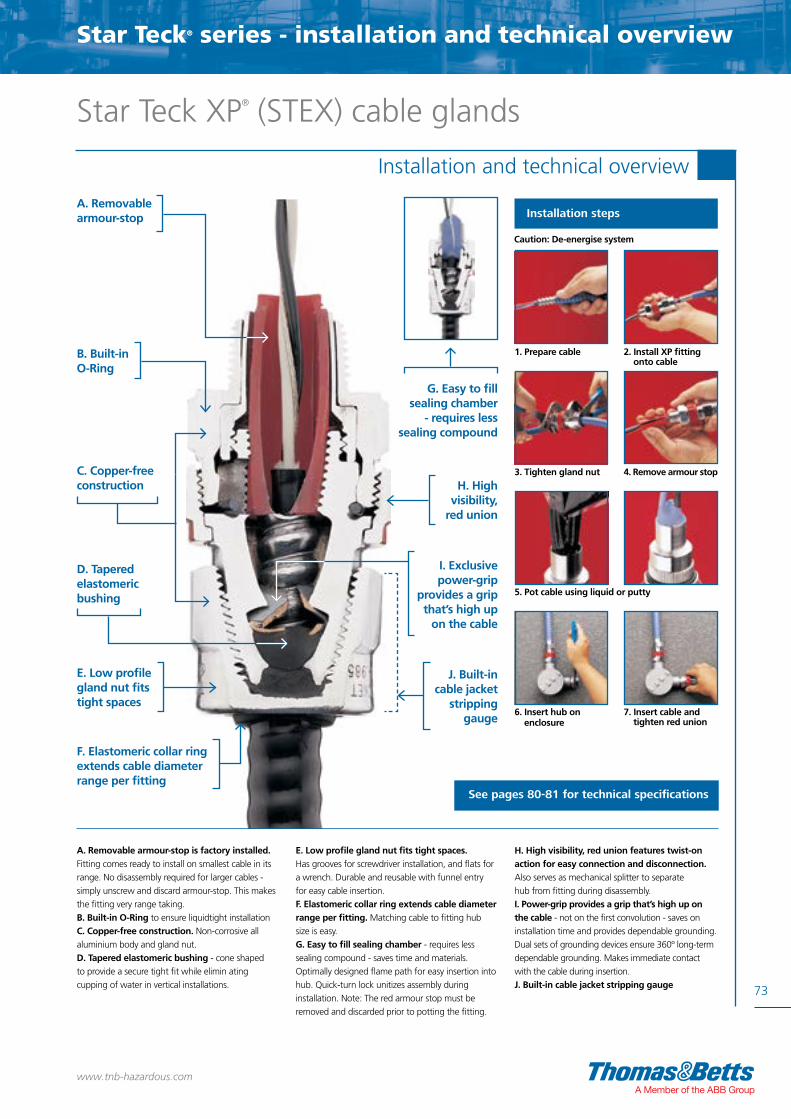
Star Teck XP® (STEX) cable glands
73
Installation and technical overview
Installation steps
A. Removable armour-stop is factory installed. Fitting comes ready to install on smallest cable in its range. No disassembly required for larger cables - simply unscrew and discard armour-stop. This makes the fitting very range taking.B. Built-in O-Ring to ensure liquidtight installationC. Copper-free construction. Non-corrosive all aluminium body and gland nut.D. Tapered elastomeric bushing - cone shaped to provide a secure tight fit while elimin ating cupping of water in vertical installations.
E. Low profile gland nut fits tight spaces. Has grooves for screwdriver installation, and flats for a wrench. Durable and reusable with funnel entry for easy cable insertion.F. Elastomeric collar ring extends cable diameter range per fitting. Matching cable to fitting hub size is easy.G. Easy to fill sealing chamber - requires less sealing compound - saves time and materials. Optimally designed flame path for easy insertion into hub. Quick-turn lock unitizes assembly during installation. Note: The red armour stop must be removed and discarded prior to potting the fitting.
H. High visibility, red union features twist-on action for easy connection and disconnection. Also serves as mechanical splitter to separate hub from fitting during disassembly.I. Power-grip provides a grip that’s high up on the cable - not on the first convolution - saves on installation time and provides dependable grounding.Dual sets of grounding devices ensure 360º long-term dependable grounding. Makes immediate contact with the cable during insertion.J. Built-in cable jacket stripping gauge
A. Removable armour-stop
B. Built-in O-Ring
C. Copper-free construction
D. Tapered elastomeric bushing
E. Low profile gland nut fits tight spaces
F. Elastomeric collar ring extends cable diameter range per fitting
1. Prepare cable 2. Install XP fitting onto cable
3. Tighten gland nut 4. Remove armour stop
5. Pot cable using liquid or putty
6. Insert hub on enclosure
7. Insert cable and tighten red union
Caution: De-energise system
See pages 80-81 for technical specifications
G. Easy to fill sealing chamber
- requires less sealing compound
H. High visibility,
red union
I. Exclusive power-grip
provides a grip that’s high up
on the cable
J. Built-in cable jacket
stripping gauge
Star Teck® series - installation and technical overview
www.tnb-hazardous.comA Member of the ABB Group

• Available in a broad range of materials and finishes; aluminium, steel, stainless steel & PVC coated• Easy installation and dependable grounding• Built in O-ring provides 360º seal• Sharp biting teeth provide superior electrical bonding• Watertight tapered bushing eliminates cupping in
vertical installations• Low profile gland nut for installation into tight spaces• Designed to accommodate a broad range of cables
74
Approvals / Characteristics Features
Star Teck® ST seriesGlands for Teck and ACWU cable
UL Listed and CSA Certified for hazardous locations:UL E38947CSA 023086, AEXClass I, Class II groups E, F & GClass III Type 4, 4x; Exe II Zone 1
CSA certified for use in Hazardous location applications when used with a certified Class I sealing fitting.
Certification and standards
www.tnb-hazardous.com
Glands for Teck and ACWU cable

Star Teck® ST series
75
Star Teck® (ST) rangeStar Teck® cable fittings are designed to accommodate a broad range of cables, thereby minimizing the possibility of mismatched cables and fittings in the field. They are available in hub sizes from 1/2 to 4 inches, and will handle outer jacket diameters from 0.525 to 4.34 inches
Technical specificationsDimensions
www.tnb-hazardous.comA Member of the ABB Group
Aluminium Range Over Jacket (Inches) Dimensions (Inches)Type Hub Size Min. Max. A B* C
ST038-461S** 3/8” 0.344 0.535 0.344 2.020 0.995
ST050-462 1/2” 0.525 0.650 0.390 2.020 1.224
ST050-464 1/2” 0.600 0.760 0.480 2.020 1.363
ST050-465 1/2” 0.725 0.885 0.607 2.133 1.633
ST050-466 1/2” 0.825 0.985 0.607 2.133 1.633
ST075-467 3/4” 0.880 1.065 0.809 2.450 2.080
ST075-468 3/4” 1.025 1.205 0.809 2.450 2.080
ST100-469 1 1.187 1.375 1.034 2.601 2.230
ST125-470 1 1/4” 1.350 1.625 1.177 3.282 2.824
ST125-550 1 1/4” 1.500 1.625 1.365 3.282 2.824
ST125-471 1 1/4” 1.600 1.875 1.365 3.282 2.824
ST150-472 1 1/2” 1.700 1.965 1.552 3.620 3.260
ST150-473 1 1/2” 1.900 2.187 1.595 3.620 3.260
ST200-551 2 1.900 2.187 1.710 3.640 3.620
ST200-474 2 2.100 2.375 1.990 3.640 3.620
ST200-475 2 2.300 2.565 2.052 3.640 4.020
ST200-476 2 2.500 2.750 2.052 3.640 4.020
ST250-477 2 1/2” 2.380 2.640 2.255 4.700 4.750
ST250-478 2 1/2” 2.580 2.840 2.455 4.700 4.750
ST300-479 3 2.790 3.060 2.655 4.700 5.050
ST300-480 3 3.000 3.270 2.885 4.790 5.480
ST300-481 3 3.210 3.480 3.057 4.790 5.480
ST350-482 3 1/2” 3.420 3.690 3.285 4.790 5.980
ST350-483 3 1/2” 3.610 3.870 3.455 4.790 5.980
ST400-484 4 3.810 4.030 3.625 4.840 6.435
ST400-485 4 3.965 4.185 3.770 4.840 6.435
ST400-486 4 4.120 4.340 3.935 4.840 6.435
Note: When using fittings on single conductor cable, aluminium fittings and aluminium locknuts must be used *Approximate dimension before installation, **Only available in steel ***For Steel version, add S to the reference, e.g. ST050-464S, for Stainless Steel version, add SS to the reference, e.g. ST050-464SS, for PVC-Coated Aluminium and Steel version, add PVC to the reference, e.g. ST050-464PVC or ST050-464SPVC
B
C A
Retaining ring(stainless steel)
Bushing(elastomer)
Gland nut(aluminium) Grounding ring
(stainless steel)Body(aluminium)
O-Ring(elastomer)
Hub

• Hub has hexagonal shape for dependable tool grip• Internal splines allow installer to tighten gland nut either on or off enclosure• Provides grip high up on cable armour, saves installation time and provides dependable grounding • Tapered bushing to provide secure, tight fit while eliminating cupping in vertical installations• Low profile gland nut for installation into tight spaces• Designed to accommodate a broad range of cables
76
Approvals / Characteristics Features
Star Teck XP® (STX) seriesHazardous location glands for Teck cable
UL Listed and CSA Certified for hazardous locations:UL E82038UL Class I groups A, B, C & DUL Class II E, F & G, Div 1 CSA 023086Class I Div 1 & 2, groups A, B, C & DClass II Div 1 & 2, groups E, F & GClass III Types 4x, 6P
Certification and standards
www.tnb-hazardous.com
Star Teck XPHazardous location glands for Teck cable

Star Teck XP® (STX) series
77
Technical specificationsDimensions
www.tnb-hazardous.comA Member of the ABB Group
Max. VolumeAluminium of Sealing Range Over Jacket (Inches) Dimensions (Inches)Type Hub Size Compound (cm3) Min. Max. A B* C
STX050-462 1/2” 5 0.525 0.650 0.395 2.50 1.63
STX050-464 1/2” 5 0.600 0.760 0.485 2.50 1.63
STX075-465 3/4” 8 0.725 0.885 0.607 2.62 1.82
STX075-466 3/4” 8 0.825 0.985 0.715 2.62 1.82
STX100-467 1 16 0.880 1.065 0.750 2.83 2.30
STX100-468 1 16 1.025 1.205 0.895 2.83 2.30
STX125-469 1 1/4” 23 1.187 1.375 1.057 3.05 2.51
STX150-470 1 1/2” 43 1.350 1.625 1.177 3.76 3.26
STX150-550 1 1/2” 43 1.500 1.625 1.365 3.76 3.26
STX150-471 1 1/2” 43 1.600 1.875 1.465 3.76 3.26
STX200-472 2 72 1.700 1.965 1.552 4.05 3.62
STX200-473 2 72 1.900 2.187 1.752 4.05 3.62
STX200-474 2 72 2.100 2.375 1.990 4.15 4.02
STX250-475 2 1/2” 147 2.300 2.565 2.180 4.31 4.58
STX250-476 2 1/2” 147 2.500 2.750 2.360 4.31 4.58
STX300-478 3 286 2.580 2.840 2.455 5.64 5.10
STX300-479 3 286 2.790 3.060 2.655 5.80 5.33
STX350-480 3 1/2” 366 3.000 3.270 2.859 6.32 5.79
STX350-481 3 1/2” 366 3.210 3.480 3.057 6.32 5.79
STX400-482 4 614 3.420 3.690 3.285 6.63 6.19
STX400-483 4 614 3.610 3.870 3.455 6.63 6.19
STX400-484 4 614 3.810 4.030 3.625 7.09 6.90
STX400-485 4 614 3.965 4.185 3.770 7.09 6.90
Note: Sealing compound not included. Order separately *Approximate dimension before installation, **For steel version, add S to the reference, e.g. STX050-464S
Sealing Compounds
Type Description Volume (cm3)
SC4-KIT-1* Liquid type sealing compound 50
(includes pouch of sealing compound with customizable nozzle and damming fiber)
SC65** Putty type sealing compound (cut-to-length stick) 34
* Use SC4-KIT-1 liquid compound for shielded cables and all power cables with less than 4 conductors (including ground). **We do not recommend SC65 for use with shielded cables. Suitable for use on cables with a maximum of four conductors (including ground)
Series Star Teck XP® (STX) rangeStar Teck XP® (STX) cable glands are designed to accommodate a broad range of cables, thereby minimizing the possibility of mismatched cables and fittings in the field. They are available in hub sizes from 1/2 to 4 inches, and will handle outer jacket diameters from 0.525 to 4.185 inches

• Removable armour stop is factory installed• Built-in sealing device provides 360º seal even when enclosure surface is rough or uneven• Tapered bushing to provide secure, tight fit while eliminating cupping in vertical installations• Elastomeric collar ring extends cable diameter range• Built-in jacket stripping gauge on each fitting• Low profile gland nut for installation into tight spaces• Designed to accommodate a broad range of cables
78
Approvals / Characteristics Features
Star Teck Extreme® (STE) seriesRange-taking glands for Teck and ACWU cable
UL Listed and CSA Certified for hazardous locations:UL E38947CSA 023086, AEXClass I, Class II groups E, F & GClass III Type 4, 4x or Type 6PExe II Zone 1
CSA certified for use in Hazardous location applications when used with a certified Class I sealing fitting.
Certification and standards
www.tnb-hazardous.com
Star Teck Extreme

Star Teck Extreme® (STE) series
79
Star Teck Extreme® (STE)Star Teck Extreme® (STE) cable glands are designed to accommodate a broad range of cables and each hub size overlaps the adjacent hub range, thereby minimizing the possibility of mismatched cables andfittings in the field. Available in hub sizes from 1/2 to 4 inches, Star Teck Extreme fittings will terminate outer jacket diameters from 0.5 to 4.34 inches
Technical specificationsDimensions
www.tnb-hazardous.comA Member of the ABB Group
A1 A2 Gland Range Range Throat Dia. Throat Dia. B* C Max.Aluminium Strip Torque Over Jacket (in) Over Armour (in) Min (in) w/ Min (in) w/o Overall O.D.Type Hub Size Length (Ib - in) Min. Max. Min. Max. Armour Stop Armour Stop (in) (in)
STE050-DATA 1/2” 7/8” 300 0.500 0.700 0.410 0.610 0.375 0.515 2.10 1.36
STE050 1/2” 1 1/4” 300 0.600 0.985 0.520 0.895 0.505 0.617 2.52 1.63
STE075 3/4” 1 1/4” 600 0.860 1.205 0.780 1.125 0.645 0.819 2.84 2.08
STE100 1 1 1/4” 700 0.950 1.375 0.870 1.295 0.785 1.044 3.02 2.30
STE125 1 1/4” 1 3/4” 1000 1.150 1.625 0.990 1.465 0.970 1.250 4.01 2.82
STE150 1 1/2” 1 3/4” 1200 1.440 1.965 1.280 1.805 1.260 1.562 4.29 3.25
STE200 2 1 3/4” 1600 1.825 2.375 1.665 2.215 1.645 1.995 4.12 3.60
STE250 2 1/2” 2 1/2” 1600 2.265 2.840 2.105 2.680 2.075 2.424 5.67 4.75
STE300 3 2 1/2” 1600 2.670 3.270 2.545 3.145 2.531 2.890 5.78 5.40
STE350 3 1/2” 2 1/2” 1600 3.220 3.870 3.090 3.640 3.065 3.414 5.74 5.90
STE400 4 2 1/2” 1600 3.665 4.340 3.550 4.225 3.525 3.914 5.79 6.40
Note: To order fittings complete with aluminium BondStar locknut and lug, add the suffix “GRL” to the catalogue number, e.g. STE050GRL *Approximate dimension before installation, **For Steel version, add S to the reference, e.g. STE050S

• Removable armour stop is factory installed• Built-in sealing device provides 360º seal when enclosure surface is rough or uneven• Tapered bushing to provide secure, tight fit while eliminating cupping in vertical installations• Elastomeric collar ring extends cable diameter range• Built-in jacket stripping gauge on each fitting• Low profile gland nut for installation into tight spaces• Designed to accommodate a broad range of cables
80
Approvals / Characteristics Features
Star Teck Extreme XP® (STEX) seriesRange-taking glands for Teck cable
UL Listed and CSA Certified for hazardous locations:UL E82038UL Class I groups A, B, C & DUL Class II E, F & G, Div 2 CSA 023086Class I Div 1 & 2, groups A, B, C & DClass II Div 1 & 2, groups E, F & GClass III Types 4x, 6P
Certification and standards
www.tnb-hazardous.com
Star Teck Extreme XP

Star Teck Extreme XP® (STEX) series
81
Star Teck Extreme XP® (STEX)Star Teck Extreme XP® (STEX) cable glands are designed to accommodate a broad range of cables and each hub range overlaps the adjacent hub range, thereby minimizing the possibility of mismatched cables and fittings in the field. They are available in hub sizes from 1/2 to 4 inches, and will handle outer jacket diameters from 0.525 to 3.870 inches
Technical specificationsDimensions
www.tnb-hazardous.comA Member of the ABB Group
A1 A2 Compound Range Over Range Over Throat Dia. Throat Dia. B* C Max. Req’d (approx.) Aluminium Jacket (in) Armour (in) Min (in) w/ Min (in) w/o Length O.D. SC65/SC4KITType Hub Size Min. Max. Min. Max. Armour Stop Armour Stop (in) (in) Liquid (CC)
STX050-462 1/2” 0.525 0.650 0.415 0.570 N/A*** 0.400 2.500 1.630 5
STX050-464 1/2” 0.600 0.760 0.490 0.680 N/A*** 0.480 2.530 1.630 5
STEX075 3/4” 0.600 0.985 0.520 0.895 0.500 0.670 3.400 1.820 8
STEX100 1 0.860 1.205 0.780 1.125 0.645 0.825 3.580 2.300 16
STEX125 1 1/4” 0.950 1.375 0.870 1.295 0.829 1.076 3.920 2.510 23
STEX150 1 1/2” 1.150 1.625 0.990 1.465 0.953 1.280 5.020 3.260 43
STEX200 2 1.440 1.965 1.280 1.805 1.245 1.565 5.120 3.620 72
STEX250 2 1/2” 1.825 2.375 1.665 2.215 1.630 2.000 5.170 4.580 147
STEX300 3 2.265 2.840 2.105 2.680 2.066 2.495 6.610 5.100 286
STEX350 3 1/2” 2.670 3.270 2.545 3.145 2.522 2.895 7.380 5.790 366
STEX400 4 3.220 3.870 3.090 3.640 3.060 3.520 7.650 6.190 614
Note: To order fittings complete with aluminium BondStar locknut and lug, add the suffix “GRL” to the catalogue number, e.g. STE050GRL *Approximate dimension before installation, **For Steel version, add S to the reference, e.g. STE050S
Sealing compounds
Type Description Volume (cm3)
SC4-KIT-1* Liquid type sealing compound 50
(includes pouch of sealing compound with customizable nozzle and damming fiber).
SC65** Putty type sealing compound (cut-to-length stick) 34
* Use SC4-KIT-1 liquid compound for shielded cables and all power cables with less than 4 conductors (including ground) **We do not recommend SC65 for use with shielded cables. Suitable for use on cables with a maximum of four conductors (including ground)

• First truly adjustable, range-taking fitting
• Exclusive swash-plate design allows adjustments from
90 to 180 degrees
• Full circular bore for trouble-free cable insertion
• Alignment guides facilitate installation of fittings at
same angle
• Requires no disassembly prior to installation; can also
be easily disconnected
• For use with teck cable, jacketed metal-clad cable
(ACWU) or metal clad cable (MC)
82
Approvals / Characteristics Features
UL Listed and CSA Certified for hazardous locations as outlined in the CEC:UL E38947CSA 023086, AEXClass I, Class II groups E, F & GClass III and enclosures Type 4, 4x and 6PExe II IP68
Certification and standards
www.tnb-hazardous.com
Star Teck Extreme DirectorTM (STED) series
Adjustable range-taking cable glandDirector

Star Teck® Extreme Director
TM (STED) series
83
Technical specificationsDimensions
www.tnb-hazardous.comA Member of the ABB Group
Gland Range Range Throat Dia. Throat Dia. Torque Over Jacket (in) Over Armour (in) Min (in) w/ Min (in) w/o OverallType Hub Size (Ib - in) Min. Max. Min. Max. Armour Stop Armour Stop (in)
STED050 1/2” 450 0.600 0.885 0.520 0.795 0.505 0.617 5.375
STED075 3/4” 600 0.860 1.205 0.780 1.125 0.645 0.819 5.875
Installation steps
Install fitting into enclosure
Insert cable and tighten (as usual)
Rotate fitting to desired angle
Caution: De-energise system
Assembly:
bluecompressionnut
collar ring
grounding ring
bushing
clamp
hub
alse ring
body
removablearmour stop
gland nut
Assembly:

• For use in any data and control applications sensitive to floating voltage differences
• Open-sided lay-in grounding lug is CSA and UL approved
and has a 4-14 AWG wire range
• Choice of three grounding locations on the
circumference of the installed grounding locknut
facilitates installation of grounding lug
84
Approvals / Characteristics Features
Bond Star TM
Grounding locknut
www.tnb-hazardous.com

Bond Star TM Grounding locknut
85
www.tnb-hazardous.comA Member of the ABB Group
Type Hub Sizes (in) Obsoleted Items
STE050-DATAGRL 1/2” STE050-DATAGR
STE050GRL 1/2” STE050GR
STE075GRL 3/4” STE075GR
STE100GRL 1” STE100GR
STE125GRL 1 1/4” STE125GR
STE150GRL 1 1/2” STE150GR
STE200GRL 2” STE200GR
STE250GRL 2 1/2” STE250GR
STE300GRL 3” STE300GR
STE350GRL 3 1/2” STE350GR
STE400GRL 4” STE400GR
Star Teck extreme fittings with Bond Star grounding locknut Technical specifications
Bond StarTM grounding locknut only
Type Sizes (in) Description
L050GRL 1/2” Locknut with Lay-in Lug and Screw
L075GRL 3/4” Locknut with Lay-in Lug and Screw
L100GRL 1” Locknut with Lay-in Lug and Screw
L125GRL 1 1/4” Locknut with Lay-in Lug and Screw
L150GRL 1 1/2” Locknut with Lay-in Lug and Screw
L250GRL 2 1/2” Locknut with Lay-in Lug and Screw
L300GRL 3” Locknut with Lay-in Lug and Screw
L350GRL 3 1/2” Locknut with Lay-in Lug and Screw
L400GRL 4” Locknut with Lay-in Lug and Screw
L500GRL 5” Locknut with Lay-in Lug and Screw
Lay-in lug
Type Screw For Hub Sizes (in)
GRL-LUG1032 #10, 32 TPI 1/2”, 3/4”, 1”
GRL-LUG1/4-20 1/4, 20 TPI 1 1/4” - 6”

• Forms a watertight seal around the cable and at the enclosure entry• Designed to accommodate a wide range of cables to provide a means to terminate at junction boxes, control centres, panel boards, and enclosures for motor control and electrical distribution equipment.• Compact diameter eases installation in confined areas• Available in 1/2 to 4-inch NPT trade sizes• Ranges overlap from one fitting to another, thus
simplifying the choice
86
Approvals / Characteristics Features
IBERVILLE® TEKTM
Cable glands
CSA Certified for hazardous locations as outlined in the CEC:CSA 051586Class I groups A, B, C & DClass II groups E, F & GClass III Types 4, 4x
Certification and standards
www.tnb-hazardous.com

IBERVILLE® TEKTM cable glands
87
Technical specificationsDimensions
www.tnb-hazardous.comA Member of the ABB Group
Gland Exposed Hex. Key Dia. Over Throat Nut Overall Length Gland Cat. No. Trade Size Cable Jacket (Inches) I.D O.D Length (tightened) NutAluminium Steel (Inches) Min. Max. (Inches) (Inches) (Inches) (Inches) (Inches)
CI-TEK-50-066 CI-TEK-50-066-S 1/2” 0.500 0.660 0.390 1.250 2-5/8 1-3/4 1-3/16
CI-TEK-50-079 CI-TEK-50-079-S 1/2” 0.620 0.790 0.500 1.375 2-5/8 1-3/4 1-5/16
CI-TEK-50-092 CI-TEK-50-092-S 1/2” 0.750 0.920 0.620 1.500 2-5/8 1-3/4 1-7/16
CI-TEK-75-105 CCI-TEK-75-105-S 3/4” 0.870 1.050 0.760 1.750 2-3/4 1-3/4 1-5/8
CI-TEK-75-120 CI-TEK-75-120-S 3/4” 1.020 1.200 0.830 1.937 2-3/4 1-3/4 1-13/16
CI-TEK-100-137 CI-TEK-100-137-S 1 1.180 1.370 1.030 2.375 2-7/8 2 2-1/4
CI-TEK-125-157 CI-TEK-125-157-S 1 1/4” 1.350 1.570 1.230 2.500 3-5/8 2-5/8 2-3/8
CI-TEK-125-176 CI-TEK-125-176-S 1 1/4” 1.540 1.760 1.400 2.625 3-5/8 2-5/8 2-1/2
CI-TEK-150-198 CI-TEK-150-198-S 1 1/2” 1.730 1.980 1.590 3.000 4 2-7/8 2-3/4
CI-TEK-200-220 CI-TEK-200-220-S 2 1.960 2.200 1.810 3.250 4-1/4 3-1/8 3
CI-TEK-200-241 CI-TEK-200-241-S 2 2.180 2.410 2.020 3.500 4-1/4 3-1/8 3-1/4
CI-TEK-200-262 CI-TEK-200-262-S 2 2.390 2.620 2.060 3.750 4-1/4 3-1/8 3-1/2
CI-TEK-250-284 CI-TEK-250-284-S 2 1/2” 2.600 2.840 2.400 5.000 6-7/16 5-1/4 4-1/2
CI-TEK-300-306 CI-TEK-300-306-S 3 2.820 3.060 2.620 5.625 6-3/4 5-1/2 5-1/4
CI-TEK-300-328 CI-TEK-300-328-S 3 3.040 3.280 2.843 5.625 6-3/4 5-1/2 5-1/4
CI-TEK-300-350 CI-TEK-300-350-S 3 3.260 3.500 3.030 5.625 6-3/4 5-1/2 5-1/4
CI-TEK-400-371 CI-TEK-400-371-S 4 3.480 3.710 3.230 6.500 7-1/8 5-3/4 6
CI-TEK-400-392 CI-TEK-400-392-S 4 3.690 3.920 3.450 6.500 7-1/8 5-3/4 6
CI-TEK-400-413 CI-TEK-400-413-S 4 3.900 4.130 3.680 6.500 7-1/8 5-3/4 6
CI-TEK-400-433 CI-TEK-400-433-S 4 4.110 4.330 3.860 6.500 7-1/8 5-3/4 6
Installation steps
Install fitting on enclosure Prepare cable
Slacken gland nut and insert prepared cable
Hand tighten gland nut to hold cable, then wrench tighten
Caution: De-energise system
Locknut (zinc or steel)
Gland nut (aluminium or steel)
O-ring (elastomer)
Grounding spring (stainless steel)
Pressure ring (aluminium)
Main O-ring (elastomer)
Biting teeth
Body (aluminium or steel)

• Incorporates integral means for the sealing of conductors, together with a long and tight flame propagation path to prevent the escape of hot gases
• Suitable for either single or multi-conductor cables• Available in 1/2 to 2-inch NPT trade sizes• Designed for ease of installation and total reliability
88
Approvals / Characteristics Features
IBERVILLE® TCAXTM
Explosion-proof Teck cable glands
UL Listed and CSA Certified for hazardous locations as outlined in the CEC:UL E82038UL Class I groups A, B, C & DUL Class II E, F & G, Div 2 CSA 051586Class I groups A, B, C & DClass II groups E, F & GClass III Types 4, 4x
Certification and standards
www.tnb-hazardous.com

IBERVILLE® TCAXTM explosion-proof Teck cable glands
89
Technical specificationsDimensions
www.tnb-hazardous.comA Member of the ABB Group
Dia. Over Fitting (Inches) Cat. No. Trade Size Cable Jacket (Inches) Throat Body/Gland Adaptor Overall ExposedAluminium (Inches) Min. Max. (Inches) Nut O.D Nut O.D Length Length
CI-TCAX-50-063-P 1/2” 0.500 0.630 0.380 1-5/8 1-3/8 3-1/2 2-7/8
CI-TCAX-50-078-P 1/2” 0.620 0.780 0.490 1-5/8 1-3/8 3-1/2 2-7/8
CI-TCAX-50-089-P 1/2” 0.760 0.890 0.530 1-5/8 1-3/8 3-1/2 2-7/8
CI-TCAX-50-098-P 1/2” 0.870 0.980 0.530 1-5/8 1-3/8 3-1/2 2-7/8
CI-TCAX-75-106-P 3/4” 0.900 1.060 0.740 1-7/8 1-5/8 3-3/4 3
CI-TCAX-75-118-P 3/4” 1.040 1.180 0.740 1-7/8 1-5/8 3-3/4 3
CI-TCAX-100-135-P 1 1.160 1.350 0.890 2-1/4 1-7/8 4-1/4 3-1/2
CI-TCAX-125-151-P 1 1/4” 1.330 1.510 1.180 2-3/4 2-1/2 4-1/4 3-1/2
CI-TCAX-125-167-P 1 1/4” 1.490 1.670 1.240 2-3/4 2-1/2 4-1/4 3-1/2
CI-TCAX-125-182-P 1 1/4 1.650 1.820 1.240 2-3/4 2-1/2 4-1/4 3-1/2
CI-TCAX-150-192-P 1 1/2” 1.730 1.920 1.480 3-1/4 3 4-1/2 3-3/4
CI-TCAX-150-208-P 1 1/2” 1.900 2.080 1.480 3-1/4 3 4-1/2 3-3/4
CI-TCAX-200-231-P 2 2.060 2.310 1.890 3-3/4 3-1/4 5-1/8 4-3/8
CI-TCAX-200-250-P 2 2.280 2.500 1.950 3-3/4 3-1/4 5-1/8 4-3/8
Installation steps
Prepare cable Install TCAX fitting on cable
Tighten gland nut
Insert adaptor on enclosure
Pot cable using liquid or putty
Insert assembly and tighten adaptor nut
Caution: De-energise system
Adaptor (aluminium)
Body (aluminium)
Seal sleeve (aluminium)
Adaptor nut (aluminium)
Armour stop (phenolic)
Bushing (elastomer)
Gland nut (aluminium)
Pressure ring (aluminium)
Sealing compound (liquid or putty)
Grounding fingers (aluminium)
2690
www.tnb-hazardous.com
Rigid conduit fittings

Rigid conduit fittings
91
www.tnb-hazardous.comA Member of the ABB Group
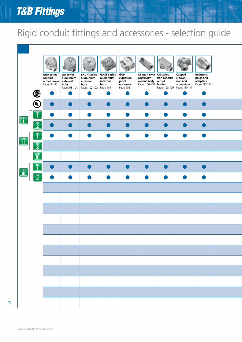
92
Rigid conduit fittings and accessories - selection guide
www.tnb-hazardous.com
GA seriesaluminium external hubs Pages 98-101
GUPexplosion-proof enclosure Page 105
LB and T stylealuminium conduit bodyPages 106-107
GUA seriesconduit outlet boxes Pages 94-97
Capped elbowsiron and aluminiumPages 110-111
Reducers, plugs and adaptersPages 112-113
OE seriesiron conduit outlet bodies Pages 108-109
EXUN seriesaluminium internal hubs Pages 102-103
GASS seriesaluminium internal hubs Page 104
1DIV
1DIV
2DIVI
2DIV
2DIV
1DIV

Rigid conduit fittings and accessories - selection guide
93
UN seriesthree-piece unions Pages 114-115
Sealing cement and fiber Pages 124-125
EYS seriessealing fittings Pages 120-121
EYVF and EVHF seriessealing fittings Pages 122-123
EX seriesaluminium three-piece unions Pages 116-117
EYD & ECD seriesdrain seals and breathers Pages 118-119
www.tnb-hazardous.comA Member of the ABB Group
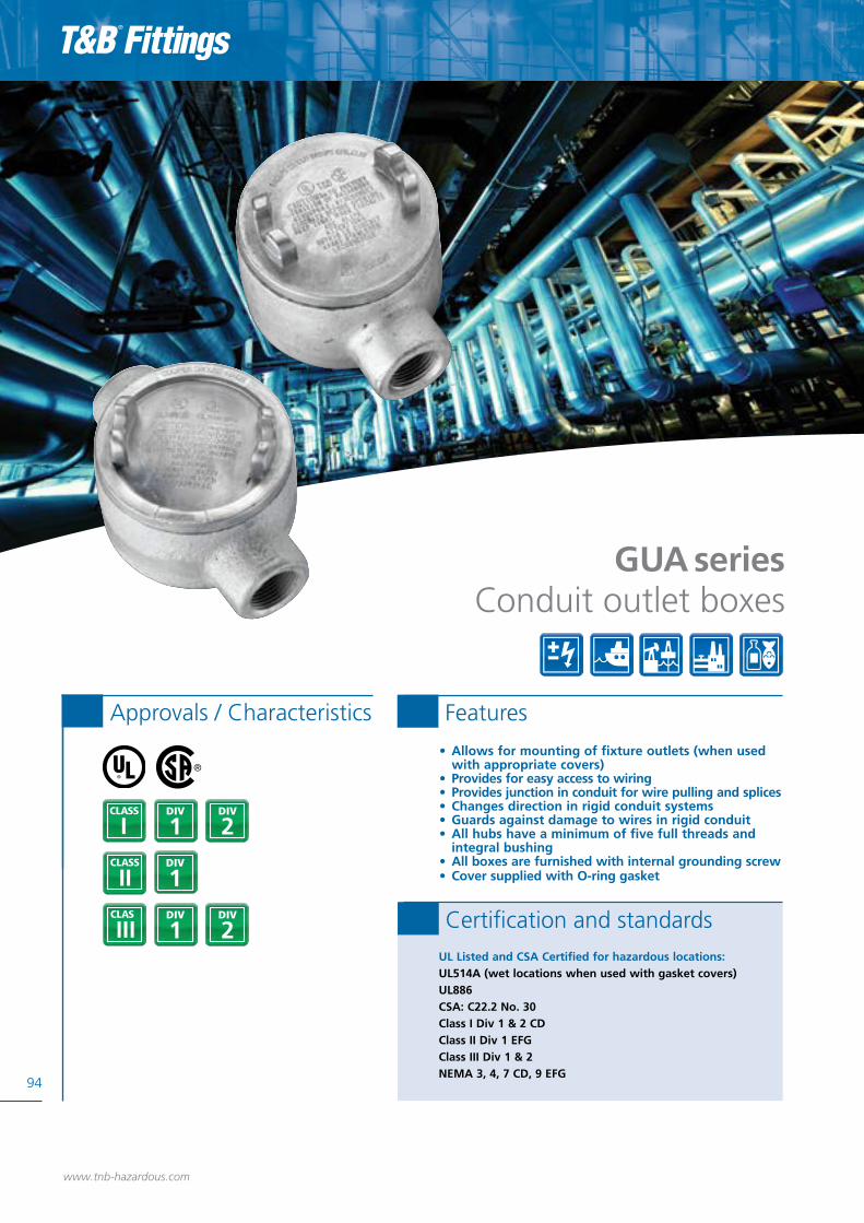
• Allows for mounting of fixture outlets (when used with appropriate covers)• Provides for easy access to wiring• Provides junction in conduit for wire pulling and splices• Changes direction in rigid conduit systems• Guards against damage to wires in rigid conduit• All hubs have a minimum of five full threads and integral bushing• All boxes are furnished with internal grounding screw• Cover supplied with O-ring gasket
94
1DIV
1DIV
2DIV
2DIV
I
1DIV
Approvals / Characteristics Features
GUA seriesConduit outlet boxes
UL Listed and CSA Certified for hazardous locations:UL514A (wet locations when used with gasket covers)UL886CSA: C22.2 No. 30Class I Div 1 & 2 CD Class II Div 1 EFGClass III Div 1 & 2NEMA 3, 4, 7 CD, 9 EFG
Certification and standards
www.tnb-hazardous.com

Conduit outlet boxes - GUA series
GUA Dimensions (Inches) Throat Diameter Cubic InchType Hub Size A B C Min Max Capacity
GUA14-TB 1/2” 1.81 2.50 0.88 0.570 0.610 5.50
GUA16-TB 1/2” 2.00 3.50 0.88 0.570 0.610 13.5
GUA24-TB 3/4” 2.00 2.50 0.88 0.755 0.810 5.30
GUA26-TB 3/4” 2.00 3.50 0.88 0.755 0.810 13.3
GUA36-TB 1” 2.31 3.50 0.88 0.935 1.035 16.2
GUA47-TB 1 1/4” 2.69 4.38 1.00 1.260 1.360 29.0
GUA59-TB 1 1/2” 3.81 5.75 1.06 1.470 1.590 70.0
95Size rangeAll sizes are listed in the tables on each page for each cat. no.
MaterialsBodies: Grade 60-45-10 Ductile Iron (complies with ASTM standard A536)Covers: Die-cast aluminium
FinishBoxes: Zinc plated with aluminium acrylic paintCovers: Natural
Technical specificationsDimensions
www.tnb-hazardous.comA Member of the ABB Group
GUAB Dimensions (Inches) Throat Diameter Cubic InchType Hub Size A B C Min Max Capacity
GUAB14-TB 1/2” 2.25 2.50 0.88 0.570 0.610 6.90
GUAB16-TB 1/2” 2.00 3.50 0.88 0.570 0.610 13.5
GUAB24-TB 3/4” 2.50 2.50 0.88 0.755 0.810 7.90
GUAB26-TB 3/4” 2.00 3.50 0.88 0.755 0.810 13.5
GUAB36-TB 1” 2.31 3.50 1.00 0.935 1.035 15.4
GUAB47-TB 1 1/4” 2.69 4.38 1.00 1.260 1.360 27.5
GUAB59-TB 1 1/2” 3.81 5.75 1.06 1.470 1.590 73.6
GUAB69-TB 2” 4.06 5.75 1.06 1.880 2.047 80.0
GUAB79-TB 2 1/2” 4.06 5.75 1.13 2.320 2.380 98.0
GUAD Dimensions (Inches) Throat Diameter Cubic InchType Hub Size A B C Min Max Capacity
GUAD14-TB 1/2” 1.81 2.50 0.88 0.570 0.610 5.60
GUAD16-TB 1/2” 2.00 3.50 0.88 0.570 0.610 12.5
GUAD24-TB 3/4” 2.00 2.50 0.88 0.755 0.810 5.20
GUAD26-TB 3/4” 2.00 3.50 0.88 0.755 0.810 13.1
GUAD36-TB 1” 2.31 3.50 0.88 0.935 1.035 16.0
GUAD49-TB 1 1/4” 3.81 5.75 1.00 1.260 1.360 76.0
GUAC Dimensions (Inches) Throat Diameter Cubic InchType Hub Size A B C Min Max Capacity
GUAC14-TB 1/2” 2.25 2.50 0.88 0.570 0.610 6.80
GUAC16-TB 1/2” 2.0 3.50 0.88 0.570 0.610 13.1
GUAC24-TB 3/4” 2.0 2.50 0.88 0.755 0.810 5.30
GUAC26-TB 3/4” 2.0 3.50 0.88 0.755 0.810 13.3
GUAC36-TB 1” 2.31 3.50 0.88 0.935 1.035 16.2
GUAC47-TB 1 1/4” 2.69 4.38 1.00 1.260 1.360 29.3
GUAC49-TB 1 1/4” 3.81 5.75 1.00 1.260 1.360 73.6
GUAC59-TB 1 1/2” 3.81 5.75 1.06 1.470 1.590 74.0
GUAC69-TB 2” 4.06 5.75 1.06 1.880 2.047 77.8
A
BC
A
BC
A
BC
A
BC
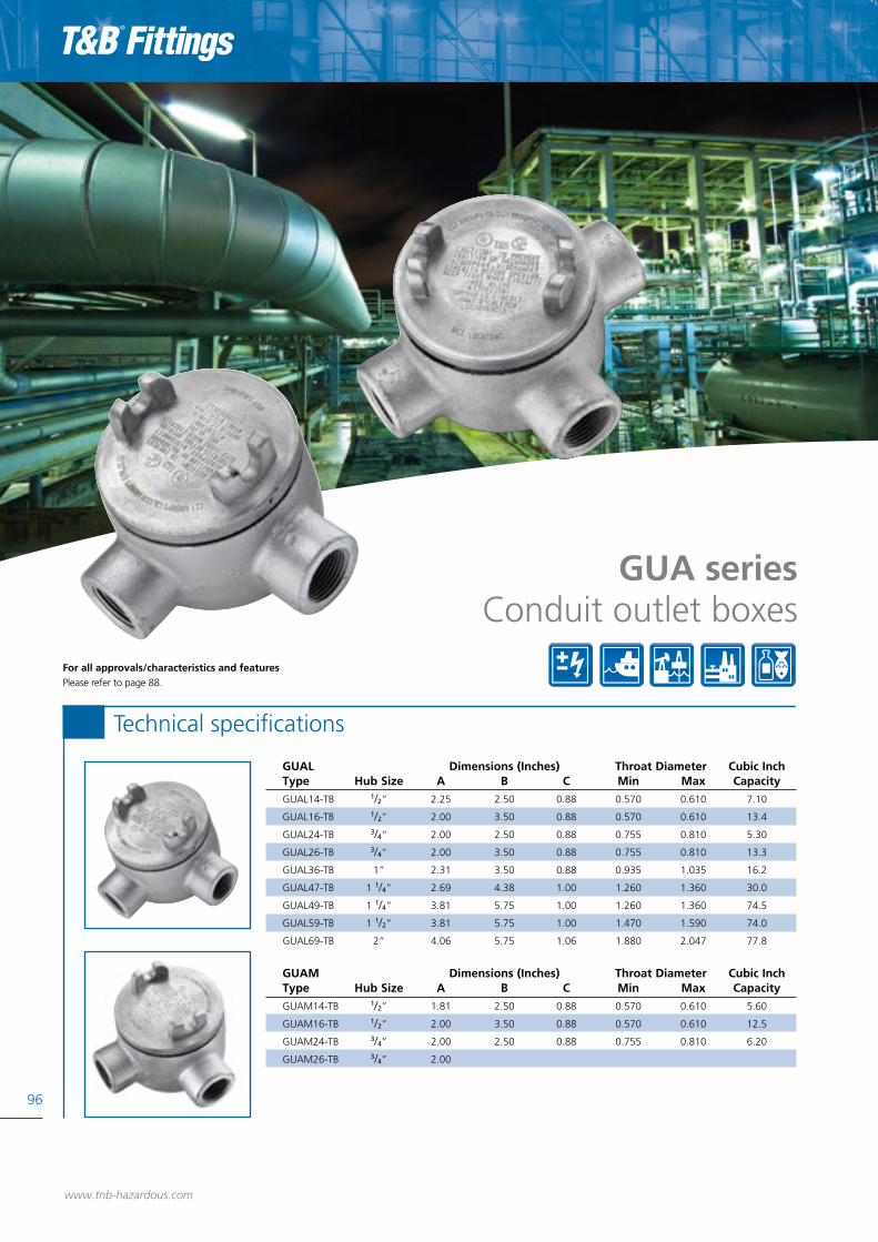
96
www.tnb-hazardous.com
Technical specifications
GUAL Dimensions (Inches) Throat Diameter Cubic InchType Hub Size A B C Min Max Capacity
GUAL14-TB 1/2” 2.25 2.50 0.88 0.570 0.610 7.10
GUAL16-TB 1/2” 2.00 3.50 0.88 0.570 0.610 13.4
GUAL24-TB 3/4” 2.00 2.50 0.88 0.755 0.810 5.30
GUAL26-TB 3/4” 2.00 3.50 0.88 0.755 0.810 13.3
GUAL36-TB 1” 2.31 3.50 0.88 0.935 1.035 16.2
GUAL47-TB 1 1/4” 2.69 4.38 1.00 1.260 1.360 30.0
GUAL49-TB 1 1/4” 3.81 5.75 1.00 1.260 1.360 74.5
GUAL59-TB 1 1/2” 3.81 5.75 1.00 1.470 1.590 74.0
GUAL69-TB 2” 4.06 5.75 1.06 1.880 2.047 77.8
GUAM Dimensions (Inches) Throat Diameter Cubic InchType Hub Size A B C Min Max Capacity
GUAM14-TB 1/2” 1.81 2.50 0.88 0.570 0.610 5.60
GUAM16-TB 1/2” 2.00 3.50 0.88 0.570 0.610 12.5
GUAM24-TB 3/4” 2.00 2.50 0.88 0.755 0.810 6.20
GUAM26-TB 3/4” 2.00
GUA series
Conduit outlet boxesFor all approvals/characteristics and features Please refer to page 88.

Conduit outlet boxes - GUA series
GUAN Dimensions (Inches) Throat Diameter Cubic inchType Hub Size A B C Min Max Capacity
GUAN14-TB 1/2” 2.13 2.50 0.88 0.570 0.610 6.80
GUAN16-TB 1/2” 2.00 3.50 0.88 0.570 0.610 13.5
GUAN24-TB 3/4” 2.31 2.50 0.88 0.755 0.810 7.70
GUAN26-TB 3/4” 2.00 3.50 0.88 0.755 0.810 14.0
GUAN36-TB 1” 2.31 3.50 0.88 0.935 1.035 16.9
GUAN47-TB 1 1/4” 2.69 4.38 1.00 1.260 1.360 31.5
GUAN59-TB 1 1/2” 4.06 5.75 1.06 1.470 1.590 84.0
GUAN69-TB 2” 4.06 5.75 1.06 1.880 2.047 84.0
97Size rangeAll sizes are listed in the tables on each page for each cat. no.
MaterialsBodies: Grade 60-45-10 Ductile Iron (complies with ASTM standard A536)Covers: Die-cast aluminium
FinishBoxes: Zinc Plated with aluminium acrylic paintCovers: Natural
Technical specificationsDimensions
www.tnb-hazardous.comA Member of the ABB Group
GUAT Dimensions (Inches) Throat Diameter Cubic inchType Hub Size A B C Min Max Capacity
GUAT14-TB 1/2” 2.25 2.50 0.88 0.570 0.610 7.00
GUAT16-TB 1/2” 2.0 3.50 0.88 0.570 0.610 13.5
GUAT24-TB 3/4” 2.0 2.50 0.88 0.755 0.810 5.30
GUAT26-TB 3/4” 2.0 3.50 0.88 0.755 0.810 13.3
GUAT36-TB 1” 2.31 3.50 1.00 0.935 1.035 15.9
GUAT37-TB 1” 2.31 3.50 0.88 0.935 1.035 23.3
GUAT47-TB 1 1/4” 2.69 4.38 1.00 1.260 1.360 29.3
GUAT49-TB 1 1/4” 3.81 5.75 1.00 1.260 1.360 77.2
GUAT59-TB 1 1/2” 3.81 5.75 1.06 1.470 1.590 77.7
GUAT69-TB 2” 4.06 5.75 1.06 1.880 2.047 77.8
GUAT79-TB 2 1/2” 4.06 5.75 1.06 2.320 2.380 95.0
GUAX Dimensions (Inches) Throat Diameter Cubic inchType Hub Size A B C Min Max Capacity
GUAX14-TB 1/2” 1.81 2.50 0.88 0.570 0.610 5.20
GUAX16-TB 1/2” 2.0 3.50 0.88 0.570 0.610 13.5
GUAX24-TB 3/4” 2.0 2.50 0.88 0.755 0.810 5.30
GUAX26-TB 3/4” 2.0 3.50 0.88 0.755 0.810 13.3
GUAX36-TB 1” 2.31 3.50 1.00 0.935 1.035 16.0
GUAX37-TB 1” 2.31 3.50 0.88 0.935 1.035 23.3
GUAX47-TB 1 1/4” 2.69 4.38 1.00 1.260 1.360 30.0
GUAX49-TB 1 1/4” 3.81 5.75 1.00 1.260 1.360 72.0
GUAX59-TB 1 1/2” 3.81 5.75 1.06 1.470 1.509 71.0
GUAX69-TB 2” 4.06 5.75 1.06 1.880 2.047 77.8
GUAW Dimensions (Inches) Throat Diameter Cubic inchType Hub Size A B C Min Max Capacity
GUAW14-TB 1/2” 1.81 2.50 0.88 0.570 0.61 5.20
GUAW16-TB 1/2” 2.0 3.50 0.88 0.570 0.61 13.0
GUAW24-TB 3/4” 2.0 2.50 0.88 0.755 0.81 6.50
GUAW26-TB 3/4” 2.0 3.50 0.88 0.755 0.81 13.0
A
BC
A
BC
A
BC
A
BC

• Junction for branch conduits in hazardous locations• Accessible wiring chamber provides a convenient location to maintain or change a system, pull conductors and make splices• Unique mounting pads and external hub design ideal for installations of OEM devices or instruments• Copper-free aluminium provides increased corrosion resistance• Precision cast and machined surfaces permit safer wire pulling
98
1DIV
2DIV
I
1DIV
Approvals / Characteristics Features
GA seriesAluminium external hubs
UL Listed and CSA Certified for hazardous locations:Class I Div 1 & 2 CD Class II Div 1 EFGClass III Div 1 & 2NEMA 4 (when ordered with O-ring installed)
Certification and standards
www.tnb-hazardous.com
1DIV
2DIV
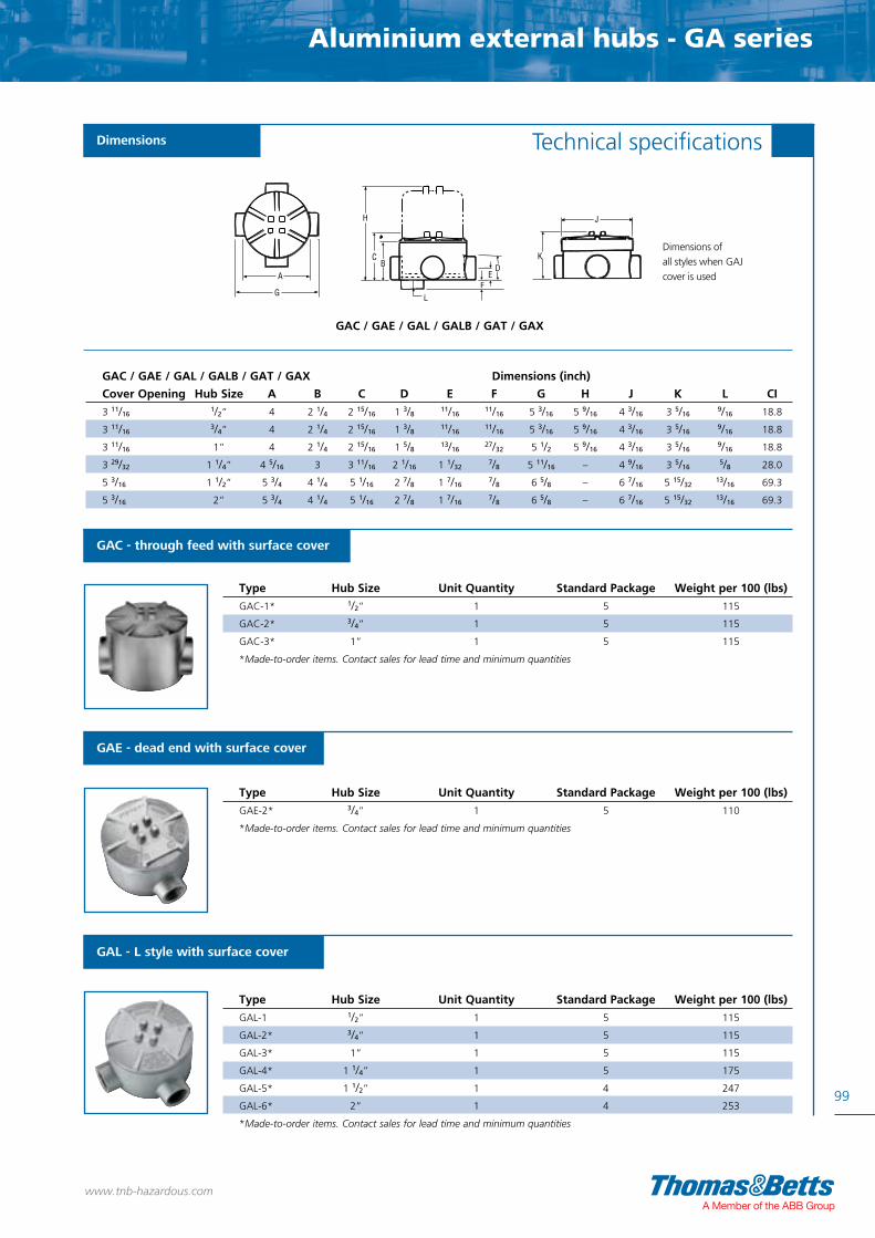
Aluminium external hubs - GA series
99
Technical specifications
www.tnb-hazardous.comA Member of the ABB Group
GAC - through feed with surface cover
GAE - dead end with surface cover
Type Hub Size Unit Quantity Standard Package Weight per 100 (lbs)
GAC-1* 1/2” 1 5 115
GAC-2* 3/4” 1 5 115
GAC-3* 1” 1 5 115
*Made-to-order items. Contact sales for lead time and minimum quantities
Type Hub Size Unit Quantity Standard Package Weight per 100 (lbs)
GAE-2* 3/4” 1 5 110
*Made-to-order items. Contact sales for lead time and minimum quantities
GAL - L style with surface cover
Type Hub Size Unit Quantity Standard Package Weight per 100 (lbs)
GAL-1 1/2” 1 5 115
GAL-2* 3/4” 1 5 115
GAL-3* 1” 1 5 115
GAL-4* 1 1/4” 1 5 175
GAL-5* 1 1/2” 1 4 247
GAL-6* 2” 1 4 253
*Made-to-order items. Contact sales for lead time and minimum quantities
GAC / GAE / GAL / GALB / GAT / GAX Dimensions (inch)
Cover Opening Hub Size A B C D E F G H J K L CI
3 11/16 1/2” 4 2 1/4 2 15/16 1 3/8 11/16 11/16 5 3/16 5 9/16 4 3/16 3 5/16 9/16 18.8
3 11/16 3/4” 4 2 1/4 2 15/16 1 3/8 11/16 11/16 5 3/16 5 9/16 4 3/16 3 5/16 9/16 18.8
3 11/16 1” 4 2 1/4 2 15/16 1 5/8 13/16 27/32 5 1/2 5 9/16 4 3/16 3 5/16 9/16 18.8
3 29/32 1 1/4” 4 5/16 3 3 11/16 2 1/16 1 1/32 7/8 5 11/16 – 4 9/16 3 5/16 5/8 28.0
5 3/16 1 1/2” 5 3/4 4 1/4 5 1/16 2 7/8 1 7/16 7/8 6 5/8 – 6 7/16 5 15/32 13/16 69.3
5 3/16 2” 5 3/4 4 1/4 5 1/16 2 7/8 1 7/16 7/8 6 5/8 – 6 7/16 5 15/32 13/16 69.3
Dimensions
A
G
H
CB
LF
DE
K
J
GAC / GAE / GAL / GALB / GAT / GAX
Dimensions of all styles when GAJ cover is used

100
www.tnb-hazardous.com
GAD - dome-style cover (Class I, Group D only)
Inside Cubic Inch Standard WeightType Cover Opening Fit Boxes Height Capacity Package per 100 (lbs)
GAD-123* 3 11/16” 1/2”, 3/4”, 1” 2 5/8” 23 1 71
*Made-to-order items. Contact sales for lead time and minimum quantities
GAS - surface-style cover
Type Cover Opening Fit Boxes Standard Package Weight per 100 (lbs)
GAS-123* 3 11/16” 1/2”, 3/4”, 1” 1 36
GAS-4* 3 29/32” 1 1/4” 1 52
GAS-56* 5 3/16” 1 1/2”, 2” 1 69
*Made-to-order items. Contact sales for lead time and minimum quantities
GAX - X style with surface cover
Type Hub Size Unit Quantity Standard Package Weight per 100 (lbs)
GAX-1** 1/2” 1 5 125
GAX-2* 3/4” 1 5 125
GAX-3** 1” 1 5 125
GAX-5** 1 1/2” 1 1 257
*Made-to-order items. Contact sales for lead time and minimum quantities **O-ring available for NEMA 4 rating
Aluminium external hubs
Technical specifications
GAT - T style with surface cover
Type Hub Size Unit Quantity Standard Package Weight per 100 (lbs)
GAT-1* 1/2” 1 5 120
GAT-2 3/4” 1 5 120
GAT-3* 1” 1 5 120
GAT-4 1 1/4” 1 5 180
GAT-6* 2” 1 1 406
*Made-to-order items. Contact sales for lead time and minimum quantities
GALB - LB style with surface cover
Type Hub Size Unit Quantity Standard Package Weight per 100 (lbs)
GALB-1* 1/2” 1 5 115
GALB-2 3/4” 1 5 115
GALB-3* 1” 1 5 115
GALB-4* 1 1/4” 1 2 175
GALB-6* 2” 1 4 253
*Made-to-order items. Contact sales for lead time and minimum quantities
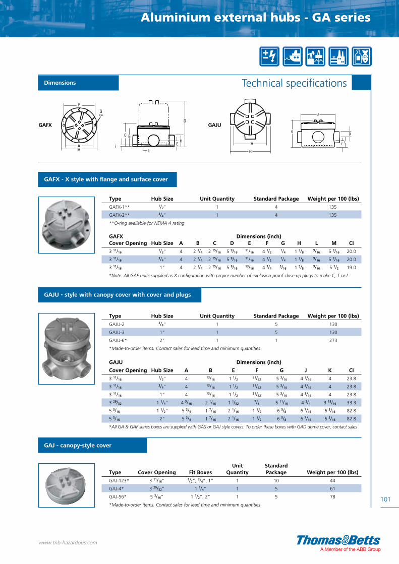
Aluminium external hubs - GA series
101
www.tnb-hazardous.comA Member of the ABB Group
GAFX - X style with flange and surface cover
Type Hub Size Unit Quantity Standard Package Weight per 100 (lbs)
GAFX-1** 1/2” 1 4 135
GAFX-2** 3/4” 1 4 135
**O-ring available for NEMA 4 rating
GAJU - style with canopy cover with cover and plugs
Type Hub Size Unit Quantity Standard Package Weight per 100 (lbs)
GAJU-2 3/4” 1 5 130
GAJU-3 1” 1 5 130
GAJU-6* 2” 1 1 273
*Made-to-order items. Contact sales for lead time and minimum quantities
GAJ - canopy-style cover
Unit StandardType Cover Opening Fit Boxes Quantity Package Weight per 100 (lbs)
GAJ-123* 3 11/16” 1/2”, 3/4”, 1” 1 10 44
GAJ-4* 3 29/32” 1 1/4” 1 5 61
GAJ-56* 5 3/16” 1 1/2”, 2” 1 5 78
*Made-to-order items. Contact sales for lead time and minimum quantities
Technical specifications
GAFX Dimensions (inch)Cover Opening Hub Size A B C D E F G H L M CI
3 11/16 1/2” 4 2 1/4 2 15/16 5 9/16 11/16 4 1/2 1/4 1 3/8 9/16 5 3/16 20.0
3 11/16 3/4” 4 2 1/4 2 15/16 5 9/16 11/16 4 1/2 1/4 1 3/8 9/16 5 3/16 20.0
3 11/16 1” 4 2 1/4 2 15/16 5 9/16 13/16 4 3/4 5/16 1 5/8 9/16 5 1/2 19.0
*Note: All GAF units supplied as X configuration with proper number of explosion-proof close-up plugs to make C, T or L
GAJU Dimensions (inch)
Cover Opening Hub Size A B E F G J K CI
3 11/16 1/2” 4 13/16 1 1/2 31/32 5 3/16 4 3/16 4 23.8
3 11/16 3/4” 4 13/16 1 1/2 31/32 5 3/16 4 3/16 4 23.8
3 11/16 1” 4 13/16 1 1/2 31/32 5 3/16 4 3/16 4 23.8
3 29/32 1 1/4” 4 5/16 2 1/16 1 1/32 7/8 5 11/16 4 3/4 3 15/16 33.3
5 3/16 1 1/2” 5 3/4 1 7/16 2 1/16 1 1/2 6 5/8 6 7/16 6 3/16 82.8
5 3/16 2” 5 3/4 1 7/16 2 1/16 1 1/2 6 5/8 6 7/16 6 3/16 82.8
*All GA & GAF series boxes are supplied with GAS or GAJ style covers. To order these boxes with GAD dome cover, contact sales
F
A
GDIA
M
C B
iL
D
HE
K
J
Dimensions whenGAJ cover is used
A
G
K
J
D
EF
GAFX GAJU
Dimensions
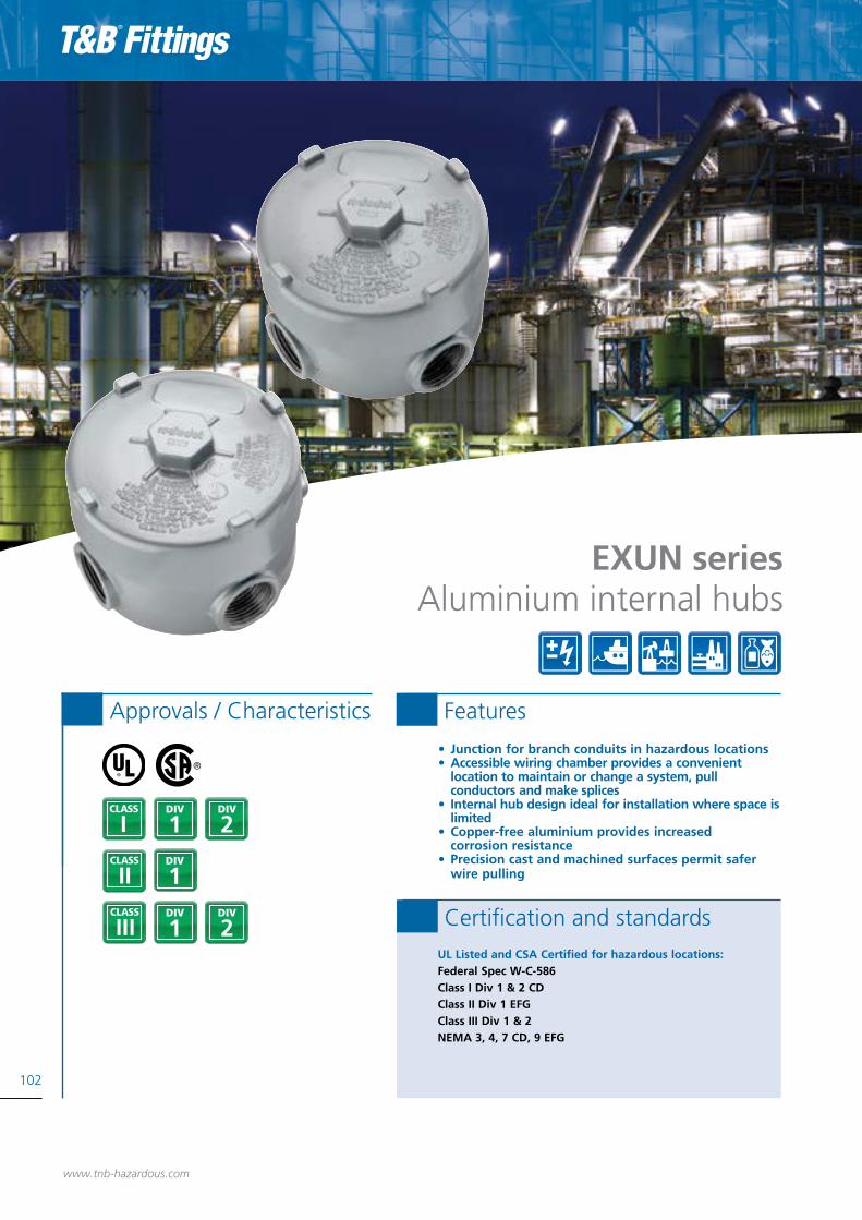
102
• Junction for branch conduits in hazardous locations• Accessible wiring chamber provides a convenient location to maintain or change a system, pull conductors and make splices• Internal hub design ideal for installation where space is
limited• Copper-free aluminium provides increased corrosion resistance• Precision cast and machined surfaces permit safer wire pulling
1DIV
2DIV
I
1DIV
Approvals / Characteristics Features
EXUN seriesAluminium internal hubs
UL Listed and CSA Certified for hazardous locations:Federal Spec W-C-586 Class I Div 1 & 2 CD Class II Div 1 EFGClass III Div 1 & 2NEMA 3, 4, 7 CD, 9 EFG
Certification and standards
www.tnb-hazardous.com
1DIV
2DIV

Aluminium internal hubs - EXUN series
103
www.tnb-hazardous.comA Member of the ABB Group
Technical specificationsDimensions
Copper-free aluminium
Internal hub design
Smooth conduit stops
Precision machined threads
Internal ground
boss and Die-cast lugs
EXUN - 5-hole aluminium box
EXUN - 4-hole aluminium box
Type Hub Size Description Unit Quantity Standard Package Weight per 100 (lbs)
EXUN-1 1/2” (5) Outlets 1 5 140
EXUN-2 3/4” with (3) Close-Up Plugs 1 5 140
EXUN-3 1” with (3) Close-Up Plugs 1 5 140
Type Hub Size Description Unit Quantity Standard Package Weight per 100 (lbs)
EXUN-11 1/2” (4) Outlets 1 5 140
EXUN-22 3/4” with (2) Close-Up Plugs 1 5 –
Size rangeAll sizes are listed in the tables on each page for each cat. no.
MaterialsDie-cast aluminium alloy A360 with less than.004 copper content (copper-free)
FinishAluminium lacquer finish
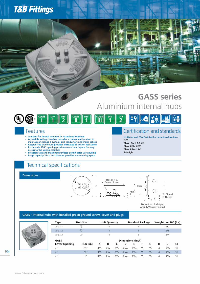
104
www.tnb-hazardous.com
GASS seriesAluminium internal hubs
2DIV
1DIV
I 1DIV
1DIV
2DIV
Technical specifications
“A” Thread (7 Places)
D
C
H dia.
G
Dimensions of all styles when GASS cover is used
#10–32 X 3⁄8 Ground Screw
TYP.J
FEG
A
CB
DH dia.
GASS - internal hubs with installed green ground screw, cover and plugs
Type Hub Size Unit Quantity Standard Package Weight per 100 (lbs)
GASS-1 1/2” 1 5 282
GASS-2 3/4” 1 5 278
GASS-3 2” 1 5 274
GASS Dimensions (inch)Cover Opening Hub Size A B C D E F G H J CI
4” 1/2” 45/8 23/8 33/8 23/16 23/16 1/2 3/4 4 25/8 31
4” 3/4” 45/8 23/8 33/8 23/16 23/16 1/2 3/4 4 25/8 31
4” 1” 45/8 23/8 33/8 23/16 23/16 1/2 3/4 4 25/8 31
Dimensions
• Junction for branch conduits in hazardous locations• Accessible wiring chamber provides a convenient location to maintain or change a system, pull conductors and make splices• Copper-free aluminium provides increased corrosion resistance• Extra-wide 33⁄4” opening provides more hand space for easy access to the wiring chamber• Precision cast and machined surfaces permit safer wire pulling • Large capacity 31-cu.-in. chamber provides more wiring space
UL Listed and CSA Certified for hazardous locations:NEC Class I Div 1 & 2 CD Class II Div 1 EFGClass III Div 1 & 2Raintight
Features Certification and standards

105
www.tnb-hazardous.comA Member of the ABB Group
GUPExplosion-proof enclosure
2DIV
1DIV
I 1DIV
1DIV
2DIV
GUP - explosion-proof enclosure
• Compact design• O-ring gasket standard for raintight applications• Supplied with conduit plugs – three plugs for GUP215-TB – seven plugs for GUP214-TB
UL886 Listed and CSA Standard C22.2 Certified for hazardous locations:Class I Div 1 & 2 CD Class II Div 1 EFGClass III Div 1 & 2NEMA 3, 4, 7 CD, 9 EFG
Features Certification and standards
Technical Specifications
Dimensions
4.375111.13
3.79596.39
1.1501.870
StandardType Description Package qty
GUP214-TB Junction box — 10 hubs (3⁄4” NPT): (2) in top, (2) in bottom, (1) in each side, (4) in the back 1
GUP215-TB Junction box — (6) hubs (3⁄4” NPT): (2) in top, (2) in bottom, (1) in each side 1

106
www.tnb-hazardous.com
• Junction for branch conduits• Accessible wiring chamber provides a convenient location to pull conductors and make splices• 31 cu. in. capacity• Copper-free* aluminium provides increased corrosion resistance• Precision cast and machined surfaces permit safer wire pulling• Precision NPT threaded hubs enable trouble-free field installation for rigid or IMC conduit
1DIV
2DIV
I
1DIV
Approvals / Characteristics Features
LB and T styleAluminium conduit body
UL Listed and CSA Certified for hazardous locations:NEC Class I Div 1 & 2 CD Class II Div 1 EFGClass III Div 1 & 2NEMA 3, 4, 7 CD, 9 EFG
Certification and standards1DIV
2DIV
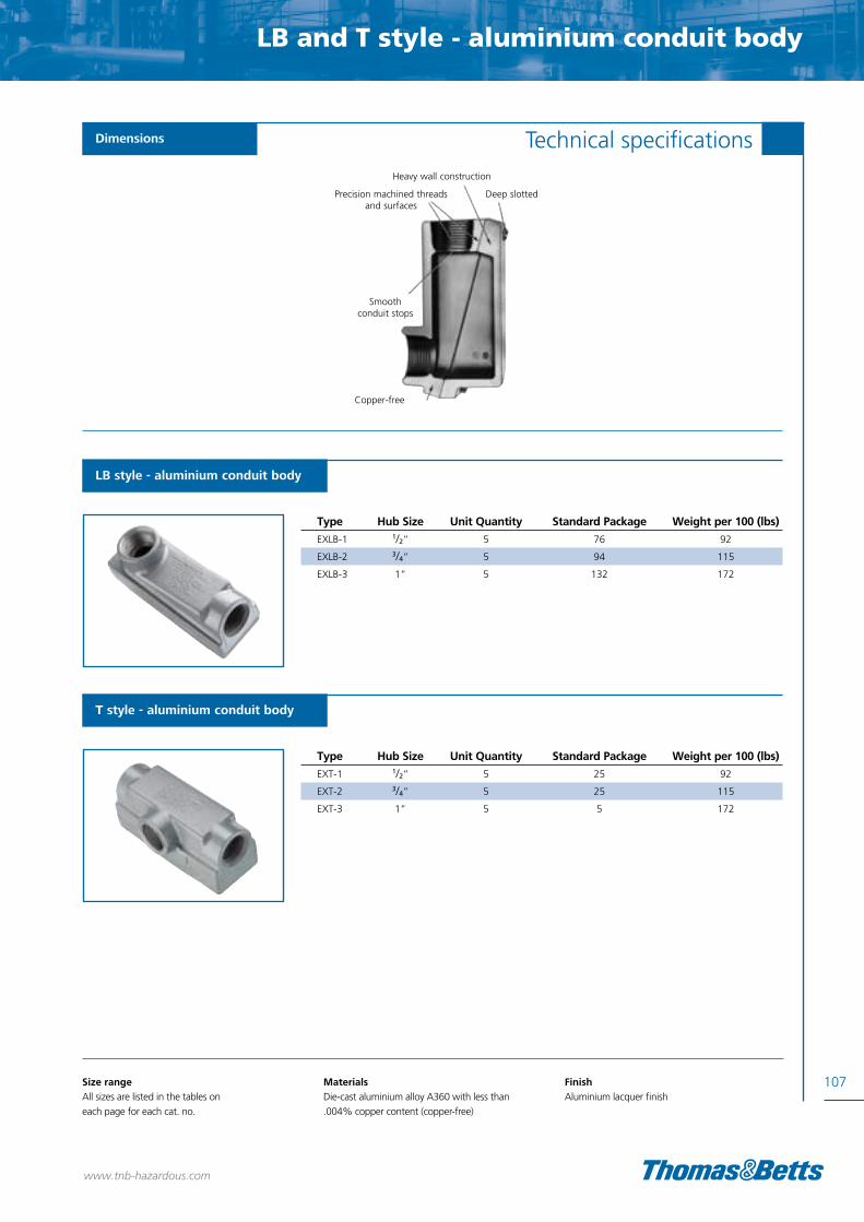
LB and T style - aluminium conduit body
107
www.tnb-hazardous.com
Technical specificationsDimensions
LB style - aluminium conduit body
T style - aluminium conduit body
Type Hub Size Unit Quantity Standard Package Weight per 100 (lbs)
EXLB-1 1/2” 5 76 92
EXLB-2 3/4” 5 94 115
EXLB-3 1” 5 132 172
Type Hub Size Unit Quantity Standard Package Weight per 100 (lbs)
EXT-1 1/2” 5 25 92
EXT-2 3/4” 5 25 115
EXT-3 1” 5 5 172
Size rangeAll sizes are listed in the tables on each page for each cat. no.
MaterialsDie-cast aluminium alloy A360 with less than.004% copper content (copper-free)
FinishAluminium lacquer finish
Copper-free
Smooth conduit stops
Precision machined threads and surfaces
Heavy wall construction
Deep slotted

• Protect conductors in threaded rigid conduit• Act as pulling and splice fittings• Interconnect lengths of conduit• Change direction of conduit• Tapered threaded hubs for ground continuity• Smooth integral hub bushings to protect conductor
insulation when pulling• Five different hub arrangements• Accurately machined body with blind tapped screw
holes
108
1DIV
2DIV
I
1DIV
Approvals / Characteristics Features
OE seriesIron conduit outlet bodies
UL Listed and CSA Certified for hazardous locations:Class I Div 1 & 2 CD Class II Div 1 EFGClass III Div 1 & 2NEMA 3, 4, 7 CD, 9 EFG
Certification and standards
www.tnb-hazardous.com
1DIV
2DIV

Iron conduit outlet bodies - OE series
Dimensions (Inches)
Type Hub Size A B C D E F
OEC1-TB 1/2” 4.06 1.62 1.90 0.69 0.88 0.63
OEC2-TB 3/4” 4.35 1.88 2.19 0.69 0.88 0.76
OET1-TB 1/2” 4.06 1.62 1.90 0.69 0.88 0.63
OET2-TB 3/4” 4.35 1.88 2.19 0.69 0.88 0.76
OELL1-TB 1/2” 4.06 1.62 1.90 0.69 0.88 0.63
OELL2-TB 3/4” 4.35 1.88 2.19 0.69 0.88 0.76
OELR1-TB 1/2” 4.06 1.62 1.90 0.69 0.88 0.63
OELR2-TB 3/4” 4.35 1.88 2.19 0.69 0.88 0.76
OELB1-TB 1/2” 4.06 1.62 1.90 0.69 0.88 0.63
OELB2-TB 3/4” 4.35 1.88 2.19 0.69 0.88 0.76
109Size rangeAll sizes are listed in the tables on each page for each cat. no.
MaterialsBodies: Grade 60-45-10 ductile iron (Complies with ASTM standard A536)
FinishElectrogalvanized and aluminium acrylic paint
Technical specificationsDimensions
www.tnb-hazardous.comA Member of the ABB Group
A
C
B
F
D
D
E
E
E

110
www.tnb-hazardous.com
• Make 90° bends in conduit systems where space is limited• Act as pull outlets• Provide access to conductors for maintenance and future system changes• Maximum volume for bends within a compact overall size• Screw on cover for ease of installation and removal• Cover opening on an angle, permitting conductors to be pulled straight through either hub• Tapered threaded hubs and integral bushing for rigid
threaded conduit
1DIV
2DIV
I
1DIV
Approvals / Characteristics Features
Capped elbowsIron and aluminium - female to female
UL Listed and CSA Certified for hazardous locations:Class I Div 1 & 2 CD Class II Div 1 EFGClass III Div 1 & 2NEMA 3, 4, 7 CD, 9 EFG
Certification and standards1DIV
2DIV

Iron and aluminium capped elbows - female to female
111
www.tnb-hazardous.com
Technical specificationsDimensions
LBY - capped iron elbow - female to female
GYF - capped aluminium elbow - female to female
Dimensions (in) Throat Dimensions (in)
Type Hub Size A B min. max.
LBY15-TB 1/2” 2 9/16 2 0.570 0.610
LBY25-TB 3/4” 2 13/16 2 1/4 0.755 0.810
LBY35-TB 1” 3 3/32 2 1/2 0.955 1.035
LBY45-TB 1 1/4” 3 3/4 2 15/16 1.260 1.360
LBY55-TB 1 1/2” 4 1/4 3 3/8 1.470 1.590
LBY65-TB 2” 5 1/2 4 1.880 2.047
Type Hub Size Unit Quantity Standard Package Weight per 100 (lbs)
GYF-1 1/2” 10 50 23
GYF-2 3/4” 5 25 40
GYF-3 1” 5 25 60
GYF-4 * 11/4” 2 10 95
GYF-5 11/2” 2 10 95
*Made-to-order items. Consult factory for lead time and minimum quantities.make C, T or L
Size rangeAll sizes are listed in the tables on each page for each cat. no.
Materials LBY ductile IronGYF copper free aluminium
A
BØ
B
A
BØ
B

112
www.tnb-hazardous.com
• RE and REC reducers are used in threaded heavy wall conduit systems• RE reduces conduit hubs to a smaller size• REC connects two different sizes of conduit together or is used to replace a coupling and reducer in an installation• PLG plugs are used for closing threaded conduit hubs• All hubs have NPT threads with a minimum of five
full threads and integral bushing for preventing damage to wires
1DIV
2DIV
I
1DIV
Approvals / Characteristics Features
Reducers, plugs and adapters
UL Listed and CSA Certified for hazardous locations:UL: 886CSA: C22.2 No.30Class I, Div. 1 & 2, Groups A, B, C, DClass II, Div. 1, Groups E, F, GClass III, Div. 1 & 2
Certification and standards1DIV
2DIV

Reducers, plugs and adapters
Technical specifications
Reducing bushings
REC series reducers
Funnel-shaped reducers for hazardous and non-hazardous locations
Recessed plugs
With flush head for hazardous and non-hazardous locations
Aluminium recessed plugs
With flush head for hazardous and non-hazardous locations
Type A Male (NPT) B Female (NPT)
RE21-TB 3/4” 1/2”
RE31-TB 1” 1/2”
RE32-TB 1” 3/4”
RE41-TB 11/4” 1/2”
RE42-TB 11/4” 3/4”
RE43-TB 11/4” 1”
RE51-TB 11/2” 1/2”
RE52-TB 11/2” 3/4”
RE53-TB 11/2” 1”
RE54-TB 11/2” 11/4”
RE61-TB 2” 1/2”
RE62-TB 2” 3/4”
RE63-TB 2” 1”
RE64-TB 2” 11/4”
RE65-TB 2” 11/2”
Type A Male (NPT)
PLG1-TB 1/2”
PLG2-TB 3/4”
PLG3-TB 1”
PLG4-TB 11/4”
PLG5-TB 11/2”
PLG6-TB 2”
PLG7-TB 21/2”
PLG8-TB 3”
PLG9-TB 31/2”
PLG10-TB 4”
Type A Male (NPT)
XPLG-1* 1/2”
XPLG-2* 3/4”
XPLG-3* 1”
XPLG-4** 11/4”
XPLG-5** 11/2”
XPLG-6** 2”
Made-to-order items. Consult factory for lead time and minimum quantities. ** Not UL Listed and not approved for use in hazardous locations. ** UL Listed E 34438.
Type A (NPT) B (NPT) C
REC21-TB 3/4 1/2 -14 17/8
REC31-TB 1 1/2 -14 2
REC32-TB 1 1/2 -14 2
Type A Male (NPT) B Female (NPT)
RE73-TB 21/2” 1”
RE74-TB 21/2” 11/4”
RE75-TB 21/2” 11/2”
RE76-TB 21/2” 2”
RE83-TB 3” 1”
RE84-TB 3” 11/4”
RE85-TB 3” 11/2”
RE86-TB 3” 2”
RE87-TB 3” 21/2”
RE96-TB 31/2” 2”
RE97-TB 31/2” 21/2”
RE98-TB 31/2” 3”
RE106-TB 4” 2”
RE107-TB 4” 21/2”
RE108-TB 4” 3”
B
A
A
A
C
113
www.tnb-hazardous.comA Member of the ABB Group
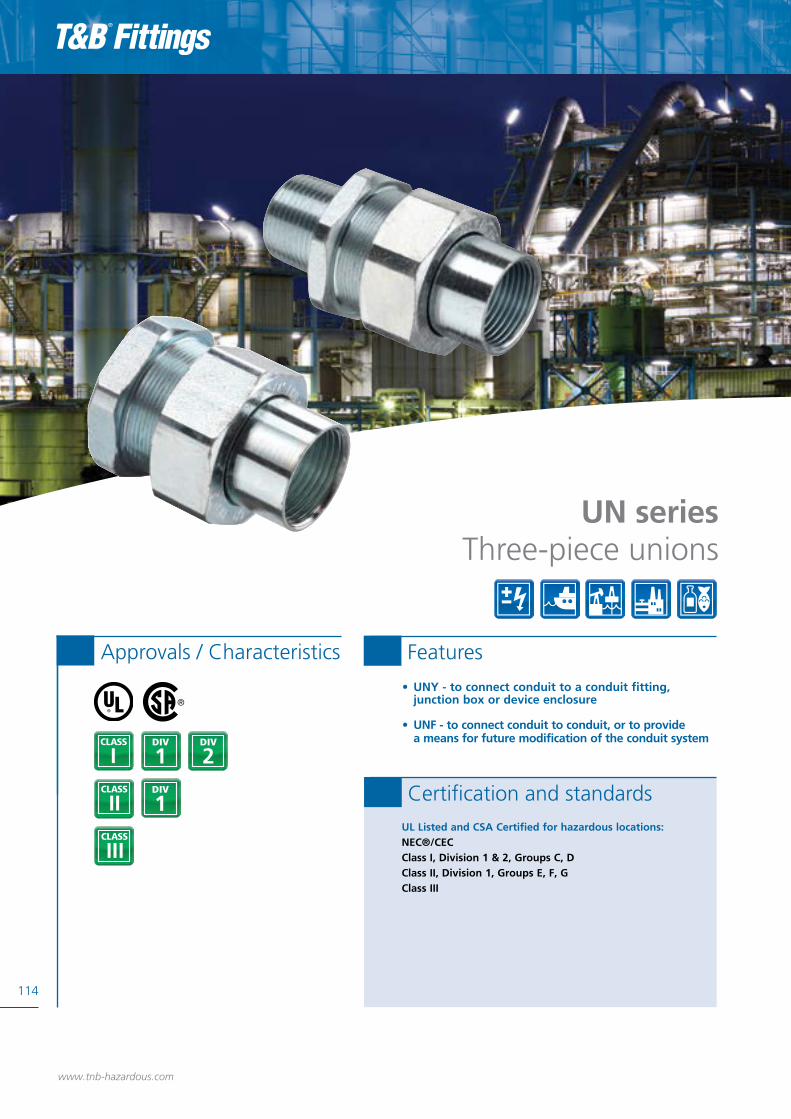
• UNY - to connect conduit to a conduit fitting, junction box or device enclosure
• UNF - to connect conduit to conduit, or to provide a means for future modification of the conduit system
114
1DIV
2DIV
I
1DIV
Approvals / Characteristics Features
UN seriesThree-piece unions
UL Listed and CSA Certified for hazardous locations:NEC®/CECClass I, Division 1 & 2, Groups C, DClass II, Division 1, Groups E, F, GClass III
Certification and standards
www.tnb-hazardous.com
1DIV
2DIV

Three-piece unions - UN series
115
Technical specifications
www.tnb-hazardous.comA Member of the ABB Group
UNY - male unions - for hazardous and non-hazardous locations
UNF - female unions - for hazardous and non-hazardous locations
Type Trade Size Overall Length/inches Overall Dia./inches
UNY105-TB 1/2” 225/64 11/2
UNY205-TB 3/4” 27/16 113/16
UNY305-TB 1” 23/4 2
UNY405-TB 11/4” 31/16 23/4
UNY505-TB 11/2”” 35/8 31/16
UNY605-TB 2” 31/2 313/16
UNY705-TB 21/2”” 413/16 45/16
UNY805-TB 3” 511/32 51/16
UNY905-TB 31/2”” 51/2 511/16
UNY1005-TB 4” 55/8 63/16
Type Trade Size Overall Length/inches Overall Dia./inches
UNF105-TB† 1/2” 17/8 11/2
UNF205-TB† 3/4” 21/8 113/16
UNF305-TB† 1” 25/32 2UNF405-TB†† 11/4” 21/4 23/4
UNF505-TB†† 11/2”” 23/4 31/16
UNF605-TB††† 2” 21/2 313/16
UNF705-TB††† 21/2”” 31/2 45/16
UNF805-TB††† 3” 4 51/16
UNF905-TB††† 31/2”” 45/32 511/16
UNF1005-TB††† 4” 41/4 63/16
† Steel † † Forged steel † † † Malleable iron
Dimensions
UNY UNF
Length Length
Length Length
Max. Dia. Max. Dia.Max. Dia. Max. Dia.
Size rangeAll sizes are listed in the tables on each page for each cat. no.
MaterialsSteel, Iron alloy, malleable iron
FinishElectrogalvanized with chromate treatmentand aluminium acrylic paint

116
www.tnb-hazardous.com
• Used as connecting elements between enclosures, fittings or boxes that permit future changes to the system in both hazardous and non-hazardous areas• Copper-free* aluminium provides increased corrosion resistance• Precision cast and machined surfaces permit safer wire pulling• Precision NPT threaded hubs allow trouble-free field installation for rigid or IMC conduit• Clear UL, CSA and cubic content markings speed
approval by inspectors• Unique concentric ring design ensures critical flame path control
1DIV
2DIV
I
1DIV
Approvals / Characteristics Features
EX seriesAluminium three-piece unions
UL Listed and CSA Certified for hazardous locations:Federal Spec W-C-586Class I, Div. 1 & 2, Groups C, DClass II, Div. 1, Groups E, F, GClass III, Div. 1 & 2NEMA 3, 4, 7 CD, 9 EFG
Certification and standards1DIV
2DIV

Aluminium three-piece unions - EX series
117
www.tnb-hazardous.com
Technical specificationsDimensions
EXFU - female-to-female unions
EXMU - male-to-female unions
Throat Dim.Type Hub Size Unit Quantity Standard Package Weight per 100 (lbs)
EXFU-1 1/2” 5 25 24
EXFU-2 3/4” 5 25 33
EXFU-3 1” 5 25 42
EXFU-4 11/4” 5 25 53
EXFU-5 11/2” 5 25 68
EXFU-6* 2” 2 10 130
EXFU-8* 3” 1 5 310
EXFU-9* 31/2” 1 5 340
EXFU-10* 4” 1 1 374
*Made-to-order items. Consult factory for lead time and minimum quantities.make C, T or L
Type Hub Size Unit Quantity Standard Package Weight per 100 (lbs)
EXMU-1 1/2” 5 25 24
EXMU-2 3/4” 5 25 35
EXMU-3 1” 5 25 45
*Made-to-order items. Consult factory for lead time and minimum quantities.make C, T or L
Size rangeAll sizes are listed in the tables on each page for each cat. no.
Materials Die-cast aluminium alloy A360 with less than .004 copper content (copper-free)EXMU nipples are galvanized steel
FinishAluminium lacquer finish
Precision machined threads
Unique concentric ring
design
Smooth conduit stops
Copper-free aluminium
A Member of the ABB Group

118
www.tnb-hazardous.com
• Drain to provide continuous, automatic drainage of condensate• Large openings with threaded closures to provide easy access to conduit hubs for making dams• Integral bushings to protect conductor insulation from damage• Tapered-tapped hubs to ensure ground continuity standard materials
1DIV
2DIV
I
1DIV
Approvals / Characteristics Features
EYD and ECD seriesDrain seals and breathers
UL Listed and CSA Certified for hazardous locations:EYD11 — 31-TBClass I, Division 1 & 2, Groups A, B, C, D; Class II, Division 1,Groups E, F, G; Class IIIEYD41 — 101-TBClass I, Division 1 & 2, Groups C, D; Class II, Division 1, Groups E, F, GClass II, Division 2, Groups F, GClass IIIUL Standard: 886CSA Standard: C22.2
Certification and standards
1DIV
2DIV

Drain seals and breathers - EYD and ECD series
119
www.tnb-hazardous.com
Technical specificationsDimensions
EYD - drain seals
ECD - drain breathers
Dimensions inchesType Hub Size A B Turning Radius
EYD11-TB 1/2” 3.81 1.50 1.75
EYD21-TB 3/4” 4.08 1.75 1.98
EYD31-TB 1” 4.85 2.19 2.19
EYD41-TB 11/4” 5.00 2.25 1.80
EYD51-TB 11/2” 5.44 2.44 2.00
EYD61-TB 2” 6.25 3.00 2.32
EYD71-TB 21/2” 7.50 3.50 2.69
EYD81-TB 3” 8.50 4.25 3.15
EYD91-TB 31/2” 9.19 4.75 3.38
EYD101-TB 4” 9.75 5.25 3.64
Dimensions inchesType Hub Size B
ECD15 1/2” .975
ECD384 3/8” .407
ECD284 1/4” .327
Size rangeAll sizes are listed in the tables on each page for each cat. no.
MaterialsBodies and drain covers - gray iron alloy and/orductile ironClosure for drain - copper-free aluminium or ductile ironSmall closure plug - gray iron alloy and/or steelDrain — stainless steel Removable nipples - steel
FinishGray iron alloy and ductile iron - electrogalvanizedand aluminium acrylic paintCopper-free aluminium - naturalStainless steel - naturalSteel - electrogalvanized
B
EYD 1⁄2" – 1"
Turning Radius
A
Turning Radius
A
B
B
A Member of the ABB Group

120
www.tnb-hazardous.com
• All hubs have a minimum of five full threads, integral bushings to protect conductor insulation from damage and large access openings for easier packing of sealing medium• Seals are approved to be used with Crouse-Hinds® sealing compound and fiber standard materials1
DIV
2DIV
I
1DIV
Approvals / Characteristics Features
EYS seriesSealing fittings
UL Listed and CSA Certified for hazardous locations:UL886CSA: C22.2 No. 30EYS seals are approved to be used with Crouse-Hinds® Chico® A compound and Chico® X fiberEYS1-3TB: Cl. I, Div. 1 & 2, Groups A, B, C, DEYS4-5TB: Cl. I, Div. 1 & 2, Groups C, DEYS11-31TB: Cl. I, Div. 1 & 2, Groups A, B, C, DClass II, Div. 1, Groups E, F, GClass IIIEYS41-101TB: Cl. I, Div. 1 & 2, Groups C, DClass II, Div. 1, Groups E, F, GClass IIINEMA 3, 4, 7 CD, 9 EFG
Certification and standards
1DIV
2DIV

Sealing fittings - EYS series
121
www.tnb-hazardous.com
Technical specificationsDimensions
Vertical only
Horizontal/vertical
Size rangeAll sizes are listed in the tables on each page for each cat. no.
MaterialsBodies: Ductile IronPlugs: Gray IronNipples: Steel, supplied with EYS fittings
FinishBodies: Zinc-plated with aluminium acrylic paintPlugs: Zinc-plated with aluminium acrylic paintNipples: Zinc-plated
EYS11-TB – EYS101-TB
B
A
EYS1-TB – EYS5-TB
Dimensions inchesType Hub Size A B C Turning Radius
EYS1-TB 1/2” 3.31 1.25 1.50 1.66”
EYS2-TB 3/4” 3.65 1.50 1.75 1.96”
EYS3-TB 1” 4.25 1.75 2.19 2.40”
EYS4-TB 11/4” 5.00 2.25 2.45 3.11”
EYS5-TB 11/2” 5.69 2.45 3.00 3.62”
Dimensions inchesType Hub Size A B C Turning Radius
EYS11-TB 1/2” 35/8 11/4 – 13/32”
EYS21-TB 3/4” 321/32 11/2 – 11/4”
EYS31-TB 1” 41/4 13/4 – 119/32”
EYS41-TB 11/4” 5 21/4 – 113/16”
EYS51-TB 11/2” 57/16 27/16 – 2”
EYS61-TB 2” 61/4 3 – 25/16”
EYS71-TB 21/2” 71/2 31/2 – 29/16”
EYS81-TB 3” 81/2 41/4 – 33/32”
EYS91-TB 31/2” 93/16 43/4 – 33/8”
EYS101-TB 4” 93/4 51/4 – 317/32”
Crouse-Hinds® and Chico® are trademarks of Cooper Industries, Inc.
C
A
B
A Member of the ABB Group

122
www.tnb-hazardous.com
• Limits flames and/or explosions to area within electrical system where they originate• Limits pressure piling• Copper-free* aluminium provides increased corrosion resistance• Precision cast and machined surfaces permit safer wire pulling• Large opening provides maximum working room for creating dam and seal pouring to speed up installation• Compact design permits close construction of parallel conduit runs
1DIV
2DIV
I
1DIV
Approvals / Characteristics Features
UL Listed and CSA Certified for hazardous locations:Federal Spec W-C-586Class I, Div. 1 & 2, Groups C, DClass II, Div. 1, Groups E, F, GClass III, Div. 1 & 2NEMA 3, 4, 7 CD, 9 EFG
Certification and standards1DIV
2DIV
EYVF and EVHF seriesSealing fittings

Sealing fittings - EYVF and EVHF series
123
www.tnb-hazardous.com
Technical specificationsDimensions
Size rangeAll sizes are listed in the tables on each page for each cat. no.
MaterialsSealing fittings: Die-cast aluminium alloy A360with less than .004 copper content (copper-free)Sealing cementFiber: Flame-retardant Kaowool type A fiber
FinishAluminium lacquer finish
EYVF - vertical sealing fittings
EVHF - vertical/horizontal sealing fittings
Throat Dim.Type Hub Size Unit Quantity Standard Package Weight per 100 (lbs)
EYVF-1* 1/2” 5 25 25
EYVF-2* 3/4” 5 25 54
EYVF-3* 1” 5 25 100
EYVF-11 1/2” 10 50 35
EYVF-22 3/4” 10 50 40
EYVF-33 1” 4 20 60
*Packaged with an adequate amount of sealing compound and plugs installed.
Type Hub Size Unit Quantity Standard Package Weight per 100 (lbs)
EVHF-1 1/2” 10 50 41
EVHF-2 3/4” 5 25 50
EVHF-3 1” 5 25 60
EVHF-4 11/4” 4 20 70
EVHF-5 11/2” 1 5 60
EVHF-6 2” 1 1 125
EVHF-7* 21/2” 1 1 150
EVHF-8* 31/2” 1 1 300
*Made-to-order items. Consult factory for lead time and minimum quantities
Precision machined threads
Large aperture for easy installation
Copper-free aluminium
Smooth conduit stops
A Member of the ABB Group

• Can be used on T&B EYV, EVH series fittings only• T&B Red•Dot® sealing cement is used for making seals in sealing fittings. The insulation in the conductors sealed in the cement may be approved thermoplastic or rubber, with or without lead covering. The sealing cement should not be used for insulating• T&B Red•Dot® sealing cement is not affected by gasoline, alcohol, acetone, ether, naptha, petroleum, benzol or lacquer solvent.
124
1DIV
2DIV
I
1DIV
Approvals / Characteristics Features
Sealing cement and fiberfor T&B® sealing fittings
UL Listed and CSA Certified for hazardous locations:Class I, Div. 1 & 2, Groups C, DClass II, Div. 1, Groups E, F, GClass III, Div. 1 & 2NEMA 3, 4, 7 CD, 9 EFG
Certification and standards
www.tnb-hazardous.com
1DIV
2DIV
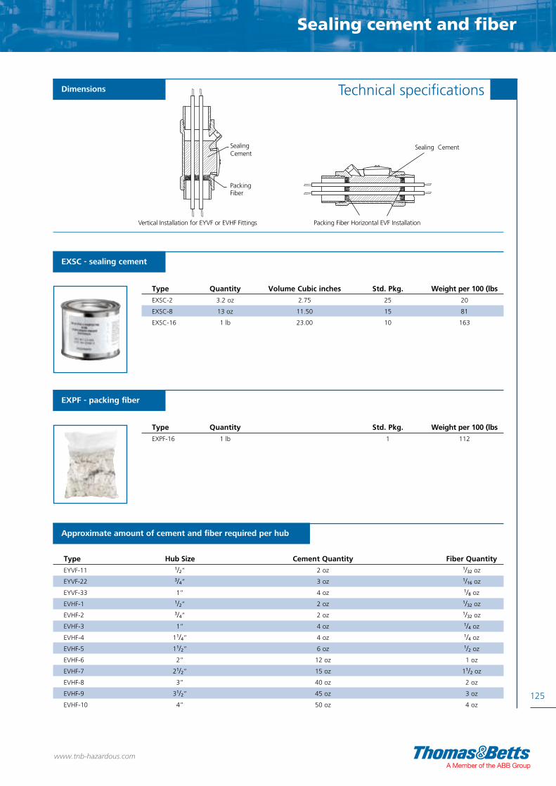
Sealing cement and fiber
125
Technical specifications
www.tnb-hazardous.comA Member of the ABB Group
EXSC - sealing cement
EXPF - packing fiber
Type Quantity Volume Cubic inches Std. Pkg. Weight per 100 (lbs
EXSC-2 3.2 oz 2.75 25 20
EXSC-8 13 oz 11.50 15 81
EXSC-16 1 lb 23.00 10 163
Type Quantity Std. Pkg. Weight per 100 (lbs
EXPF-16 1 lb 1 112
Dimensions
Approximate amount of cement and fiber required per hub
Type Hub Size Cement Quantity Fiber Quantity
EYVF-11 1/2” 2 oz 1/32 oz
EYVF-22 3/4” 3 oz 1/16 oz
EYVF-33 1” 4 oz 1/8 oz
EVHF-1 1/2” 2 oz 1/32 oz
EVHF-2 3/4” 2 oz 1/32 oz
EVHF-3 1” 4 oz 1/4 oz
EVHF-4 11/4” 4 oz 1/4 oz
EVHF-5 11/2” 6 oz 1/2 oz
EVHF-6 2” 12 oz 1 oz
EVHF-7 21/2” 15 oz 11/2 oz
EVHF-8 3” 40 oz 2 oz
EVHF-9 31/2” 45 oz 3 oz
EVHF-10 4” 50 oz 4 oz
Packing Fiber
Vertical Installation for EYVF or EVHF Fittings
Sealing Cement
Packing Fiber Horizontal EVF Installation
Sealing Cement

26126
www.tnb-hazardous.com
Thread convertors, stopping plugsand accessories
Thread convertors, stopping plugsThread convertors, stopping plugsThread convertors,
and accessoriesstopping plugsand accessoriesstopping plugsThread convertors, stopping plugsand accessories

127
www.tnb-hazardous.comA Member of the ABB Group
Thread convertors, stopping plugs and accessories

• Thread Convertors provide a method of
matching threadforms on hazardous location
equipment whilst ensuring the integrity and approval
of the installation is maintained
Approvals / Characteristics Features
Thread convertorsEnlargers, reducers and convertors
Certification Standard: ATEX: Baseefa07 ATEX 0247X, IECEx: IECEx BAS07.0090XGOST R: POCC GB.ГГ05.B03850INMETRO: TÜV 11.0339XEx d IIC GbEx e IIC GbEx tb IIIC DbClass I Div1 ABCD, Class II Div1 EFG (does not include M16 & 3/8”NPT or unplated brass products)Approved to UL 1203Approved to CSA C22.2 No.60079-04Approved to C22.2 No.60079-1
Certification & Standards
128
1DIV
I 1DIV
www.tnb-hazardous.com
b

Male
External Metric Female Internal ThreadThread M16 M20 M25 M32 M40 M50 M63 M75
M16 EX/M16-M20/E EX/M16-M25/E
M20 EX/M20-M16/R EX/M20-M25/E EX/M20-M32/E
M25 EX/M25-M16/R EX/M25-M20/R EX/M25-M32/E EX/M25-M40/E
M32 EX/M32-M16/R EX/M32-M20/R EX/M32-M25/R EX/M32-M40/E EX/M32-M50/E
M40 EX/M40-M16/R EX/M40-M20/R EX/M40-M25/R EX/M40-M32/R EX/M40-M50/E EX/M40-M63/E
M50 EX/M50-M16/R EX/M50-M20/R EX/M50-M25/R EX/M50-M32/R EX/M50-M40/R EX/M50-M63/E EX/M50-M75/E
M63 EX/M63-M16/R EX/M63-M20/R EX/M63-M25/R EX/M63-M32/R EX/M63-M40/R EX/M63-M50/R EX/M63-M75/E
M75 EX/M75-M16/R EX/M75-M20/R EX/M75-M25/R EX/M75-M32/R EX/M75-M40/R EX/M75-M50/R EX/M75-M63/R
NPT 3/8 EX/038-M16/TC
NPT 1/2 EX/050-M16/TC EX/050-M20/TC EX/050-M25/TC
NPT 3/4 EX/075-M16/TC EX/075-M20/TC EX/075-M25/TC EX/075-M32/TC
NPT 1 EX/100-M16/TC EX/100-M20/TC EX/100-M25/TC EX/100-M32/TC EX/100-M40/TC
NPT 1 1/4 EX/125-M16/TC EX/125-M20/TC EX/125-M25/TC EX/125-M32/TC EX/125-M40/TC EX/125-M50/TC
NPT 1 1/2 EX/150-M16/TC EX/150-M20/TC EX/150-M25/TC EX/150-M32/TC EX/150-M40/TC EX/150-M50/TC EX/150-M63/TC
NPT 2 EX/200-M16/TC EX/200-M20/TC EX/200-M25/TC EX/200-M32/TC EX/200-M40/TC EX/200-M50/TC EX/200-M63/TC
NPT 2 1/2 EX/250-M16/TC EX/250-M20/TC EX/250-M25/TC EX/250-M32/TC EX/250-M40/TC EX/250-M50/TC
NPT 3 EX/300-M16/TC EX/300-M20/TC EX/300-M25/TC EX/300-M32/TC EX/300-M40/TC EX/300-M50/TC EX/300-M75/TC
Enlargers, Reducers & Thread Convertors
129
Technical Specification
www.tnb-hazardous.comA Member of the ABB Group
* For nickel plated brass version, add N to the reference, e.g. EXN/M20-M16/R** For stainless steel 316 version, add S to the reference, e.g. EXS/M20-M16/RN.B. PG thread convertors available upon request.
* For nickel plated brass version, add N to the reference, e.g. EXN/M20-M16/R** For stainless steel 316 version, add S to the reference, e.g. EXS/M20-M16/RN.B. PG thread convertors available upon request.
Male
External NPT Female Internal ThreadThread NPT 1/2 NPT 3/4 NPT 1 NPT 1 1/4 NPT 1 1/2 NPT 2 NPT 2 1/2 NPT 3
M16 EX/M16-050/TC
M20 EX/M20-050/TC EX/M20-075/TC
M25 EX/M25-050/TC EX/M25-075/TC EX/M25-100/TC
M32 EX/M32-050/TC EX/M32-075/TC EX/M32-100/TC EX/M32-125/TC
M40 EX/M40-050/TC EX/M40-075/TC EX/M40-100/TC EX/M40-125/TC EX/M40-150/TC
M50 EX/M50-050/TC EX/M50-075/TC EX/M50-100/TC EX/M50-125/TC EX/M50-150/TC EX/M50-200/TC
M63 EX/M63-050/TC EX/M63-075/TC EX/M63-100/TC EX/M63-125/TC EX/M63-150/TC EX/M63-200/TC
M75 EX/M75-050/TC EX/M75-075/TC EX/M75-100/TC EX/M75-125/TC EX/M75-150/TC EX/M75-200/TC
NPT 1/2 EX/050-075/E
NPT 3/4 EX/075-050/R EX/075-100/E
NPT 1 EX/100-050/R EX/100-075/R EX/100-125/E
NPT 1 1/4 EX/125-050/R EX/125-075/R EX/125-100/R EX/125-150/E
NPT 1 1/2 EX/150-050/R EX/150-075/R EX/150-100/R EX/150-125/R EX/150-200/E
NPT 2 EX/200-050/R EX/200-075/R EX/200-100/R EX/200-125/R X/200-150/R
NPT 2 1/2 EX/250-050/R EX/250-075/R EX/250-100/R EX/250-125/R EX/250-150/R EX/250-200/R EX/250-300/E
NPT 3 EX/300-050/R EX/300-075/R EX/300-100/R EX/300-125/R EX/300-150/R EX/300-200/R EX/300-250/R
Enlargers, reducers and thread convertors

• For use in potentially explosive environments
• Manufactured from either brass, nickel plated brass
or stainless steel
Approvals / Characteristics Features
Standard Ex d stopping plug and tamperproof Ex d stopping plug
EC TYPE Examination Certificate:ATEX: Baseefa 08 ATEX 6324IECEx: IECEx BAS08.0109XGOST R: POCC GB.ГБ05.B03850INMETRO: TÜV 11.0093UL 1203 (Nickel Plated Brass and Stainless Steel only)Ex d I MbEx d IIC GbClass I Div 1 ABCDClass II Div 1 EFGTemperature: -60ºC to +130ºC
Certification & Standards
1DIV
I 1DIV
130
www.tnb-hazardous.com

Nickel Plated Thread SizeType - NPT NPT (inch)
EXN/038/TSP 3/8
EXN/050/TSP 1/2
EXN/075/TSP 3/4
EXN/100/TSP 1
EXN/125/TSP 11/4
EXN/150/TSP 11/2
EXN/200/TSP 2
Nickel Plated Thread SizeType - Metric Metric (mm)
EXN/M16/TSP 16
EXN/M20/TSP 20
EXN/M25/TSP 25
EXN/M32/TSP 32
EXN/M40/TSP 40
EXN/M50/TSP 50
EXN/M63/TSP 63
Nickel Plated Thread SizeType - NPT NPT (inch)
EXN/038/SP 3/8
EXN/050/SP 1/2
EXN/075/SP 3/4
EXN/100/SP 1
EXN/125/SP 11/4
EXN/150/SP 11/2
EXN/200/SP 2
Nickel Plated Thread SizeType - Metric Metric (mm)
EXN/M16/SP 16
EXN/M20/SP 20
EXN/M25/SP 25
EXN/M32/SP 32
EXN/M40/SP 40
EXN/M50/SP 50
EXN/M63/SP 63
131
Ex d Stopping Plugs
Technical SpecificationsStandard Exd stopping plug
Tamperproof Exd stopping plug
Stainless Steel Thread SizeType - NPT NPT (inch)
EXS/038/TSP 3/8
EXS/050/TSP 1/2
EXS/075/TSP 3/4
EXS/100/TSP 1
EXS/125/TSP 11/4
EXS/150/TSP 11/2
EXS/200/TSP 2
Stainless Steel Thread SizeType - Metric Metric (mm)
EXS/M16/TSP 16
EXS/M20/TSP 20
EXS/M25/TSP 25
EXS/M32/TSP 32
EXS/M40/TSP 40
EXS/M50/TSP 50
EXS/M63/TSP 63
Stainless Steel Thread SizeType - NPT NPT (inch)
EXS/038/SP 3/8
EXS/050/SP 1/2
EXS/075/SP 3/4
EXS/100/SP 1
EXS/125/SP 11/4
EXS/150/SP 11/2
EXS/200/SP 2
Stainless Steel Thread SizeType - Metric Metric (mm)
EXS/M16/SP 16
EXS/M20/SP 20
EXS/M25/SP 25
EXS/M32/SP 32
EXS/M40/SP 40
EXS/M50/SP 50
EXS/M63/SP 63
Brass Thread SizeType - NPT NPT (inch)
EX/038/TSP 3/8
EX/050/TSP 1/2
EX/075/TSP 3/4
EX/100/TSP 1
EX/125/TSP 11/4
EX/150/TSP 11/2
EX/200/TSP 2
Brass Thread SizeType - Metric Metric (mm)
EX/M16/TSP 16
EX/M20/TSP 20
EX/M25/TSP 25
EX/M32/TSP 32
EX/M40/TSP 40
EX/M50/TSP 50
EX/M63/TSP 63
Brass Thread SizeType - NPT NPT (inch)
EX/038/SP 3/8
EX/050/SP 1/2
EX/075/SP 3/4
EX/100/SP 1
EX/125/SP 11/4
EX/150/SP 11/2
EX/200/SP 2
Brass Thread SizeType - Metric Metric (mm)
EX/M16/SP 16
EX/M20/SP 20
EX/M25/SP 25
EX/M32/SP 32
EX/M40/SP 40
EX/M50/SP 50
EX/M63/SP 63
www.tnb-hazardous.comA Member of the ABB Group
Ex d stopping plugs
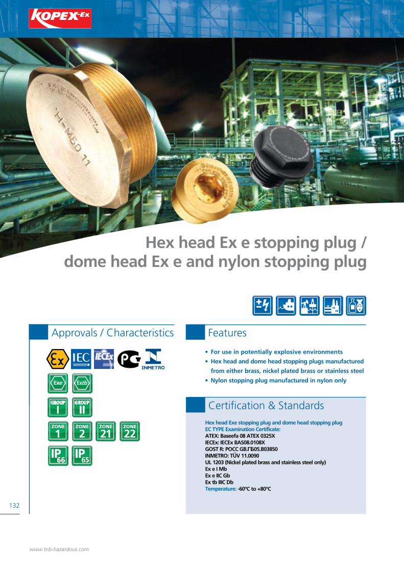
• For use in potentially explosive environments
• Hex head and dome head stopping plugs manufactured
from either brass, nickel plated brass or stainless steel
• Nylon stopping plug manufactured in nylon only
Approvals / Characteristics Features
Hex head Ex e stopping plug / dome head Ex e and nylon stopping plug
Hex head Exe stopping plug and dome head stopping plugEC TYPE Examination Certificate:ATEX: Baseefa 08 ATEX 0325XIECEx: IECEx BAS08.0108XGOST R: POCC GB.ГБ05.B03850INMETRO: TÜV 11.0090UL 1203 (Nickel plated brass and stainless steel only)Ex e I MbEx e IIC Gb Ex tb IIIC DbTemperature: -60ºC to +80ºC
Certification & Standards
132
www.tnb-hazardous.com
b

133
Ex e & Nylon Stopping Plugs
Technical SpecificationsHex head Exe stopping plug
Dome head Exe stopping plug
Stainless Steel Thread SizeType - Metric Metric (mm)
EXS/M16/DSP 16
EXS/M20/DSP 20
EXS/M25/DSP 25
EXS/M32/DSP 32
EXS/M40/DSP 40
EXS/M50/DSP 50
EXS/M63/DSP 63
Brass Thread SizeType - Metric Metric (mm)
EX/M16/DSP 16
EX/M20/DSP 20
EX/M25/DSP 25
EX/M32/DSP 32
EX/M40/DSP 40
EX/M50/DSP 50
EX/M63/DSP 63
Nickel Plated Thread SizeType - Metric Metric (mm)
EXN/M16/DSP 16
EXN/M20/DSP 20
EXN/M25/DSP 25
EXN/M32/DSP 32
EXN/M40/DSP 40
EXN/M50/DSP 50
EXN/M63/DSP 63
N.B. PG stopping plugs available upon request
Stainless Steel Thread SizeType - Metric Metric (mm)
EXS/M16/HSP 16
EXS/M20/HSP 20
EXS/M25/HSP 25
EXS/M32/HSP 32
EXS/M40/HSP 40
EXS/M50/HSP 50
EXS/M63/HSP 63
Brass Thread SizeType - Metric Metric (mm)
EX/M16/HSP 16
EX/M20/HSP 20
EX/M25/HSP 25
EX/M32/HSP 32
EX/M40/HSP 40
EX/M50/HSP 50
EX/M63/HSP 63
Nickel Plated Thread SizeType - Metric Metric (mm)
EXN/M16/HSP 16
EXN/M20/HSP 20
EXN/M25/HSP 25
EXN/M32/HSP 32
EXN/M40/HSP 40
EXN/M50/HSP 50
EXN/M63/HSP 63
N.B. PG stopping plugs available upon request
Nylon stopping plug
Nylon Thread SizeType - Metric Metric (mm)
EX-M16 16
EX-M20 20
EX-M25 25
EX-M32 32
EX-M40 40
EX-M50 50
EX-M63 63
www.tnb-hazardous.comA Member of the ABB Group
Nylon Stopping PlugEC TYPE Examination Certificate: IMQ 13 ATEX 016X, IECEx IMQ 13.0005XExe IIC GbEx tb III DbIP test: IP66-IP68
Certification & Standards
8
Ex e and nylon stopping plugs

Nickel Plated Thread SizeType - Metric Metric (mm)
WHMM03 16
WHMM04 20
WHMM05 25
WHMM06 32
WHMM07 40
WHMM08 50
WHMM09 63
Nickel Plated Thread SizeType - NPT NPT (inch)
– 3/8
WHAM04 1/2
WHAM05 3/4
WHAM06 1
WHAM07 11/4
WHAM08 11/2
WHAM09 2
Nickel Plated Thread SizeType - Metric Metric (mm)
EXN/M16/C 16
EXN/M20/C 20
EXN/M25/C 25
EXN/M32/C 32
EXN/M40/C 40
EXN/M50/C 50
EXN/M63/C 63
EXN/M75/C 75
Nickel Plated Thread SizeType - NPT NPT (inch)
EXN/038/C 3/8
EXN/050/C 1/2
EXN/075/C 3/4
EXN/100/C 1
EXN/125/C 11/4
EXN/150/C 11/2
EXN/200/C 2
EXN/250/C 21/2
Stainless Steel Thread SizeType - Metric Metric (mm)
EXS/M16/C 16
EXS/M20/C 20
EXS/M25/C 25
EXS/M32/C 32
EXS/M40/C 40
EXS/M50/C 50
EXS/M63/C 63
EXS/M75/C 75
Stainless Steel Thread SizeType - NPT NPT (inch)
EXS/038/C 3/8
EXS/050/C 1/2
EXS/075/C 3/4
EXS/100/C 1
EXS/125/C 11/4
EXS/150/C 11/2
EXS/200/C 2
EXS/250/C 21/2
Stainless Steel Thread SizeType - NPT NPT (inch)
– 3/8
MXAH04 1/2
MXAH05 3/4
MXAH06 1
MXAH07 11/4
MXAH08 11/2
– 2
Brass Thread SizeType - Metric Metric (mm)
EX/M16/C 16
EX/M20/C 20
EX/M25/C 25
EX/M32/C 32
EX/M40/C 40
EX/M50/C 50
EX/M63/C 63
EX/M75/C 75
Brass Thread SizeType - NPT NPT (inch)
EX/038/C 3/8
EX/050/C 1/2
EX/075/C 3/4
EX/100/C 1
EX/125/C 11/4
EX/150/C 11/2
EX/200/C 2
EX/250/C 21/2
Brass Thread SizeType - NPT NPT (inch)
– 3/8
WHAB04 1/2
WHAB05 3/4
WHAB06 1
WHAB07 11/4
WHAB08 11/2
– 2
134
Accessories
www.tnb-hazardous.com
Coupler - female to female thread couplers for use in both Exd and Exe applications
Hex locknut
Certification Standard: Baseefa 08 ATEX 0359UIECEx BAS08.0121UTÜV11.0158U
Ex de IIC GbEx tb IIIC Db
Temperature: -60°C to +200°C
Technical Specifications
Stainless Steel Thread SizeType - Metric Metric (mm)
– 16
MXWH04 20
MXWH05 25
MXWH06 32
MXWH07 40
MXWH08 50
– 63
Brass Thread SizeType - Metric Metric (mm)
WHMB03 16
WHMB04 20
WHMB05 25
WHMB06 32
WHMB07 40
WHMB08 50
– 63

Cable Glands, Sealing Washers & Locknuts - Accessories
135
Technical Specifications
Sealing joint washer
OutsideNylon Thread Size Diameter ThicknessType - Metric Metric (mm) (mm) (mm)
EXFM03 16 22.0 1.6
EXFM04 20 26.0 1.6
EXFM05 25 34.3 1.7
EXFM06 32 41.5 1.7
EXFM07 40 52.0 2.0
EXFM08 50 66.5 2.0
EXFM09* 63 84.5 2.0
OutsideFibre Thread Size Diameter ThicknessType - Metric Metric (mm) (mm) (mm)
EXFM03F 16 22.0 1.6
EXFM04F 20 26.0 1.6
EXFM05F 25 34.3 1.7
EXFM06F 32 41.5 1.7
EXFM07F 40 52.0 2.0
EXFM08F 50 66.5 2.0
Earth tag
Brass Diameter (mm)Type - Metric A B C
EX/M20/TAG 20.2 / 20.5 6.5 / 7.0 28.0 / 28.5
EX/M25/TAG 25.2 / 25.7 6.1 / 6.6 30.5 / 31.0
EX/M32/TAG 32.2 / 32.8 12.2 / 12.7 40.0 / 40.5
EX/M40/TAG 40.2 / 40.7 13.0 / 13.5 45.0 / 45.5
EX/M50/TAG 51.0 / 51.5 13.0 / 13.5 58.0 / 58.5
EX/M63/TAG 63.7 / 64.2 13.0 / 13.5 65.0 / 65.5
EX/M75/TAG 76.4 / 76.9 13.0 / 13.5 75.5 / 76.0
Serrated washer
Steel Thread Size Diameter (mm) Type - Metric Metric (mm) Inside Outside
EX/M16/SER 16 17.5 28.0
EX/M20/SER 20 21.9 33.0
EX/M25/SER 25 26.2 40.0
EX/M32/SER 32 33.0 48.1
EX/M40/SER 40 41.5 60.2
EX/M53/SER 50 51.5 70.0
EX/M63/SER 63 64.6 86.8
www.tnb-hazardous.comA Member of the ABB Group
Couplers, sealing washers and locknuts - accessories
C
ØB
ØA

136
Index
www.tnb-hazardous.com
MXAH04 134
MXAH05 134
MXAH06 134
MXAH07 134
BEAVR-12/10 36
BEAVR-17/12 36
BEAVR-23/17 36
BEAVR-29/23 36
BEAVR-36/29 36
BEAVR-48/36 36
BEH-10-0 37
BEH-12-0 37
BEH-17-0 37
BEH-23-0 37
BEH-29-0 37
BEH-36-0 37
BEH-48-0 37
BENR-REM162-24 36
BENR-REM207-28 36
BENR-REM253-32 36
BENR-REM329-44 36
BENR-REM406-50 36
BENR-REM508-65 36
BESGR-1212 35
BESGR-1717 35
BESGR-2323 35
BESGR-2929 35
BESGR-3636 35
BESGR-4848 35
BETR-101010 35
BETR-121212 35
BETR-171717 35
BETR-232323 35
BETR-292929 35
BETR-363636 35
BETR-484848 35
BEYR-121010 35
BEYR-171212 35
BEYR-231717 35
BEYR-292323 35
BEYR-362929 35
BEYR-483636 35
CI-TCAX-100-135-P 89
CI-TCAX-125-151-P 89
CI-TCAX-125-167-P 89
CI-TCAX-125-182-P 89
CI-TCAX-150-192-P 89
CI-TCAX-150-208-P 89
CI-TCAX-200-231-P 89
CI-TCAX-200-250-P 89
CI-TCAX-50-063-P 89
CI-TCAX-50-078-P 89
CI-TCAX-50-089-P 89
CI-TCAX-50-098-P 89
CI-TCAX-75-106-P 89
CI-TCAX-75-118-P 89
CI-TEK-100-137 87
CI-TEK-125-157 87
CI-TEK-125-176 87
CI-TEK-150-198 87
CI-TEK-200-220 87
CI-TEK-200-241 87
CI-TEK-200-262 87
CI-TEK-250-284 87
CI-TEK-300-306 87
CI-TEK-300-328 87
CI-TEK-300-350 87
CI-TEK-400-371 87
CI-TEK-400-392 87
CI-TEK-400-413 87
CI-TEK-400-433 87
CI-TEK-50-066 87
CI-TEK-50-079 87
CI-TEK-50-092 87
CI-TEK-75-105 87
CI-TEK-75-120 87
ECD15 119
ECD284 119
ECD384 119
EVHF-1 123
EVHF-1 125
EVHF-10 125
EVHF-2 123
EVHF-2 125
EVHF-3 123
EVHF-3 125
EVHF-4 123
EVHF-4 125
EVHF-5 123
EVHF-5 125
EVHF-6 123
EVHF-6 125
EVHF-7 123
EVHF-7 125
EVHF-8 123
EVHF-8 125
EVHF-9 125
EX/038/C 134
EX/038/SP 131
EX/038/TSP 131
EX/038-M16/TC 129
EX/050/C 134
EX/050/SP 131
EX/050/TSP 131
EX/050-075/E 129
EX/050-M16/TC 129
EX/050-M20/TC 129
EX/050-M25/TC 129
EX/075/C 134
EX/075/SP 131
EX/075/TSP 131
EX/075-050/R 129
EX/075-100/E 129
EX/075-M16/TC 129
EX/075-M20/TC 129
EX/075-M25/TC 129
EX/075-M32/TC 129
EX/100/C 134
EX/100/SP 131
EX/100/TSP 131
EX/100-050/R 129
EX/100-075/R 129
EX/100-125/E 129
EX/100-M16/TC 129
EX/100-M20/TC 129
EX/100-M25/TC 129
EX/100-M32/TC 129
EX/100-M40/TC 129
EX/125/C 134
EX/125/SP 131
EX/125/TSP 131
EX/125-050/R 129
EX/125-075/R 129
EX/125-100/R 129
EX/125-150/E 129
EX/125-M16/TC 129
EX/125-M20/TC 129
EX/125-M25/TC 129
EX/125-M32/TC 129
EX/125-M40/TC 129
EX/125-M50/TC 129
EX/150/C 134
EX/150/SP 131
EX/150/TSP 131
EX/150-050/R 129
EX/150-075/R 129
EX/150-100/R 129
EX/150-125/R 129
EX/150-200/E 129
EX/150-M16/TC 129
EX/150-M20/TC 129
EX/150-M25/TC 129
EX/150-M32/TC 129
EX/150-M40/TC 129
EX/150-M50/TC 129
EX/150-M63/TC 129
EX/200/C 134
EX/200/SP 131
EX/200/TSP 131
EX/200-050/R 129
EX/200-075/R 129
EX/200-100/R 129
EX/200-125/R 129
EX/200-M16/TC 129
EX/200-M20/TC 129
EX/200-M25/TC 129
EX/200-M32/TC 129
EX/200-M40/TC 129
EX/200-M50/TC 129
EX/200-M63/TC 129
EX/250/C 134
EX/250-050/R 129
EX/250-075/R 129
EX/250-100/R 129
EX/250-125/R 129
EX/250-150/R 129
EX/250-200/R 129
EX/250-300/E 129
EX/250-M16/TC 129
EX/250-M20/TC 129
EX/250-M25/TC 129
EX/250-M32/TC 129
EX/250-M40/TC 129
EX/250-M50/TC 129
EX/300-050/R 129
EX/300-075/R 129
EX/300-100/R 129
EX/300-125/R 129
EX/300-150/R 129
EX/300-200/R 129
EX/300-250/R 129
EX/300-M16/TC 129
EX/300-M20/TC 129
EX/300-M25/TC 129
EX/300-M32/TC 129
EX/300-M40/TC 129
EX/300-M50/TC 129
EX/300-M75/TC 129
EX/M16/C 134
EX/M16/DSP 133
EX/M16/HSP 133
EX/M16/SER 135
EX/M16/SP 131
EX/M16/TSP 131
EX/M16-050/TC 129
EX/M16-M20/E 129
EX/M16-M25/E 129
EX/M20/C 134
EX/M20/DSP 133
EX/M20/HSP 133
EX/M20/SER 135
EX/M20/SP 131
EX/M20/TAG 135
EX/M20/TSP 131
EX/M20-050/TC 129
EX/M20-075/TC 129
EX/M20-M16/R 129
EX/M20-M25/E 129
EX/M20-M32/E 129
EX/M25/C 134
Part No. Page Part No. Page Part No. Page Part No. Page Part No. Page

Index
137
EX/M25/DSP 133
EX/M25/HSP 133
EX/M25/SER 135
EX/M25/SP 131
EX/M25/TAG 135
EX/M25/TSP 131
EX/M25-050/TC 129
EX/M25-075/TC 129
EX/M25-100/TC 129
EX/M25-M16/R 129
EX/M25-M20/R 129
EX/M25-M32/E 129
EX/M25-M40/E 129
EX/M32/C 134
EX/M32/DSP 133
EX/M32/HSP 133
EX/M32/SER 135
EX/M32/SP 131
EX/M32/TAG 135
EX/M32/TSP 131
EX/M32-050/TC 129
EX/M32-075/TC 129
EX/M32-100/TC 129
EX/M32-125/TC 129
EX/M32-M16/R 129
EX/M32-M20/R 129
EX/M32-M25/R 129
EX/M32-M40/E 129
EX/M32-M50/E 129
EX/M40/C 134
EX/M40/DSP 133
EX/M40/HSP 133
EX/M40/SER 135
EX/M40/SP 131
EX/M40/TAG 135
EX/M40/TSP 131
EX/M40-050/TC 131
EX/M40-075/TC 129
EX/M40-100/TC 129
EX/M40-125/TC 129
EX/M40-150/TC 129
EX/M40-M16/R 129
EX/M40-M20/R 129
EX/M40-M25/R 129
EX/M40-M32/R 129
EX/M40-M50/E 129
EX/M40-M63/E 129
EX/M50/C 134
EX/M50/DSP 133
EX/M50/HSP 133
EX/M50/SP 131
EX/M50/TAG 135
EX/M50/TSP 131
EX/M50-050/TC 129
EX/M50-075/TC 129
EX/M50-100/TC 129
EX/M50-125/TC 129
EX/M50-150/TC 129
EX/M50-200/TC 129
EX/M50-M16/R 129
EX/M50-M20/R 129
EX/M50-M25/R 129
EX/M50-M32/R 129
EX/M50-M40/R 129
EX/M50-M63/E 129
EX/M50-M75/E 129
EX/M53/SER 135
EX/M63/C 134
EX/M63/DSP 133
EX/M63/HSP 133
EX/M63/SER 135
EX/M63/SP 131
EX/M63/TAG 135
EX/M63/TSP 131
EX/M63-050/TC 129
EX/M63-075/TC 129
EX/M63-100/TC 129
EX/M63-125/TC 129
EX/M63-150/TC 129
EX/M63-200/TC 129
EX/M63-M16/R 129
EX/M63-M20/R 129
EX/M63-M25/R 129
EX/M63-M32/R 129
EX/M63-M40/R 129
EX/M63-M50/R 129
EX/M63-M75/E 129
EX/M75/C 134
EX/M75/TAG 135
EX/M75-050/TC 129
EX/M75-075/TC 129
EX/M75-100/TC 129
EX/M75-125/TC 129
EX/M75-150/TC 129
EX/M75-200/TC 129
EX/M75-M16/R 129
EX/M75-M20/R 129
EX/M75-M25/R 129
EX/M75-M32/R 129
EX/M75-M40/R 129
EX/M75-M50/R 129
EX/M75-M63/R 129
EX03AMC1 55
EX03AMC2 57
EX03AMC3 59
EX03ASC1 55
EX03ASC3 59
EX03MMC1 55
EX03MMC2 57
EX03MMC3 59
EX03MSC1 55
EX03MSC3 59
EX04AC4 61
EX04AC5 61
EX04ALC1 55
EX04ALC2 57
EX04AMC1 55
EX04AMC2 57
EX04AMC3 59
EX04ASC1 55
EX04ASC3 59
EX04MC4 61
EX04MC5 63
EX04MLC1 55
EX04MLC2 57
EX04MMC1 55
EX04MMC2 57
EX04MMC3 59
EX04MSC1 55
EX04MSC3 59
EX05AC4 61
EX05AC5 63
EX05ALC1 55
EX05ALC2 57
EX05ALC3 59
EX05AMC1 55
EX05AMC2 57
EX05AMC3 59
EX05ASC1 55
EX05ASC3 59
EX05MC4 61
EX05MC5 63
EX05MLC1 55
EX05MLC2 57
EX05MLC3 59
EX05MMC1 55
EX05MMC2 57
EX05MMC3 59
EX05MSC1 55
EX05MSC3 59
EX06AC4 61
EX06AC5 63
EX06ALC2 57
EX06AMC1 55
EX06AMC2 57
EX06AMC3 59
EX06ASC1 55
EX06ASC3 59
EX06MC4 61
EX06MC5 63
EX06MLC2 57
EX06MMC1 55
EX06MMC2 57
EX06MMC3 57
EX06MSC1 55
EX06MSC3 59
EX07AC4 61
EX07AC5 63
EX07ALC2 57
EX07AMC1 55
EX07AMC2 57
EX07AMC3 59
EX07ASC1 55
EX07ASC3 59
EX07MC4 61
EX07MC5 63
EX07MLC2 57
EX07MMC1 55
EX07MMC2 57
EX07MMC3 59
EX07MSC1 55
EX07MSC3 59
EX08AC4 61
EX08AC5 63
EX08ALC2 57
EX08AMC1 55
EX08AMC2 57
EX08AMC3 59
EX08ASC1 55
EX08ASC3 59
EX08MC4 61
EX08MC5 63
EX08MLC2 57
EX08MMC1 55
EX08MMC2 57
EX08MMC3 59
EX08MSC1 55
EX08MSC3 59
EX09AC4 61
EX09AC5 63
EX09ALC2 57
EX09AMC1 55
EX09AMC2 57
EX09AMC3 59
EX09ASC1 55
EX09ASC3 59
EX09MC4 61
EX09MC5 63
EX09MLC2 57
EX09MMC1 55
EX09MMC2 57
EX09MMC3 59
EX09MSC1 55
EX09MSC3 59
EX10ALC2 57
EX10AMC1 55
EX10AMC2 57
EX10AMC3 59
EX10ASC1 55
EX10ASC3 59
Part No. Page Part No. Page Part No. Page Part No. Page Part No. Page
www.tnb-hazardous.comA Member of the ABB Group
Index

138
Index
www.tnb-hazardous.com
EX10MLC2 57
EX10MMC1 55
EX10MMC2 57
EX10MMC3 59
EX10MSC1 55
EX10MSC3 59
EX11AMC1 55
EX11ALC2 57
EX11AMC2 57
EX11AMC3 59
EX11ASC1 55
EX11ASC3 59
EX11MLC2 57
EX11MMC1 55
EX11MMC2 57
EX11MMC3 59
EX11MSC1 55
EX11MSC3 59
EX12ALC2 57
EX12AMC2 57
EX12MLC2 59
EX12MMC2 57
EX13AMC2 59
EX13MMC2 59
EX14AMC2 59
EX14MMC2 59
EXB010 28
EXB03 28
EXB04 28
EXB05 28
EXB06 28
EXB07 28
EXB08 28
EXB09 28
EXBB03 28
EXBB04 28
EXBB05 28
EXBB06 28
EXBB07 28
EXBB08 28
EXBBT03 38
EXBBT04 38
EXBBT05 38
EXBBT06 38
EXBBT07 38
EXBBT08 38
EXBBT09 38
EXBQA0304 31
EXBQA0404 31
EXBQA0505 31
EXBQA0606 31
EXBQA0707 31
EXBQA0808 31
EXBQM0303 31
EXBQM0404 31
EXBQM0505 31
EXBQM0606 31
EXBQM0707 31
EXBQM0808 31
EXCG050M 65
EXCG050S 65
EXCG075S 65
EXCG100S 65
EXCGM20M 65
EXCGM20ML 65
EXCGM20S 65
EXCGM20SL 65
EXCGM25M 65
EXCGM25S 65
EXCGM25SL 65
EXCGM32M 65
EXCGM32S 65
EXCGM40M 65
EXCGM40S 65
EXCGM50S 65
EXCGM63S 65
EXFM03 135
EXFM03F 135
EXFM04 135
EXFM04F 135
EXFM05 135
EXFM05F 135
EXFM06 135
EXFM06F 135
EXFM07 135
EXFM07F 135
EXFM08 135
EXFM08F 135
EXFM09 135
EXFU-1 117
EXFU-10 117
EXFU-2 117
EXFU-3 117
EXFU-4 117
EXFU-5 117
EXFU-6 117
EXFU-8 117
EXFU-9 117
EXLB03 38
EXLB04 38
EXLB05 38
EXLB06 38
EXLB07 38
EXLB08 38
EXLB09 38
EXLB-1 107
EXLB-2 107
EXLB-3 107
EXLH03 39
EXLH04 39
EXLH05 39
EXLH06 39
EXLH07 39
EXLH08 39
EXLH09 39
EXLHC03 39
EXLHC04 39
EXLHC05 39
EXLHC06 39
EXLHC07 39
EXLHC08 39
EXLHC09 39
EXLLH03 39
EXLLH04 39
EXLLH05 39
EXLLH06 39
EXLLH07 39
EXLLH08 39
EXLLH09 39
EXLT03 38
EXLT04 38
EXLT05 38
EXLT06 38
EXLT07 38
EXLT08 38
EXLT09 38
EX-M16 133
EX-M20 133
EX-M25 133
EX-M32 133
EX-M40 133
EX-M50 133
EX-M63 133
EXMU-1 117
EXMU-2 117
EXMU-3 117
EXN/038/C 134
EXN/038/SP 131
EXN/038/TSP 131
EXN/050/C 134
EXN/050/SP 131
EXN/050/TSP 131
EXN/075/C 134
EXN/075/SP 131
EXN/075/TSP 131
EXN/100/C 134
EXN/100/SP 131
EXN/100/TSP 131
EXN/125/C 134
EXN/125/SP 131
EXN/125/TSP 131
EXN/150/C 134
EXN/150/SP 131
EXN/150/TSP 131
EXN/200/C 134
EXN/200/SP 131
EXN/200/TSP 131
EXN/250/C 134
EXN/M16/C 134
EXN/M16/DSP 133
EXN/M16/HSP 133
EXN/M16/SP 131
EXN/M16/TSP 131
EXN/M20/C 134
EXN/M20/DSP 133
EXN/M20/HSP 133
EXN/M20/SP 131
EXN/M20/TSP 131
EXN/M25/C 134
EXN/M25/DSP 133
EXN/M25/HSP 133
EXN/M25/SP 131
EXN/M25/TSP 131
EXN/M32/C 134
EXN/M32/DSP 133
EXN/M32/HSP 133
EXN/M32/SP 131
EXN/M32/TSP 131
EXN/M40/C 134
EXN/M40/DSP 133
EXN/M40/HSP 133
EXN/M40/SP 131
EXN/M40/TSP 131
EXN/M50/C 134
EXN/M50/DSP 133
EXN/M50/HSP 133
EXN/M50/SP 131
EXN/M50/TSP 131
EXN/M63/C 134
EXN/M63/DSP 133
EXN/M63/HSP 133
EXN/M63/SP 133
EXN/M63/TSP 133
EXN/M75/C 134
EXPF-16 125
EXPQA0304 31
EXPQA0404 31
EXPQA0505 31
EXPQA0606 31
EXPQA0707 31
EXPQA0808 31
EXPQA0909 31
EXPQA1010 31
EXPQM0303 31
EXPQM0404 31
EXPQM0505 31
EXPQM0606 31
EXPQM0707 31
EXPQM0808 31
EXPQM0909 31
Part No. Page Part No. Page Part No. Page Part No. Page Part No. Page

Index
139
EXPQM1010 31
EXS/038/C 134
EXS/038/SP 131
EXS/038/TSP 131
EXS/050/C 134
EXS/050/SP 131
EXS/050/TSP 131
EXS/075/C 134
EXS/075/SP 131
EXS/075/TSP 131
EXS/100/C 134
EXS/100/SP 131
EXS/100/TSP 131
EXS/125/C 134
EXS/125/SP 131
EXS/125/TSP 131
EXS/150/C 134
EXS/150/SP 131
EXS/150/TSP 131
EXS/200/C 134
EXS/200/SP 131
EXS/200/TSP 131
EXS/250/C 134
EXS/M16/C 134
EXS/M16/DSP 133
EXS/M16/HSP 133
EXS/M16/SP 131
EXS/M16/TSP 131
EXS/M20/C 134
EXS/M20/DSP 133
EXS/M20/HSP 133
EXS/M20/SP 131
EXS/M20/TSP 131
EXS/M25/C 134
EXS/M25/DSP 133
EXS/M25/HSP 133
EXS/M25/SP 131
EXS/M25/TSP 131
EXS/M32/C 134
EXS/M32/DSP 133
EXS/M32/HSP 133
EXS/M32/SP 131
EXS/M32/TSP 131
EXS/M40/C 134
EXS/M40/DSP 133
EXS/M40/HSP 133
EXS/M40/SP 131
EXS/M40/TSP 131
EXS/M50/C 134
EXS/M50/DSP 133
EXS/M50/HSP 133
EXS/M50/SP 131
EXS/M50/TSP 131
EXS/M63/C 134
EXS/M63/DSP 133
EXS/M63/HSP 133
EXS/M63/SP 131
EXS/M63/TSP 131
EXS/M75/C 134
EXSB03 40
EXSB04 40
EXSB05 40
EXSB06 40
EXSB07 40
EXSB08 40
EXSB09 40
EXSBBT03 40
EXSBBT04 40
EXSBBT05 40
EXSBBT06 40
EXSBBT07 40
EXSBBT08 40
EXSBBT09 40
EXSC-16 125
EXSC-2 125
EXSC-8 125
EXSH03 41
EXSH04 41
EXSH05 41
EXSH06 41
EXSH07 41
EXSH08 41
EXSH09 41
EXSHC03 41
EXSHC04 41
EXSHC05 41
EXSHC06 41
EXSHC07 41
EXSHC08 41
EXSHC09 41
EXSLH03 41
EXSLH04 41
EXSLH05 41
EXSLH06 41
EXSLH07 41
EXSLH08 41
EXSLH09 41
EXST03 40
EXST04 40
EXST05 40
EXST06 40
EXST07 40
EXST08 40
EXST09 40
EXT-1 107
EXT-2 107
EXT-3 107
EXUN-1 99
EXUN-11 99
EXUN-2 99
EXUN-22 99
EXUN-3 99
EYD101-TB 119
EYD11-TB 119
EYD21-TB 119
EYD31-TB 119
EYD41-TB 119
EYD51-TB 119
EYD61-TB 119
EYD71-TB 119
EYD81-TB 119
EYD91-TB 119
EYS101-TB 121
EYS11-TB 121
EYS1-TB 121
EYS21-TB 121
EYS2-TB 121
EYS31-TB 121
EYS3-TB 121
EYS41-TB 121
EYS4-TB 121
EYS51-TB 121
EYS5-TB 121
EYS61-TB 121
EYS71-TB 121
EYS81-TB 121
EYS91-TB 121
EYVF-1 123
EYVF-11 123
EYVF-11 125
EYVF-2 123
EYVF-22 123
EYVF-22 125
EYVF-3 123
EYVF-33 123
EYVF-33 125
GAC-1 99
GAC-2 99
GAC-3 99
GAD-123 100
GAE-2 99
GAFX-1 101
GAFX-2 101
GAJ-123 101
GAJ-4 101
GAJ-56 101
GAJU-2 101
GAJU-3 101
GAJU-6 101
GAL-1 99
GAL-2 99
GAL-3 99
GAL-4 99
GAL-5 99
GAL-6 99
GALB-1 100
GALB-2 100
GALB-3 100
GALB-4 100
GALB-6 100
GAS-123 100
GAS-4 100
GAS-56 100
GASS-1 104
GASS-2 104
GASS-3 104
GAT-1 100
GAT-2 100
GAT-3 100
GAT-4 100
GAT-6 100
GAX-1 100
GAX-2 100
GAX-3 100
GAX-5 100
GRL-LUG1/4-20 85
GRL-LUG1032 85
GUA14-TB 95
GUA16-TB 95
GUA24-TB 95
GUA26-TB 95
GUA36-TB 95
GUA47-TB 95
GUA59-TB 95
GUAB14-TB 95
GUAB16-TB 95
GUAB24-TB 95
GUAB26-TB 95
GUAB36-TB 95
GUAB47-TB 95
GUAB59-TB 95
GUAB69-TB 95
GUAB79-TB 95
GUAC14-TB 95
GUAC16-TB 95
GUAC24-TB 95
GUAC26-TB 95
GUAC36-TB 95
GUAC47-TB 95
GUAC49-TB 95
GUAC59-TB 95
GUAC69-TB 95
GUAD14-TB 95
GUAD16-TB 95
GUAD24-TB 95
GUAD26-TB 95
GUAD36-TB 95
GUAD49-TB 95
GUAL14-TB 96
GUAL16-TB 96
Part No. Page Part No. Page Part No. Page Part No. Page Part No. Page
www.tnb-hazardous.comA Member of the ABB Group
Index

140
Index
www.tnb-hazardous.com
GUAL24-TB 96
GUAL26-TB 96
GUAL36-TB 96
GUAL47-TB 96
GUAL49-TB 96
GUAL59-TB 96
GUAL69-TB 96
GUAM14-TB 96
GUAM16-TB 96
GUAM24-TB 96
GUAM26-TB 96
GUAN14-TB 97
GUAN16-TB 97
GUAN24-TB 97
GUAN26-TB 97
GUAN36-TB 97
GUAN47-TB 97
GUAN59-TB 97
GUAN69-TB 97
GUAT14-TB 97
GUAT16-TB 97
GUAT24-TB 97
GUAT26-TB 97
GUAT36-TB 97
GUAT37-TB 97
GUAT47-TB 97
GUAT49-TB 97
GUAT59-TB 97
GUAT69-TB 97
GUAT79-TB 97
GUAW14-TB 97
GUAW16-TB 97
GUAW24-TB 97
GUAW26-TB 97
GUAX14-TB 97
GUAX16-TB 97
GUAX24-TB 97
GUAX26-TB 97
GUAX36-TB 97
GUAX37-TB 97
GUAX47-TB 97
GUAX49-TB 97
GUAX59-TB 97
GUAX69-TB 97
GUP214-TB 105
GUP215-TB 105
GYF-1 111
GYF-2 111
GYF-3 111
GYF-4 111
GYF-5 111
HAA*0304 43
HAA*0304E 44
HAA*0404 43
HAA*0404E 44
HAA*0505 43
HAA*0505E 44
HAA*0606 43
HAA*0606E 44
HAA*0707 43
HAA*0707E 44
HAA*0808 43
HAA*0808E 44
HAA0304U 46
HAA0304U/SW 47
HAA0404U 46
HAA0404U/SW 47
HAA0505U 46
HAA0505U/SW 47
HAA0606U 46
HAA0606U/SW 47
HAA0707U 46
HAA0707U/SW 47
HAA0808U 46
HAA0808U/SW 47
HAA0909U 46
HAA0909U/SW 47
HAAM0304U 46
HAAM0304U/SW 47
HAAM0404U 46
HAAM0404U/SW 47
HAAM0505U 46
HAAM0505U/SW 47
HAAM0606U 46
HAAM0606U/SW 47
HAAM0707U 46
HAAM0707U/SW 47
HAAM0808U 46
HAAM0808U/SW 47
HAAM0909U 46
HAAM0909U/SW 47
HAAS0304U 46
HAAS0404U 46
HAAS0505U 46
HAAS0606U 46
HAAS0707U 46
HAAS0808U 46
HAAS0909U 46
HAM*0304 43
HAM*0304E 44
HAM*0404 43
HAM*0404E 44
HAM*0505 43
HAM*0505E 44
HAM*0606 43
HAM*0606E 44
HAM*0707 43
HAM*0707E 44
HAM*0808 43
HAM*0808E 44
HAM0304U 46
HAM0304U/SW 47
HAM0404U 46
HAM0404U/SW 47
HAM0505U 46
HAM0505U/SW 47
HAM0606U 46
HAM0606U/SW 47
HAM0707U 46
HAM0707U/SW 47
HAM0808U 46
HAM0808U/SW 47
HAM0909U 46
HAM0909U/SW 47
HAMM0304U 46
HAMM0304U/SW 47
HAMM0404U 46
HAMM0404U/SW 47
HAMM0505U 46
HAMM0505U/SW 47
HAMM0606U 46
HAMM0606U/SW 47
HAMM0707U 46
HAMM0707U/SW 47
HAMM0808U 46
HAMM0808U/SW 47
HAMM0909U 46
HAMM0909U/SW 47
HAMS0304U 46
HAMS0404U 46
HAMS0505U 46
HAMS0606U 46
HAMS0707U 46
HAMS0808U 46
HAMS0909U 46
HEAK-M32/25-13 37
HEAK-M40/32-13 37
HEAK-M50/40-14 37
HEAK-M63/63-14 37
L050GRL 85
L075GRL 85
L100GRL 85
L125GRL 85
L150GRL 85
L250GRL 85
L300GRL 85
L350GRL 85
L400GRL 85
L500GRL 85
LBY15-TB 111
LBY25-TB 111
LBY35-TB 111
LBY45-TB 111
LBY55-TB 111
LBY65-TB 111
MXWH04 134
MXWH05 134
MXWH06 134
MXWH07 134
MXWH08 134
NEAV-M120-10 34
NEAV-M162-10 34
NEAV-M207-10 34
NEAV-M253-11 34
NEAV-M257-11 34
NEAV-M323-13 34
NEAV-M329-13 34
NEAV-M406-13 34
NEAV-M409-13 34
NEAV-M506-14 34
NEAV-M508-14 34
NEAV-M638-14 34
NEBV-M207-10 34
NEBV-M253-11 34
NEBV-M257-11 34
NEBV-M323-13 34
NEBV-M329-13 34
NEBV-M406-13 34
NEBV-M409-13 34
NEBV-M506-14 34
NEBV-M508-14 34
NEBV-M638-14 34
NEIR-M120 36
NEIR-M160 36
NEIR-M162 36
NEIR-M207 36
NEIR-M253 36
NEIR-M329 36
NEIR-M406 36
NEIR-M508 36
NEIR-M638 36
NENV-M120-10 33
NENV-M160-10 33
NENV-M162-10 33
NENV-M202-10 33
NENV-M207-10 33
NENV-M253-11 33
NENV-M257-11 33
NENV-M323-13 33
NENV-M329-13 33
NENV-M406-13 33
NENV-M409-13 33
NENV-M506-14 33
NENV-M508-14 33
NENV-M638-14 33
NENZ-M120S/P 33
NENZ-M160S/P 33
NENZ-M202S/P 33
NENZ-M207S/P 33
NENZ-M257S/P 33
Part No. Page Part No. Page Part No. Page Part No. Page Part No. Page

Index
141
NENZ-M323S/P 33
NENZ-M409S/P 33
NENZ-M506S/P 33
NENZ-M508S/P 33
NENZ-M638S/P 33
NEWV-M120-10 34
NEWV-M160-10 34
NEWV-M162-10 34
NEWV-M202-10 34
OEC1-TB 109
OEC2-TB 109
OELB1-TB 109
OELB2-TB 109
OELL1-TB 109
OELL2-TB 109
OELR1-TB 109
OELR2-TB 109
OET1-TB 109
OET2-TB 109
PLG10-TB 113
PLG1-TB 113
PLG2-TB 113
PLG3-TB 113
PLG4-TB 113
PLG5-TB 113
PLG6-TB 113
PLG7-TB 113
PLG8-TB 113
PLG9-TB 113
RE106-TB 113
RE107-TB 113
RE108-TB 113
RE21-TB 113
RE31-TB 113
RE32-TB 113
RE41-TB 113
RE42-TB 113
RE43-TB 113
RE51-TB 113
RE52-TB 113
RE53-TB 113
RE54-TB 113
RE61-TB 113
RE62-TB 113
RE63-TB 113
RE64-TB 113
RE65-TB 113
RE73-TB 113
RE74-TB 113
RE75-TB 113
RE76-TB 113
RE83-TB 113
RE84-TB 113
RE85-TB 113
RE86-TB 113
RE87-TB 113
RE96-TB 113
RE97-TB 113
RE98-TB 113
REC21-TB 113
REC31-TB 113
REC32-TB 113
SC4-KIT-1 77
SC4-KIT-1 81
SC65 77
SC65 81
ST038-461S 75
ST050-462 75
ST050-464 75
ST050-465 75
ST050-466 75
ST075-467 75
ST075-468 75
ST100-469 75
ST125-470 75
ST125-471 75
ST125-550 75
ST150-472 75
ST150-473 75
ST200-474 75
ST200-475 75
ST200-476 75
ST200-551 75
ST250-477 75
ST250-478 75
ST300-479 75
ST300-480 75
ST300-481 75
ST350-482 75
ST350-483 75
ST400-484 75
ST400-485 75
ST400-486 75
STE050 79
STE050-DATA 79
STE050-DATAGRL 85
STE050GRL 85
STE075 79
STE075GRL 85
STE100 79
STE100GRL 85
STE125 79
STE125GRL 85
STE150 79
STE150GRL 85
STE200 79
STE200GRL 85
STE250 79
STE250GRL 85
STE300 79
STE300GRL 85
STE350 79
STE350GRL 85
STE400 79
STE400GRL 85
STED050 83
STED075 83
STEX075 81
STEX100 81
STEX125 81
STEX150 81
STEX200 81
STEX250 81
STEX300 81
STEX350 81
STEX400 81
STX050-462 77
STX050-462 81
STX050-464 77
STX050-464 81
STX075-465 77
STX075-466 77
STX100-467 77
STX100-468 77
STX125-469 77
STX150-470 77
STX150-471 77
STX150-550 77
STX200-472 77
STX200-473 77
STX200-474 77
STX250-475 77
STX250-476 77
STX300-478 77
STX300-478 77
STX350-480 77
STX350-481 77
STX400-482 77
STX400-483 77
STX400-484 77
STX400-485 77
UNF1005-TB 115
UNF105-TB 115
UNF205-TB 115
UNF305-TB 115
UNF405-TB 115
UNF505-TB 115
UNF605-TB 115
UNF705-TB 115
UNF805-TB 115
UNF905-TB 115
UNY1005-TB 115
UNY105-TB 115
UNY205-TB 115
UNY305-TB 115
UNY405-TB 115
UNY505-TB 115
UNY605-TB 115
UNY705-TB 115
UNY805-TB 115
UNY905-TB 115
WHAB04 134
WHAB05 134
WHAB06 134
WHAB07 134
WHAB08 134
WHAM04 134
WHAM05 134
WHAM06 134
WHAM07 134
WHAM08 134
MXAH08 134
WHAM09 134
WHMB03 134
WHMB04 134
WHMB05 134
WHMB06 134
WHMB07 134
WHMB08 134
WHMM03 134
WHMM04 134
WHMM05 134
WHMM06 134
WHMM07 134
WHMM08 134
WHMM09 134
X/200-150/R 129
XESX0250 29
XESX0350 29
XESX0450 29
XESX0550 29
XESX0650 29
XESX0730 29
XESX0830 29
XESXG-17BY.50 29
XESXG-23BY.50 29
XESXG-29BY.50 29
XESXG-36BY.30 29
XESXG-48BY.30 29
XESXT-10BY.50 29
XESXT-12BY.50 29
XPLFL110 49
XPLFL112 49
XPLFL115 49
XPLFL118 49
XPLFL124 49
XPLFL16 49
XPLFL18 49
XPLFL212 49
XPLFL215 49
XPLFL218 49
XPLFL224 49
XPLFL236 49
XPLFL318 49
Part No. Page Part No. Page Part No. Page Part No. Page Part No. Page
www.tnb-hazardous.comA Member of the ABB Group
Index

USA and Canada
142
Thomas & Betts worldwideindustrial capabilities
Thomas & Betts CorporationWorld Headquarters
8155 T&B BoulevardMemphis, TN 38125T 901.252.8000I www.tnb-europe.com
Kopex-ExUK Sales Office
Station Road, Coleshill, Birmingham, B46 1HTT +44 (0) 1675 468 213F +44 (0) 1675 468 280I www.kopex-ex.com
Thomas & BettsEMEA European Centre
200 Chaussee de Waterloo B-1640 Rhode-St-GeneseBelgiumT +32 (0) 2 359 82 00F +44 (0) 2 359 82 01E [email protected]
Thomas & BettsCanada
700 Thomas Avenue Saint-Jean-sur-Richelieu, QuebecJ2X 2M9T 450.347.5318F 450.347.1976E www.tnb.ca
Thomas & BettsAsia (Singapore) Pte Ltd
10 Ang Mo kio Street 65, #06-07 TechpointSingapore 569059T +65 6720 8828F +65 6720 8780E [email protected]
DTSInternational Call Centre
Z.I. Parc d’Activités de la Gare19 à 21 avenue Henri BeaudeletB.P. 27 - 77831 Ozoir Cedex FranceT +33 (0) 1 64 40 27 26F +33 (0) 1 64 40 20 11I www.tnb-hazardous.com
T&B Headquarters
www.tnb-hazardous.com

www.tnb-hazardous.comA Member of the ABB Group
Thomas & Betts - Industrial Capabilities

Flexible C
on
du
it Systems, G
land
s, Rig
id C
on
du
it Fitting
s & A
ccessories fo
r Hazard
ou
s and
Ho
stile Areas
Product CatalogueFlexible Conduit Systems, Glands,
Rigid Conduit Fittings and Accessories for Hazardous and Hostile AreasThe contents of this Thomas & Betts catalogue have been carefully checked for accuracy at the time of print. However,
Thomas & Betts does not provide a catalogue warranty of any kind, express or implied, in this respect and shall not be liable for any loss or damage that may result from any use or as a consequence of any inaccuracies in or any omissions from the information contained within this catalogue.
Copyright Thomas & Betts 2014. Copyright in these pages is owned by Thomas & Betts except where otherwise indicated. No part of this publication may be reproduced, copied or transmitted in any form or by any means, without our prior written permission. Images, trade marks, brands, designs and technology are also protected by other intellectual property rights and may not be reproduced or appropriated in any manner without written permission of their respective owners. Thomas & Betts reserves the right to change and improve any product specifications or other mentions in the catalogue at its own discretion and at any time. These conditions of use are governed by the laws of the Netherlands and the courts of Amsterdam shall have exclusive jurisdiction in any dispute.
Thomas & Betts manufactures and designs a wide range of electrical equipment for hazardous and hostile environments to ensure the safety of the personnel working in them. The extensive range covers Kopex-Ex metallic and non metallic conduit and fittings, Star Teck(r) teck cable fittings and T&B(r) rigid conduit fittings. These products are approved to a wide range of hazardous area standards including ATEX, IECEx, UL, CSA, GOST and Inmetro.
Thomas & Betts Sales Offices
CanadaT +1 450 347 5318 E [email protected]
France / BelgiumT +33 (0) 1 64 40 27 26
Germany / AustriaT +49 (0) 62 21 701-1800 E [email protected]
ItalyT +39 (0) 2 2415 3000
NetherlandsT +31 (0) 180 641 888E [email protected]
SpainT +34 938 45 4570E [email protected]
Switzerland (PMA)T +41 44 905 61 11 E [email protected]
UKT +44 (0) 1675 468 213E [email protected]
LIT-
152G
BR 0
9/14
• D
esig
ned
by w
ww
.uc4
.co.
uk
A Member of the ABB Group A Member of the ABB Group


