+ All Categories
Home > Documents > Thread Data

Thread Data

Date post: 13-Nov-2014
Category:
Upload: balusandeep20
View: 2,018 times
Download: 3 times
Share this document with a friend
26
Nomenclature Left/Right Thread Types Threads are normally Right Handed and unless otherwise stated this is the norm. This means that the nut screws on with a CLOCKWISE rotation. Left Hand threads are of course the opposite. Left Handed Threads are used extensively in the Motor Industry to secure rotating parts such as Drive Shafts, Gears etc. where the normal angular rotation would tend to tighten the nut. Left & Right Hand threads are used, as appropriate, on the Offside/Nearside of the Vehicle. When working on rotating parts always check the hand of the thread or consult the correct instruction manual. It is not uncommon for Wheel Nuts to be Left or Right handed. Use caution. Thread Pitch Usually expressed in threads per inch (tpi) or as an absolute dimension for one single pitch. ie 1mm. 0.2mm .75mm etc. Multi-start threads are basically the single start form, but with the pitch doubled etc. Very rare to come across these in model engineering. Thread Included Angle. Apart from a number of specialist threads the included angles for the most common threads are as follows. BA 47½°. BSW, BSF 55°. UNF, UNC, ANF, ANC 60°. Metric or ISO 60°. British Standard Cycle Thread (BSC) 60°. Acme 29°. Do not be tempted to use male & female threads with differing V angles. All the load is transferred to the thread crests and causes high stress levels, leading to slackening in service and premature failure. Root & Crest Form A major part of any thread is the crest & root form. Usually but not always this takes the form of a radius. Sometimes a flat. The root & crest form may also vary on the male & female threads. Production of a correct form, is for the average modeller virtually impossible. The ISO Metric threads are however an exception. The standard allows for flat roots & crests (p/8 & p/4) It is possible to produce a "V" tool with a rounded root & let the crest remain as a flat. Where taps & dies are used the correct form is produced automatically.. When screw cutting it is now possible to buy ceramic tips that will automatically produce the correct root and crest radii. Since an insert is required for each form & pitch this puts their use outside the reach of most modellers due to cost. A 100% sharp "V" is undesirable as it may form the stress point for fracture and on bolts, cut fingers. Adding a small radius on the "V" tool with a stone is probably the best we can achieve. Another very good way is to use part of a new tap as a thread chaser & skim off the last few tenths & form the radii. Application of the correct root & crest radii does of course reduce the Actual thread depth compared to the full Theoretical Triangular "V" depth.
Transcript

Nomenclature

Left/Right Thread Types

Threads are normally Right Handed and unless otherwise stated this is the norm. This means that the nut screws on with a

CLOCKWISE rotation. Left Hand threads are of course the opposite. Left Handed Threads are used extensively in the Motor Industry

to secure rotating parts such as Drive Shafts, Gears etc. where the normal angular rotation would tend to tighten the nut. Left & Right

Hand threads are used, as appropriate, on the Offside/Nearside of the Vehicle. When working on rotating parts always check the hand

of the thread or consult the correct instruction manual. It is not uncommon for Wheel Nuts to be Left or Right handed. Use caution.

Thread Pitch

Usually expressed in threads per inch (tpi) or as an absolute dimension for one single pitch. ie 1mm. 0.2mm .75mm etc. Multi-start

threads are basically the single start form, but with the pitch doubled etc. Very rare to come across these in model engineering.

Thread Included Angle.

Apart from a number of specialist threads the included angles for the most common threads are as follows. BA 47½°. BSW, BSF 55°.

UNF, UNC, ANF, ANC 60°. Metric or ISO 60°. British Standard Cycle Thread (BSC) 60°. Acme 29°. Do not be tempted to use male

& female threads with differing V angles. All the load is transferred to the thread crests and causes high stress levels, leading to

slackening in service and premature failure.

Root & Crest Form

A major part of any thread is the crest & root form. Usually but not always this takes the form of a radius. Sometimes a flat. The root

& crest form may also vary on the male & female threads. Production of a correct form, is for the average modeller virtually

impossible. The ISO Metric threads are however an exception. The standard allows for flat roots & crests (p/8 & p/4) It is possible to

produce a "V" tool with a rounded root & let the crest remain as a flat. Where taps & dies are used the correct form is produced

automatically.. When screw cutting it is now possible to buy ceramic tips that will automatically produce the correct root and crest

radii. Since an insert is required for each form & pitch this puts their use outside the reach of most modellers due to cost. A 100%

sharp "V" is undesirable as it may form the stress point for fracture and on bolts, cut fingers. Adding a small radius on the "V" tool

with a stone is probably the best we can achieve. Another very good way is to use part of a new tap as a thread chaser & skim off the

last few tenths & form the radii. Application of the correct root & crest radii does of course reduce the Actual thread depth compared

to the full Theoretical Triangular "V" depth.

Effective or Pitch diameter.

On a parallel thread it is the diameter of an imaginary cylinder which would pass through the threads at such a point that both male

and female thread were the same width. This point is usually but not always 1/2 the thread depth. It is only at 1/2 depth when the root

& crest radii are the same.

Thread Identification.

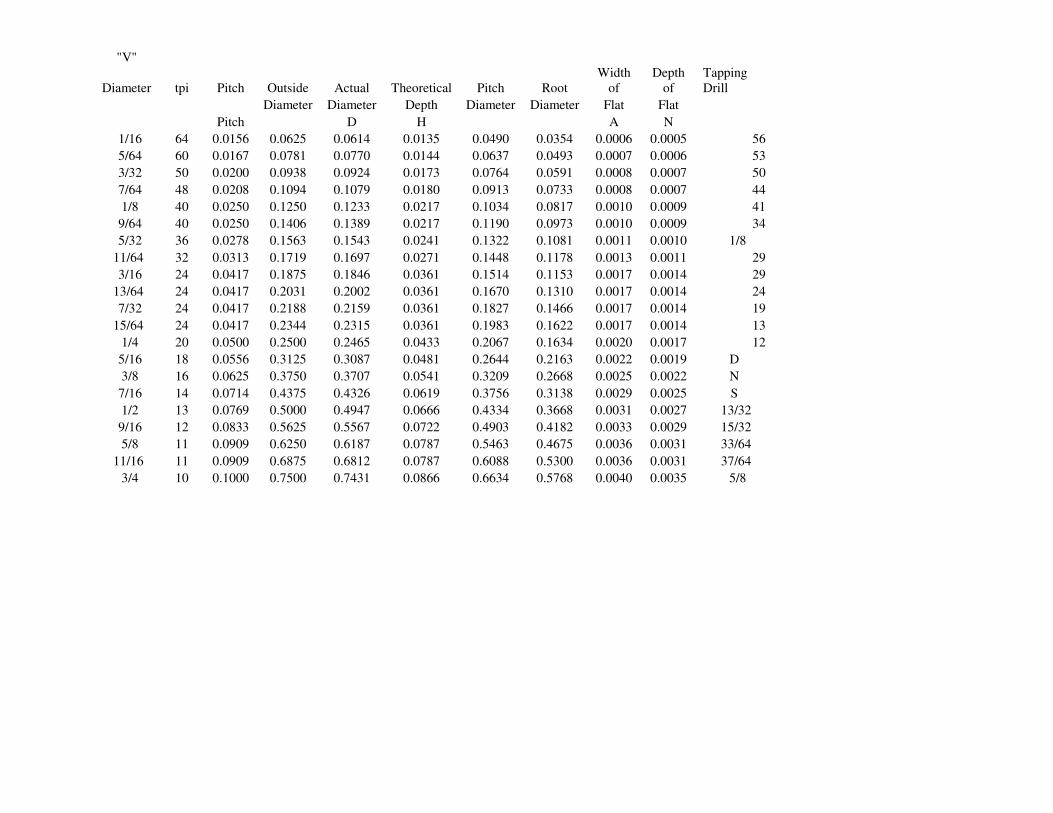
With one or two exceptions (Lead screws, Vice Threads etc.) all the threads we meet are of the "V" form. Only the included angle

varies and this is difficult to determine in the smaller sizes without special equipment. (Optical projectors etc.)

1) The first step is to determine the diameter and see if the thread is (or may be) Imperial or Metric. For example 5/16" & 8mm are

very close together (only 2.5 thou !)

2) Next step is the pitch or threads per inch (tpi) If we ignore the fact that it may or may not be a metric thread, determine the number

of threads in an inch. Lets say it comes to 25.5 approx. This equates to a 1mm pitch & if the dia was 6mm this is almost certain to be

an ISO Metric Coarse M6 thread (ISO is the International Standards Organization) Thread pitch gauges, Taps, existing threads of

known size etc. may be used. Try rolling the thread form onto a piece of paper and measure the pitch with an eyeglass & dividers.

3) If we can determine the thread included angle as 60° this clinches it. It is very difficult to establish what the thread angle is, but easy

to state what it is not. For example if is bigger than 47½° & smaller than 60° it is almost certainly 55° and so on.

4) Determining the size of internal threads by direct measurement is (for the average modeller) virtually impossible. The best way is to

try a selection of taps or threads until one fits perfectly without any slop or undue tightness. Unless you are working on safety critical

or highly stressed components it will probably be OK. If possible make or buy a plug type gauge.

5) Look at the history of the item. Old British machinery, tools etc. probably BSF/BSW. Easy to tell apart by the pitches.

Instruments/Electronics BA. Motor Cycle/Cycle BSC. USA, UNF/UNC. Continental ISO Metric etc. Old motor cars BSF/BSW, mid

50/60's UNF/UNC later models Metric.
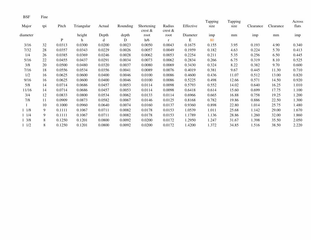
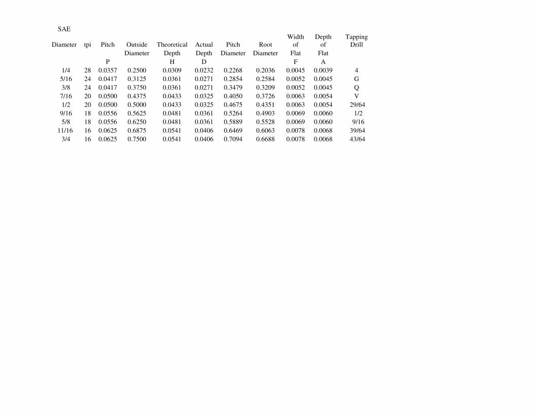
Thread Data.

Please note that the figures given in the charts have been worked out from first principles and will NOT be exactly the same as those

quoted in the ISO standards. The differences are usually only 1/10ths of thou.

Tables of threads are usually given in handy reference books but it is not generally known that all threads are based on a set formula

for each thread.

Below is the formula for each thread and each type has a link to an WinZip Excel spreadsheet.. These charts are interactive and will

give true thread details for any size required. By entering the required %age full thread a correct tapping size can be obtained. Select

your nearest (very close) drill size. You may need to "unprotect" the data first.

Tapping Sizes

Some confusion often arises when different drill sizes are given to tap the same female thread. The reason is quite simple. There is no

one drill size to tap a given hole !!

1) There may not be an exact drill size for the core diameter required. We use the nearest one available.

2) In practice it is usual to drill & tap to give a thread which is not 100% full thread. Figures such as 70%, 75%, 80% full thread are

very rarely quoted but must have been used in the initial calculations

3) It is often desirable for the internal thread to have the crests flat rather than have the full perfect radiused form. This prevents

threads binding & prolongs tool life.

4) When tapping hard material such as Stainless Steel an 70% full thread (female) used with a 100% male bolt may be 100% OK. Use

a No.2 tap as less cutting length on the flutes reduces tap stress. Also consider modern coated taps.

5) It may be virtually impossible to tap 100% full thread anyway without risking a broken tap. If in doubt drill a tad bigger and use a

good fitting male thread with more thread length engaged.

6) As with all things mechanical, tolerances must be mentioned. Tolerances are mainly the province of mass production &

interchangeability. For our one off's, if it fits to YOUR SATISFACTION its OK. Thread tolerances can be a very complicated subject

& need sophisticated gauging equipment. Taps are made in a range of tolerances. Class 2 is the normal specification. Carbon taps are

usually cheaper & manufactured to wider tolerances. All taps are manufactured as "plus on basic" to allow for wear in production. As

the tap wears the thread moves towards nominal.

7) Always use very sharp taps & dies & lubricate well.

8) It is virtually impossible to tap a hole 100% vertical by eye. Whenever possible, use a jig to ensure that the tap is vertical. Use of a

tapping jig will virtually eliminate broken taps.

Health & Safety Notice

UNC & Whitworth nuts & bolts were interchangeable. This is complete rubbish & whilst some sizes are superficially the same ie:

Pitch & Diameter, the Thread Angle IS NOT.(60/55) This means that all the load is directed onto the thread crests and roots and not

full flank contact. DO NOT ATTEMPT TO MIX THE TWO. If in doubt throw away. One way to tell a UNF /UNC thread is to look

for joined up circles on the flats of the nuts/bolts. ie: OOOOOO This is NOT however a 100% guide. I have also noticed UNF/UNC

forged into the head. Another way is to use the Across Flats dimension. This is unique to UNC fasteners, it is not a whole metric size

nor is it the same as the equivalent Whitworth fastener. Non of these methods are 100% reliable. Use a proper thread gauge if possible

or try to measure the core diameters with the correct thread micrometer. If the fit is tight or loose it is probably an incorrect mix. Also

note that Stainless Steel fittings ARE NOT AS STRONG as HIGH TENSILE steel bolts etc. DO NOT USE in highly stressed

applications where bolt failure could lead to an accident without full professional advice as to grade, thread form and suitable

diameter. If in doubt always use the Manufacturer's correct part for the relevant application.

BSW (British Standard Whitworth)

P = Pitch = 1/Number of threads per inch (tpi)

h = Angular Depth = 0.960491 x P

D = Depth of Rounding = 0.073917 x P

h/6 = Shortening = 0.160083 x P

d = Actual Depth = 0.640327 x P

r = Radius at the Crest & Root = 0.137329 x P

C = Core diameter = Major Diameter - 1.280654 x P

Effective or Pitch Diameter = Major Diameter - .640327 x P

BSW Whitworth

Major tpi Pitch Triangular Actual Rounding Shortening Radius Effective Tapping

Tapping

size Clearance Clearance

Across

flats

diameter height Depth depth

crest &

root

crest &

root Diameter

size

imp size mm imp mm imp

P h d D h/6 r E 80

1/16 60 0.0167 0.0160 0.0107 0.0012 0.0027 0.0023 0.0518 0.0454 1.15 0.065 1.65

3/32 48 0.0208 0.0200 0.0133 0.0015 0.0033 0.0029 0.0804 0.0724 1.84 0.098 2.50

1/8 40 0.0250 0.0240 0.0160 0.0018 0.0040 0.0034 0.1090 0.0994 2.52 0.130 3.30

5/32 32 0.0313 0.0300 0.0200 0.0023 0.0050 0.0043 0.1362 0.1242 3.16 0.161 4.10

3/16 24 0.0417 0.0400 0.0267 0.0031 0.0067 0.0057 0.1608 0.1448 3.68 0.193 4.90 0.340

7/32 24 0.0417 0.0400 0.0267 0.0031 0.0067 0.0057 0.1921 0.1761 4.47 0.224 5.70 0.413

1/4 20 0.0500 0.0480 0.0320 0.0037 0.0080 0.0069 0.2180 0.1988 5.05 0.256 6.50 0.445

5/16 18 0.0556 0.0534 0.0356 0.0041 0.0089 0.0076 0.2769 0.2556 6.49 0.319 8.10 0.525

3/8 16 0.0625 0.0600 0.0400 0.0046 0.0100 0.0086 0.3350 0.3110 7.90 0.382 9.70 0.600

7/16 14 0.0714 0.0686 0.0457 0.0053 0.0114 0.0098 0.3918 0.3643 9.25 0.445 11.30 0.710

1/2 12 0.0833 0.0800 0.0534 0.0062 0.0133 0.0114 0.4466 0.4146 10.53 0.512 13.00 0.820

9/16 12 0.0833 0.0800 0.0534 0.0062 0.0133 0.0114 0.5091 0.4771 12.12 0.571 14.50 0.920

5/8 11 0.0909 0.0873 0.0582 0.0067 0.0146 0.0125 0.5668 0.5319 13.51 0.640 16.25 1.100

11/16 11 0.0909 0.0873 0.0582 0.0067 0.0146 0.0125 0.6293 0.5944 15.10 0.699 17.75 1.200

3/4 10 0.1000 0.0960 0.0640 0.0074 0.0160 0.0137 0.6860 0.6475 16.45 0.758 19.25 1.300

13/16 10 0.1000 0.0960 0.0640 0.0074 0.0160 0.0137 0.7485 0.7100 18.04 0.827 21.00 1.390

7/8 9 0.1111 0.1067 0.0711 0.0082 0.0178 0.0153 0.8039 0.7612 19.33 0.886 22.50 1.480

15/16 9 0.1111 0.1067 0.0711 0.0082 0.0178 0.0153 0.8664 0.8237 20.92 0.945 24.00 1.575

1 8 0.1250 0.1201 0.0800 0.0092 0.0200 0.0172 0.9200 0.8719 22.15 1.014 25.75 1.670

1 1/8 7 0.1429 0.1372 0.0915 0.0106 0.0229 0.0196 1.0335 0.9786 24.86 1.142 29.00 1.860

1 1/4 7 0.1429 0.1372 0.0915 0.0106 0.0229 0.0196 1.1585 1.1036 28.03 1.260 32.00 2.050

1 3/8 6 0.1667 0.1601 0.1067 0.0123 0.0267 0.0229 1.2683 1.2042 30.59 1.398 35.50 2.220

1 1/2 6 0.1667 0.1601 0.1067 0.0123 0.0267 0.0229 1.3933 1.3292 33.76 1.516 38.50 2.410

1 5/8 5 0.2000 0.1921 0.1281 0.0148 0.0320 0.0275 1.4969 1.4201 36.07 1.634 41.50 2.580

1 3/4 5 0.2000 0.1921 0.1281 0.0148 0.0320 0.0275 1.6219 1.5451 39.25 1.772 45.00 2.760

1 7/8 4.5 0.2222 0.2134 0.1423 0.0164 0.0356 0.0305 1.7327 1.6473 41.84 1.890 48.00 2.962

2 4.5 0.2222 0.2134 0.1423 0.0164 0.0356 0.0305 1.8577 1.7723 45.02 2.008 51.00 3.150

BSF (British Standard Fine)

P = Pitch = 1/Number of threads per inch (tpi)

h = Angular Depth = 0.960491 x P

D = Depth of Rounding = 0.073917 x P

h/6 = Shortening = 0.160083 x P

d = Actual Depth = 0.640327 x P

r = Radius at the Crest & Root = 0.137329 x P

C = Core diameter = Major Diameter - 1.280654 x P

Effective or Pitch Diameter = Major Diameter - .640327 x P

BSF Fine

Major tpi Pitch Triangular Actual Rounding Shortening Radius Effective

Tapping

size

Tapping

size Clearance Clearance

Across

flats

diameter height Depth depth

crest &

root

crest &

root Diameter imp mm imp mm imp

P h d D h/6 r E 80

3/16 32 0.0313 0.0300 0.0200 0.0023 0.0050 0.0043 0.1675 0.155 3.95 0.193 4.90 0.340

7/32 28 0.0357 0.0343 0.0229 0.0026 0.0057 0.0049 0.1959 0.182 4.63 0.224 5.70 0.413

1/4 26 0.0385 0.0369 0.0246 0.0028 0.0062 0.0053 0.2254 0.211 5.35 0.256 6.50 0.445

5/16 22 0.0455 0.0437 0.0291 0.0034 0.0073 0.0062 0.2834 0.266 6.75 0.319 8.10 0.525

3/8 20 0.0500 0.0480 0.0320 0.0037 0.0080 0.0069 0.3430 0.324 8.22 0.382 9.70 0.600

7/16 18 0.0556 0.0534 0.0356 0.0041 0.0089 0.0076 0.4019 0.381 9.67 0.445 11.30 0.710

1/2 16 0.0625 0.0600 0.0400 0.0046 0.0100 0.0086 0.4600 0.436 11.07 0.512 13.00 0.820

9/16 16 0.0625 0.0600 0.0400 0.0046 0.0100 0.0086 0.5225 0.498 12.66 0.571 14.50 0.920

5/8 14 0.0714 0.0686 0.0457 0.0053 0.0114 0.0098 0.5793 0.552 14.02 0.640 16.25 1.010

11/16 14 0.0714 0.0686 0.0457 0.0053 0.0114 0.0098 0.6418 0.614 15.60 0.699 17.75 1.100

3/4 12 0.0833 0.0800 0.0534 0.0062 0.0133 0.0114 0.6966 0.665 16.88 0.758 19.25 1.200

7/8 11 0.0909 0.0873 0.0582 0.0067 0.0146 0.0125 0.8168 0.782 19.86 0.886 22.50 1.300

1 10 0.1000 0.0960 0.0640 0.0074 0.0160 0.0137 0.9360 0.898 22.80 1.014 25.75 1.480

1 1/8 9 0.1111 0.1067 0.0711 0.0082 0.0178 0.0153 1.0539 1.011 25.68 1.142 29.00 1.670

1 1/4 9 0.1111 0.1067 0.0711 0.0082 0.0178 0.0153 1.1789 1.136 28.86 1.260 32.00 1.860

1 3/8 8 0.1250 0.1201 0.0800 0.0092 0.0200 0.0172 1.2950 1.247 31.67 1.398 35.50 2.050

1 1/2 8 0.1250 0.1201 0.0800 0.0092 0.0200 0.0172 1.4200 1.372 34.85 1.516 38.50 2.220

ME (Model Engineer)

P = Pitch = 1/Number of threads per inch (tpi)

h = Angular Depth = 0.960491 x P

D = Depth of Rounding = 0.073917 x P

h/6 = Shortening = 0.160083 x P

d = Actual Depth = 0.640327 x P

r = Radius at the Crest & Root = 0.137329 x P

C = Core diameter = Major Diameter - 1.280654 x P

Effective or Pitch Diameter = Major Diameter - .640327 x P

MODEL ENGINEER

Pitch Triangular Actual Rounding Shortening Radius Effective

Tapping

size

Tapping

size Clearance Clearance

Across

flats

height Depth depth

crest &

root

crest &

root Diameter imp mm imp mm imp

P h d D h/6 r E 80

based on

BA

0.0313 0.0300 0.0200 0.0023 0.0050 0.0043 0.1050 0.0930 2.36 0.135 3.43 0.219

0.0313 0.0300 0.0200 0.0023 0.0050 0.0043 0.1362 0.1242 3.16 0.166 4.22 0.273

0.0313 0.0300 0.0200 0.0023 0.0050 0.0043 0.1675 0.1555 3.95 0.198 5.02 0.328

0.0313 0.0300 0.0200 0.0023 0.0050 0.0043 0.1987 0.1867 4.74 0.229 5.81 0.383

0.0313 0.0300 0.0200 0.0023 0.0050 0.0043 0.2300 0.2180 5.54 0.260 6.60 0.438

0.0313 0.0300 0.0200 0.0023 0.0050 0.0043 0.2612 0.2492 6.33 0.291 7.40 0.492

0.0313 0.0300 0.0200 0.0023 0.0050 0.0043 0.2925 0.2805 7.12 0.323 8.19 0.547

0.0313 0.0300 0.0200 0.0023 0.0050 0.0043 0.3550 0.3430 8.71 0.385 9.78 0.656

0.0313 0.0300 0.0200 0.0023 0.0050 0.0043 0.4175 0.4055 10.30 0.448 11.37 0.766

0.0313 0.0300 0.0200 0.0023 0.0050 0.0043 0.4800 0.4680 11.89 0.510 12.95 0.875

0.0250 0.0240 0.0160 0.0018 0.0040 0.0034 0.1090 0.0994 2.52 0.135 3.43 0.219

0.0250 0.0240 0.0160 0.0018 0.0040 0.0034 0.1402 0.1306 3.32 0.166 4.22 0.273

0.0250 0.0240 0.0160 0.0018 0.0040 0.0034 0.1715 0.1619 4.11 0.198 5.02 0.328

0.0250 0.0240 0.0160 0.0018 0.0040 0.0034 0.2027 0.1931 4.91 0.229 5.81 0.383

0.0250 0.0240 0.0160 0.0018 0.0040 0.0034 0.2340 0.2244 5.70 0.260 6.60 0.438

0.0250 0.0240 0.0160 0.0018 0.0040 0.0034 0.2652 0.2556 6.49 0.291 7.40 0.492

0.0250 0.0240 0.0160 0.0018 0.0040 0.0034 0.2965 0.2869 7.29 0.323 8.19 0.547

0.0250 0.0240 0.0160 0.0018 0.0040 0.0034 0.3590 0.3494 8.87 0.385 9.78 0.656

0.0250 0.0240 0.0160 0.0018 0.0040 0.0034 0.4215 0.4119 10.46 0.448 11.37 0.766

0.0250 0.0240 0.0160 0.0018 0.0040 0.0034 0.4840 0.4744 12.05 0.510 12.95 0.875

BA (British Association)

P = Pitch = 1/Number of threads per inch (tpi)

h = Triangular height = 1.1363365 x P

d = Actual Depth = 0.60000 x P

t = Shortening = 0.2681688 x P

r = Radius at the Crest & Root = 0.1808346 x P

Effective or Pitch Diameter = Major Diameter - 0.6000 x P (d)

C = Core diameter = Major Diameter - 1.2000 x P (2d)

Nuts and Bolts across flats is nominally 1.75 x Major Diameter

For Model Engineering purposes nuts and bolts are obtainable

with the hexagon heads one size less across flats, this gives a better scale effect

.

British Association

BA Major tpi Pitch Triangular Actual Shortening Radius Effective Tapping Tapping Clearance Clearance

Across

flats

Across

Flats

number diameter

Ref.

Only height depth

crest &

root

crest &

root Diameter

size

imp

size

mm imp mm imp mm

P h d t r e 75

0 0.2362 25.3807 0.0394 0.0448 0.0236 0.0106 0.0071 0.2126 0.2007 5.10 0.240 6.10 0.413 10.50

1 0.2087 28.2486 0.0354 0.0402 0.0212 0.0096 0.0064 0.1875 0.1768 4.49 0.213 5.40 0.365 9.28

2 0.1850 31.3480 0.0319 0.0362 0.0191 0.0086 0.0058 0.1659 0.1563 3.97 0.189 4.80 0.324 8.22

3 0.1614 34.8432 0.0287 0.0326 0.0172 0.0077 0.0052 0.1442 0.1356 3.44 0.165 4.20 0.282 7.17

4 0.1417 38.4615 0.0260 0.0295 0.0156 0.0070 0.0047 0.1261 0.1183 3.00 0.146 3.70 0.248 6.30

5 0.1260 43.1034 0.0232 0.0264 0.0139 0.0063 0.0042 0.1121 0.1051 2.67 0.130 3.30 0.221 5.60

6 0.1102 47.8469 0.0209 0.0237 0.0125 0.0056 0.0038 0.0977 0.0914 2.32 0.114 2.90 0.193 4.90

7 0.0984 52.9101 0.0189 0.0215 0.0113 0.0051 0.0034 0.0871 0.0814 2.07 0.102 2.60 0.172 4.37

8 0.0866 59.1716 0.0169 0.0192 0.0101 0.0046 0.0031 0.0765 0.0714 1.81 0.089 2.25 0.152 3.85

9 0.0748 64.9351 0.0154 0.0175 0.0092 0.0042 0.0028 0.0656 0.0609 1.55 0.077 1.95 0.131 3.32

10 0.0669 72.4638 0.0138 0.0157 0.0083 0.0037 0.0025 0.0586 0.0545 1.38 0.069 1.75 0.117 2.97

11 0.0591 81.9672 0.0122 0.0139 0.0073 0.0033 0.0022 0.0518 0.0481 1.22 0.063 1.60 0.103 2.63

12 0.0511 90.9091 0.0110 0.0125 0.0066 0.0030 0.0020 0.0445 0.0412 1.05 0.055 1.40 0.089 2.27

13 0.0472 102.0408 0.0098 0.0111 0.0059 0.0026 0.0018 0.0413 0.0384 0.97 0.051 1.30 0.083 2.10

14 0.0394 109.8901 0.0091 0.0103 0.0055 0.0025 0.0016 0.0339 0.0312 0.79 0.043 1.10 0.069 1.75

15 0.0354 120.4819 0.0083 0.0094 0.0050 0.0022 0.0015 0.0304 0.0279 0.71 0.039 0.98 0.062 1.57

16 0.0311 133.3333 0.0075 0.0085 0.0045 0.0020 0.0014 0.0266 0.0244 0.62 0.035 0.88 0.054 1.38

ISO Metric Fine

ISO Metric Coarse

P = Pitch = 1/Number of threads per inch (tpi)

H = Angular Depth = 0.866025 x P

H/8 = Shortening of major dia = 0.108253 x P

H/4 = Shortening of minor dia = 0.216506 x P

d = Actual Depth = 0.541266 x P

r = Radius at the Root = 0.1443 x P

Hn = Basic height of Internal Thread = 0.54127 x Hs = Basic height of External Thread = 0.61344 x P

Note: The form of the Metric Series of Threads varies between Internal & External Threads, in particular the root and crest details.

This allows for flat (truncated) or radiused forms. Engineers requiring more specific information should refer to the relevant ISO

Standards. This data base is far to small to fully cover this subject.

ISO

Metric

Fine

for

Model

Engineers

Major tpi Pitch Triangular Actual Shortening Shortening Effective

Tapping

size

Tapping

Size Clearance Clearance

Across

flats

diameter Ref. only Height Depth Major Minor Diameter mm imp mm imp mm

P H d H/8 H/6 E

3.0 50.80 0.50 0.433 0.271 0.054 0.108 2.675 2.60 0.102 3.10 0.122 5.500

4.0 50.80 0.50 0.433 0.271 0.054 0.108 3.675 3.60 0.142 4.10 0.161 7.000

4.5 50.80 0.50 0.433 0.271 0.054 0.108 4.175 4.10 0.161 4.60 0.181 7.500

5.0 50.80 0.50 0.433 0.271 0.054 0.108 4.675 4.60 0.181 5.10 0.201 8.000

5.5 50.80 0.50 0.433 0.271 0.054 0.108 5.175 5.10 0.201 5.60 0.220 9.000

6.0 50.80 0.50 0.433 0.271 0.054 0.108 5.675 5.60 0.220 6.10 0.240 10.000

4.5 33.87 0.75 0.650 0.406 0.081 0.162 4.013 3.90 0.154 4.60 0.181 7.500

6.0 33.87 0.75 0.650 0.406 0.081 0.162 5.513 5.40 0.213 6.10 0.240 10.000

7.0 33.87 0.75 0.650 0.406 0.081 0.162 6.513 6.40 0.252 7.10 0.280 11.000

8.0 33.87 0.75 0.650 0.406 0.081 0.162 7.513 7.30 0.287 8.10 0.319 13.000

10.0 33.87 0.75 0.650 0.406 0.081 0.162 9.513 9.30 0.366 10.20 0.402 17.000

12.0 33.87 0.75 0.650 0.406 0.081 0.162 11.513 11.30 0.445 12.20 0.480 19.000

10.0 25.40 1.00 0.866 0.541 0.108 0.217 9.350 9.10 0.358 10.20 0.402 17.000

12.0 25.40 1.00 0.866 0.541 0.108 0.217 11.350 11.10 0.437 12.20 0.480 19.000

14.0 25.40 1.00 0.866 0.541 0.108 0.217 13.350 13.10 0.516 14.20 0.559 22.000

16.0 25.40 1.00 0.866 0.541 0.108 0.217 15.350 15.10 0.594 16.20 0.638 24.000

18.0 25.40 1.00 0.866 0.541 0.108 0.217 17.350 17.10 0.673 18.20 0.717 27.000

20.0 25.40 1.00 0.866 0.541 0.108 0.217 19.350 19.10 0.752 20.20 0.795 30.000

ISO

Metric

Coarse

Major tpi Pitch Triangular Actual Shortening Shortening Effective

Tapping

size

Tapping

Size Clearance Clearance

Across

flats

diameter Ref. only Height Depth Major Minor Diameter mm imp mm imp mm

P H d H/8 H/4 E

1.0 101.60 0.25 0.217 0.135 0.027 0.054 0.838 0.75 0.030 1.05 0.041

1.1 101.60 0.25 0.217 0.135 0.027 0.054 0.938 0.85 0.033 1.15 0.045

1.2 101.60 0.25 0.217 0.135 0.027 0.054 1.038 0.95 0.037 1.25 0.049

1.4 84.67 0.30 0.260 0.162 0.032 0.065 1.205 1.10 0.043 1.45 0.057

1.6 72.57 0.35 0.303 0.189 0.038 0.076 1.373 1.25 0.049 1.65 0.065

1.8 72.57 0.35 0.303 0.189 0.038 0.076 1.573 1.45 0.057 1.85 0.073

2.0 63.50 0.40 0.346 0.217 0.043 0.087 1.740 1.60 0.063 2.05 0.081 4.000

2.2 56.44 0.45 0.390 0.244 0.049 0.097 1.908 1.75 0.069 2.25 0.089 4.500

2.5 56.44 0.45 0.390 0.244 0.049 0.097 2.208 2.05 0.081 2.60 0.102 5.000

3.0 50.80 0.50 0.433 0.271 0.054 0.108 2.675 2.50 0.098 3.10 0.122 5.500

3.5 42.33 0.60 0.520 0.325 0.065 0.130 3.110 2.90 0.114 3.60 0.142 6.000

4.0 36.29 0.70 0.606 0.379 0.076 0.152 3.545 3.30 0.130 4.10 0.161 7.000

4.5 33.87 0.75 0.650 0.406 0.081 0.162 4.013 3.70 0.146 4.60 0.181 7.500

5.0 31.75 0.80 0.693 0.433 0.087 0.173 4.480 4.20 0.165 5.10 0.201 8.000

6.0 25.40 1.00 0.866 0.541 0.108 0.217 5.350 5.00 0.197 6.10 0.240 10.000

7.0 25.40 1.00 0.866 0.541 0.108 0.217 6.350 6.00 0.236 7.20 0.283 11.000

8.0 20.32 1.25 1.083 0.677 0.135 0.271 7.188 6.80 0.268 8.20 0.323 13.000

9.0 20.32 1.25 1.083 0.677 0.135 0.271 8.188 7.80 0.307 9.20 0.362 15.000

10.0 16.93 1.50 1.299 0.812 0.162 0.325 9.026 8.50 0.335 10.20 0.402 17.000

11.0 16.93 1.50 1.299 0.812 0.162 0.325 10.026 9.50 0.374 11.20 0.441 18.000

12.0 14.51 1.75 1.516 0.947 0.189 0.379 10.863 10.20 0.402 12.20 0.480 19.000

14.0 12.70 2.00 1.732 1.083 0.217 0.433 12.701 12.00 0.472 14.25 0.561 22.000

16.0 12.70 2.00 1.732 1.083 0.217 0.433 14.701 14.00 0.551 16.25 0.640 24.000

18.0 10.16 2.50 2.165 1.353 0.271 0.541 16.376 15.50 0.610 18.25 0.719 27.000

20.0 10.16 2.50 2.165 1.353 0.271 0.541 18.376 17.50 0.689 20.25 0.797 30.000

Unified National Fine (UNF)

Unified National Coarse (UNC)

P = Pitch = 1/Number of threads per inch (tpi)

H = Angular Depth = 0.866025 x P

H/8 = Shortening of major dia = 0.108253 x P

H/4 = Shortening of minor dia = 0.216506 x P

d = Actual Depth = 0.541266 x P

r = Radius at the Root = 0.1443 x P

Hn = Basic height of Internal Thread = 0.54127 x PHs = Basic height of External Thread = 0.61344 x P

Unified

Fine

No. tpi Pitch Major Triangular Actual Shortening Shortening Radius

Tapping

Size

Tapping

Size Clearance Clearance

Across

Flats

Across

flats

Size Diameter Height Depth Major Minor mm imp mm imp imp fraction

P H d H/8 H/4 r

0 80 0.0125 0.0600 0.0108 0.00677 0.00135 0.00271 0.0018 1.25 0.049 1.60 0.063 0.1563 5/32

1 72 0.0139 0.0730 0.0120 0.00752 0.00150 0.00301 0.0020 1.55 0.061 1.95 0.077 0.1563 5/32

2 64 0.0156 0.0860 0.0135 0.00846 0.00169 0.00338 0.0023 1.90 0.075 2.30 0.091 0.1875 3/16

3 56 0.0179 0.0990 0.0155 0.00967 0.00193 0.00387 0.0026 2.15 0.085 2.65 0.104 0.1875 3/16

4 48 0.0208 0.1120 0.0180 0.01128 0.00226 0.00451 0.0030 2.40 0.094 2.95 0.116 0.2500 1/4

5 44 0.0227 0.1250 0.0197 0.01230 0.00246 0.00492 0.0033 2.70 0.106 3.30 0.130 0.3125 5/16

6 40 0.0250 0.1380 0.0217 0.01353 0.00271 0.00541 0.0036 2.95 0.116 3.60 0.142 0.3125 5/16

8 36 0.0278 0.1640 0.0241 0.01504 0.00301 0.00601 0.0040 3.50 0.138 4.30 0.169 0.3440 11/32

10 32 0.0313 0.1900 0.0271 0.01691 0.00338 0.00677 0.0045 4.10 0.161 4.90 0.193 0.3750 3/8

12 28 0.0357 0.2160 0.0309 0.01933 0.00387 0.00773 0.0052 4.70 0.185 5.60 0.220 0.4375 7/16

1/4 28 0.0357 0.2500 0.0309 0.01933 0.00387 0.00773 0.0052 5.50 0.217 6.50 0.256 0.4375 7/16

5/16 24 0.0417 0.3125 0.0361 0.02255 0.00451 0.00902 0.0060 6.90 0.272 8.10 0.319 0.5000 1/2

3/8 24 0.0417 0.3750 0.0361 0.02255 0.00451 0.00902 0.0060 8.50 0.335 9.70 0.382 0.5625 9/16

7/16 20 0.0500 0.4375 0.0433 0.02706 0.00541 0.01083 0.0072 9.90 0.390 11.30 0.445 0.6250 5/8

1/2 20 0.0500 0.5000 0.0433 0.02706 0.00541 0.01083 0.0072 11.50 0.453 13.00 0.512 0.7500 3/4

9/16 18 0.0556 0.5625 0.0481 0.03007 0.00601 0.01203 0.0080 12.90 0.508 14.50 0.571 0.8125 13/16

5/8 18 0.0556 0.6250 0.0481 0.03007 0.00601 0.01203 0.0080 14.50 0.571 16.25 0.640 0.9375 15/16

3/4 16 0.0625 0.7500 0.0541 0.03383 0.00677 0.01353 0.0090 17.50 0.689 19.25 0.758 1.1250 1 1/8

7/8 14 0.0714 0.8750 0.0619 0.03866 0.00773 0.01546 0.0103 20.40 0.803 22.50 0.886 1.3125 1 5/16

1 12 0.0833 1.0000 0.0722 0.04511 0.00902 0.01804 0.0120 23.25 0.915 25.75 1.014 1.5000 1 1/2

1 1/8 12 0.0833 1.1250 0.0722 0.04511 0.00902 0.01804 0.0120 26.50 1.043 29.00 1.142 1.6875 1 11/16

1 1/4 12 0.0833 1.2500 0.0722 0.04511 0.00902 0.01804 0.0120 29.50 1.161 32.00 1.260 1.8750 1 7/8

1 3/8 12 0.0833 1.3750 0.0722 0.04511 0.00902 0.01804 0.0120 32.75 1.289 35.50 1.398 2.0625 2 1/16

1 1/2 12 0.0833 1.5000 0.0722 0.04511 0.00902 0.01804 0.0120 36.00 1.417 38.50 1.516 2.2500 2 1/4

Unified Coarse

No. tpi Pitch Major Triangular Actual Shortening Shortening Radius

Tapping

Size

Tapping

Size Clearance Clearance

Across

flats

Across

flats

Size Diameter Height Depth Major Minor mm imp mm imp imp fraction

P H d H/8 H/4 r

1 64 0.0156 0.0730 0.0135 0.00846 0.00169 0.00338 0.0023 1.55 0.061 1.95 0.077 0.1563 5/32

2 56 0.0179 0.0860 0.0155 0.00967 0.00193 0.00387 0.0026 1.85 0.073 2.30 0.091 0.1870 3/16

3 48 0.0208 0.0990 0.0180 0.01128 0.00226 0.00451 0.0030 2.10 0.083 2.65 0.104 0.1870 3/16

4 40 0.0250 0.1120 0.0217 0.01353 0.00271 0.00541 0.0036 2.35 0.093 2.95 0.116 0.2500 1/4

5 40 0.0250 0.1250 0.0217 0.01353 0.00271 0.00541 0.0036 2.65 0.104 3.30 0.130 0.3125 5/16

6 32 0.0313 0.1380 0.0271 0.01691 0.00338 0.00677 0.0045 2.85 0.112 3.60 0.142 0.3125 5/16

8 32 0.0313 0.1640 0.0271 0.01691 0.00338 0.00677 0.0045 3.50 0.138 4.30 0.169 0.3440 11/32

10 24 0.0417 0.1900 0.0361 0.02255 0.00451 0.00902 0.0060 3.90 0.154 4.90 0.193 0.3750 9/32

12 24 0.0417 0.2160 0.0361 0.02255 0.00451 0.00902 0.0060 4.50 0.177 5.60 0.220 0.4375 7/16

1/4 20 0.0500 0.2500 0.0433 0.02706 0.00541 0.01083 0.0072 5.10 0.201 6.50 0.256 0.4375 7/16

5/16 18 0.0556 0.3125 0.0481 0.03007 0.00601 0.01203 0.0080 6.60 0.260 8.10 0.319 0.5000 1/2

3/8 16 0.0625 0.3750 0.0541 0.03383 0.00677 0.01353 0.0090 8.00 0.315 9.70 0.382 0.5625 9/16

7/16 14 0.0714 0.4375 0.0619 0.03866 0.00773 0.01546 0.0103 9.40 0.370 11.30 0.445 0.6250 5/8

1/2 13 0.0769 0.5000 0.0666 0.04164 0.00833 0.01665 0.0111 10.80 0.425 13.00 0.512 0.7500 3/4

9/16 12 0.0833 0.5625 0.0722 0.04511 0.00902 0.01804 0.0120 12.20 0.480 14.50 0.571 0.8125 13/16

5/8 11 0.0909 0.6250 0.0787 0.04921 0.00984 0.01968 0.0131 13.50 0.531 16.25 0.640 0.9375 15/16

3/4 10 0.1000 0.7500 0.0866 0.05413 0.01083 0.02165 0.0144 16.50 0.650 19.25 0.758 1.1250 1 1/8

7/8 9 0.1111 0.8750 0.0962 0.06014 0.01203 0.02406 0.0160 19.50 0.768 22.50 0.886 1.3125 1 5/16

1 8 0.1250 1.0000 0.1083 0.06766 0.01353 0.02706 0.0180 22.25 0.876 25.75 1.014 1.5000 1 1/2

1 1/8 7 0.1429 1.1250 0.1237 0.07732 0.01546 0.03093 0.0206 25.00 0.984 29.00 1.142 1.6875 1 11/16

1 1/4 7 0.1429 1.2500 0.1237 0.07732 0.01546 0.03093 0.0206 28.00 1.102 32.00 1.260 1.8750 1 7/8

1 3/8 6 0.1667 1.3750 0.1443 0.09021 0.01804 0.03608 0.0241 30.75 1.211 35.50 1.398 2.0625 2 1/16

1 1/2 6 0.1667 1.5000 0.1443 0.09021 0.01804 0.03608 0.0241 34.00 1.339 38.50 1.516 2.2500 2 1/4

1 3/4 5 0.2000 1.7500 0.1732 0.10825 0.02165 0.04330 0.0289 39.50 1.555 45.00 1.772 2.6250 2 5/8

2 4.5 0.2222 2.0000 0.1925 0.12028 0.02406 0.04811 0.0321 45.00 1.772 51.00 2.008 3.0000 3

United States Standard (USS)

United States Form (USF)

Society of Automobile Engineers (SAE)

This form also occurs in the National Coarse (N.C.) and National Fine (N.F.) series of threads.

It is very similar to the UNF and UNC threads but has a Flat Root & Crest.

P = Pitch = 1/Number of threads per inch (tpi)

H = Theoretical Depth = 0.866 x P

D = Actual Depth = 0.6495 x P

F = Width of Flat = 0.125 x PA = Depth of Flat = 0.108 x P

USS

Diameter tpi Pitch Outside Theoretical Actual Pitch Root

Width

of

Depth

of

Tapping

Drill

Diameter Depth Depth Diameter Diameter Flat Flat

P H D F A

1/16 64 0.0156 0.0625 0.0135 0.0101 0.0524 0.0422 0.0020 0.0017 56

5/64 60 0.0167 0.0781 0.0144 0.0108 0.0673 0.0565 0.0021 0.0018 53

3/32 50 0.0200 0.0938 0.0173 0.0130 0.0808 0.0678 0.0025 0.0022 50

7/64 48 0.0208 0.1094 0.0180 0.0135 0.0958 0.0823 0.0026 0.0023 44

1/8 40 0.0250 0.1250 0.0217 0.0162 0.1088 0.0925 0.0031 0.0027 41

9/64 40 0.0250 0.1406 0.0217 0.0162 0.1244 0.1082 0.0031 0.0027 34

5/32 36 0.0278 0.1563 0.0241 0.0180 0.1382 0.1202 0.0035 0.0030 1/8

11/64 32 0.0313 0.1719 0.0271 0.0203 0.1516 0.1313 0.0039 0.0034 29

3/16 24 0.0417 0.1875 0.0361 0.0271 0.1604 0.1334 0.0052 0.0045 29

13/64 24 0.0417 0.2031 0.0361 0.0271 0.1761 0.1490 0.0052 0.0045 24

7/32 24 0.0417 0.2188 0.0361 0.0271 0.1917 0.1646 0.0052 0.0045 19

15/64 24 0.0417 0.2344 0.0361 0.0271 0.2073 0.1803 0.0052 0.0045 13

1/4 20 0.0500 0.2500 0.0433 0.0325 0.2175 0.1851 0.0063 0.0054 12

5/16 18 0.0556 0.3125 0.0481 0.0361 0.2764 0.2403 0.0069 0.0060 D

3/8 16 0.0625 0.3750 0.0541 0.0406 0.3344 0.2938 0.0078 0.0068 N

7/16 14 0.0714 0.4375 0.0619 0.0464 0.3911 0.3447 0.0089 0.0077 S

1/2 13 0.0769 0.5000 0.0666 0.0500 0.4500 0.4001 0.0096 0.0083 13/32

9/16 12 0.0833 0.5625 0.0722 0.0541 0.5084 0.4543 0.0104 0.0090 15/32

5/8 11 0.0909 0.6250 0.0787 0.0590 0.5660 0.5069 0.0114 0.0098 33/64

11/16 11 0.0909 0.6875 0.0787 0.0590 0.6285 0.5694 0.0114 0.0098 37/64

3/4 10 0.1000 0.7500 0.0866 0.0650 0.6851 0.6201 0.0125 0.0108 5/8

USF

Diameter tpi Pitch Outside Theoretical Actual Pitch Root

Width

of

Depth

of

Tapping

Drill

Diameter Depth Depth Diameter Diameter Flat Flat

P H D F A

1/16 60 0.0167 0.0625 0.0144 0.0108 0.0517 0.0409 0.0021 0.0018 57

1/16 72 0.0139 0.0625 0.0120 0.0090 0.0535 0.0445 0.0017 0.0015 55

5/64 56 0.0179 0.0781 0.0155 0.0116 0.0665 0.0549 0.0022 0.0019 53

3/32 48 0.0208 0.0938 0.0180 0.0135 0.0802 0.0667 0.0026 0.0023 50

3/32 56 0.0179 0.0938 0.0155 0.0116 0.0822 0.0706 0.0022 0.0019 49

3/32 60 0.0167 0.0938 0.0144 0.0108 0.0829 0.0721 0.0021 0.0018 48

1/8 32 0.0313 0.1250 0.0271 0.0203 0.1047 0.0844 0.0039 0.0034 43

1/8 36 0.0278 0.1250 0.0241 0.0180 0.1070 0.0889 0.0035 0.0030 42

1/8 48 0.0208 0.1250 0.0180 0.0135 0.1115 0.0979 0.0026 0.0023 39

9/64 32 0.0313 0.1406 0.0271 0.0203 0.1203 0.1000 0.0039 0.0034 37

9/64 36 0.0278 0.1406 0.0241 0.0180 0.1226 0.1045 0.0035 0.0030 35

5/32 32 0.0313 0.1563 0.0271 0.0203 0.1360 0.1157 0.0039 0.0034 31

5/32 40 0.0250 0.1563 0.0217 0.0162 0.1400 0.1238 0.0031 0.0027 30

11/64 36 0.0278 0.1719 0.0241 0.0180 0.1538 0.1358 0.0035 0.0030 28

3/16 30 0.0333 0.1875 0.0289 0.0217 0.1659 0.1442 0.0042 0.0036 26

3/16 32 0.0313 0.1875 0.0271 0.0203 0.1672 0.1469 0.0039 0.0034 25

3/16 36 0.0278 0.1875 0.0241 0.0180 0.1695 0.1514 0.0035 0.0030 23

13/64 32 0.0313 0.2031 0.0271 0.0203 0.1828 0.1625 0.0039 0.0034 19

7/32 28 0.0357 0.2188 0.0309 0.0232 0.1956 0.1724 0.0045 0.0039 16

7/32 32 0.0313 0.2188 0.0271 0.0203 0.1985 0.1782 0.0039 0.0034 14

15/64 28 0.0357 0.2344 0.0309 0.0232 0.2112 0.1880 0.0045 0.0039 10

15/64 32 0.0313 0.2344 0.0271 0.0203 0.2141 0.1938 0.0039 0.0034 8

1/4 24 0.0417 0.2500 0.0361 0.0271 0.2229 0.1959 0.0052 0.0045 7

1/4 32 0.0313 0.2500 0.0271 0.0203 0.2297 0.2094 0.0039 0.0034 3

5/16 20 0.0500 0.3125 0.0433 0.0325 0.2800 0.2476 0.0063 0.0054 E

5/16 32 0.0313 0.3125 0.0271 0.0203 0.2922 0.2719 0.0039 0.0034 J

3/8 18 0.0556 0.3750 0.0481 0.0361 0.3389 0.3028 0.0069 0.0060 5/16

3/8 20 0.0500 0.3750 0.0433 0.0325 0.3425 0.3101 0.0063 0.0054 P

7/16 24 0.0417 0.4375 0.0361 0.0271 0.4104 0.3834 0.0052 0.0045 X

1/2 12 0.0833 0.5000 0.0722 0.0541 0.4459 0.3918 0.0104 0.0090 Y

1/2 24 0.0417 0.5000 0.0361 0.0271 0.4729 0.4459 0.0052 0.0045 29/64

5/8 12 0.0833 0.6250 0.0722 0.0541 0.5709 0.5168 0.0104 0.0090 17/32

11/16 12 0.0833 0.6875 0.0722 0.0541 0.6334 0.5793 0.0104 0.0090 19/32

3/4 12 0.0833 0.7500 0.0722 0.0541 0.6959 0.6418 0.0104 0.0090 21/32

SAE

Diameter tpi Pitch Outside Theoretical Actual Pitch Root

Width

of

Depth

of

Tapping

Drill

Diameter Depth Depth Diameter Diameter Flat Flat

P H D F A

1/4 28 0.0357 0.2500 0.0309 0.0232 0.2268 0.2036 0.0045 0.0039 4

5/16 24 0.0417 0.3125 0.0361 0.0271 0.2854 0.2584 0.0052 0.0045 G

3/8 24 0.0417 0.3750 0.0361 0.0271 0.3479 0.3209 0.0052 0.0045 Q

7/16 20 0.0500 0.4375 0.0433 0.0325 0.4050 0.3726 0.0063 0.0054 V

1/2 20 0.0500 0.5000 0.0433 0.0325 0.4675 0.4351 0.0063 0.0054 29/64

9/16 18 0.0556 0.5625 0.0481 0.0361 0.5264 0.4903 0.0069 0.0060 1/2

5/8 18 0.0556 0.6250 0.0481 0.0361 0.5889 0.5528 0.0069 0.0060 9/16

11/16 16 0.0625 0.6875 0.0541 0.0406 0.6469 0.6063 0.0078 0.0068 39/64

3/4 16 0.0625 0.7500 0.0541 0.0406 0.7094 0.6688 0.0078 0.0068 43/64

Sharp V-thread. (V)

Due to the sharp root and crest on this form, it is in theory, prone to stress cracking. The later UNF/UNC threads should be used where

possible, as these have rounded crests and roots, thus reducing stress concentration. The "V" thread is effectively obsolete. It still

remains a very easy thread to cut using single point tools. It is however NOT interchangeable with modern 60 degs Imperial threads.

UNF/UNC etc. Cutting tools, Taps and Dies etc. are no longer available.

The sides of the thread form an angle of 60 degs with each other. The top and bottom of the threads are theoretically sharp, but in

practice the crest has a slight flat equal to 1/25th x Pitch. This is removed after the thread is cut, thus reducing the actual diameter

slightly below nominal. (D) See chart details.

P = Pitch = 1/Number of threads per inch (tpi)

H = Theoretical Depth = 0.866 x P

D = Actual Depth with Crest Relief

A= Width of Flat = P/25 (Not in the Official Standards)

N = Depth of Flat

"V"

Diameter tpi Pitch Outside Actual Theoretical Pitch Root

Width

of

Depth

of

Tapping

Drill

Diameter Diameter Depth Diameter Diameter Flat Flat

Pitch D H A N

1/16 64 0.0156 0.0625 0.0614 0.0135 0.0490 0.0354 0.0006 0.0005 56

5/64 60 0.0167 0.0781 0.0770 0.0144 0.0637 0.0493 0.0007 0.0006 53

3/32 50 0.0200 0.0938 0.0924 0.0173 0.0764 0.0591 0.0008 0.0007 50

7/64 48 0.0208 0.1094 0.1079 0.0180 0.0913 0.0733 0.0008 0.0007 44

1/8 40 0.0250 0.1250 0.1233 0.0217 0.1034 0.0817 0.0010 0.0009 41

9/64 40 0.0250 0.1406 0.1389 0.0217 0.1190 0.0973 0.0010 0.0009 34

5/32 36 0.0278 0.1563 0.1543 0.0241 0.1322 0.1081 0.0011 0.0010 1/8

11/64 32 0.0313 0.1719 0.1697 0.0271 0.1448 0.1178 0.0013 0.0011 29

3/16 24 0.0417 0.1875 0.1846 0.0361 0.1514 0.1153 0.0017 0.0014 29

13/64 24 0.0417 0.2031 0.2002 0.0361 0.1670 0.1310 0.0017 0.0014 24

7/32 24 0.0417 0.2188 0.2159 0.0361 0.1827 0.1466 0.0017 0.0014 19

15/64 24 0.0417 0.2344 0.2315 0.0361 0.1983 0.1622 0.0017 0.0014 13

1/4 20 0.0500 0.2500 0.2465 0.0433 0.2067 0.1634 0.0020 0.0017 12

5/16 18 0.0556 0.3125 0.3087 0.0481 0.2644 0.2163 0.0022 0.0019 D

3/8 16 0.0625 0.3750 0.3707 0.0541 0.3209 0.2668 0.0025 0.0022 N

7/16 14 0.0714 0.4375 0.4326 0.0619 0.3756 0.3138 0.0029 0.0025 S

1/2 13 0.0769 0.5000 0.4947 0.0666 0.4334 0.3668 0.0031 0.0027 13/32

9/16 12 0.0833 0.5625 0.5567 0.0722 0.4903 0.4182 0.0033 0.0029 15/32

5/8 11 0.0909 0.6250 0.6187 0.0787 0.5463 0.4675 0.0036 0.0031 33/64

11/16 11 0.0909 0.6875 0.6812 0.0787 0.6088 0.5300 0.0036 0.0031 37/64

3/4 10 0.1000 0.7500 0.7431 0.0866 0.6634 0.5768 0.0040 0.0035 5/8

THREAD DATA CHARTS

PIPE THREAD -- BRITISH STANDARD PIPE PARALLEL -- BSPP/BSPF PIPE THREAD -- JAPANESE PIPE PARALLEL -- PF

British Pipe Thread ( Whitworth Form) -- Parallel (BSPP/BSPF)

Thread Designation

BSPP/BSPF

Nominal Size

BSPP/BSPF

Thread Form Type

Major Diameter

mm d=D

Pitch mm p

Threads per inch tpi

Pitch Diameter

mm d2=D2

Minor Diameter Male Thd.

d3

Thread Height

H1

Tap Drill

Diameter mm

G 1/8 1/8" BSPP/BSPF 9.728 0.907 28 9.147 8.566 0.581 8.7

G 1/4 1/4" BSPP/BSPF 13.157 1.337 19 12.301 11.445 0.856 11.6

G 3/8 3/8" BSPP/BSPF 16.662 1.337 19 15.806 14.95 0.856 15

G 1/2 1/2" BSPP/BSPF 20.955 1.814 14 19.793 18.631 1.162 19

G 5/8 5/8" BSPP/BSPF 22.911 1.814 14 21.749 20.587 1.162 20.75

G 3/4 3/4" BSPP/BSPF 26.441 1.814 14 25.279 24.117 1.162 24.5

G 7/8 7/8" BSPP/BSPF 30.201 1.814 14 29.039 27.877 1.162 28

G 1 1" BSPP/BSPF 33.249 2.309 11 31.77 30.291 1.479 30.5

G 1 1/8 1 1/8" BSPP/BSPF 37.897 2.309 11 36.418 34.939 1.479 35

G 1 1/4 1 1/4" BSPP/BSPF 41.91 2.309 11 40.431 38.952 1.479 39.5

G 1 3/8 1 3/8" BSPP/BSPF 44.323 2.309 11 42.844 41.365 1.479 41.5

G 1 1/2 1 1/2" BSPP/BSPF 47.803 2.309 11 46.324 44.845 1.479 45

G 1 3/4 1 3/4" BSPP/BSPF 53.746 2.309 11 52.267 50.788 1.479 51

G 2 2" BSPP/BSPF 59.614 2.309 11 58.135 56.656 1.479 57

G 2 1/4 2 1/4" BSPP/BSPF 65.71 2.309 11 64.231 62.752 1.479 63

G 2 1/2 2 1/2" BSPP/BSPF 75.184 2.309 11 73.705 72.226 1.479 72.5

G 2 3/4 2 3/4" BSPP/BSPF 81.534 2.309 11 80.055 78.576 1.479 79

G 3 3" BSPP/BSPF 87.884 2.309 11 86.405 84.926 1.479 85.5

G 3 1/4 3 1/4" BSPP/BSPF 93.98 2.309 11 92.501 91.022 1.479 91

G 3 1/2 3 1/2" BSPP/BSPF 100.33 2.309 11 98.351 97.372 1.479 97.75

G 3 3/4 3 3/4" BSPP/BSPF 106.68 2.309 11 105.201 103.722 1.479 104

G 4 4" BSPP/BSPF 113.03 2.309 11 111.55 110.072 1.479 110.5

G 4 1/2 4 1/2" BSPP/BSPF 125.73 2.309 11 124.251 122.772 1.479 123

G 5 5" BSPP/BSPF 138.43 2.309 11 136.951 135.472 1.479 136

G 5 1/2 5 1/2" BSPP/BSPF 151.13 2.309 11 149.651 148.172 1.479 148.5

G 6 6" BSPP/BSPF 163.83 2.309 11 162.351 160.872 1.479 161.5


Recommended