52
THREADED & BAYONET CONNECTORS FOR DEMANDING ENVIRONMENTS MILITARY AND COMMERCIAL AVIATION MIL - DTL - 26500 SERIES

THREADED & BAYONET CONNECTORS FOR DEMANDING ENVIRONMENTS
MILITARY AND COMMERCIAL AVIATION MIL - DTL - 26500 SERIES

2
This catalog defines rms MIL-DTL-26500, Series III Connectors. There are varieties of connectors within this cylindrical family, with the following options and characteristics available:
Two coupling styles: Bayonet and Threaded Plugs and Receptacles.
Both coupling styles inter-mate with MIL-DTL-83723 connectors (exception: shell size 8 threaded, does not mate with M83723 threaded).
Aluminum and passivated stainless steel versions.
A variety of mounting configurations.
A variety of material finishes are offered such as electroless nickel, olive drab cadmium and black anodizing. Other finishes are available with a commercial equivalent.
Alternate key/keyway positions prevent cross mating of adjacent connectors having the same insert arrangement.
Positive alignment of pin contacts by the lead in chamfers of the closed entry hard socket inserts, for select Boeing products.
The elastomer grommet is able to seal over a wide range of wire diameters and has a triple wire seal in each cavity.
The front release crimped contact retainer system features a retaining clip captivated by molded in shoulders of each contact cavity in the insulator. This produces a very stable contact.
Can be ordered by military, Boeing, or equivalent rms part numbers.
CONNECTORS FOR DEMANDING ENVIRONMENTS
THREADED AND BAYONET MILITARY AND COMMERCIAL AVIATION
8600 Evergreen Blvd. Minneapolis, MN 55433
763.786.1520 800.373.1520
Should you require more information or have a special application need arise, please contact:

3
Index
rms Connectors Overview . . . . . . . . . . 4General Operating FeaturesContact Ordering InformationContacts, Seal Plugs, and Tools
Shell & Insert Configuration . . . . . . . . . 5Available Inserts [diagrams]
rms Connectors Continued . . . . . . . . . . 7General Performance Characteristics
R0716 Series . . . . . . . . . . . . . . . . . . . . . . . 8Bayonet Plug, MIL-DTL-26500
R0717 Series . . . . . . . . . . . . . . . . . . . . . . 10Square Flange Bayonet Receptacle, MIL-DTL-26500
R0718 Series . . . . . . . . . . . . . . . . . . . . . . 12Threaded Plug, MIL-DTL-26500
R0719 Series . . . . . . . . . . . . . . . . . . . . . . 14Threaded Receptacle, MIL-DTL-26500
R0701 Series . . . . . . . . . . . . . . . . . . . . . . 16Bayonet Receptacle
R0700 Series . . . . . . . . . . . . . . . . . . . . . . 18Bayonet Plug, Vibration Resistant
R0700, R0712/R0701 Series . . . . . . . . . 20Test Data/Vibration
R0710 Series . . . . . . . . . . . . . . . . . . . . . . 23Threaded Plug, Self-locking
R0711 Series . . . . . . . . . . . . . . . . . . . . . . 26Threaded Receptacle
R0710/R0711 Series . . . . . . . . . . . . . . . 28Test Data Vibration
R0712 Series . . . . . . . . . . . . . . . . . . . . . . 29Bayonet Plug, Vibration Resistant
R0708 Series . . . . . . . . . . . . . . . . . . . . . . 31Flange Mount Threaded Coupling, Non-removable for Terminating on PC Board or Flex Circuitry
R0709 Series . . . . . . . . . . . . . . . . . . . . . . 34Flange Mount Bayonet Coupling, Removable Contact For Terminating on PC Board or Flex Circuitry
R0713 Series . . . . . . . . . . . . . . . . . . . . . . 38Flange Mount Bayonet Coupling, Non-removable Contact for Terminating on PC Board or Flex Circuitry
R0714 Series . . . . . . . . . . . . . . . . . . . . . . 42Flange Mount Bayonet Coupling, Non-Removable Contact for Terminating on PC Board or Flex Circuitry
R0715 Series . . . . . . . . . . . . . . . . . . . . . . 44Special Flange Mount ReceptacleFor Confined Space
R0726 Series . . . . . . . . . . . . . . . . . . . . . . 46Threaded Plug, Self-locking
R0727 Series . . . . . . . . . . . . . . . . . . . . . . 48Threaded Receptacle
rms Company . . . . . . . . . . . . . . . . . . . . 50General InformationDistributor Information
* Boeing Commercial Airplane Standard Series Connectors not shown actual size.
R0716 SeriesMS24266(*BACC45FT)
R0717 SeriesMS24264(*BACC45FN)
R0718 SeriesMS24266(*BACC45FS)
R0719 SeriesMS24264(*BACC45FM)
R0700 Series(*BACC63CB)
R0701 Series(*BACC63CC)
R0710 Series(*BACC63BP)
R0711 Series(*BACC63BV)
R0712 Series(*BACC63BN)
R0708 Series
R0709 Series R0713 Series
R0714 Series
R0726 Series(*BACC DY)
R0715 Series
R0727 Series(*BACC63DW)

4
rms Connectors Overview
General Operating Features of Electrical Connectors from rms
This catalog describes several series of electrical connectors manufactured by rms that are either listed on QPL-26500 or are derivatives of MIL-DTL-26500.
Features of the connectors described include:
1 . Meeting requirements of MIL-DTL-26500.
2 . Contacts that are rear insertion/ front removable, front insertion/ front removable, and non-removable.
3 . Connectors that utilize crimp contact, wire wrap, or soldering to flex circuitry and printed circuit boards.
4 . Extreme vibration level exposure, bayonet and threaded coupling.
5 . Self-locking threaded coupling connectors.
Contact Ordering Information
rms connectors may be ordered with or without contacts by using the order code included with the rms catalog part number.
Contacts included with the package are sufficient to complete the connector termination plus two (2) spares. When contacts are ordered, seal plugs are also included for use when no wire is terminated. Three (3) plugs minimum are included up to a maximum of 15% of contact holes.
ContactsFor use with MIL-DTL-26500 QPL’d Connectors
Contact Size
Wire Size AWG
Max. Current Rating Amps
MS Part Number
Pin Socket
No. 2024 22 20
3.0 5.0 7.5
M39029/31-627 M39029/32-260
No. 16 18 16
16 22 M39029/31-229 M39029/32-248
No. 12 14 12
32 41 M39029/31-235 M39029/32-254
ContactsFor use with Boeing QPL’d Connectors
Contact Size
Wire Size AWG
Max. Current Rating Amps
*Boeing Part Number
Pin Socket
No. 2024 22 20
3.0 5.0 7.5
BACC47CN1S BACC47CP1S
No. 16 18 16
16 22 BACC47CN2S BACC47CP2S
No. 12 14 12
32 41 BACC47CN3S BACC47CP3S
* This contact has been Boeing approved for use with high-performance connectors.
Seal PlugsSize Color Code MS Part Number
20 Red MS27488-20-2
16 Green MS27488-16-2
12 & #1 Shielded Orange MS27488-12-2
Crimp Tool/Turret Removal Tool Insertion Tool
Contact Tools **
Contact Size Crimp Frame Crimp Tool Turret
Insertion Tool Removal Tool
Superseded No. Current No. Superseded No. Current No.
No. 20
M22520/1-01 M22520/01-02
MS24256A20 M81969/17-03DAK-379 * MS24256R20 M81969/19-06
No. 16 MS24256A16 M81969/17-04 MS24256R16 M81969/19-01
No. 12 MS24256A12 M81969/17-05 MS24256R12 M81969/19-02
* May be used when wire size is less than .060 diameter.** Tools are listed for reference only. They are available from Tool Manufacturers or their authorized distributor.

55
Shell & Insert Configuration
(Showing front face of socket inserts)
* - rms designationt - #1 shielded contact is interchangeable with #12 power contactConsult factory for insert availability within a connector series.Insert Arrangements are per MIL-STD-1554 except 24-30 and 28-42, which are included in Boeing standards.
Shell Size - 20
Shell Size - 18Shell Size - 16
Shell Size - 14
Shell Size - 8 Shell Size - 10 Shell Size - 12
2 #20 ContactsInsert 8-2
08-02*
2 #16 Contacts1 #2 Shielded Contact
Insert 14-314-03*
4 #12 contactsInsert 14-4t
14-04*
7 #16 contactsInsert 14-7
14-07*
9 #20 contacts3 #16 contacts
Insert 14-12
15 #20 contactsInsert 14-15
10 #16 contactsInsert 16-10
16 #16 contactsInsert 20-16
19 #20 contacts6 #12 contactsInsert 20-25t
24 #20 contacts4 #12 contactsInsert 20-28t
37 #20 contacts2 #16 contacts
Insert 20-39
41 #20 contactsInsert 20-41
24 #20 contactsInsert 16-24
8 #12 contactsInsert 18-8t
18-08*
10 #16 contacts1 #2 shielded contact
Insert 18-11
14 #16 contactsInsert 18-14
31 #20 contactsInsert 18-31
3 #20 ContactsInsert 8-3
08-03*
2 #20 ContactsInsert 10-2
10-02*
2 #16 ContactsInsert 10-20
5 #20 ContactsInsert 10-5
10-05*
3 #16 ContactsInsert 12-3
12-03*
12 #20 ContactsInsert 12-12
(Continued On Next Page) 5(Continued On Next Page)

6
* - rms designationt - #1 shielded contact is interchangeable with #12 power contactConsult factory for insert availability within a connector series.Insert Arrangements are per MIL-STD-1554 except 24-30 and 28-42, which are included in Boeing standards.
Shell Size - 28
Shell Size - 24
Shell Size - 22
12 #12 contactsInsert 22-12t
19 #16 contactsInsert 22-19
27 #20 contacts12 #16 contacts
Insert 22-39
30 #16 contactsInsert 24-30
23 #20 contacts20 #16 contacts
Insert 24-43
55 #20 contacts2 #12 contactsInsert 24-57t
61 #20 contactsInsert 24-61
42 #16 contactsInsert 28-42
55 #20 contactsInsert 22-55
26 #20 contacts6 #12 contactsInsert 22-32t
Shell & Insert Configuration Continued
6

7
General Performance Characteristics
Test Description Test Requirement Test Result
Maintenance Aging Connectors shall be coupled and uncoupled 10 times. Minimum of 10 contacts removed and reinserted 10 times. Connectors shall meet requirements of all succeeding tests.
There was no observable damage. Connectors met or exceeded requirements of all succeeding tests.
Contact Retention Axial loads (20 lbs.—size 20; 25 lbs.—size 16; 30 lbs.—size 12) shall be applied to the front and rear of individual contacts in unmated connectors. The rate of application shall be approximately one pound per second. Axial displacement shall be .012 inch maximum when the pressure is applied from the front side.
Maintains load after 10 cycles. Axial displacement was within requirements.
Dielectric Withstanding Voltage Altitude and Sea Level
Mated connectors shall be subjected to 1000 volts rms at altitudes up to 110,000 feet and 1500 volts rms at sea level. Unmated connectors shall be subjected to 250 volts rms at altitudes up to 110,000 feet and 1500 volts rms at sea level. There shall be no evidence of breakdown or flashover.
There was no evidence of breakdown or flashover.
Thermal Shock Mated connectors shall be exposed for 30 minutes to each temperature from -55°C to +200°C. Transfers between temperatures begin at -55°C and are made within two minutes. There shall be no damage detrimental to connector operation.
After five cycles, there was no evidence of cracking, fracture, or other damage detrimental to connector operation.
Vibration Completely wired and mated connectors shall be mounted on an appropriate fixture on a vibration table. All contacts shall be wired in series. Current level shall be 100 milliamperes. There shall be no continuity interruption longer than 1 microsecond, contact chatter, or physical damage to the connectors.
There was no intermittency or evidence of physical damage to the connector.
Durability Connectors shall be mated and unmated 500 times (Bayonet) or 200 times (Threaded), without producing physical or electrical defects detrimental to operation. They shall meet requirements of Dielectric Withstanding Voltage test.
There was no damaged detrimental to connector operation. Dielectric Withstanding Voltage test was passed.
Corrosion Unmated connectors shall be exposed to a salt spray for 48 hours without exposing base metal.
There was no exposure of base metal. Connector mated satisfactorily three times.
Ozone Exposure Unmated connectors shall be exposed at room temperature to air containing a minimum ozone concentration of 0.01 to 0.05 percent by volume. There shall be no evidence of deterioration.
No damaged occurred to connector dielectric.
Insulation Resistance As measured between five pairs of adjacent contacts and three contacts closest to the shell and the shell itself, insulation resistance shall be 5000 megohms minimum, measured after Maintenance Aging.
Insulation resistance was in excess of 5000 megohms.
Altitude Immersion Mated connectors shall support 1500 volts rms submerged in salt water for 30 minutes while pressure is alternated between sea level and 75,000 feet altitude equivalents.
There was no flashover or breakdown. Insulation resistance requirement was checked and met or exceeded.
Temperature Life Connectors shall carry specified current for 1000 hours with internal temperatures not to exceed 238°C.
Connectors carried specified current for 1000 hours.
Moisture Resistance Per MIL-STD-202, method 106. Connectors shall maintain insulation resistance of 1000 megohms minimum.
Insulation resistance was greater than 1000 megohms.
Fluid Immersion Unmated connectors shall be immersed in fluid (MIL-PRF-5606 hydraulic fluid or MIL-PRF-23699 lubrication oil) for 20 hours. They shall couple properly and support 1500 volts ac rms.
Immersed connectors mated and unmated properly and withstood 1500 volts ac (rms) applied with no flashover or leakage breakdown.
7

8
R0716 Series
Bayonet PlugR0716XXXXXXXMS24266RXXBXXXX
Shell Polarity
PolarityFor Connectors Size 8 and 10 For Connectors Size
12, 14, 16, 18, 20, 22, and 24
A B C D A B C D
Normal 105° 140° 215° 265° 105° 140° 215° 265°
6 102° 132° 248° 320° 18° 149° 192° 259°
7 80° 118° 230° 312° 92° 152° 222° 342°
8 35° 140° 205° 275° 84° 152° 204° 334°
9 64° 155° 234° 304° 24° 135° 199° 240°
10* 25° 115° 220° 270° 98° 152° 268° 338°
* Not available in size 8 connector
Shell Size E Dia. Max F Dia. Max G Dia. Max H Thread
8 .328 .437 .776 7/16-28 UNEF-2A
10 .420 .562 .906 9/16-24 UNEF-2A
12 .580 .750 1.078 3/4-20 UNEF-2A
14 .664 .812 1.141 13/16-20 UNEF-2A
16 .769 .938 1.266 15/16-20 UNEF-2A
18 .902 1.062 1.375 1 1/16-18 UNEF-2A
20 1.033 1.182 1.510 1 3/16-18 UNEF-2A
22 1.152 1.312 1.625 1 5/16-18 UNEF-2A
24 1.282 1.432 1.760 1 7/16-18 UNEF-2A
DimensionsMaster Key
Not Shown Actual Size

9
The R0716 Series connectors are qualified to, and meet, the requirements of MIL-DTL-26500 Class R, Type B; MS24266 Type B; and Boeing Standard BACC45FT.
The connector is bayonet coupled with rear insertion, front release contacts. The connector can be ordered either with or without gold plated contacts by using the order code associated with the rms number.
When ordering by the MS number, the connector is supplied with gold plated contacts. If the connector is to be ordered by the MS number, but the contacts are not required, use the phrase, “less contacts.”
For contact, seal plug and tooling information, see page 4.
How to Orderrms Catalog NumberR0716 10 R 05 P N - 0 00 00 - Less Cable Clamp 01 - With Right Angle Cable Clamp 02 - With Straight Cable Clamp 03 - With Right Angle Single Leg Cable Clamp 04 - With Straight Single Leg Cable Clamp 05 - With Straight Composite Cable Clamp
0 - Less Contacts 2 - With Gold Plated Boeing Contacts 3 - With Gold Plated MS Contacts
Shell Keyway Position N, 6, 7, 8, 9, or 10
Contact Style P - Pin Contact S - Socket Contact
Insert Arrangement See Page 5 Class B Meets requirements of Boeing standard BACC45FT. Anodized aluminum shell, environment resisting.
Arrangements with size 20 contact cavities will have reduced diameter wire seals, improved collet design, and hard front face for socket inserts. Class R Meets requirements of MIL-DTL-26500. Anodized aluminum shell, environment resisting.
Shell Size 8, 10, 12, 14, 16, 18, 20, 22, 24
Series Designation Connector, Plug, Straight, Electric, Bayonet Coupling
Boeing Part Number (Reference)BACC45FT 10 - 5 P 6 H Blank - With Contacts and Seal Plugs H - Without Contacts and Seal Plugs
Shell Keyway Position N (Blank), 6, 7, 8, 9, or 10
Contact Style P - Pin Contact S - Socket Contact
Insert Arrangement See Page 5
“-” - Without Cable Clamp A - With BACC10GH Straight Single Leg Cable Clamp B - With MS27559 Right Angle Cable Clamp C - With MS27291 Straight Cable Clamp D - With BACC10JC Right Angle Single Leg Cable Clamp E - With BACC10JS Straight Single Leg Composite Cable Clamp
Shell Size 8, 10, 12, 14, 16, 18, 20, 22, 24
Series Designation Connector, Electrical, Plug, Straight, Bayonet Coupling
Military Standard Part NumberMS24266 R 10 B 5 P N Shell Keyway Position N, 6, 7, 8, 9, or Y
Contact Style P - Pin Contact S - Socket Contact
Insert Arrangement See Page 5
Bayonet Coupling
Shell Size 8, 10, 12, 14, 16, 18, 20, 22, 24
Class R Environmental
Series Designation Connector, Plug, Straight, ElectricConsult Factory for
Other Options

10
R0717 Series
Square FlangeBayonet ReceptacleR0717XXXXXXXMS24264RXXBXXXX
Shell Polarity
PolarityFor Connectors Size 8 and 10 For Connectors Size
12, 14, 16, 18, 20, 22, and 24
A B C D A B C D
Normal 105° 140° 215° 265° 105° 140° 215° 265°
6 102° 132° 248° 320° 18° 149° 192° 259°
7 80° 118° 230° 312° 92° 152° 222° 342°
8 35° 140° 205° 275° 84° 152° 204° 334°
9 64° 155° 234° 304° 24° 135° 199° 240°
10* 25° 115° 220° 270° 98° 152° 268° 338°
* Not Available in Size 8 Connector
Shell Size
E .005
F .005
G Dia. + .000 - .009
H Dia. Max.
J Dia. Max.
K Dia. Max.
L Thread
M Dia. Min .
N Dia. Min .
8 .812 .594 .125 .561 .328 .437 7/16-28 UNEF-2A .620 .447
10 .937 .719 .125 .696 .420 .562 9/16-24 UNEF-2A .748 .572
12 1.031 .812 .125 .875 .580 .750 3/4-20 UNEF-2A .913 .760
14 1.125 .906 .125 .935 .664 .812 13/16-20 UNEF-2A .980 .822
16 1.250 .969 .125 1.062 .769 .938 15/16-20 UNEF-2A 1.107 .948
18 1.343 1.062 .125 1.187 .902 1.062 1 1/16-18 UNEF-2A 1.209 1.072
20 1.437 1.156 .125 1.312 1.033 1.182 1 3/16-18 UNEF-2A 1.337 1.192
22 1.562 1.250 .125 1.437 1.152 1.312 1 5/16-18 UNEF-2A 1.452 1.322
24 1.703 1.375 .154 1.562 1.282 1.432 1 7/16-18 UNEF-2A 1.577 1.442
DimensionsMaster Key
Not Shown Actual Size
Panel MountingHole Cut-out

11
The R0717 Series connectors are qualified to, and meet, the requirements of MIL-DTL-26500 Class R, Type B; MS24264 Type B; and Boeing Standard BACC45FN.
The connector is bayonet coupled with rear insertion, front release contacts. The connector can be ordered either with or without gold plated contacts by using the order code associated with the rms number.
When ordering by the MS number, the connector is supplied with gold plated contacts. If the connector is to be ordered by the MS number, but the contacts are not required, use the phrase, “less contacts”.
For contact, seal plug and tooling information, see page 4.
How to Orderrms Catalog NumberR0717 10 R 05 P N - 0 00 00 - Less Cable Clamp 01 - With Right Angle Cable Clamp 02 - With Straight Cable Clamp 03 - With Right Angle Single Leg Cable Clamp 04 - With Straight Single Leg Cable Clamp 05 - With Straight Composite Cable Clamp
0 - Less Contacts 2 - With Gold Plated Boeing Contacts 3 - With Gold Plated MS Contacts
Shell Keyway Position N, 6, 7, 8, 9, or 10
Contact Style P - Pin Contact S - Socket Contact
Insert Arrangement See Page 5 Class B Meets requirements of Boeing standard BACC45FN. Anodized aluminum shell, environment resisting.
Arrangements with size 20 contact cavities will have reduced diameter wire seals, improved collet design, and hard front face for socket inserts. Class R Meets requirements of MIL-DTL-26500. Anodized aluminum shell, environment resisting.
Shell Size 8, 10, 12, 14, 16, 18, 20, 22, 24
Series Designation Connector, Receptacle, Electric, Bayonet Coupling, Square Flange Mount
Boeing Part Number (Reference)BACC45FN 10 - 5 P 6 H Blank - With Contacts and Seal Plugs H - Without Contacts and Seal Plugs
Shell Keyway Position N (Blank), 6, 7, 8, 9, or 10
Contact Style P - Pin Contact S - Socket Contact
Insert Arrangement See Page 5
“-” - Without Cable Clamp A - With BACC10GH Straight Single Leg Cable Clamp B - With MS27559 Right Angle Cable Clamp C - With MS27291 Straight Cable Clamp D - With BACC10JC Right Angle Single Leg Cable Clamp E - With BACC10JS Straight Single Leg Composite Cable Clamp
Shell Size 8, 10, 12, 14, 16, 18, 20, 22, 24
Series Designation Connector, Electrical, Receptacle, Flange Mount, Bayonet Coupling
Military Standard Part NumberMS24264 R 10 B 5 P N Shell Keyway Position N, 6, 7, 8, 9, or Y
Contact Style P - Pin Contact S - Socket Contact
Insert Arrangement See Page 5
Bayonet Coupling
Shell Size 8, 10, 12, 14, 16, 18, 20, 22, 24
Class R Environmental
Series Designation Connector, Receptacle, ElectricConsult Factory for
Other Options

12
R0718 Series
Threaded PlugR0718XXXXXXXMS24266RXXTXXXX
DimensionsMaster Key
Shell Polarity
PolarityFor Connectors Size 8 and 10 For Connectors Size
12, 14, 16, 18, 20, 22, and 24
A B C D A B C D
Normal 105° 140° 215° 265° 105° 140° 215° 265°
6 102° 132° 248° 320° 18° 149° 192° 259°
7 80° 118° 230° 312° 92° 152° 222° 342°
8 35° 140° 205° 275° 84° 152° 204° 334°
9 64° 155° 234° 304° 24° 135° 199° 240°
10* 25° 115° 220° 270° 98° 152° 268° 338°
* Not Available in Size 8 Connector
Shell Size E Dia. Max. F Dia. Max. G Dia. Max. H Thread
8 .328 .437 .776 7/16-28 UNEF-2A
10 .420 .562 .906 9/16-24 UNEF-2A
12 .580 .750 1.078 3/4-20 UNEF-2A
14 .664 .812 1.141 13/16-20 UNEF-2A
16 .769 .938 1.266 15/16-20 UNEF-2A
18 .902 1.062 1.375 1 1/16-18 UNEF-2A
20 1.033 1.182 1.510 1 3/16-18 UNEF-2A
22 1.152 1.312 1.625 1 5/16-18 UNEF-2A
24 1.282 1.432 1.760 1 7/16-18 UNEF-2A
Not Shown Actual Size

13
The R0718 Series connectors are qualified to, and meet the requirements of MIL-DTL-26500 Class R, Type T; MS24266 Type T; and Boeing Standard BACC45FS.
The connector is thread coupled with rear insertion, front release contacts. The connector may be ordered either with or without gold plated contacts by using the code associated with the rms number.
When ordering by the MS number, the connector is supplied with gold plated contacts. If the connector is to be ordered by the MS number, but the contacts are not required, use the phrase, “less contacts”.
For contact, seal plug, and tooling information see page 4.
How to Orderrms Catalog NumberR0718 10 R 05 P N - 0 00 00 - Less Cable Clamp 01 - With Right Angle Cable Clamp 02 - With Straight Cable Clamp 03 - With Right Angle Single Leg Cable Clamp 04 - With Straight Single Leg Cable Clamp 05 - With Straight Composite Cable Clamp
0 - Less Contacts 2 - With Gold Plated Boeing Contacts 3 - With Gold Plated MS Contacts
Shell Keyway Position N, 6, 7, 8, 9, or 10
Contact Style P - Pin Contact S - Socket Contact
Insert Arrangement See Page 5 Class B Meets requirements of Boeing standard BACC45FS. Anodized aluminum shell, environment resisting.
Arrangements with size 20 contact cavities will have reduced diameter wire seals, improved collet design, and hard front face for socket inserts. Class R Meets requirements of MIL-DTL-26500. Anodized aluminum shell, environment resisting.
Shell Size 8, 10, 12, 14, 16, 18, 20, 22, 24
Series Designation Connector, Plug, Straight, Electric, Threaded Coupling
Boeing Part Number (Reference)BACC45FS 10 - 5 P 6 H Blank - With Contacts and Seal Plugs H - Without Contacts and Seal Plugs
Shell Keyway Position N (Blank), 6, 7, 8, 9, or 10
Contact Style P - Pin Contact S - Socket Contact
Insert Arrangement See Page 5
“-” - Without Cable Clamp A - With BACC10GH Straight Single Leg Cable Clamp B - With MS27559 Right Angle Cable Clamp C - With MS27291 Straight Cable Clamp D - With BACC10JC Right Angle Single Leg Cable Clamp E - With BACC10JS Straight Single Leg Composite Cable Clamp
Shell Size 10, 12, 14, 16, 18, 22
Series Designation Connector, Electrical, Plug, Straight, Threaded Coupling
Military Standard Part NumberMS24266 R 10 T 5 P N Shell Keyway Position N, 6, 7, 8, 9, or Y
Contact Style P - Pin Contact S - Socket Contact
Insert Arrangement See Page 5
Threaded Coupling
Shell Size 8, 10, 12, 14, 16, 18, 20, 22, 24
Class R Environmental
Series Designation Connector, Plug, Straight, ElectricConsult Factory for
Other Options

14
R0719 Series
Threaded ReceptacleR0719XXXXXXXMS24264RXXTXXXX
DimensionsMaster Key
Panel MountingHole Cut-out
Shell Polarity
PolarityFor Connectors Size 8 and 10 For Connectors Size
12, 14, 16, 18, 20, 22, and 24
A B C D A B C D
Normal 105° 140° 215° 265° 105° 140° 215° 265°
6 102° 132° 248° 320° 18° 149° 192° 259°
7 80° 118° 230° 312° 92° 152° 222° 342°
8 35° 140° 205° 275° 84° 152° 204° 334°
9 64° 155° 234° 304° 24° 135° 199° 240°
10* 25° 115° 220° 270° 98° 152° 268° 338°
* Not Available in Size 8 Connector
Shell Size
E .005
F .005
G Dia. + .000 - .009
H Dia. Max.
J Dia. Max.
K Dia. Max.
L Thread
M Thread
N Dia. Min .
P Dia. Min .
8 .812 .594 .125 .561 .328 .437 9/16-24 UNEF-2A
7/16-28 UNEF-2A .620 .477
10 .937 .719 .125 .696 .420 .562 11/16-24 UNEF-2A
9/16-24 UNEF-2A .748 .572
12 1.031 .812 .125 .875 .580 .750 7/8-20 UNEF-2A
3/4-20 UNEF-2A .913 .760
14 1.125 .906 .125 .935 .664 .812 15/16-20 UNEF-2A
13/16-20 UNEF-2A .980 .822
16 1.250 .969 .125 1.062 .769 .938 1 1/16-18 UNEF-2A
15/16-20 UNEF-2A 1.107 .948
18 1.343 1.062 .125 1.187 .902 1.062 1 3/16-18 UNEF-2A
1 1/16-18 UNEF-2A 1.209 1.072
20 1.437 1.156 .125 1.312 1.033 1.182 1 5/16-18 UNEF-2A
1 3/16-18 UNEF-2A 1.337 1.192
22 1.562 1.250 .125 1.437 1.152 1.312 1 7/16-18 UNEF-2A
1 5/16-18 UNEF-2A 1.452 1.322
24 1.703 1.375 .154 1.562 1.282 1.432 1 9/16-18 UNEF-2A
1 7/16-18 UNEF-2A 1.577 1.442
Not Shown Actual Size

15
The R0719 Series connectors are qualified to, and meet, the requirements of MIL-DTL-26500 Class R, Type T; MS24264 Type T; and Boeing standard BACC45FM.
The connector is thread coupled with rear insertion, front release contacts. The connector may be ordered either with or without gold plated contacts by using the order code associated with the rms number.
When ordering by the MS number, the connector is supplied with gold plated contacts. If the connector is to be ordered by the MS number, but the contacts are not required, use the phrase, “less contacts”.
For contact, seal plug, and tooling information see page 4.
How to Orderrms Catalog NumberR0719 10 R 05 P N - 0 00 00 - Less Cable Clamp 01 - With Right Angle Cable Clamp 02 - With Straight Cable Clamp 03 - With Right Angle Single Leg Cable Clamp 04 - With Straight Single Leg Cable Clamp 05 - With Straight Composite Cable Clamp
0 - Less Contacts 2 - With Gold Plated Boeing Contacts 3 - With Gold Plated MS Contacts
Shell Keyway Position N, 6, 7, 8, 9, or 10
Contact Style P - Pin Contact S - Socket Contact
Insert Arrangement See Page 5 Class B Meets requirements of Boeing standard BACC45FM. Anodized aluminum shell, environment resisting.
Arrangements with size 20 contact cavities will have reduced diameter wire seals, improved collet design, and hard front face for socket inserts. Class R Meets requirements of MIL-DTL-26500. Anodized aluminum shell, environment resisting.
Shell Size 8, 10, 12, 14, 16, 18, 20, 22, 24
Series Designation Connector, Receptacle, Threaded Coupling, Square Flange Mount
Boeing Part Number (Reference)BACC45FM 10 - 5 P 6 H Blank - With Contacts and Seal Plugs H - Without Contacts and Seal Plugs
Shell Keyway Position N (Blank), 6, 7, 8, 9, or 10
Contact Style P - Pin Contact S - Socket Contact
Insert Arrangement See Page 5
“-” - Without Cable Clamp A - With BACC10GH Straight Single Leg Cable Clamp B - With MS27559 Right Angle Cable Clamp C - With MS27291 Straight Cable Clamp D - With BACC10JC Right Angle Single Leg Cable Clamp E - With BACC10JS Straight Single Leg Composite Cable Clamp
Shell Size 10, 12, 14, 16, 18, 22
Series Designation Connector, Electrical, Receptacle, Flange Mount, Threaded Coupling
Military Standard Part NumberMS24264 R 10 T 5 P N Shell Keyway Position N, 6, 7, 8, 9, or Y
Contact Style P - Pin Contact S - Socket Contact
Insert Arrangement See Page 5
Threaded Coupling
Shell Size 8, 10, 12, 14, 16, 18, 20, 22, 24
Class R Environmental
Series Designation Connector, Receptacle, Straight, ElectricConsult Factory for
Other Options

16
R0701 Series
Square FlangeBayonet ReceptacleR0701XXXXXXX
Shell Polarity
PolarityFor Connectors Size 8 and 10 For Connectors Size
12, 14, 16, 18, 20, 22, 24 and 28
A B C D A B C D
Normal 105° 140° 215° 265° 105° 140° 215° 265°
6 102° 132° 248° 320° 18° 149° 192° 259°
7 80° 118° 230° 312° 92° 152° 222° 342°
8 35° 140° 205° 275° 84° 152° 204° 334°
9 64° 155° 234° 304° 24° 135° 199° 240°
10* 25° 115° 220° 270° 98° 152° 268° 338°
* Not available in size 8 connector
Shell Size
E .005
F .005
G Dia. + .000 – .009
H Dia. Max.
J Dia. Max.
K Dia. Max.
L Thread
M Dia. Min .
N Dia. Min .
8 .812 .594 .125 .328 .500 .561 1/2-20 UNF-2A .620 .510
10 .937 .719 .125 .420 .625 .696 5/8-24 UNEF-2A .748 .635
12 1.031 .812 .125 .580 .750 .875 3/4-20 UNEF-2A .913 .760
14 1.125 .906 .125 .664 .875 .935 7/8-20 UNEF-2A .980 .885
16 1.250 .969 .125 .769 1.000 1.062 1-20 UNEF-2A 1.107 1.010
18 1.343 1.062 .125 .902 1.062 1.187 1 1/16-18 UNEF-2A 1.209 1.072
20 1.437 1.156 .125 1.033 1.187 1.312 1 3/16-18 UNEF-2A 1.337 1.192
22 1.562 1.250 .125 1.152 1.312 1.437 1 5/16-18 UNEF-2A 1.452 1.322
24 1.703 1.375 .154 1.282 1.437 1.562 1 7/16-18 UNEF-2A 1.577 1.442
28 2.000 1.562 .154 1.500 1.750 1.812 1 3/4-18 UNS-2A 1.827 1.760
DimensionsMaster Key
Panel MountingHole Cut-out
Not Shown Actual Size

17
The R0701 Series connectors meet the performance requirements of MIL-DTL-26500 Class R, Type B; MS24264, Type B; and Boeing Standard BACC63CC.
The connector is bayonet coupled with rear insertion, front release contacts. The connector can be ordered either with or without gold plated contacts by using the order code associated with the rms number.
For contact, seal plug, and tooling information, see page 4.
How to Orderrms Catalog NumberR0701 10 B 05 P N - 0 00 00 - Less Cable Clamp 01 - With BACC10HG Right Angle Cable Clamp 02 - With BACC10HF Straight Cable Clamp 03 - With Straight Shielding Clamp 04 - With Straight Shielding Clamp 05 - With 45 Degree Cable Clamp 06 - With BACC10KB or BACC10KE 90 Degree Cable Clamp 07 - With BACC10KA or BACC10KD Straight Cable Clamp 08 - With BACC10KC or BACC10KF 45 Degree Cable Clamp
0 - Less Contacts 2 - With Gold Plated Boeing Contacts
Shell Keyway Position N, 6, 7, 8, 9, or 10
Contact Style P - Pin Contact S - Socket Contact
Insert Arrangement See Page 5 Class A Hard anodized aluminum shell, color black with fluorosilicone insert and grommet material. Consult factory for availability.
Class B Cadmium with clear chromate conversion over electroless nickel plated aluminum shell. Connectors have fluorosilicone insert and grommet material. Socket style connectors have a hard face socket insert. Qualified to BACC63CC. Class code “B” only available in those insert arrangements that have size 20 contacts.
Class G Cadmium with clear chromate conversion over electroless nickel plated aluminum shell with fluorosilicone insert and grommet material. Qualified to BACC63CC. Class code “G” only available for those insert arrangements that have no size 20 contacts.
Class N Electroless nickel plated aluminum shell. Connectors have fluorosilicone insert and grommet material. Consult factory for availability.
Class S Passivated stainless steel shell with fluorosilicone insert and grommet material. Consult factory for availability.
Class W Cadmium, with olive drab chromate conversion over electroless nickel plated aluminum shell with fluorosilicone insert and grommet material. Consult factory for availability.
Shell Size 8, 10, 12, 14, 16, 18, 20, 22, 24, 28
Series Designation Connector, Receptacle, Bayonet Coupling, Square Flange Mount
Boeing Part Number (Reference)BACC63CC 10 - 5 P N H Blank - With Contacts and Seal Plugs H - Without Contacts and Seal Plugs
Shell Keyway Position N, 6, 7, 8, 9, or 10
Contact Style P - Pin Contact S - Socket Contact
Insert Arrangement See Page 5
Shell Size 8, 10, 12, 14, 16, 18, 20, 22, 24, 28
Series Designation Connector, Electrical, Receptacle, Straight, Bayonet Coupling, Vibration Resistant
Consult Factory for Other Options

18
R0700 Series
Bayonet PlugR0700XXXXXXX
Shell Polarity
PolarityFor Connectors Size 8 and 10 For Connectors Sizes
12, 14, 16, 18, 20, 22, 24 and 28
A B C D A B C D
Normal 105° 140° 215° 265° 105° 140° 215° 265°
6 102° 132° 248° 320° 18° 149° 192° 259°
7 80° 118° 230° 312° 92° 152° 222° 342°
8 35° 140° 205° 275° 84° 152° 204° 334°
9 64° 155° 234° 304° 24° 135° 199° 240°
10* 25° 115° 220° 270° 98° 152° 268° 338°
* Not Available in Size 8 Connector
Shell Size E Dia. Max F Dia. Max G Dia. Max H Thread
8 .328 .500 .814 1/2-20 UNF-2A
10 .420 .625 .972 5/8-24 UNEF-2A
12 .580 .750 1.083 3/4-20 UNEF-2A
14 .664 .875 1.194 7/8-20 UNEF-2A
16 .769 1.000 1.315 1-20 UNEF-2A
18 .902 1.062 1.380 1 1/16-18 UNEF-2A
20 1.033 1.187 1.510 1 3/16-18 UNEF-2A
22 1.152 1.312 1.630 1 5/16-18 UNEF-2A
24 1.282 1.437 1.760 1 7/16-18 UNEF-2A
28 1.500 1.750 2.165 1 3/4-18 UNS-2A
DimensionsMaster Key
Not Shown Actual Size

19
The R0700 Series connectors meet the performance requirements of MIL-DTL-26500 Class R, Type B; MS24266 Type B; and Boeing standard BACC63CB.
The connector is bayonet coupled with rear insertion, front release contacts. The connector can be ordered either with or without gold plated contacts by using the order code associated with the rms number.
For contact, seal plug, and tooling information, see page 4.
How to Orderrms Catalog NumberR0700 10 B 05 P N - 0 00 00 - Less Cable Clamp 01 - With BACC10HG Right Angle Cable Clamp 02 - With BACC10HF Straight Cable Clamp 03 - With Straight Shielding Clamp 04 - With Straight Shielding Clamp 05 - With 45 Degree Cable Clamp 06 - With BACC10KB or BACC10KE 90 Degree Cable Clamp 07 - With BACC10KA or BACC10KD Straight Cable Clamp 08 - With BACC10KC or BACC10KF 45 Degree Cable Clamp
0 - Less Contacts 2 - With Gold Plated Boeing Contacts
Shell Keyway Position N, 6, 7, 8, 9, or 10
Contact Style P - Pin Contact S - Socket Contact
Insert Arrangement See Page 5 Class A Hard Anodized Aluminum shells and coupling ring, color black with fluorosilicone insert and grommet material. Consult factory for availability.
Class B Cadmium with clear chromate conversion over electroless nickel plated aluminum shells. The shell has a ground spring. The coupling ring shall be hard anodized, color black. Connectors have fluorosilicone insert and grommet material. Socket style connectors have a hard face socket insert. Qualified to BACC63CB. Class code “B” only available in those insert arrangements that have size 20 contacts.
Class G Cadmium with clear chromate conversion over electroless nickel plated aluminum shells with fluorosilicone insert and grommet material. The shell has a ground spring. The coupling ring shall be Hard Anodized, color black. Qualified to BACC63CB. Class code “G” only available for those insert arrangements that have no size 20 contacts.
Class N Electroless nickel plated aluminum shells. The shell has a ground spring. The coupling ring shall be hard anodized, color black. Connectors have fluorosilicone insert and grommet material. Consult factory for availability.
Class S Passivated Stainless steel shells and coupling ring with fluorosilicone insert and grommet material. The shell has a ground spring. Consult factory for availability.
Class W Cadmium, with olive drab chromate conversion over electroless nickel plated aluminum shell with fluorosilicone insert and grommet material. The shell has a ground spring. The coupling ring shall be hard anodized, color black. Consult factory for availability.
Shell Size 8, 10, 12, 14, 16, 18, 20, 22, 24, 28
Series Designation Connector, Plug, Bayonet Coupling, Vibration Resistant
Boeing Part Number (Reference)BACC63CB 10 - 5 P N H Blank - With Contacts and Seal Plugs H - Without Contacts and Seal Plugs
Shell Keyway Position N, 6, 7, 8, 9, or 10
Contact Style P - Pin Contact S - Socket Contact
Insert Arrangement See Page 5
“-” - Cadmium Plated Aluminum A - Anodized Aluminum B - Passivated Stainless Steel Shell Size 8, 10, 12, 14, 16, 18, 20, 22, 24, 28
Series Designation Connector, Electrical, Plug, Straight, Bayonet Coupling, Vibration Resistant
Consult Factory for Other Options

20
R0700, R0712/R0701 Series
ultimately wearing completely out. In addition to this hinge pivot wear, extreme mechanical wear was also seen to occur at the pivotal points between the connectors (See Figure 3). Electromechanical reliability rapidly degraded as a result, and useful life was shortened dramatically.
rms engineers then reasoned that a rigid bar should be able to eliminate the hinge and pivotal wear. In addition, clamping the two mated connectors together – so they act as one rigid unit – should result in the elimination of the pivotal wear stemming from vibration. They created the R0700 and R0712 Series.
The R0700, R0712/R0701 Series
The R0700 and R0712 coupling rings were designed without a detent at the end of the ramp to provide a full static-locking force. As a result, when the bayonet is advanced to the end of the ramp during coupling, the detent rollers simultaneously drop into detents in a separate spring-loaded detent ring, locking the bayonets in place. This ring was also keyed to the coupling ring (See Figure 4).
Until the R0700, R0712 and R0701 Series, any severe vibration caused early failure in connectors, especially bayonet coupling types. The R0700 and R0712 Series, however, put an end to wear and controlled the relative motion between plug and receptacle.
Engineering Analysis
First, a detailed analysis on failure-prone connectors revealed that a “vibration envelope” induced forces on the connector. It was this “envelope” that resulted in wear and produced the relative motion between the plug and its mating receptacle.
Further study disclosed that this relative motion stemmed from the unloading effect on the clamping force when the bayonet dropped into its detent in the coupling ring ramp (See Figure 1).
Next, an examination of the vibration that caused connector failures indicated that the transmittal path was through the mounted receptacle into the mated plug (similar to the pivoting of a free half of hinge, as in Figure 2). When the vibration occurred, wear began at the hinge pivot,
Test Data(Vibration)
R0700 R0712 R0701Not Shown Actual Size

21(Continued On Next Page)
Test Data(Vibration)
Most important, the rms R0700 and R0712 withstands vibration and shock equivalent to the capability of thread-coupled connectors locked up metal-to-metal.
Materials
Materials used in the connectors are as specified in MIL-DTL-26500.
Finishes
Component finish and identification marking is in accordance with applicable requirements of MIL-DTL-26500 and tables.
Quality Assurance Provision
Mechanical, electrical and environmental performance complies with requirements of MIL-DTL-26500 for Type B, Class R connector plugs except as noted. Final acceptance of connector conforms to the “Quality Conformance Inspection” section of MIL-DTL-26500 except as noted.*For specific intermatability information consult factory.
The locking mechanism itself (Figure 5) is retained by the retainer (A). This ring is adjusted and locked at final assembly to tune out all manufacturing tolerances. This procedure applies a predetermined locking force (pre-load) through a special pre-load member (B), and around the detent locking mechanism (C) directly against the bottoming flange (D) of the connector.
The result: a connector with maximum pre-load locking force that prevents unintentional loosening. In short, a vibration proof connector.
An R0700 and R0712 Series bayonet coupling connector acts like two connectors clamped together, or a threaded connector coupling mechanism (fully threaded) that provided a clamping pre-load and lock wired condition. The new design was the answer sought by users for a bayonet coupling convenience with screw type coupling rigidity. Plus, the R0700 and R0712 extended connector life over traditional models, cutting primary servicing time and costs. Downtime of equipment was drastically reduced.
rms R0700 and R0712 Series Connectors also:• Mate with standard R0701, MIL-
DTL-26500 and MIL-DTL-83723* bayonet receptacles presently used on aircraft.
• Use standard contacts, crimping, insertion, and removal tools.
D
B
A
C
Fig. 5
StaticLockingPre-Load
MaximumClampingForce
Design FeaturesA. RetainerB. Preload SpringC. SpacerD. Detent SpringE. Detent RingF. Roller Feature

22
Test Data(Vibration)
About the Power Spectral Density Test Curve and the R0700, R0712/R701 Series
The curve depicted represents a practical compromise between projected accelerated life tests (based on realistic operational aircraft vibration frequencies) and amplitudes elevated to practical test equipment capability levels. This means that the “time in test” factor can be adjusted to project operational life expectancy on any application where dynamic data has been established.
rms R0700 and R0701 connector test samples subjected to this test curve showed no evidence of wear or deterioration after vibrating for the hours specified (Total: 48 hours). Conventional connectors had worn out and failed at about 12 percent (4 hours) of the required test time.
rms R0712 connector test samples subjected to this test curve showed no evidence of wear or deterioration after vibrating for the number of hours specified (Total: 16 hours). Conventional connectors had worn out and failed at about 25 percent (4 hours) of the required test time.
Testing
The test specimens were subjected to the random vibration motion specified in the figure on this page. Duration of the vibration was eight (8) hours in each of two mutually perpendicular axis, one of which was the major axis of the connector. For the R0700 series, three cycles of vibration were performed. A test current of 100ma was applied throughout the duration of the test. The maximum allowable current interruption (discontinuities) was one microsecond.
Acceptance
The connectors remained coupled throughout the test and exhibited no discontinuity greater than one microsecond. Visual examination revealed no wear of the normal mating surface as a result of the vibration (coupling rings, detents, keys, keyways, and bottoming contact surfaces).
Mounting
The plug connector was mated to a corresponding receptacle which was mounted by its normal mounting means to a suitable vibration fixture. The mated pair was wired in a manner that allowed a test current of 100ma in each contact. The resulting wire bundle was then clamped to the test table at a distance of 6 ± 1 inches from the rear of the wire sealing grommet. The connector plug was equipped with a cable clamp.
R0700, R0712/R0701 Series Continued

23
R0710 Series
Threaded PlugSelf-LockingThe R0710 Series of connectorsmeets the performance requirements ofMIL-DTL-26500 Type T connectors.
3 . The plug connector includes self-locking coupling features to eliminate the need for safety wires.
4 . The grommets are manufactured using a high-grade fluorosilicone elastomer material which increases the resistance to various oils and fuels.
5 . The rear end geometry has been modified to accept non-rotatable rear hardware with accessory teeth per MS3155.
6 . The connectors have design features that greatly improve the vibration resistance. (See Vibration Test Data.)
7 . The plug connector coupling ring is attached to the shell by means of an rms patented fail-safe mechanism.
The R0710 Series ConnectorsThe R0710 Series is a plug with thread-type coupling designed to intermate with the R0711 Series receptacle as well as MIL-DTL-26500 Type T, Class R connectors and other connectors with proprietary part numbers.In addition to meeting the requirements of MIL-DTL-26500 Type T, Class R connectors, the following special features have been designed into the connectors to improve performance and user convenience:
1 . Metal shell materials include aluminum, with a variety of conductive and non-conductive finishes, and stainless steel for extremely harsh environments.
2 . Plug connectors are available with or without ground springs.
DimensionsMaster Key
Not Shown Actual Size
(Continued On Next Page)

24
Shell StylesR0710XXXXXXX
Shell Polarity
PolarityFor Connectors
Size 8 and 10For Connectors Size
12, 14, 16, 18, 20, 22, 24 and 28
A B C D A B C D
Normal 105° 140° 215° 265° 105° 140° 215° 265°
6 102° 132° 248° 320° 18° 149° 192° 259°
7 80° 118° 230° 312° 92° 152° 222° 342°
8 35° 140° 205° 275° 84° 152° 204° 334°
9 64° 155° 234° 304° 24° 135° 199° 240°
10* 25° 115° 220° 270° 98° 152° 268° 338°
* Not Available in Size 8 Connector
Shell Size E Dia. Max. F Dia. Max. G Dia. Max. H Thread
8 .328 .500 .821 1/2-20 UNF-2A
10 .420 .625 .972 5/8-24 UNEF-2A
12 .580 .750 1.080 3/4-20 UNEF-2A
14 .664 .875 1.230 7/8-20 UNEF-2A
16 .769 1.000 1.355 1-20 UNEF-2A
18 .902 1.062 1.470 1 1/16-18 UNEF-2A
20 1.033 1.187 1.607 1 3/16-18 UNEF-2A
22 1.152 1.312 1.735 1 5/16-18 UNEF-2A
24 1.282 1.437 1.858 1 7/16-18 UNEF-2A
28 1.500 1.750 2.113 1 3/4-18 UNS-2A
Consult Factory for Other Options
How to OrderBoeing Part Number (Reference)BACC63BP 10 H 5 P N H Blank - With Contacts and Seal Plugs H - Without Contacts and Seal Plugs
Shell Keyway Position N, 6, 7, 8, 9, or 10
Contact Style P - Pin Contact S - Socket Contact
Insert Arrangement See Page 5
C - Cadmium plated aluminum with rear accessory teeth per MS3155 and a ground spring D - Stainless steel with rear accessory teeth per MS3155 and a ground spring H - Anodized aluminum with rear accessory teeth per MS3155 Shell Size 8, 10, 12, 14, 16, 18, 20, 22, 24, 28
Series Designation Connector, Electrical, Plug, Straight, Threaded Coupling, Self-locking
(For rms part number details, see next page)
R0710 Series Continued

25
The R0710 Series connectors meet the performance requirements of MIL-DTL-2650 Class R, Type T; MS24266 Type T; and Boeing Standard BACC63BP.
The connector is thread coupled with rear insertion, front release contacts. The connector can be ordered either with or without gold plated contacts by using the order code associated with the rms number.
For contact, seal plug, and tooling information see page 4.
How to Orderrms Catalog NumberR0710 10 H 05 P N - 0 00 00 - Less Cable Clamp 01 - With Right Angle Cable Clamp 02 - With Straight Cable Clamp
0 - Less Contacts 2 - With Gold Plated Boeing Contacts
Shell Keyway Position N, 6, 7, 8, 9, or 10
Contact Style P - Pin Contact S - Socket Contact
Insert Arrangement See Page 5 Class A Hard anodized aluminum shell and coupling ring, color black with fluorosilicone insert and grommet material. Qualified to BACC63BP for those insert arrangements that have no size 20 contacts.
Class B Passivated stainless steel shell and coupling ring with fluorosilicone insert and grommet material. Qualified to BACC63BP for those insert arrangements that have no size 20 contacts.
Class C Cadmium with clear chromate conversion over electroless nickel plated aluminum shell with fluorosilicone insert and grommet material. The shell has a ground spring. The coupling ring shall be hard anodized, color black. Qualified to BACC63BP for those insert arrangements that have no size 20 contacts.
Class D Passivated stainless steel shell and coupling ring with fluorosilicone insert and grommet material. The shell has a ground spring. Qualified to BACC63BP for those insert arrangements that have no size 20 contacts.
Class E Hard anodized aluminum shell and coupling ring, color black. Connectors have fluorosilicone insert and grommet material. Socket style connectors have a hard face socket insert. Qualified to BACC63BP for those insert arrangements that have size 20 contacts. Class F Passivated stainless steel shell and coupling ring. Connectors have fluorosilicone insert and grommet material. Socket style connectors have a hard face socket insert. Qualified to BACC63BP for those insert arrangements that have size 20 contacts.
Class G Cadmium with clear chromate conversion over electroless nickel plated aluminum shell. The shell has a ground spring. The coupling ring shall be hard anodized, color black. Connectors have fluorosilicone insert and grommet material. Qualified to BACC63BP for those insert arrangements that have size 20 contacts.
Class H Passivated stainless steel shell and coupling ring. The shell has a ground spring. Connectors have fluorosilicone insert and grommet material. Qualified to BACC63BP for those insert arrangements that have size 20 contacts.
Class J Cadmium with clear chromate conversion over electroless nickel plated aluminum shell. The shell has a ground spring. The coupling ring shall be hard anodized, color black. Connectors have fluorosilicone insert and EPDM grommet material. Temperature exposure shall be 125° C max. Consult factory for availability.
Class L Hard anodized aluminum shell and coupling ring, color black. Connectors have fluorosilicone insert and EPDM grommet material. Temperature exposure shall be 125° C max. Consult factory for availability.
Class N Electroless nickel plated aluminum shell. The shell has a ground spring. The coupling ring shall be hard anodized, color black. Connectors have fluorosilicone insert and grommet material. Consult factory for availability.
Class W Cadmium with olive drab chromate conversion over electroless nickel plated aluminum shell with fluorosilicone insert and grommet material. The shell has a ground spring. The coupling ring shall be hard anodized, color black. Consult factory for availability.
Shell Size 8, 10, 12, 14, 16, 18, 20, 22, 24, 28
Series Designation Connector, Plug, Threaded Coupling, Self-locking, Vibration Resistant
Consult Factory for Other Options

26
Shell Polarity
PolarityFor Connectors
Size 8 and 10For Connectors Size
12, 14, 16, 18, 20, 22, 24 and 28
A B C D A B C D
Normal 105° 140° 215° 265° 105° 140° 215° 265°
6 102° 132° 248° 320° 18° 149° 192° 259°
7 80° 118° 230° 312° 92° 152° 222° 342°
8 35° 140° 205° 275° 84° 152° 204° 334°
9 64° 155° 234° 304° 24° 135° 199° 240°
10* 25° 115° 220° 270° 98° 152° 268° 338°
* Not Available in Size 8 Connector
Shell Size
E .005
F .005
G Dia.
+ .000 – .009
H Dia. Max.
J Dia. Max.
K Dia. Max.
L Thread
M Dia. Min .
N Dia. Min .
P Thread
8 .812 .594 .125 .328 .500 .561 1/2-20 UNF-2A .620 .510 9/16-24 UNEF-2A
10 .937 .719 .125 .420 .625 .696 5/8-24 UNEF-2A .748 .635 11/16-24 UNEF-2A
12 1.031 .812 .125 .580 .750 .875 3/4-20 UNEF-2A .913 .760 7/8-20 UNEF-2A
14 1.125 .906 .125 .664 .875 .935 7/8-20 UNEF-2A .980 .885 15/16-20 UNEF-2A
16 1.250 .969 .125 .769 1.000 1.062 1-20 UNEF-2A 1.107 1.010 1 1/16-18 UNEF-2A
18 1.343 1.062 .125 .902 1.062 1.187 1 1/16-18 UNEF-2A 1.209 1.072 1 3/16-18 UNEF-2A
20 1.437 1.156 .125 1.033 1.182 1.312 1 3/16-18 UNEF-2A 1.337 1.192 1 5/16-18 UNEF-2A
22 1.562 1.250 .125 1.152 1.312 1.437 1 5/16-18 UNEF-2A 1.452 1.322 1 7/16-18 UNEF-2A
24 1.703 1.375 .154 1.282 1.432 1.562 1 7/16-18 UNEF-2A 1.577 1.442 1 9/16-18 UNEF-2A
28 2.000 1.562 .154 1.500 1.750 1.812 1 3/4-18 UNS-2A 1.827 1.760 1 13/16-16 UN-2A
R0711 Series
Threaded ReceptacleR0711XXXXXXX
Panel MountingHole Cut-out
DimensionsMaster Key
Consult Factory for Other Options
How to OrderBoeing Part Number (Reference)BACC63BV 10 H 5 P N H Blank - With Contacts and Seal Plugs H - Without Contacts and Seal Plugs
Shell Keyway Position N, 6, 7, 8, 9, or 10
Contact Style P - Pin Contact S - Socket Contact
Insert Arrangement See Page 5
B - Stainless with rear accessroty teeth per MS3155 F - Cadmium plated aluminum with rear accessroty teeth per MS3155 H - Anodized aluminum with rear accessory teeth per MS3155 Shell Size 8, 10, 12, 14, 16, 18, 20, 22, 24, 28
Series Designation Connector, Electrical, Receptacle, Flange Mount, Threaded Coupling, Vibration Resistant
(For rms part number details, see next page)
Not Shown Actual Size
27
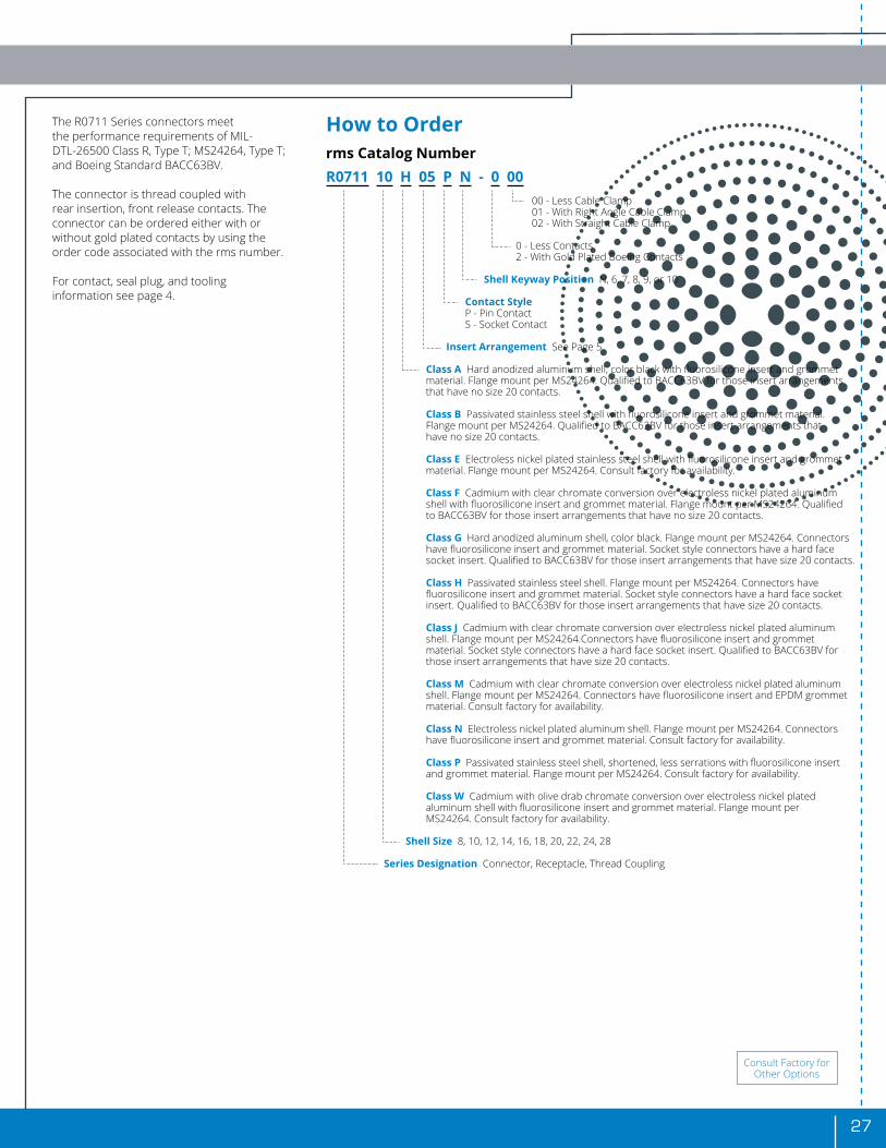
The R0711 Series connectors meet the performance requirements of MIL-DTL-26500 Class R, Type T; MS24264, Type T; and Boeing Standard BACC63BV.
The connector is thread coupled with rear insertion, front release contacts. The connector can be ordered either with or without gold plated contacts by using the order code associated with the rms number.
For contact, seal plug, and tooling information see page 4.
How to Orderrms Catalog NumberR0711 10 H 05 P N - 0 00 00 - Less Cable Clamp 01 - With Right Angle Cable Clamp 02 - With Straight Cable Clamp
0 - Less Contacts 2 - With Gold Plated Boeing Contacts
Shell Keyway Position N, 6, 7, 8, 9, or 10
Contact Style P - Pin Contact S - Socket Contact
Insert Arrangement See Page 5 Class A Hard anodized aluminum shell, color black with fluorosilicone insert and grommet material. Flange mount per MS24264. Qualified to BACC63BV for those insert arrangements that have no size 20 contacts.
Class B Passivated stainless steel shell with fluorosilicone insert and grommet material. Flange mount per MS24264. Qualified to BACC63BV for those insert arrangements that have no size 20 contacts.
Class E Electroless nickel plated stainless steel shell with fluorosilicone insert and grommet material. Flange mount per MS24264. Consult factory for availability.
Class F Cadmium with clear chromate conversion over electroless nickel plated aluminum shell with fluorosilicone insert and grommet material. Flange mount per MS24264. Qualified to BACC63BV for those insert arrangements that have no size 20 contacts.
Class G Hard anodized aluminum shell, color black. Flange mount per MS24264. Connectors have fluorosilicone insert and grommet material. Socket style connectors have a hard face socket insert. Qualified to BACC63BV for those insert arrangements that have size 20 contacts.
Class H Passivated stainless steel shell. Flange mount per MS24264. Connectors have fluorosilicone insert and grommet material. Socket style connectors have a hard face socket insert. Qualified to BACC63BV for those insert arrangements that have size 20 contacts.
Class J Cadmium with clear chromate conversion over electroless nickel plated aluminum shell. Flange mount per MS24264.Connectors have fluorosilicone insert and grommet material. Socket style connectors have a hard face socket insert. Qualified to BACC63BV for those insert arrangements that have size 20 contacts.
Class M Cadmium with clear chromate conversion over electroless nickel plated aluminum shell. Flange mount per MS24264. Connectors have fluorosilicone insert and EPDM grommet material. Consult factory for availability.
Class N Electroless nickel plated aluminum shell. Flange mount per MS24264. Connectors have fluorosilicone insert and grommet material. Consult factory for availability.
Class P Passivated stainless steel shell, shortened, less serrations with fluorosilicone insert and grommet material. Flange mount per MS24264. Consult factory for availability.
Class W Cadmium with olive drab chromate conversion over electroless nickel plated aluminum shell with fluorosilicone insert and grommet material. Flange mount per MS24264. Consult factory for availability.
Shell Size 8, 10, 12, 14, 16, 18, 20, 22, 24, 28
Series Designation Connector, Receptacle, Thread Coupling
Consult Factory for Other Options

28
R0710/R0711 Series
Test Data(Vibration)
About the Power Spectral Density Test Curve and the R0710/R0711 Series
The curve depicted represents a practical compromise between projected accelerated life tests (based on realistic operational aircraft vibration frequencies) and amplitudes elevated to practical test equipment capability levels. This means that “time in test” factor can be adjusted to project operational life expectancy on any application where dynamic data has been established.
rms R0710 and R0711 connector test samples subjected to this test curve showed no evidence of wear or deterioration after vibrating for the hours specified (Total: 16 hours).
Testing
The test specimens were subjected to the random vibration motion specified in the figure on this page. Duration of the vibration was eight (8) hours in each of two mutually perpendicular axis, one of which was the major axis of the connector. A test current of 100ma was applied throughout the duration of the test. The maximum allowable current interruption (discontinuities) was one microsecond.
Acceptance
The connectors remained coupled throughout the test and exhibited no discontinuity greater than one microsecond. Visual examination revealed no wear of the normal mating surface as a result of the vibration (coupling rings, detents, keys, keyways, and bottoming contact surfaces).
Mounting
The plug connector was mated to a corresponding receptacle which was mounted by its normal mounting means to a suitable vibration fixture. The mated pair was wired in a manner that allowed a test current of 100ma in each contact. The resulting wire bundle was then clamped to the test table at a distance of 6 ± 1 inches from the rear of the wire sealing grommet. The connector plug was equipped with a cable clamp.

29
R0712 Series
Bayonet PlugR0712XXXXXXX
Shell Polarity
PolarityFor Connectors
Size 8 and 10For Connectors Size
12, 14, 16, 18, 20, 22, and 24
A B C D A B C D
Normal 105° 140° 215° 265° 105° 140° 215° 265°
6 102° 132° 248° 320° 18° 149° 192° 259°
7 80° 118° 230° 312° 92° 152° 222° 342°
8 35° 140° 205° 275° 84° 152° 204° 334°
9 64° 155° 234° 304° 24° 135° 199° 240°
10* 25° 115° 220° 270° 98° 152° 268° 338°
* Not Available in Size 8 Connector
Shell Size E Dia. Max.
F Dia. Max. G Dia. Max. H
Thread
8 .328 .437 .766 7/16-28 UNEF-2A
10 .420 .562 .906 9/16-24 UNEF-2A
12 .580 .750 1.078 3/4-20 UNEF-2A
14 .664 .812 1.141 13/16-20 UNEF-2A
16 .769 .938 1.266 15/16-20 UNEF-2A
18 .902 1.062 1.375 1 1/16-18 UNEF-2A
20 1.033 1.182 1.510 1 3/16-18 UNEF-2A
22 1.152 1.312 1.625 1 5/16-18 UNEF-2A
24 1.282 1.432 1.760 1 7/16-18 UNEF-2A
DimensionsMaster Key
Not Shown Actual Size
(Continued On Next Page)

30
The R0712 Series connectors meet the performance requirements of MIL-DTL-26500 Class R, Type B; MS24266 Type B; and Boeing standard BACC63BN.
The connector is bayonet coupled with rear insertion, front release contacts. The connector can be ordered either with or without gold plated contacts by using the order code associated with the rms number.
For contact, seal plug, and tooling information see page 4.
How to Orderrms Catalog NumberR0712 10 B 05 P N - 0 00 00 - Less Cable Clamp 01 - With Right Angle Cable Clamp 02 - With Straight Cable Clamp
0 - Less Contacts 2 - With Gold Plated Boeing Contacts
Shell Keyway Position N, 6, 7, 8, 9, or 10
Contact Style P - Pin Contact S - Socket Contact
Insert Arrangement See Page 5 Class A Hard anodized aluminum shell and coupling ring, color black with fluorosilicone insert and grommet material. Qualified to BACC63BN for those insert arrangements that have no size 20 contacts.
Class B Hard anodized aluminum shell and coupling ring, color black. Connectors have fluorosilicone insert and grommet material. Socket style connectors have a hard face socket insert. Qualified to BACC63BN for those insert arrangements that have size 20 contacts.
Class N Electroless nickel plated aluminum shell. Coupling Ring shall be hard anodized, color black with fluorosilicone insert and grommet material. Consult factory for availability.
Shell Size 8, 10, 12, 14, 16, 18, 20, 22, 24
Series Designation Connector, Plug, Bayonet Coupling, Vibration Resistant
Boeing Part Number (Reference)BACC63BN 10 - 5 P N H Blank - With Contacts and Seal Plugs H - Without Contacts and Seal Plugs
Shell Keyway Position N, 6, 7, 8, 9, or 10
Contact Style P - Pin Contact S - Socket Contact
Insert Arrangement See Page 5
“-” - Less Cable Clamp B - Right Angle Cable Clamp C - Straight Cable Clamp Shell Size 8, 10, 12, 14, 16, 18, 20, 22, 24
Series Designation Connector, Electrical, Plug, Straight, Bayonet Coupling, Vibration Resistant
Consult Factory for Other Options
R0712 Series Continued

31
R0708 Series
Flange Mount or Single Hole MountReceptacles
Shell Polarity
PolarityFor Connectors
Size 8 and 10For Connectors Size
12, 14, 16, 18, 20, 22 and 24
A B C D A B C D
Normal 105˚ 140˚ 215˚ 265˚ 105˚ 140˚ 215˚ 265˚
6 102˚ 132˚ 248˚ 320˚ 18˚ 149˚ 192˚ 259˚
7 80˚ 118˚ 230˚ 312˚ 92˚ 152˚ 222˚ 342˚
8 35˚ 140˚ 205˚ 275˚ 84˚ 152˚ 204˚ 334˚
9 64˚ 155˚ 234˚ 304˚ 24˚ 135˚ 199˚ 240˚
10* 25˚ 115˚ 220˚ 270˚ 98˚ 152˚ 268˚ 338˚
* Not Available in Size 8 Connector
Shell Size
E ± .005
F ± .005
G Dia. /1 + .000 – .009
J Dia. Max.
K Dia. Max.
M Dia. Min .
N Dia. Min .
8 .812 .594 .125 .500 .561 .620 .510
10 .937 .719 .125 .620 .696 .748 .635
12 1.031 .812 .125 .750 .875 .913 .750
14 1.125 .906 .125 .871 .935 .980 .885
16 1.250 .969 .125 .996 1.062 1.107 1.010
18 1.343 1.062 .125 1.062 1.187 1.209 1.072
20 1.437 1.156 .125 1.184 1.312 1.337 1.192
22 1.562 1.250 .125 1.312 1.437 1.452 1.322
24 1.703 1.375 .154 1.432 1.562 1.577 1.442
1/ Unless Specified Otherwise by Part Number Configuration
The R0708 Series connectors are designed for termination to printed circuit boards, flex circuitry, or may be furnished with wire wrap or solder pot contacts.
The mating interface is compatible with MIL-DTL-26500 and MIL-DTL-83723/86, /87, /91, /92, /95 & /96 Type T Connectors. There are several mounting Flange variations as well as contact termination lengths as shown in the following figures. Consult factory for availability.
Not Shown Actual Size
Panel Mounting for Standard FlangeHole Cut-out
DimensionsMaster Key
(Continued On Next Page)

32
Flange Mount or Single Hole MountReceptacles
Not Shown Actual Size
How to Orderrms Catalog NumberR0708 10 A 05 P N A 1 1 - A Special Option Code (Only Marked if Applicable) Termination Pin Length Solder Pin (Flange Option 1) 1 - .260 ± .015 2 - .366 ± .020 Mounting Flange Variation 1 - Square Flange Mount, Standard Thru Holes (4). 2 - Square Flange Mount, Chamfered Thru Holes (4). Contact Type A - Solder Pin for Use with Printed Circuit Boards or Flex Circuitry, Step Pin with .030 X .060 Long B - Solder Cup D - Solder Pin for Use with Printed Circuit Boards or Flex Circuitry, .030 Contact Tail E - Solder Pin for Use with Printed Circuit Boards or Flex Circuitry, .024 Contact Tail with Solder Coat F - Solder Pin for Use with Printed Circuit Boards or Flex Circuitry, .030 Contact Tail with Solder Coat G - Solder Pin for Use with Printed Circuit Boards or Flex Circuitry, .019 Contact Tail with Solder Coat Shell Keyway Position N, 6, 7, 8, 9 or 10 Contact Style “P” - Pin Contact, “S” - Socket Contact Insert Arrangement See Page 5 Shell Finish A - Hard Anodized Aluminum Shell B - Stainless Steel Shell, Passivated G - Cadmium over Nickel Plated Aluminum Shell with Clear Chromate Conversion H - Cadmium over Nickel Plated Aluminum Shell with Olive Drab Chromate Conversion with Resilient Contact Potting N - Nickel Plated Aluminum Shell W - Cadmium over Nickel Plated Aluminum Shell with Olive Drab Chromate Conversion Z - Cadmium over Nickel Plated Aluminum Shell with Clear Chromate Conversion without Dry Film Lubricant on Mating Thread Shell Size 08, 10, 12, 14, 16, 18, 20, 22, 24 Series Designation Connector, Receptacle, Non-Removable Contact
– Consult Factory for Other Options –
(Continued On Next Page)
R0708 Series Continued

33
Flange Mount Threaded Fasteners Pressed in PlaceReceptacles
Threaded Fastener .112-40UNJC-3B (4)
Not Shown Actual Size
How to Orderrms Catalog NumberR0708 10 A 05 P N A 7 1 - A Special Option Code (Only Marked if Applicable) Termination Pin Length Solder Pin (Flange Option 7) 1 - .366 ± .015 Mounting Flange Variation 7 - Square Flange Mount, Threaded Fasteners Pressed in Place (4) Contact Type A - Solder Pin for Use with Printed Circuit Boards or Flex Circuitry, Step Pin with .030 X .060 Long B - Solder Cup D - Solder Pin for Use with Printed Circuit Boards or Flex Circuitry, .030 Contact Tail E - Solder Pin for Use with Printed Circuit Boards or Flex Circuitry, .024 Contact Tail with Solder Coat F - Solder Pin for Use with Printed Circuit Boards or Flex Circuitry, .030 Contact Tail with Solder Coat G - Solder Pin for Use with Printed Circuit Boards or Flex Circuitry, .019 Contact Tail with Solder Coat Shell Keyway Position N, 6, 7, 8, 9 or 10 Contact Style “P” - Pin Contact, “S” - Socket Contact Insert Arrangement See Page 5 Shell Finish A - Hard Anodized Aluminum Shell B - Stainless Steel Shell, Passivated G - Cadmium over Nickel Plated Aluminum Shell with Clear Chromate Conversion H - Cadmium over Nickel Plated Aluminum Shell with Olive Drab Chromate Conversion with Resilient Contact Potting N - Nickel Plated Aluminum Shell W - Cadmium over Nickel Plated Aluminum Shell with Olive Drab Chromate Conversion Z - Cadmium over Nickel Plated Aluminum Shell with Clear Chromate Conversion without Dry Film Lubricant on Mating Thread Shell Size 08, 10, 12, 14, 16, 18, 20, 22, 24 Series Designation Connector, Receptacle, Non-Removable Contact
– Consult Factory for Other Options –

34
R0709 Series
Flange Mount or Single Hole MountReceptacles
Shell Polarity
PolarityFor Connectors
Size 8 and 10For Connectors Size
12, 14, 16, 18, 20, 22 and 24
A B C D A B C D
Normal 105˚ 140˚ 215˚ 265˚ 105˚ 140˚ 215˚ 265˚
6 102˚ 132˚ 248˚ 320˚ 18˚ 149˚ 192˚ 259˚
7 80˚ 118˚ 230˚ 312˚ 92˚ 152˚ 222˚ 342˚
8 35˚ 140˚ 205˚ 275˚ 84˚ 152˚ 204˚ 334˚
9 64˚ 155˚ 234˚ 304˚ 24˚ 135˚ 199˚ 240˚
10* 25˚ 115˚ 220˚ 270˚ 98˚ 152˚ 268˚ 338˚
* Not Available in Size 8 Connector
Shell Size
E ± .005
F ± .005
G Dia. /1 + .000 – .009
J Dia. Max.
K Dia. Max.
M Dia. Min .
N Dia. Min .
8 .812 .594 .125 .500 .561 .620 .510
10 .937 .719 .125 .620 .696 .748 .635
12 1.031 .812 .125 .750 .875 .913 .750
14 1.125 .906 .125 .871 .935 .980 .885
16 1.250 .969 .125 .996 1.062 1.107 1.010
18 1.343 1.062 .125 1.062 1.187 1.209 1.072
20 1.437 1.156 .125 1.184 1.312 1.337 1.192
22 1.562 1.250 .125 1.312 1.437 1.452 1.322
24 1.703 1.375 .154 1.432 1.562 1.577 1.442
1/ Unless Specified Otherwise by Part Number Configuration
DimensionsMaster Key
Panel Mounting for Standard FlangeHole Cut-out
The R0709 Series connectors are designed for termination to printed circuit boards, flex circuitry, or may be furnished with solder pin, wire wrap, compliant contact or solder pot contacts.
The gold plated contacts are designed for ease of maintenance with insertion and removal accomplished through the front side of the connector eliminating the requirement to disassemble the entire connector from its mounting. The mating interface is compatible with MIL-DTL-26500 and MIL-DTL-83723/75, /76, /77, and /78 Type B Connectors. There are several mounting Flange variations as well as contact termination lengths as shown in the following figures. Consult factory for availability.
Not Shown Actual Size

35(Continued On Next Page)
Flange Mount or Single Hole MountReceptacles
Not Shown Actual Size
How to Orderrms Catalog NumberR0709 10 A 05 P N A 1 1 Termination Pin Length Solder Pin (Type A & D) Wire Wrap (B) Compliant Pin (0) Flange Options 1,2,5,6) (Flange Option 1) (Flange Option 0) 1-.255 ± .020 1 - .750 ± .020 1 - .323 ± .020 2-.935 ± .020 3-.526 ± .020 4-.365 ± .020 5-.965 ± .020 6-.396 ± .020 7-.436 ± .020 8-.978 ± .020 (No Solder Coat) 9-.557 ± .020 Mounting Flange Variation 0 - Square Flange Mount, Standard Thru Holes (4) 1 - Square Flange Mount, Standard Thru Holes (4) 2 - Square Flange Mount, Chamfered Thru Holes (4) 5 - Square Flange Mount, Standard Thru Holes (4), Flange Flush to Rear of Shell 6 - Square Flange Mount, ( .142)Thru Holes (4) Contact Type A - Solder Pin Termination B - Wire Wrap Termination C - Compliant Pin Termination with Solder Post D - Solder Pin Termination - No Solder Coat 0 - Compliant Pin Termination with Solder Post Shell Keyway Position N, 6, 7, 8, 9 or 10 Contact Style “P” - Pin Contact, “S” - Socket Contact Insert Arrangement See Page 5 Shell Finish A - Hard Anodized Aluminum Shell G - Cadmium over Nickel Plated Aluminum Shell with Clear Chromate Conversion N - Nickel Plated Aluminum Shell W - Cadmium over Nickel Plated Aluminum Shell with Olive Drab Chromate Conversion Shell Size 08, 10, 12, 14, 16, 18, 20, 22, 24 Series Designation “Connector, Receptacle, Flange Mount, Front Insert, Front Removable Contacts”
– Consult Factory for Other Options –

36
How to Orderrms Catalog NumberR0709 10 A 05 P N A 4 1 Termination Pin Length Solder Pin (A) Solder Pin (A) Compliant Pin (C) (Flange Options 4,7,8,9 and J) (Flange Option L) (Flange Option M) 1 -.255 ± .020 6 - .524 ± .020 1 - .241 ± .020 2 -.365 ± .020 3 -.526 ± .020 Solder Pin (A) Compliant Pin (C) 4 -.935 ± .020 (Flange Option N) (Flange Option N) 5 -.297 ± .020 1 - .217 ± .020 1 - .235 ± .020 6 -.524 ± .020 Solder Pin (D) (Flange Option J) 5 - .297 ± .020 Mounting Flange Variation 4 - Square Flange Mount, (.157 ± .005) Board Mounting Standoffs, .086-56UNC-2B Threaded Inserts in Mounting Holes (4) 7 - Square Flange Mount, (.225 ± .005) Board Mounting Standoffs, Threaded Inserts in Mounting Holes (4) 8 - Square Flange Mount, (.335 ± .005) Board Mounting Standoffs, Threaded Inserts in Mounting Holes (4) 9 - Square Flange Mount, (.200 ± .005) Board Mounting Standoffs, Threaded Inserts in Mounting Holes (4) J- Square Flange Mount, (.200 ± .005) Board Mounting Standoffs, .112-40UNC-2B Threaded Inserts in Mounting Holes (4) L - Square Flange Mount, (.500 ± .005) Board Mounting Standoffs, Threaded Inserts in Mounting Holes (4) M - Square Flange Mount, (.125 ± .005) Board Mounting Standoffs with Rear Flange Alignment Pin, Chamfered Thru Holes (4) N - Square Flange Mount, (.200 ± .005) Board Mounting Standoffs with Rear Flange Alignment Pin, .112-40UNC-2B Threaded Inserts in Mounting Holes (4) Contact Type A - Solder Pin Termination B - Wire Wrap Termination C - Compliant Pin Termination with Solder Post D - Solder Pin Termination - No Solder Coat 0 - Compliant Pin Termination with Solder Post Shell Keyway Position N, 6, 7, 8, 9 or 10 Contact Style “P” - Pin Contact, “S” - Socket Contact Insert Arrangement See Page 5 Shell Finish A - Hard Anodized Aluminum Shell G - Cadmium over Nickel Plated Aluminum Shell with Clear Chromate Conversion N - Nickel Plated Aluminum Shell W - Cadmium over Nickel Plated Aluminum Shell with Olive Drab Chromate Conversion Shell Size 08, 10, 12, 14, 16, 18, 20, 22, 24 Series Designation “Connector, Receptacle, Flange Mount, Front Insert, Front Removable Contacts”
– Consult Factory for Other Options –
Flange Mount Board Mounting StandoffsReceptacles
Not Shown Actual Size
Standoff with Threaded Insert (4)
Shell Size Thread Size
8 - 14 .086-56UNC-2B
16 - 24 .112-40UNC-2B
Unless Otherwise Specified in Table
R0709 Series Continued

37
Single Hole Mount Board Mounting StandoffsReceptacles
Not Shown Actual Size
How to Orderrms Catalog NumberR0709 10 A 05 P N A H 1 Termination Pin Length Solder Pin (A) Compliant Pin (C) (Flange Option E, H and K) (Flange Option H) 1 - .159 + .020 1 - .190 ± .020
Compliant Pin (C) Solder Pin (D) (Flange Option K) (Flange Option K) 1 - .173 ± .020 1 - .159 + .020 Mounting Flange Variation E - Square Flange, Single Hole Mount (.150 ± .005) Board Mounting Standoffs, (2) .112-40UNC-2B Threaded Inserts in Mounting Holes, (2) Thru Holes H - Square Flange, Single Hole Mount (.150 ± .005) Board Mounting Standoffs, (2) .112-40UNC-2B Threaded Inserts in Mounting Holes, (2) Thru Holes. Less Grounding Washer, Friction Washer, and Hexagon Nut K - Square Flange, Single Hole Mount - Less Thread (.200 ± .005) Board Mounting Standoffs, .112-40UNC-2B Threaded Inserts in Mounting Holes (4). Less Grounding Washer, Friction Washer and Hexagon Nut Contact Type A - Solder Pin Termination B - Wire Wrap Termination C - Compliant Pin Termination with Solder Post D - Solder Pin Termination - No Solder Coat 0 - Compliant Pin Termination with Solder Post Shell Keyway Position N, 6, 7, 8, 9 or 10 Contact Style “P” - Pin Contact, “S” - Socket Contact Insert Arrangement See Page 5 Shell Finish A - Hard Anodized Aluminum Shell G - Cadmium over Nickel Plated Aluminum Shell with Clear Chromate Conversion N - Nickel Plated Aluminum Shell W - Cadmium over Nickel Plated Aluminum Shell with Olive Drab Chromate Conversion Shell Size 08, 10, 12, 14, 16, 18, 20, 22, 24 Series Designation “Connector, Receptacle, Flange Mount, Front Insert, Front Removable Contacts”
– Consult Factory for Other Options –

38
R0713 Series
The R0713 Series connectors are designed for termination to printed circuit boards, flex circuitry, or may be furnished with wire wrap or solder pot contacts.
The mating interface is compatible with MIL-DTL-26500 and MIL-DTL-83723/75, /76, /77, & /78 Type B Connectors. There are several mounting Flange variations as well as contact termination lengths as shown in the following figures. Consult factory for availability.
Flange Mount or Single Hole MountReceptacles
Shell Polarity
PolarityFor Connectors Size 8 and 10 For Connectors Size
12, 14, 16, 18, 20, 22 and 24
A B C D A B C D
Normal 105˚ 140˚ 215˚ 265˚ 105˚ 140˚ 215˚ 265˚
6 102˚ 132˚ 248˚ 320˚ 18˚ 149˚ 192˚ 259˚
7 80˚ 118˚ 230˚ 312˚ 92˚ 152˚ 222˚ 342˚
8 35˚ 140˚ 205˚ 275˚ 84˚ 152˚ 204˚ 334˚
9 64˚ 155˚ 234˚ 304˚ 24˚ 135˚ 199˚ 240˚
10* 25˚ 115˚ 220˚ 270˚ 98˚ 152˚ 268˚ 338˚
* Not Available in Size 8 Connector
Shell Size
E ± .005
F ± .005
G Dia. 1/ + .000 - .009
J Dia. Max.
K Dia. Max.
M Dia. Min .
N Dia. Min .
8 .812 .594 .125 .500 .561 .620 .510
10 .937 .719 .125 .620 .696 .748 .635
12 1.031 .812 .125 .750 .875 .913 .750
14 1.125 .906 .125 .871 .935 .980 .885
16 1.250 .969 .125 .996 1.062 1.107 1.010
18 1.343 1.062 .125 1.062 1.187 1.209 1.072
20 1.437 1.156 .125 1.184 1.312 1.337 1.192
22 1.562 1.250 .125 1.312 1.437 1.452 1.322
24 1.703 1.375 .154 1.432 1.562 1.577 1.442
1/ Unless Specified Otherwise by Part Number Configuration
Panel MountingHole Cut-out
Not Shown Actual Size

39
Flange Mount or Single Hole MountReceptacles
How to Orderrms Catalog NumberR0713 10 A 05 P N A 1 1 - A Special Option Code (Only Marked if Applicable) Termination Pin Length Solder Pin (Type A & D) Solder Cup (Type B) Wire Wrap (Type C) 1 - .205 ± .020 1 - .185 ± .020 1 - .270 ± .020 2 - .255 ± .020 2 - .815 ± .020 3 - .575 ± .020 4 - .935 ± .020 Solder Pin (Type E) Solder Pin (Type F) 5 - .505 ± .020 2 - .260 ± .020 1 - .159 ± .020 6 - .390 ± .020 2 - .225 ± .020 7 - .100 ± .010 8 - .300 ± .020 9 - .735 ± .020 Mounting Flange Variation 1 - Square Flange Mount, Standard Thru Holes (4). 2 - Square Flange Mount, Chamfered Thru Holes (4). 3 - Single Hole Mount with Jam Nut - Consult Factory. 5 - Square Flange Mount, Standard Thru Holes (4). Flange Flush to Rear of Shell - Consult Factory. 6 - Square Flange Mount, ( .142) Thru Holes (4). 8 - Flange Mount with External Key - Consult Factory H - Square Flange, Single Hole Mount, (2) Threaded Mounting Holes, (2) Thru Holes. (.150 + .005 Standoffs) - Consult Factory. Contact Type A - Solder Pin for Use with Printed Circuit Boards or Flex Circuitry B - Solder Cup C - Wire Wrap Square Tail D - Solder Pin for Use with Printed Circuit Boards or Flex Circuitry E - Solder Pin for Use with Printed Circuit Boards or Flex Circuitry, Step Pin with .030 x .060 Long F - Solder Pin (Size 12 Contacts Only) for Use with Printed Circuit Boards or Flex Circuitry with Solder Coat G - Solder Pin for Use with Printed Circuit Boards or Flex Circuitry with Special Contact Placement - Consult Factory H - Solder Pin for Use with Printed Circuit Boards or Flex Circuitry less Solder Coat K - Solder Pin for Use with Printed Circuit Boards or Flex Circuitry with Solder Coat Shell Keyway Position N, 6, 7, 8, 9 or 10 Contact Style “P” - Pin Contact, “S” - Socket Contact Insert Arrangement See Page 5 Shell Finish A - Hard Anodized Aluminum Shell F - Cadmium over Nickel Plated Aluminum Shell with Clear Chromate Conversion with Resilient Contact Potting G - Cadmium over Nickel Plated Aluminum Shell with Clear Chromate Conversion H - Cadmium over Nickel Plated Aluminum Shell with Olive Drab Chromate Conversion with Resilient Contact Potting N - Nickel Plated Aluminum Shell W - Cadmium over Nickel Plated Aluminum Shell with Olive Drab Chromate Conversion Shell Size 08, 10, 12, 14, 16, 18, 20, 22, 24 Series Designation Connector, Receptacle, Non-Removable Contact
– Consult Factory for Other Options –
Not Shown Actual Size
(Continued On Next Page)

40
Flange Mount Threaded Mounting HolesReceptacles
How to Orderrms Catalog NumberR0713 10 A 05 P N A 4 1 - A Special Option Code (Only Marked if Applicable) Termination Pin Length (Determined by Stand-Off Height - Consult Factory) Mounting Flange Variation 4 - Square Flange Mount, Threaded Mounting Holes (4). (Standard Height = .157” STD, Consult Factory for Other Options) K - Square Flange Mount, Threaded Mounting Holes (4). (.200 + .005 Standoffs) with Rear Flange Alignment Pins Contact Type A - Solder Pin for Use with Printed Circuit Boards or Flex Circuitry B - Solder Cup H - Solder Pin for Use with Printed Circuit Boards or Flex Circuitry Shell Keyway Position N, 6, 7, 8, 9 or 10 Contact Style “P” - Pin Contact, “S” - Socket Contact Insert Arrangement See Page 5 Shell Finish A - Hard Anodized Aluminum Shell F - Cadmium over Nickel Plated Aluminum Shell with Clear Chromate Conversion with Resilient Contact Potting G - Cadmium over Nickel Plated Aluminum Shell with Clear Chromate Conversion H - Cadmium over Nickel Plated Aluminum Shell with Olive Drab Chromate Conversion with Resilient Contact Potting N - Nickel Plated Aluminum Shell W - Cadmium over Nickel Plated Aluminum Shell with Olive Drab Chromate Conversion Shell Size 08, 10, 12, 14, 16, 18, 20, 22, 24 Series Designation Connector, Receptacle, Non-Removable Contact
– Consult Factory for Other Options –
Not Shown Actual Size
Stand-off with Threaded Insert (4)
Shell Size Thread Size
8 - 14 .086-56UNC-2B
16 - 24 .112-40UNC-2B
Unless Otherwise Specified in Table
R0713 Series Continued

41
Flange Mount Threaded Fasteners Pressed in PlaceReceptacles
How to Orderrms Catalog NumberR0713 10 A 05 P N A 7 1 - A Special Option Code (Only Marked if Applicable) Termination Pin Length 1 - .205 ± .020 2 - .255 ± .020 3 - .575 ± .020 4 - .935 ± .020 5 - .505 ± .020 6 - .390 ± .020 7 - .100 ± .010 8 - .300 ± .020 9 - .735 ± .020 Mounting Flange Variation 7 - Square Flange Mount, Threaded Fasteners Pressed in Place (4). Contact Type A & D - Solder Pin for Use with Printed Circuit Boards or Flex Circuitry K - Solder Pin for Use with Printed Circuit Boards or Flex Circuitry with Solder Coat Shell Keyway Position N, 6, 7, 8, 9 or 10 Contact Style “P” - Pin Contact, “S” - Socket Contact Insert Arrangement See Page 5 Shell Finish A - Hard Anodized Aluminum Shell F - Cadmium over Nickel Plated Aluminum Shell with Clear Chromate Conversion with Resilient Contact Potting G - Cadmium over Nickel Plated Aluminum Shell with Clear Chromate Conversion H - Cadmium over Nickel Plated Aluminum Shell with Olive Drab Chromate Conversion with Resilient Contact Potting N - Nickel Plated Aluminum Shell W - Cadmium over Nickel Plated Aluminum Shell with Olive Drab Chromate Conversion Shell Size 08, 10, 12, 14, 16, 18, 20, 22, 24 Series Designation Connector, Receptacle, Non-Removable Contact
– Consult Factory for Other Options –
Threaded Fastener.112-40UNJC-3B (4)
Not Shown Actual Size

42
Flange Mount Receptacles
The R0714 Series connectors are designed for termination to printed circuit boards, flex circuitry, or may be furnished with solder pin contacts.
The gold plated contacts are designed for ease of maintenance with insertion and removal accomplished through the front side of the connector eliminating the requirement to disassemble the entire connector from its mounting. The mating interface is compatible with MIL-DTL-26500 and MIL-DTL-83723/75, /76, /77, & /78 Type B Connectors. There are several mounting Flange variations as well as contact termination lengths as shown in the following figures. Consult factory for availability.
Shell Polarity
PolarityFor Connectors Size 8 and 10 For Connectors Size
12, 14, 16, 18, 20, 22 and 24
A B C D A B C D
Normal 105˚ 140˚ 215˚ 265˚ 105˚ 140˚ 215˚ 265˚
6 102˚ 132˚ 248˚ 320˚ 18˚ 149˚ 192˚ 259˚
7 80˚ 118˚ 230˚ 312˚ 92˚ 152˚ 222˚ 342˚
8 35˚ 140˚ 205˚ 275˚ 84˚ 152˚ 204˚ 334˚
9 64˚ 155˚ 234˚ 304˚ 24˚ 135˚ 199˚ 240˚
10* 25˚ 115˚ 220˚ 270˚ 98˚ 152˚ 268˚ 338˚
* Not Available in Size 8 Connector
Shell Size E ± .005
F ± .005
G Dia. 1/ + .000 - .009
K Dia. Max.
M Dia. Min .
N Dia. Min .
8 .812 .594 .125 .561 .620 .510
10 .937 .719 .125 .696 .748 .635
12 1.031 .812 .125 .875 .913 .750
14 1.125 .906 .125 .935 .980 .885
16 1.250 .969 .125 1.062 1.107 1.010
18 1.343 1.062 .125 1.187 1.209 1.072
20 1.437 1.156 .125 1.312 1.337 1.192
22 1.562 1.250 .125 1.437 1.452 1.322
24 1.703 1.375 .154 1.562 1.577 1.442
1/ Unless Specified Otherwise by Part Number Configuration
DimensionsMaster Key
Panel Mounting for Standard FlangeHole Cut-out
Not Shown Actual Size
R0714 Series

43
Flange Mount Receptacles
How to Orderrms Catalog NumberR0714 10 A 05 P N A 3 1 - A Special Option Code (Only Marked if Applicable) Termination Pin Length 1 - .125 ± .020 Mounting Flange Variation 1 - Single Hole Mount with Jam Nut - Consult Factory 3 - Square Flange Mount, Standard Thru Holes Contact Type A - Solder Pin Termination for Use with Printed Circuit Boards or Flex Circuitry - No Solder Coat B - Solder Pin Termination for Use with Printed Circuit Boards or Flex Circuitry - with Solder Coat Shell Keyway Position N, 6, 7, 8, 9 or 10 Contact Style “P” - Pin Contact, “S” - Socket Contact Insert Arrangement See Page 5 Shell Finish A - Hard Anodized Aluminum Shell B - Hard Anodized Aluminum Shell with Mounting Tabs, Chemical Film Coated G - Cadmium over Nickel Plated Aluminum Shell with Clear Chromate Conversion N - Nickel Plated Aluminum Shell W - Cadmium over Nickel Plated Aluminum Shell with Olive Drab Chromate Conversion Shell Size 08, 10, 12, 14, 16, 18, 20, 22, 24 Series Designation Connector, Receptacle, Non-Removable Contact
– Consult Factory for Other Options –
.112-40UNC-2B (2)
Not Shown Actual Size

44
R0715 Series
Square FlangeBayonet or Threaded ReceptacleReceptacles
Shell Polarity
PolarityFor Connectors Size 8 and 10 For Connectors Size
12, 14, 16, 18, 20, 22, and 24
A B C D A B C D
Normal 105° 140° 215° 265° 105° 140° 215° 265°
6 102° 132° 248° 320° 18° 149° 192° 259°
7 80° 118° 230° 312° 92° 152° 222° 342°
8 35° 140° 205° 275° 84° 152° 204° 334°
9 64° 155° 234° 304° 24° 135° 199° 240°
10* 25° 115° 220° 270° 98° 152° 268° 338°
* Not available in size 8 connector
Shell Size
E ± .005
F ± .005
G Dia. + .000 - .009
H Dia. Max.
J Dia. + .003 - .000
K Thread
L Dia
Min .
M Dia. Min .
8 .812 .594 .125 .561 .495 9/16-24 UNEF-2A .510 .620
10 .937 .719 .125 .696 .620 11/16-24 UNEF-2A .635 .748
12 1.031 .812 .125 .875 .743 7/8-20 UNEF-2A .750 .913
14 1.125 .906 .125 .935 .869 15/16-20 UNEF-2A .885 .980
16 1.250 .969 .125 1.062 .993 1 1/16-18 UNEF-2A 1.010 1.107
18 1.343 1.062 .125 1.187 1.056 1 3/16-18 UNEF-2A 1.072 1.209
20 1.437 1.156 .125 1.312 1.182 1 5/16-18 UNEF-2A 1.192 1.337
22 1.562 1.250 .125 1.437 1.305 1 7/16-18 UNEF-2A 1.322 1.452
24 1.703 1.375 .154 1.562 1.430 1 9/16-18 UNEF-2A 1.442 1.577
Not Shown Actual Size
DimensionsMaster Key

45
Square FlangeBayonet or Threaded ReceptacleReceptacles
How to Orderrms Catalog NumberR0715 10 A B C 05 P N - 0 0 - Less Contacts 2 - With Gold Plated Contacts Shell Keyway Position N, 6, 7, 8, 9, or 10 Contact Style P - Pin Contact S - Socket Contact Insert Arrangement See Page 5 Mounting Flange Thickness C - .069 ± .003 D - .100 ± .005 Coupling Style B - Bayonet Coupling T - Threaded Coupling Class A Hard anodized aluminum shell, color black. Class G Cadmium with clear chromate conversion over electroless nickel plated aluminum shell. Class N Electroless nickel plated aluminum shell. Class W Cadmium with olive drab chromate conversion over electroless nickel plated aluminum shell. Class S Passivated stainless steel shell. Shell Size 8, 10, 12, 14, 16, 18, 20, 22, 24 Series Designation Connector, Receptacle, Special Flange Mount
Consult Factory for Other Options
The R0715 Series connectors are used in areas where space within an electrical box or device is limited. The flange has been moved to the rear. There are no provisions for rear accessory hardware.
The connectors meet the performance requirements of MIL-DTL-26500 Type B or T, Class R. They are designed to mate with standard MIL-DTL-26500 connectors or derivatives of MIL-DTL-26500.
Panel MountingHole Cut-out

46
R0726 Series
Threaded Plug Self-lockingR0726XXXXXXX
Shell Polarity
PolarityFor Connectors Size 8 and 10 For Connectors Size
12, 14, 16, 18, 20, 22, 24 and 28
A B C D A B C D
Normal 105° 140° 215° 265° 105° 140° 215° 265°
6 102° 132° 248° 320° 18° 149° 192° 259°
7 80° 118° 230° 312° 92° 152° 222° 342°
8 35° 140° 205° 275° 84° 152° 204° 334°
9 64° 155° 234° 304° 24° 135° 199° 240°
10* 25° 115° 220° 270° 98° 152° 268° 338°
* Not available in size 8 connector
Shell Size
E Dia. Max.
F Dia. Max.
G Dia. Max. H ThreadClass A, C, W Class B
8 .311 .500 .837 .821 1/2-20UNF-2A
10 .376 .625 .972 .972 5/8-24UNEF-2A
12 .552 .750 1.080 1.080 3/4-20UNEF-2A
14 .618 .875 1.230 1.230 7/8-20UNEF-2A
16 .763 1.000 1.355 1.355 1-20UNEF-2A
18 .870 1.062 1.470 1.470 1 1/16-18UNEF-2A
20 .991 1.187 1.067 1.607 1 3/16-18UNEF-2A
22 1.111 1.312 1.735 1.735 1 5/16-18UNEF-2A
24 1.240 1.437 1.858 1.858 1 7/16-18UNEF-2A
28 1.490 1.748 2.113 2.113 1 3/4-18UNS-2A
Not Shown Actual Size
DimensionsMaster Key

47
How to Orderrms Catalog NumberR0726 10 A 05 P N - 0 00 00 - Less Cable Clamp 01 - With Right Angle Cable Clamp 02 - With Straight Cable Clamp
0 - Less Contacts 2 - With Gold Plated Contacts
Shell Keyway Position N, 6, 7, 8, 9, or 10
Contact Style P - Pin Contact S - Socket Contact
Insert Arrangement See Page 5 Class A Hard anodized aluminum shell and coupling ring, color black. Connectors have fluorosilicone insert and EPDM grommet material. Socket style connectors have a hard face socket insert. Qualified to BACC63DY. Temperature exposure shall be 125° C maximum.
Class B Passivated stainless steel shell and coupling ring. The shell has a ground spring. Connectors have fluorosilicone insert and EPDM grommet material. Socket style connectors have a hard face socket insert. Qualified to BACC63DY. Temperature exposure shall be 125° C maximum.
Class C Cadmium with clear chromate conversion over electroless nickel plated aluminum shell. The shell has a ground spring. The coupling ring shall be hard anodized, color black. Connectors have fluorosilicone insert and EPDM grommet material. Socket style connectors have a hard face socket insert. Qualified to BACC63DY. Temperature exposure shall be 125° C maximum.
Class W Cadmium with olive drab chromate conversion over electroless nickel plated aluminum shell. The shell has a ground spring. The coupling ring shall be hard anodized, color black. Connectors have fluorosilicone insert and EPDM grommet material. Socket style connectors have a hard face socket insert. Temperature exposure shall be 125° C maximum.
Shell Size 8, 10, 12, 14, 16, 18, 20, 22, 24, 28
Series Designation Connector, Plug, Threaded Coupling, Self-locking, Vibration and Skydrol Resistant
Boeing Part Number (Reference)BACC63DY 10 A 5 P N H Blank - With Contacts and Seal Plugs H - Without Contacts and Seal Plugs
Shell Keyway Position N, 6, 7, 8, 9, or 10
Contact Style P - Pin Contact S - Socket Contact
Insert Arrangement See Page 5
A - Anodized aluminum with rear accessory teeth per MS3155 B - Stainless steel with rear accessory teeth per MS3155 and grounding spring C - Cadmium plated aluminum with rear accessory teeth per MS3155 and grounding spring
Shell Size 8, 10, 12, 14, 16, 18, 20, 22, 24, 28
Series Designation Plug, Threaded Coupling, Self-locking, Vibration and Skydrol Resistant
Consult Factory for Other Options
The R0726 Series connectors meet the performance requirements of MIL-DTL-2650 Class R, Type T; MS24266 Type T; and Boeing Standard BACC63DY.
The connector is thread coupled with rear insertion, front release contacts. The connector can be ordered either with or without gold plated contacts by using the order code associated with the rms number.
For contact, seal plug, and tooling information see page 4.
Threaded Plug Self-lockingR0726XXXXXXX

48
R0727 Series
Threaded ReceptacleR0727XXXXXXX
Shell Polarity
PolarityFor Connectors Size 8 and 10 For Connectors Size
12, 14, 16, 18, 20, 22, 24 and 28
A B C D A B C D
Normal 105° 140° 215° 265° 105° 140° 215° 265°
6 102° 132° 248° 320° 18° 149° 192° 259°
7 80° 118° 230° 312° 92° 152° 222° 342°
8 35° 140° 205° 275° 84° 152° 204° 334°
9 64° 155° 234° 304° 24° 135° 199° 240°
10* 25° 115° 220° 270° 98° 152° 268° 338°
* Not available in size 8 connector
Shell Size
E ± .005
F ± .005
G Dia. + .000 - .009
H Dia. Max.
J Dia. Max.
K Dia. Max.
L Thread
M Dia. Min .
N Dia. Min .
P Thread
8 .812 .594 .125 .311 .500 .561 1/2-20UNF-2A .620 .510 9/16-24UNEF-2A
10 .937 .719 .125 .376 .625 .696 5/8-24UNEF-2A .748 .635 11/16-24UNEF-2A
12 1.031 .812 .125 .552 .750 .875 3/4-20UNEF-2A .913 .760 7/8-20UNEF-2A
14 1.125 .906 .125 .618 .875 .935 7/8-20UNEF-2A .980 .885 15/16-20UNEF-2A
16 1.250 .969 .125 .763 1.000 1.062 1-20UNEF-2A 1.107 1.010 1 1/16-18UNEF-2A
18 1.343 1.062 .125 .870 1.062 1.187 1 1/16-18UNEF-2A 1.209 1.072 1 3/16-18UNEF-2A
20 1.437 1.156 .125 .991 1.187 1.312 1 3/16-18UNEF-2A 1.337 1.192 1 5/16-18UNEF-2A
22 1.562 1.250 .125 1.111 1.312 1.437 1 5/16-18UNEF-2A 1.452 1.322 1 7/16-18UNEF-2A
24 1.703 1.375 .154 1.240 1.437 1.562 1 7/16-18UNEF-2A 1.577 1.442 1 9/16-18UNEF-2A
28 2.000 1.562 .154 1.490 1.750 1.812 1 3/4-18UNS-2A 1.827 1.760 1 13/16-16UN-2A
Not Shown Actual Size
Panel MountingHole Cut-out
DimensionsMaster Key

4949
How to Orderrms Catalog NumberR0727 10 A 05 P N - 0 00 00 - Less Cable Clamp 01 - With Right Angle Cable Clamp 02 - With Straight Cable Clamp
0 - Less Contacts 2 - With Gold Plated Contacts
Shell Keyway Position N, 6, 7, 8, 9, or 10
Contact Style P - Pin Contact S - Socket Contact
Insert Arrangement See Page 5 Class A Hard anodized aluminum shell, color black. Flange mount per MS24264. Connectors have fluorosilicone insert and EPDM grommet material. Socket style connectors have a hard face socket insert. Qualified to BACC63BVDW. Temperature exposure shall be 125° C maximum.
Class B Passivated stainless steel shell. Flange mount per MS24264. Connectors have fluorosilicone insert and EPDM grommet material. Socket style connectors have a hard face socket insert. Qualified to BACC63DW. Temperature exposure shall be 125° C maximum.
Class C Cadmium with clear chromate conversion over electroless nickel plated aluminum shell. Flange mount per MS24264. Connectors have fluorosilicone insert and EPDM grommet material. Socket style connectors have a hard face socket insert. Qualified to BACC63DW. Temperature exposure shall be 125° C maximum.
Class W Cadmium with olive drab chromate conversion over electroless nickel plated aluminum shell. Flange mount per MS24264. Connectors have fluorosilicone insert and EPDM grommet material. Socket style connectors have a hard face socket insert. Temperature exposure shall be 125° C maximum.
Shell Size 8, 10, 12, 14, 16, 18, 20, 22, 24, 28
Series Designation Connector, Receptacle, Threaded Coupling, Vibration and Skydrol Resistant
Boeing Part Number (Reference)BACC63DW 10 A 5 P N H Blank - With Contacts and Seal Plugs H - Without Contacts and Seal Plugs
Shell Keyway Position N, 6, 7, 8, 9, or 10
Contact Style P - Pin Contact S - Socket Contact
Insert Arrangement See Page 5
A - Anodized aluminum with rear accessory teeth per MS3155 B - Stainless steel with rear accessory teeth per MS3155 C - Cadmium plated aluminum with rear accessory teeth per MS3155
Shell Size 8, 10, 12, 14, 16, 18, 20, 22, 24, 28
Series Designation Connector, Electrical, Receptacle, Flange Mount, Threaded Coupling, Vibration and Skydrol Resistant
Consult Factory for Other Options
The R0727 Series connectors meet the performance requirements of MIL-DTL-26500 Class R, Type T; MS24264, Type T; and Boeing Standard BACC63DW.
The connector is thread coupled with rear insertion, front release contacts. The connector can be ordered either with or without gold plated contacts by using the order code associated with the rms number.
For contact, seal plug, and tooling information see page 4.
Threaded ReceptacleR0727XXXXXXX

50
General Information
Quality Assurance
rms’ Quality Program is sophisticated and exacting; ISO 9001, AS9100, ISO 13485, FAA approved and FDA registered, designed to meet the most stringent needs of the Connector industry. Our objective is Zero Defects. From SPC to sophisticated electrical testing equipment, you can be assured that every connector you receive from rms has been manufactured and inspected to meet your standards…because first of all, they’ve met our standards.
Facilities
In early 1992, the company’s 25th Anniversary year, rms moved to a newly constructed 80,000 square foot state-of-the-art facility which was designed and equipped to meet the exacting specifications for the connector industry. rms has continued to grow and today occupies over 210,000 ft2 of manufacturing space. We are constantly adopting the latest technology and machining methods available to stay ahead of the intricate demands of the Aerospace industry.
World-Class Electrical Connectors From rms
Located in Minneapolis, Minnesota, rms has delivered quality electrical connectors to a wide range of customers world-wide. With fast turn-around and unbeatable service, we know you’ll come to expect the best from rms.
About rms
rms began operation in 1967 as a precision machining company that found its niche in the manufacture of complex, difficult and unusual parts and assemblies for the Medical, Computer, Defense and Aerospace industries.
Several years later, rms started to work with Boeing Commercial Airplane in the manufacture of critical application, high reliability electrical connects for the commercial aerospace industry. Precision machining and assembly required by the connector industry was a natural extension of rms’ expertise in the machining of ultra-precision components.
Today, the rms Electrical Connector Division has over 100 standard series of connectors delivered world-wide. We take pride in manufacturing one of the highest quality electrical connectors on the market today. And we look forward to being at the leading edge of connector design and development in the many years to come.
Standard and Custom Design
This catalog was developed to introduce you to the entire series of the standard electrical connectors produced at rms. Our manufacturing facility is geared to meeting short lead-times and to providing quick delivery of your connectors.
For custom connectors, our engineering staff is highly experienced to assist you in the design and manufacture of non-standard items.
From concept to completion, rms has proven over and over that we’re able to meet your critical requirements for any type of electrical connector desired.
Order Information:
To order any of the standard series of connectors listed in this catalog, or for information about custom designed connectors, contact the rms Sales office at:
A Cretex Aerospace Company 8600 Evergreen Boulevard Minneapolis, Minnesota USA 55433-6036
Phone: (763) 786-1520 Toll-free: (800) 373-1520 E-mail: [email protected]
Distribution
See rms website (www.rmsconnectors.com) for authorized distributors.
50

26500 - 3/25/2014

Military and Commercial Aviation Connectors for Demanding EnvironmentsThreaded and BayonetMIL - DTL - 26500 Series
8600 Evergreen Blvd. Minneapolis, MN 55433
763.786.1520 800.373.1520
[email protected] rmsconnectors.com


