Proceeding of the 12-th ASAT Conference, 29-31 May 2007 TMN-03 1 Military Technical College Kobry El-Kobba Cairo, Egypt 12-th International Conference on Aerospace Sciences & Aviation Technology THREE DIMENSIONAL MULTI-OBJECTIVE DESIGN OPTIMIZATION OF CENTRIFUGAL COMPRESSOR IMPELLER A. Elnashar*, W. Wahba*, M. Abdelrahman*** ABSTRACT A method for centrifugal compressor impeller’s multi-objective design optimization was developed. The method was applied to a tested twelve radial bladed centrifugal compressor impeller, available in the open literature, as a test case characterized by three-dimensional viscous turbulent flow structure. The optimization target was to maximize the total-to-total adiabatic efficiency, and pressure ratio of the impeller at the design point, considering constant mass flow rate, rotational speed, and nearly constant torque. The aerodynamic analysis was performed using (CFX BladeGen) commercial software. This software solves the three-dimensional turbulent Navier-Stokes flow equations, with zero-equation turbulence model using finite volume method. The capabilities of the software were first validated by comparing the computed results with, an experimental data made by Mizuki [10, 11]. In this experimental work, yaw probes distributed along the impeller channel, were used to determine total and static pressures for hub and shroud. GAlib software was used to apply Genetic algorithm for handling of the optimization problem. The optimal impeller configuration, which corresponds to maximum efficiency, and maximum pressure ratio, keeping the same mass flow rate and rpm, was obtained with only 0.7% violation of the original torque value. A comparison between original and optimized impellers was made, which revealed the causes for efficiency and pressure ratio improvements. KEY WORDS Centrifugal Compressor Impellers, multi-objective Optimization, Genetic algorithm, Computational fluid dynamics. --------------------------------------------------------------------------------------------------------------------- * Egyptian Armed Forces ** Prof. of Aeronautical Engineering, Cairo University
Transcript
Proceeding of the 12-th ASAT Conference, 29-31 May 2007 TMN-03 1
Military Technical College Kobry El-Kobba
Cairo, Egypt
12-th International Conference on
Aerospace Sciences & Aviation Technology
THREE DIMENSIONAL MULTI-OBJECTIVE DESIGN OPTIMIZATION OF
CENTRIFUGAL COMPRESSOR IMPELLER
A. Elnashar*, W. Wahba*, M. Abdelrahman*** ABSTRACT A method for centrifugal compressor impeller’s multi-objective design optimization was developed. The method was applied to a tested twelve radial bladed centrifugal compressor impeller, available in the open literature, as a test case characterized by three-dimensional viscous turbulent flow structure. The optimization target was to maximize the total-to-total adiabatic efficiency, and pressure ratio of the impeller at the design point, considering constant mass flow rate, rotational speed, and nearly constant torque. The aerodynamic analysis was performed using (CFX BladeGen) commercial software. This software solves the three-dimensional turbulent Navier-Stokes flow equations, with zero-equation turbulence model using finite volume method. The capabilities of the software were first validated by comparing the computed results with, an experimental data made by Mizuki [10, 11]. In this experimental work, yaw probes distributed along the impeller channel, were used to determine total and static pressures for hub and shroud. GAlib software was used to apply Genetic algorithm for handling of the optimization problem. The optimal impeller configuration, which corresponds to maximum efficiency, and maximum pressure ratio, keeping the same mass flow rate and rpm, was obtained with only 0.7% violation of the original torque value. A comparison between original and optimized impellers was made, which revealed the causes for efficiency and pressure ratio improvements. KEY WORDS Centrifugal Compressor Impellers, multi-objective Optimization, Genetic algorithm, Computational fluid dynamics. --------------------------------------------------------------------------------------------------------------------- * Egyptian Armed Forces ** Prof. of Aeronautical Engineering, Cairo University
Proceeding of the 12-th ASAT Conference, 29-31 May 2007 TMN-03 2 NOMENCLATURE Latin D = diameter H = total enthalpy m = mass flow rate m = meridional r = Radius, Polar-coordinate in radial direction Greek α = absolute flow angle β = relative flow angle ηi = impeller efficiency
21UHΔ
=τ (Load factor)
2
2
UC r=ϕ (Flow coefficient)
Subscripts 0 = upstream conditions 1 = compressor inlet 2 = compressor outlet cal = calculated des = design value exp = experimental h = hub o = total conditions p = polytropic s = static, shroud θ = peripheral direction ω = angular speed Abbreviations 2-D = two-dimensional 3-D = three-dimensional GIL = grid Inflation Layer GRf = grid refinement factor CFD = computational fluid dynamics LE = leading edge TE = trailing edge
Proceeding of the 12-th ASAT Conference, 29-31 May 2007 TMN-03 3 Torq = Impeller total torque INTRODUCTION The nature of the flow inside the centrifugal compressor is a three-dimensional, turbulent, and viscous flow. In addition, its flow structure is characterized by many secondary flows, and violent velocity gradients (especially the jet-wake pattern often exists at its exit). The previous mentioned points represent a challenge to the designer of such part. They explain the difficulties associated with its design process, especially when minimizing losses is aimed. The design process usually starts by using the simple basic fluid equations to layout the basic dimensions, and then the process continued using two-dimensional and three-dimensional CFD solvers, to determine the losses accurately. The process should be repeated with modifications of the geometry, until reaching suitable dimensions satisfying the customer requirements. During the last decades, the design of the radial compressor has been improved using empirical, theoretical, and experimental approaches. Today, CFD plays a major role in the design process of radial compressors. The centrifugal compressor has wide applications in turbomachinery (especially for small gas turbines). It is being used in the industrial field, like pharmacological, nutrition industry, gas liquefaction, and in natural gas transmission lines to overcome the pressure drop through the lines. Raising the compressor efficiency has a direct impact on the economy of such applications. Designing an efficient compression system requires high skills, whereas changing the design of an operating compression system requires more capabilities and efforts. Changing an operating system design can achieve the required objective with consideration of the following constrains: - first, maintaining the same angular speed, mass flow rate, and the same torque values (to not affect the turbine operation). Second, to not be close to the surge limit. Even small value of efficiency improvement means a lot, especially for big power plants or engines running for long duration. Experimental work needed for developing compressors is very expensive, see [1]. The high cost of the experimental work needed for such improvements, is pushing the research towards implementing software codes for optimization besides the experimental work, to shorten the required experimental work as possible. Bonaiuti [9] classified the optimization methods into three main techniques. First technique is the gradient-based Optimization. The Second technique is the exploratory-based optimization. Where, the third technique is the function-approximation optimization. Every technique has its advantages and disadvantages. The choice of best suitable technique is based on the nature of problem under investigation. The gradient-based methods are suitable for functions characterized by unimodal, convex, and continuous domain. However, it tends to stuck to the nearest local optimum, which is considered its main disadvantage. Exploratory techniques, like genetic algorithm and simulated annealing, can deal with multi-peak problems. They are searching the whole space under investigation, and moving towards the optimum solution using statistical data achieved from every step during domain searching. In this method, evolution is
Proceeding of the 12-th ASAT Conference, 29-31 May 2007 TMN-03 4 fulfilled as a result of statistical data exploitation. However, this method needs a big number of iterations until reaching the optimum solution. The third technique (such as neural-network and design of experiments) is based on correlating the inputs to the objective function. These methods use certain approximated functions designed specially to this purpose. The main draw back of this technique is the inaccuracy arising from using the approximated functions. The main advantage of this method is the relatively short time needed for achieving a solution. Optimization methods have been applied for the optimization of axial and centrifugal compressor’s blades, using direct and indirect design methods. Yiu [2], defined the indirect method as a method in which velocity and pressure distributions are first addressed, and their effect on the performance is investigated. The design process is then completed by determining the blade geometry, corresponding to the prescribed distribution, using correlations between flow field distributions and the blade geometries. A method for 3-D automatic optimization of turbomachinery blades, using the indirect method is proposed in [2]. Where two objective functions defined by entropy loss and aerodynamic blockage were examined. On the other hand, direct method is based on building the blade geometry at first, and then examines its effect on the flow field. The process is repeated until the required flow field distribution is achieved. Benini [3], proposed a method for a 3-D multi-objective design optimization for a transonic compressor. That author parameterized the rotor using 14 parameters for camber line and 9 parameters for thickness distribution, thus, a total of 23 parameters were used to describe the rotor. A 3-D viscous CFD solver coupled with, an evolutionary algorithm was used. A population size of 20 individual, and 100 generations were used to accomplish the optimization process. A total of 2000 run time hours (using a four-processor Alpha Server ES40) were consumed to achieve the results. That author has made optimization for achieving maximum pressure ratio, and the maximum efficiency. The stall limit was defined in that work, as the last point where the CFD solver can obtain convergence. Wahba [4], Used single-objective and multi-objective genetic algorithm coupled with a 2-D fluid flow solver for optimization of centrifugal impeller pump blades. That author used 16 geometric parameters to describe the blade shape. The population size used was 30 with a number of generations equal one hundred. Pazzi [5], proposed a method for optimizing the centrifugal compressor impellers. The author used an automatic search technique, coupled to an in-house CFD fluid flow solver, for optimization of a low flow coefficient and cylindrical blades impeller. The impeller was described using 25 geometrical parameters. The optimization goal was to maximize the polytropic efficiency, with more or less constant flow coefficient and polytropic head. The optimization was carried out on a cluster consists of eight PCs. Summers [6], Proposed a method for optimizing centrifugal compressor train with recycle control. In the present work, the objective is to provide a fuel saving mean, through improvement of centrifugal type compressor's efficiency, and increasing their pressure ratio. A software combining, 3-D viscous fluid flow solver, with an optimizer is being used. Saving fuel has a direct impact on the economy, and indirect impact on the capabilities of the army forces (Longer equipment ranges for the same fuel quantities). The paper is
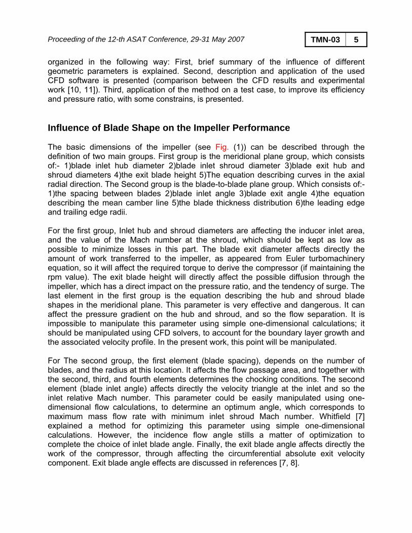
Proceeding of the 12-th ASAT Conference, 29-31 May 2007 TMN-03 5 organized in the following way: First, brief summary of the influence of different geometric parameters is explained. Second, description and application of the used CFD software is presented (comparison between the CFD results and experimental work [10, 11]). Third, application of the method on a test case, to improve its efficiency and pressure ratio, with some constrains, is presented. Influence of Blade Shape on the Impeller Performance The basic dimensions of the impeller (see Fig. (1)) can be described through the definition of two main groups. First group is the meridional plane group, which consists of:- 1)blade inlet hub diameter 2)blade inlet shroud diameter 3)blade exit hub and shroud diameters 4)the exit blade height 5)The equation describing curves in the axial radial direction. The Second group is the blade-to-blade plane group. Which consists of:- 1)the spacing between blades 2)blade inlet angle 3)blade exit angle 4)the equation describing the mean camber line 5)the blade thickness distribution 6)the leading edge and trailing edge radii. For the first group, Inlet hub and shroud diameters are affecting the inducer inlet area, and the value of the Mach number at the shroud, which should be kept as low as possible to minimize losses in this part. The blade exit diameter affects directly the amount of work transferred to the impeller, as appeared from Euler turbomachinery equation, so it will affect the required torque to derive the compressor (if maintaining the rpm value). The exit blade height will directly affect the possible diffusion through the impeller, which has a direct impact on the pressure ratio, and the tendency of surge. The last element in the first group is the equation describing the hub and shroud blade shapes in the meridional plane. This parameter is very effective and dangerous. It can affect the pressure gradient on the hub and shroud, and so the flow separation. It is impossible to manipulate this parameter using simple one-dimensional calculations; it should be manipulated using CFD solvers, to account for the boundary layer growth and the associated velocity profile. In the present work, this point will be manipulated. For The second group, the first element (blade spacing), depends on the number of blades, and the radius at this location. It affects the flow passage area, and together with the second, third, and fourth elements determines the chocking conditions. The second element (blade inlet angle) affects directly the velocity triangle at the inlet and so the inlet relative Mach number. This parameter could be easily manipulated using one-dimensional flow calculations, to determine an optimum angle, which corresponds to maximum mass flow rate with minimum inlet shroud Mach number. Whitfield [7] explained a method for optimizing this parameter using simple one-dimensional calculations. However, the incidence flow angle stills a matter of optimization to complete the choice of inlet blade angle. Finally, the exit blade angle affects directly the work of the compressor, through affecting the circumferential absolute exit velocity component. Exit blade angle effects are discussed in references [7, 8].
Proceeding of the 12-th ASAT Conference, 29-31 May 2007 TMN-03 6 In spite of that, the previous discussion was investigating, the effect of different parameters on the performance of the centrifugal impeller. The actual behavior of the impeller is affected by the combination of the geometrical parameters together, not by every one alone. That limits the ability of trusting empirical, and simple basic equations results. In addition, forces the designers towards the obligatory 3-D CFD solution, which deals with the actual geometry as one unit, combining all the previously mentioned points. THE FLUID FLOW SOLVER The geometrical manipulation of the impeller geometry is done in this work using the commercial software (CFX BladeGen). Where as The CFD solution of the flow inside the impeller is performed using the commercial software (CFX BladeGenPlus version 4.1). This complete package manipulates all the design process. The geometry is first described, and then the grid is generated. Finally, boundary conditions treatment, and the complete CFD solution is performed. CFX software solves the Reynolds-averaged Nervier-Stokes equations. Finite volume method is the discretization method used in this package. The zero-equation turbulence-model is used as a turbulence model in this CFX version. The boundary conditions Treatment are as follows: - At the Inlet, total pressure, and total temperature should be assigned. At the exit, static pressure is used. Mass flow rate should be assigned if (Ps) is not used. Finally, the periodic boundary conditions are imposed by the program (the solution is performed around one blade of the set only). Other required parameters are rpm, surface roughness, fluid properties, and inlet swirling angle (if exists). In addition, the specification of the target residual and maximum number of iterations should be addressed. The physical time step can be chosen by the user, where a value equals (1/ω) is recommended, and it is the program default value. Sensitivity Analysis of CFX Software Before using the program in this work, the program was investigated, to determine its appropriate parameters to be used. The parameters under investigation were grid density in the whole domain, grid density at solid walls, and the target residual. The effect of the previous points on the impeller efficiency, exit pressure, and exit flow coefficient were investigated. 1- Grid Density The grid is completely specified in the CFX software using two parameters (grid refinement factor, grid inflation layer). Clustering is possible around LE and TE. This feature was used in the present work.
a- Grid refinement factor It indicates the grid density to be used in the whole field. A number between 0.01 and 10.0 could be used. Where a value up to 100 is permitted, but not recommended by
Proceeding of the 12-th ASAT Conference, 29-31 May 2007 TMN-03 7
the software manual. Fig. (2) shows the application of different values of grid refinement factor, and its effect on the obtained results. In addition, the effect of number of grid points on the solution is investigated.
b- Grid inflation layer This parameter determines the level of clustering to be imposed on the grid around the blade surface. It is used to handle the boundary layers more accurately -if required-. Fig.(3) shows the effect of varying the GIL value on the obtained results. Noting that, the curve is not purely showing the effect of GIL alone, but also the effect of number of nodes.
2- Target Residual The target residual is the maximum value accepted as a difference in certain parameters (like, velocity components, pressure values) between any iteration and the next one. The solver automatically stops once the target residual has been met for all variables. A target residual of 5E-5 or lower is recommended. Fig.(4) shows the effect of varying the target residual value on the obtained results. A sensitivity analysis was done involving the preceding parameters. The result of the analysis was a recommendation of the following values to be used: 1) A value of (7) for grid refinement factor, 2) A value of (10) for grid inflation layer, 3) a value of (1*E-4) for target residual. The number of grid nodes was about 70,000. In spite of that, higher values of GRF, and lower values of TR will results in better results; the solution will need a longer time. It was decided to use the above values, because the flow structure is nearly the same for both cases, but only the values differ. Bonaiuti [9] did the same action in his optimization process, where used a grid of 70,000 nodes during the optimization, and 350,000 nodes for detailed investigation of the final configurations. Applications of CFX Software The CFX software was used to solve published cases. Khalil [12] used this software for solving the flow field around an axial fan. Comparison between measured and calculated results shows good agreement. Mizuki [10,11], published a detailed measurements of a three centrifugal compressors using yaw probes for measuring total and static pressure along the channel between blades. In spite of that, it is an old case but due to its accuracy, and large data released about it, it was decided to use it as a test case. From the published three impellers (A, B, C), Impeller (A) was chosen for validation and optimization because it is addressed as inefficient compressor, so optimizing such a version case is promising. The impeller geometry is given in table (1). This case was solved using the CFX software. A comparison between measured and calculated values is shown in table (2). Measurements of [11] showed that, the area of shroud at the position of deflection from axial to radial direction had a high relative velocity. The down stream area following is characterized by low velocity. Fig. (6a)
Proceeding of the 12-th ASAT Conference, 29-31 May 2007 TMN-03 8 coincides with these measurements, which also insists on the accuracy and validity of the (CFX BladeGen) software. THE OPTIMIZATION PROBLEM The optimization problem elements are as follows: 1) parametrizing the geometry, 2) handling the parameters via the optimizer, 3) solving using CFD. In the present work, a free published library called GaLib245 [13] was used as optimizer. (1) Geometry Parameterization The impeller geometry should be casted in a suitable form to facilitate its handling by the optimizer. The impeller parameterization was as follows: four points are used to define a Bezier curve describing the hub, each point is defined by (z and r) coordinates. Same number of points for the shroud was used. The input channel length was determined by the difference in axial coordinates between the input channel point and the first point in the impeller shroud curve. The input channel diameter takes the same value of the shroud first point diameter. That is to assure the straightness of the inlet channel. The exit channel axial location takes the value of the impeller hub/shroud last points. After parameterization the impeller is now looks like a paste, where choosing the coordinates of only eight points (in addition of four points for inlet and outlet) will immediately draw a new impeller meridional shape. That is to say, now the number of input parameters is 16 to be manipulated through an optimizer. (2) Genetic Algorithm Optimizer Simply the Genetic Algorithm is an optimization tool, which cast the variables in groups (genes and chromosomes), then dealing with the problem under investigation through some operators (crossover, and mutation). The optimization process starts by randomly combining parents -for the first generation only- from given set called population, then forming an offspring from the selected parents. The process continued through the next generations (combining parents to produce offspring). However, the difference in the next generations is that, the chance of every parent to meet a partner is depending on his rank. Where the rank of every member of the population is determined according to its matching to certain given cost function. That is to say, members of higher ranks have more opportunities to have children, than other members. That coincides with the concept of survival of the fittest. The evolution continues from generation to the other until termination criteria is met. (3) Operators The genetic algorithm operators are crossover and mutation. Crossover is a process of forming an offspring by, combining a part of the first parent, with a compliment completes its length from another parent. The percentage of crossover is commonly
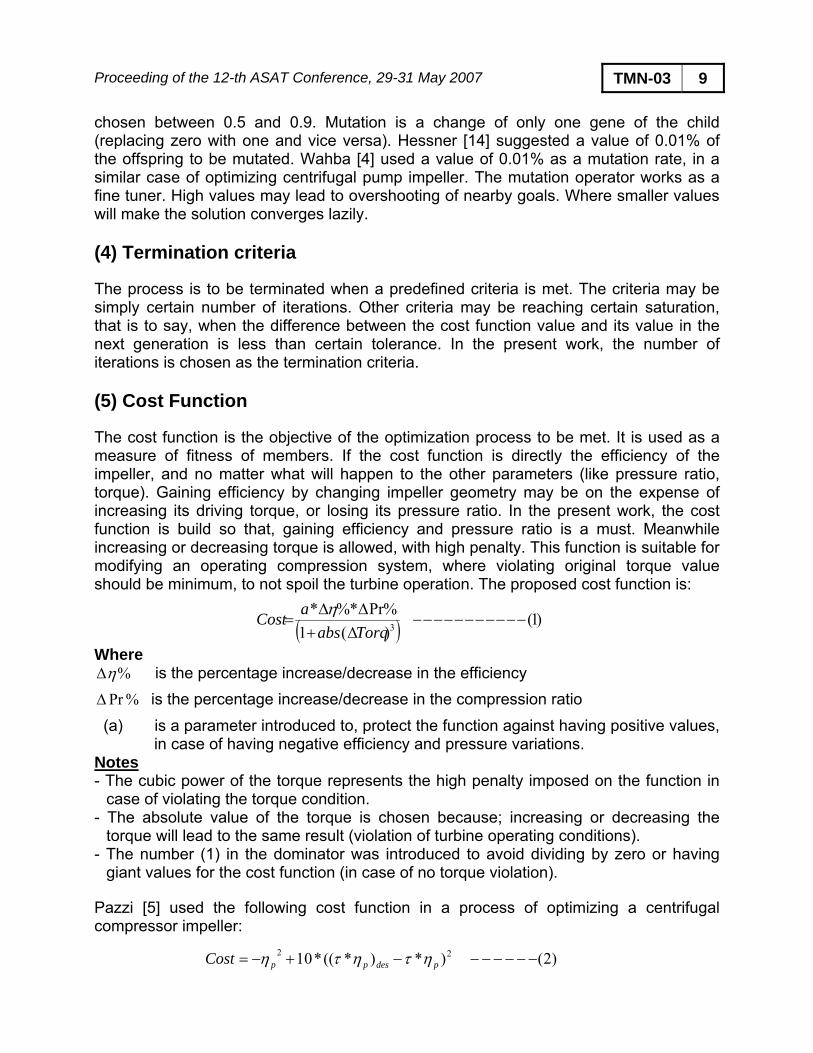
Proceeding of the 12-th ASAT Conference, 29-31 May 2007 TMN-03 9 chosen between 0.5 and 0.9. Mutation is a change of only one gene of the child (replacing zero with one and vice versa). Hessner [14] suggested a value of 0.01% of the offspring to be mutated. Wahba [4] used a value of 0.01% as a mutation rate, in a similar case of optimizing centrifugal pump impeller. The mutation operator works as a fine tuner. High values may lead to overshooting of nearby goals. Where smaller values will make the solution converges lazily. (4) Termination criteria The process is to be terminated when a predefined criteria is met. The criteria may be simply certain number of iterations. Other criteria may be reaching certain saturation, that is to say, when the difference between the cost function value and its value in the next generation is less than certain tolerance. In the present work, the number of iterations is chosen as the termination criteria. (5) Cost Function The cost function is the objective of the optimization process to be met. It is used as a measure of fitness of members. If the cost function is directly the efficiency of the impeller, and no matter what will happen to the other parameters (like pressure ratio, torque). Gaining efficiency by changing impeller geometry may be on the expense of increasing its driving torque, or losing its pressure ratio. In the present work, the cost function is build so that, gaining efficiency and pressure ratio is a must. Meanwhile increasing or decreasing torque is allowed, with high penalty. This function is suitable for modifying an operating compression system, where violating original torque value should be minimum, to not spoil the turbine operation. The proposed cost function is:
( ) )1()(1%Pr*%*
3 −−−−−−−−−−−Δ+ΔΔ
=Torqabs
aCost η
Where %ηΔ is the percentage increase/decrease in the efficiency
%PrΔ is the percentage increase/decrease in the compression ratio
(a) is a parameter introduced to, protect the function against having positive values, in case of having negative efficiency and pressure variations.
Notes - The cubic power of the torque represents the high penalty imposed on the function in
case of violating the torque condition. - The absolute value of the torque is chosen because; increasing or decreasing the
torque will lead to the same result (violation of turbine operating conditions). - The number (1) in the dominator was introduced to avoid dividing by zero or having
giant values for the cost function (in case of no torque violation). Pazzi [5] used the following cost function in a process of optimizing a centrifugal compressor impeller:
)2()*)*((*10 22 −−−−−−−+−= pdesppCost ητητη
Proceeding of the 12-th ASAT Conference, 29-31 May 2007 TMN-03 10
method
he proposed method was applied to a twelve radial bladed impeller of Mizuki [11]. The
ESULTS AND DISCUSSION
igures (6, 7) revealed the secret of efficiency, and pressure-ratio improvement, as a
or the meridional Mach number distribution, Figure (6a, 6c) shows the contours of
ase shows a high Mach number zone at the inducer
Application of the Toptimization target was to increase its efficiency, and its pressure ratio, as much as possible. Constant mass flow rate, constant rpm were applied as constrains, while torque violation hoped to not exceed 1%. The used population size, number of generations, mutation rate, and crossover rate were 30, 75, 0.01, and 0.6 respectively. The optimizer took about 1156 iteration, along 192 hour, to achieve the optimum. The machine used was, AMD Athlon 5200, 2.6 GHZ, 2 M L2cash. A comparison between the initial and final cases is shown in Fig. (5). A comparison between vector plotting, contours of Mach number, for both original and modified impellers was shown in Fig.(6), Fig.(7). The comparison contains both meridional and blade-to-blade planes. R Fresult of the optimization process. The optimizer found the best geometrical configuration, which minimized the flow separation, vortices, and reduces the high Mach number gradients. It should be noted that, in spite of that the optimization was carried out in the meridional plane only, its effect smears also in the m-ө plane, due to the 3-D nature of the flow. The variation in channel height will mean a change of the cross-sectional area and so velocities in both planes. In addition, the change in LE and TE lean angle means direct effect on m-ө plane. In the following paragraph, the impact of optimization process on the flow structure will be discussed. FMach number at stations 0%, 25%, 75% of the distance from periodic surfaces, for the original and optimized configurations. The following comments are observed:
t station 0%, for the original case, the figure shows a high Mach number zone, at theAshroud side in the axial radial bend location, which was explained as a main source of inefficiency in [11]. It is clear that the velocity profile become smoother in this location at the optimized impeller fig (6c).
AT station 25%, the original cshroud inlet. Whitfield [7] discussed the bad effect of high inlet relative Mach number, and described it as a big source of inefficiency. Figure (6c) shows that after optimization, the inlet relative Mach number has been lowered. In addition, the original impeller shows a partially stagnant zone at the shroud outlet fig (6a), neighbored by a relatively high speed (at the hub side). The high deference in velocity represents the jet wake pattern, which is addressed as a main source of deficiency for both impeller and diffuser. The consequences of this problem are clearer in the vector-plotting, fig (6b). A flow separation and flow reattachment appeared in the typical area, it represents a source of energy dissipation in non-useful work.
Proceeding of the 12-th ASAT Conference, 29-31 May 2007 TMN-03 11 At station 75%, there is no obvious problem in the flow structure of the original case. In addition, no variation occurred between original and optimized cases. For the blade-to-blade Mach number distribution, Fig. (7a, 7c) shows the Mach number contours for both original and optimized impellers, at stations 10%, 50%, 90% of the distance from hub to shroud. Whereas Fig. (7b, 7d) shows vector plotting for the original and optimized shapes at the same stations. The following comments are observed:
At station 10%, No big difference could be noticed, between the original and optimized cases. The only issue is the slightly high Mach number at the inducer leading edge Fig. (7a). After optimization, and due to increasing blade height (for the same mass flow rate), it is logical to find a decrease in the inlet relative Mach number.
At station 50%, two problems start to appear in the original design. The first one is the relatively high inlet relative Mach number Fig. (7a). Whereas the second problem is the relatively low Mach number at the TE of the blade upper surface, moderate Mach number at the TE lower surface. This distribution represents the jet-wake pattern in this plane. Again, this is a famous source of deficiency as descried before. After optimization, Fig. (7c) shows enhancement in both problems.
At station 90%, the two previously mentioned problems in the original configuration are now exaggerated. High Mach number exists at the inducer leading edge, and very big stagnant zone at the TE upper surface. A violent jet-wake structure appears. A big vortex exists at the end of the upper blade surface. The flow structure is as bad as possible in the whole impeller. For the optimized geometry (figure 7c, 7d), no such pattern exists, which means a big improvement in the efficiency. CONCLUSION A method for optimizing Centrifugal compressor impellers was developed. The method combines a genetic algorithm (as an optimizer), with a three-Dimensional viscous fluid flow solver. The optimization problem was to maximize the efficiency and pressure ratio, while keeping closeness to the original torque value (deviation about 1%), and constant mass flow rate. This method is recommended when modifying the compressor of an operating system. The method was applied to Impeller (A) of reference [10]. The results show an efficiency improvement of 12.8%, and pressure ratio increase of 0.12 %, with a torque violation of only 0.66% occurred. This satisfies the requirements of the paper, to have better efficiency, and pressure ratio, with the lowest possible torque violation. ACKNOWLEDGEMENT The author would like to express his appreciation to EAE Technology (The owner company of CFX software), and Wall, M. the author of GAlib245. These packages were a powerful tools without which, this work would never been accomplished.
Proceeding of the 12-th ASAT Conference, 29-31 May 2007 TMN-03 12 REFERENCES [1] Oana, M. O., Kawamoto, H. Ohtani, and Yamamoto, Y., “Approach to High-
Performance Transonic Compressor Design”. AIAA. journal Of Propulsion And Power Vol. 20, No. 1, January–February (2004).
[2] Yiu K.F.C. and Zangeneh,M. ”Three Dimensional Automatic Optimization Method For Turbomachenery Blade Design”, AIAA, journal of propulsion and power Vol 16 No.6 November-December (2000).
[3] Ernesto Benini, “Three dimentional Multi-objective Design Optimization of a transonic compressor rotor”. AIAA, jurnal of propulsion and power VOL. 20, No. 3, May-June (2004).
[4] Wahba, W. A., and Tourlidaks, A.,”A Genetic Algorithm to Design a Blade Profiles for Centrifugal Pump Impellers”, AIAA Paper 2001-2582 (2001).
[5] Simone Pazzi, Francesco Martelli, Vittorio Michelassi, Marco Giachi , Frank Van Den BBerghen, Hugues Bersini, “Inteligent Performance CFD Optimization of A Centrifugal Impeller”, Department of Energetics -University of Florance- Florance, Italy. E-mail: [email protected], [email protected].
[6] Summers, S. M., “Developing Centrifugal Compressor Train Optimization Models for performance Evaluation”, ASME, 322/Vol. 120. April (1998).
[7] Whitfield,A., Banes N.C., “Design of radial turbomachines”, Longman Group UK limited (1990).
[8] Ecardt D. ,“Flow Field Analysis of Radial and Back swept Centrifugal Compressor Impellers Part 1: Flow Mesurements Using a Laser Velocimeter” symposium on performance Predection of Centrifugal Pumps & Compressors, (1980).
[9] Bonaiuti, D. Arnon, A. Ermini M, “Analysis and optimization of Transonic Centrifugal Compressor Impeller Using The Design of experiment Technique” ASME June 3-6 (2002).
[10] Shimple Mizuki, Ichiro Ariga, Ichiro Watanabe. “Investigations Concerning the Blade Loading of Centrifugal Impellers” ASME T4-GT-143, December 1974.
[11] Shimple Mizuki, Ichiro Ariga, Ichiro Watanabe. “A Study of Flow Mechanizm within Centrifugal Impeller Channel” ASME T4-GT-14, December (1975).
[12] Khalil, M. K. “Automation of wind Tunnel Operation”, Thesis of Master of Science Cairo 2003.
[13] Wall M., “GAlib: A C++ Library of Genetic Algorithm Components”, version 2.4, Massachusetts Institute of Technology, USA, (1996)
[14] Hessner J. and Männer R., “Choosing Optimal Mutation Rates”, in Proceedings of the First Workshop on Parallel Problem Solving from Nature (Lecture Notes in Computer Science, Vol. 496); P. Schwefel and R. Männer (Eds.); Springer- Verlag: Berlin, 1991, pp 23-31, (1991).