Page 1
Saimaa University of Applied Sciences Technology, Lappeenranta Double Degree Program in Civil and Construction Engineering
Lustina Olga
THREE-PINNED GLUED-LAMINATED FRAME Bachelor’s Thesis 2017
Page 2
1
ABSTRACT Olga Lustina Three-pinned glued-laminated frame, 38 pp, 2 appendices Saimaa University of Applied Sciences, Lappeenranta Technology, DDCIV16 Bachelor’s Thesis, 2017 Tutor: Timo Lehtoviita, Lecturer in Saimaa University of Applied Sciences The subject of the thesis was to design the Three-pinned glued-laminated frame for the sport centre with the use of modern software. All calculations are made according to European standards (EN 1990: 2002 + A1, EN 1991-1-1, EN 1991-1-3, EN 1991-1-4: 2005 + A1, EN 1995-1-1: 2004 + A1) and Finnish National Annex. Glulam characteristics are taken from EN 14080.
Imposed loads are collected manually and applied in SCAD Office software. Cross section is chosen automatically in a special program created in Mathcad soft. According to the result of calculations, a 3D model of the structure is made with ARCHICAD software.
Thus, the main purpose to create a Mathcad program for choosing the cross sec-tion of three-pinned glued-laminated frame (including tapered sections) was achieved. This invention can significantly reduce the designing time.
Key words: construction design, structure, three-pinned frames, long-span, glued-laminated timber, Mathcad calculations, SCAD calculations, 3D AR-CHICAD models.
Page 3
2
CONTENTS
TERMINOLOGY ................................................................................................ 3
1 GENERAL INFORMATION ABOUT GLUED-LAMINATED TIMBER ............... 5
2 INTRODUCTION ......................................................................................... 8
3 DESIGNING METHODS ............................................................................. 9
4 CALCULATIONS ....................................................................................... 11
4.1 Actions on the structure ...................................................................... 11
4.2 Partial factor method ........................................................................... 12
4.3 Initial data ........................................................................................... 12
4.4 Collecting loads .................................................................................. 14
4.4.1 Permanent actions (G) .................................................................... 14
4.4.2 Variable actions (Q) ......................................................................... 14
4.4.3 Combination of actions .................................................................... 22
5 MODELING ............................................................................................... 25
6 CONCLUSIONS ........................................................................................ 26
REFERENCES ................................................................................................ 27
APPENDICES ................................................................................................. 28
Appendix 1. Mathcad calculations ................................................................ 28
Appendix 2. 3D model of the building ........................................................... 37
Page 4
3
TERMINOLOGY
μi - the snow load shape coefficient
Ce - exposure coefficient,
Ct – thermal coefficient
sk - characteristic value of snow on the ground at the relevant site
Fs - the force exerted by a sliding mass of snow, in the direction of slide, per unit length of the building
s - the snow load on the roof relative to the most onerous undrifted load case appropriate for roof area from which snow could slide
b - the width on plan (horizontal) from the guard or obstacle to the next guard or to the ridge
α - a pitch of the roof, measured from the horizontal
Vb - the basic wind velocity
Vb,Q - the fundamental value of the basic wind velocity
Cdir - the directional factor
Cseason - the season factor
vm(z) - the mean wind velocity at a height z above the terrain
cr(z) - the roughness factor
co(z) - the orography factor
zo - the roughness length
kr - terrain factor depending on the roughness length zo
zmin - the minimum height
σv - the standard deviation of the turbulence
kl - the turbulence factor
qp(z) - the peak velocity pressure at height z
ρ - the air density
ce(z) - the exposure factor
qb - the basic velocity pressure
we - the wind pressure acting on the external surfaces
ze - the reference height for the external pressure
Page 5
4
cpe - the pressure coefficient for the external pressure
Qsp – maximum shear force in spans
Qsup – maximum shear force on supports
σc,o,d – design compressive stress along the grain
fc,o,d – design compressive strength along the grain
fc,o,k – characteristic compressive strength along the grain
ft,o,d – design tensile strength along the grain
ft,o,k – characteristic tensile strength along the grain
Nr – lateral force in the ridge
S – length of the frame along the axis
F – section area
I – moment inertia
W – section modulus
fm,k – characteristic bending strength
E – mean Young’s modulus
E0.05 – 5% value of mean Young’s modulus
G – shear modulus parallel to the grain
G0.05 – 5% value of shear modulus parallel to the grain
Itor – torsional moment of inertia
l – span length
lef – effective length
σm,crit – critical bending stress
λrel,m – relative slenderness for bending
rin – the inner radius of curved beam
λz – slenderness ratio corresponding to bending about z-axis
σm,d – design bending stress
fm,k – characteristic bending strength
fm,d – design bending strength
hap – depth of beam at the apex
τd – design shear stress
fv,d – design bending strength
S’ – static momentum of the cross-section
Page 6
5
1 GENERAL INFORMATION ABOUT GLUED-LAMINATED TIM-
BER
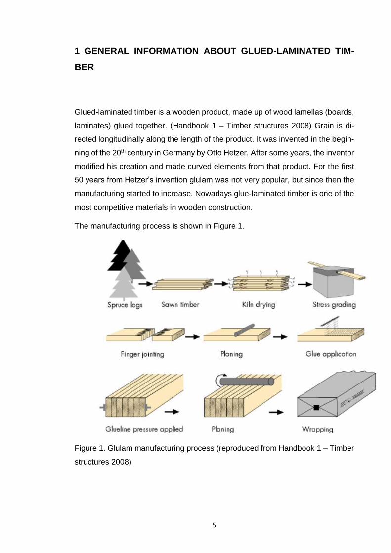
Glued-laminated timber is a wooden product, made up of wood lamellas (boards,
laminates) glued together. (Handbook 1 – Timber structures 2008) Grain is di-
rected longitudinally along the length of the product. It was invented in the begin-
ning of the 20th century in Germany by Otto Hetzer. After some years, the inventor
modified his creation and made curved elements from that product. For the first
50 years from Hetzer’s invention glulam was not very popular, but since then the
manufacturing started to increase. Nowadays glue-laminated timber is one of the
most competitive materials in wooden construction.
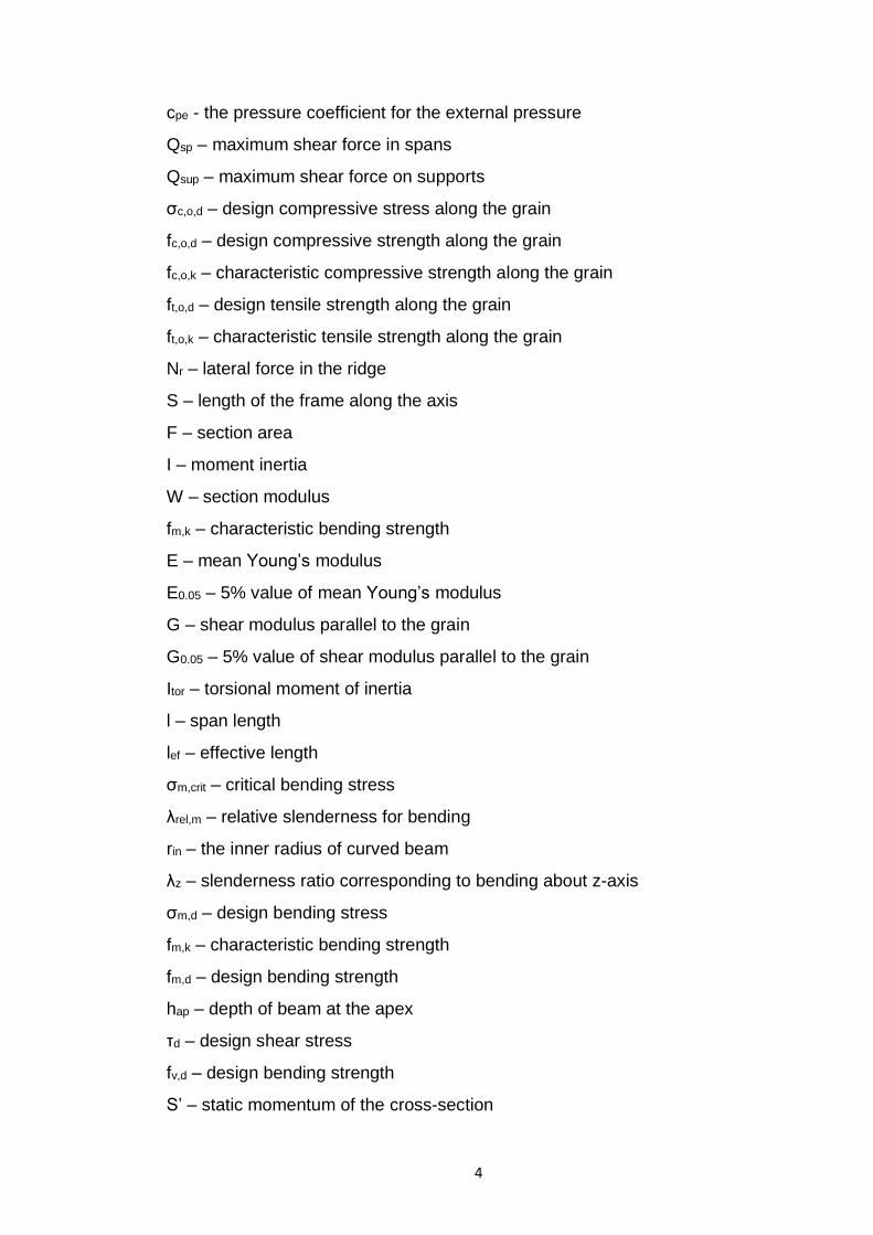
The manufacturing process is shown in Figure 1.
Figure 1. Glulam manufacturing process (reproduced from Handbook 1 – Timber
structures 2008)
Page 7
6
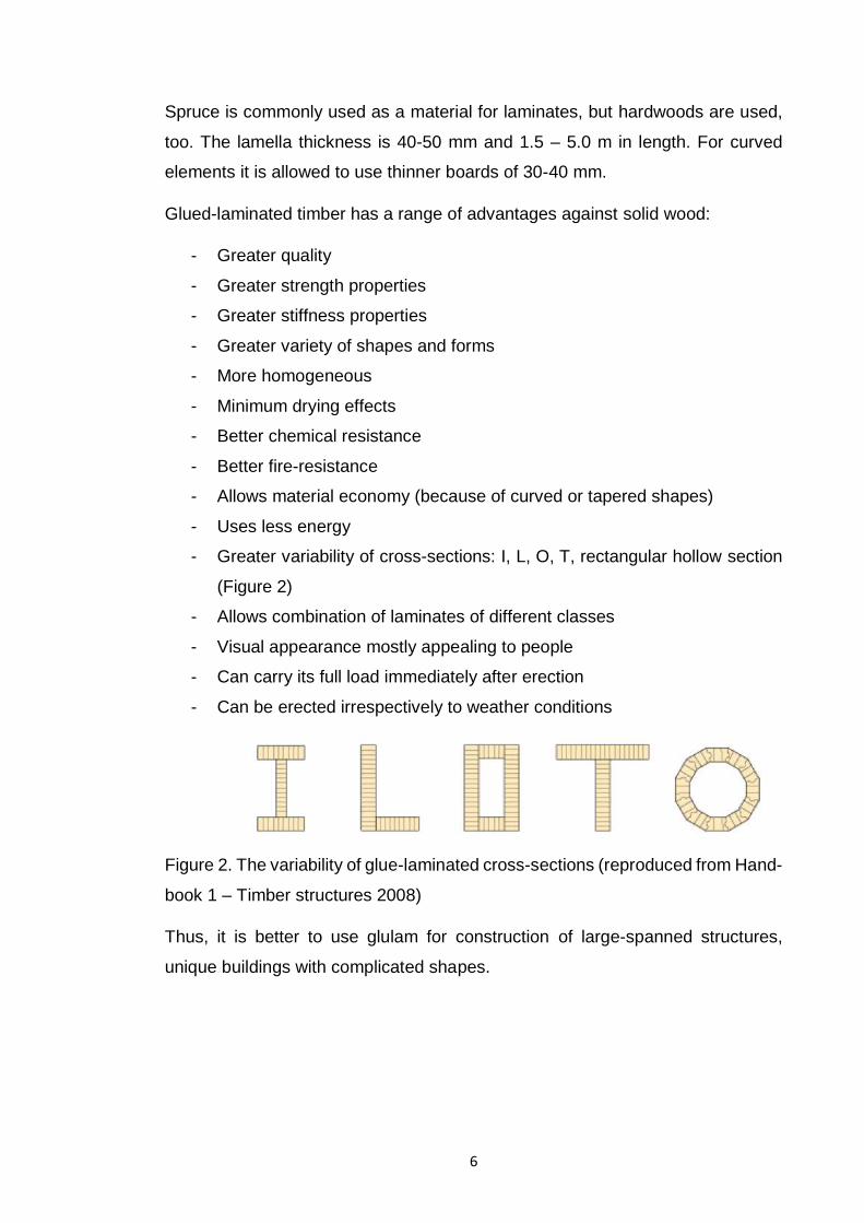
Spruce is commonly used as a material for laminates, but hardwoods are used,
too. The lamella thickness is 40-50 mm and 1.5 – 5.0 m in length. For curved
elements it is allowed to use thinner boards of 30-40 mm.
Glued-laminated timber has a range of advantages against solid wood:
- Greater quality
- Greater strength properties
- Greater stiffness properties
- Greater variety of shapes and forms
- More homogeneous
- Minimum drying effects
- Better chemical resistance
- Better fire-resistance
- Allows material economy (because of curved or tapered shapes)
- Uses less energy
- Greater variability of cross-sections: I, L, O, T, rectangular hollow section
(Figure 2)
- Allows combination of laminates of different classes
- Visual appearance mostly appealing to people
- Can carry its full load immediately after erection
- Can be erected irrespectively to weather conditions
Figure 2. The variability of glue-laminated cross-sections (reproduced from Hand-
book 1 – Timber structures 2008)
Thus, it is better to use glulam for construction of large-spanned structures,
unique buildings with complicated shapes.
Page 8
7
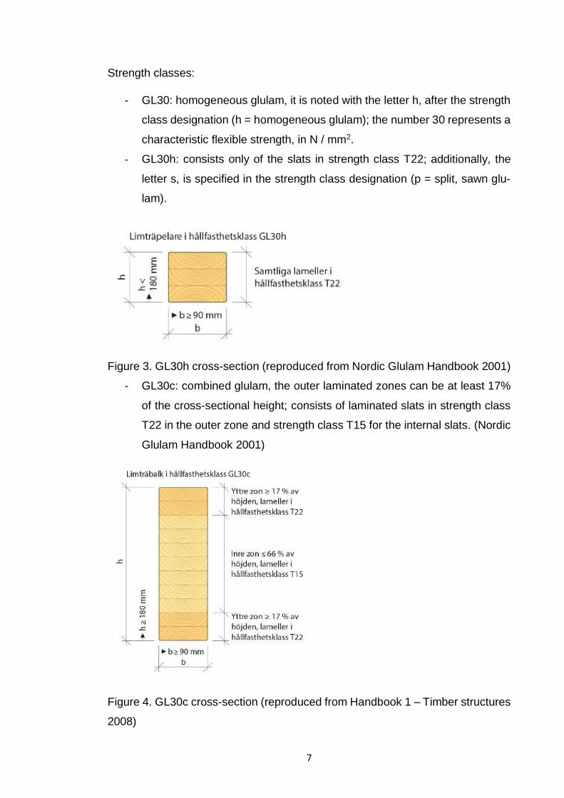
Strength classes:
- GL30: homogeneous glulam, it is noted with the letter h, after the strength
class designation (h = homogeneous glulam); the number 30 represents a
characteristic flexible strength, in N / mm2.
- GL30h: consists only of the slats in strength class T22; additionally, the
letter s, is specified in the strength class designation (p = split, sawn glu-
lam).
Figure 3. GL30h cross-section (reproduced from Nordic Glulam Handbook 2001)
- GL30c: combined glulam, the outer laminated zones can be at least 17%
of the cross-sectional height; consists of laminated slats in strength class
T22 in the outer zone and strength class T15 for the internal slats. (Nordic
Glulam Handbook 2001)
Figure 4. GL30c cross-section (reproduced from Handbook 1 – Timber structures
2008)
Page 9
8
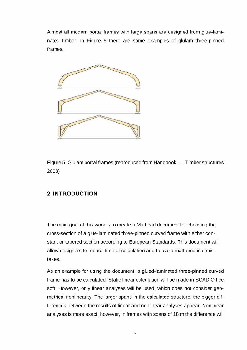
Almost all modern portal frames with large spans are designed from glue-lami-
nated timber. In Figure 5 there are some examples of glulam three-pinned
frames.
Figure 5. Glulam portal frames (reproduced from Handbook 1 – Timber structures
2008)
2 INTRODUCTION
The main goal of this work is to create a Mathcad document for choosing the
cross-section of a glue-laminated three-pinned curved frame with either con-
stant or tapered section according to European Standards. This document will
allow designers to reduce time of calculation and to avoid mathematical mis-
takes.
As an example for using the document, a glued-laminated three-pinned curved
frame has to be calculated. Static linear calculation will be made in SCAD Office
soft. However, only linear analyses will be used, which does not consider geo-
metrical nonlinearity. The larger spans in the calculated structure, the bigger dif-
ferences between the results of linear and nonlinear analyses appear. Nonlinear
analyses is more exact, however, in frames with spans of 18 m the difference will
Page 10
9
be insignificant. Besides, in this work joints are not designed. Only one specific
load case is considered.
Additionally, a 3D model of the designed structure will be made in ARCHICAD.
3 DESIGNING METHODS
As a main designing tool, SCAD Office soft was used. SCAD Office is a new
generation system developed by engineers for engineers and implemented by a
team of experienced programmers. The system includes a high-performing com-
puter complex SCAD, as well as a number of design and support programs that
allow to solve complex problems of calculation and design of steel and reinforced
concrete structures. The system is constantly developing, the user interface and
computing capabilities are improving and new design components are included.
All calculation and designing methods are complied with SNIPs (Russian con-
struction standards). However, it is possible to make calculations according to
Eurocodes by entering user’s coefficients and combinations of actions.
SCAD Office includes the following programs:
- SCAD - a computational complex for strength analysis of structures by the
finite element method.
- Kristall - calculation of elements of steel structures
- ARBAT - selection of fittings and expertise of elements of reinforced con-
crete structures
- COMEIN - calculation of stone and reinforced structures
- Decor - calculation of wooden structures
- Zapros - calculation of foundations and their elements
- SLOPE - analysis of the stability of slopes
- WeST - calculation of loads by SNiP "Loads and effects" and DBN (does
not applicatible for EN)
- Monolit - design of monolithic ribbed floors
- Comet - calculation and design of steel structures
Page 11
10
- Cross - calculation of the bed coefficients of buildings and structures on
an elastic foundation
- Section Designer - forming and calculation of geometrical characteristics
of sections from rolling profiles and sheets
- Consul - construction of arbitrary sections and calculation of their geomet-
ric characteristics on the basis of the theory of solid rods
- Tonus - construction of arbitrary sections and calculation of their geometric
characteristics on the basis of the theory of thin-walled rods
- Sezam - search for equivalent sections
- CoCon - a guide to stress concentration coefficients and stress intensity
factors
- KUST - the theoretical calculation guide of the designer
United graphical environment for the synthesis of the calculation scheme and
analysis of the results provides unlimited possibilities for modeling the calculation
schemes from the simplest to the most complex structures, satisfying the needs
of experienced professionals and while still available to beginners.
A high-performance processor allows solving large-scale problems (hundreds of
thousands of degrees of freedom under static and dynamic effects).
SCAD includes a developed finite element library for modeling rod, plate, solid
and combined structures, stability analysis modules, forming designing combina-
tions of forces, testing the stress state of structural elements in various strength
theories, determining the interaction forces of the element with the rest of the
structure, calculating the forces and displacements from load combinations. The
complex includes programs for selecting reinforcement in elements of reinforced
concrete structures and checking the cross-sections of elements of steel.
The program allows import of geometry from ArchiCAD, AutoCAD HyperSteel,
and other soft producing data in DXF, DWG formats.
The calculation results are displayed both in graphical and tabular forms, which
makes the understanding easier. For rod elements, deformed schemes can be
obtained considering deflections and deflection diagrams for individual elements.
Page 12
11
The forces in the rod elements are represented in the form of diagrams for the
entire scheme or individual element, as well as the color indication of the maxi-
mum values of the selected force factor.
Forces and stresses in plate and volume elements are displayed in the form of
isofields or isolines in the specified range of the color scale with the ability to
display numerical values at the centers and nodes of the elements simultane-
ously.
The calculation results in a tabular form can be exported to the MS Word or MS
Excel for easy editing and calculating.
The table presentation of the results can be supplemented with graphical materi-
als selected in the process of creating the calculation scheme and analyzing the
results.
SCAD provides data exchange with other programs using universal formats as
IFC, CIS / 2, DXF, DWG (Advance Steel program data formats versions 2014,
2015, 2016, ANSYS, STAAD, Abacus, Femap, GMSH, NetGen; plugins for Revit
programs versions 2013, 2014,2015, 2016, ArchiCAD versions 16,17,18, Tekla
versions 18 19 20 21). (SCAD official web-site 2017)
4 CALCULATIONS
4.1 Actions on the structure
All actions are imposed according to European Standards. As permanent actions
(G) is taken the self-weight of the main bearing structure and the self-weight of
the glazed roof structure. Variable actions are: wind and snow actions in Lap-
peenranta. Accidental actions are not considered.
The variability of G is neglected, because it does not vary significantly. The self-
weight of the structure is represented by a single characteristic value and it is
calculated on the basis of the normal dimensions and mean unit masses.
Page 13
12
For variable actions the characteristic value is taken as an upper value with an
intended probability is not being exceeded. The combination values of variable
actions (ψ0Qk) are used for the verification of ultimate limit states and irreversible
limit states.
4.2 Partial factor method
Verifications are made by partial factor method. It checks that in all relevant de-
sign situations, no relevant limit state is exceeded when design values for actions
or effects of actions and resistances are used in the design model. For these
calculations and the relevant limit states, the individual actions for the critical load
cases are combined with relevant coefficients.
Design values are obtained by using characteristic values multiplied by relevant
factor. (According to EN 1990:2002+A1:2005)
In this work STR limit state is verified as following: internal failure or excessive
deformation of the structure.
4.3 Initial data
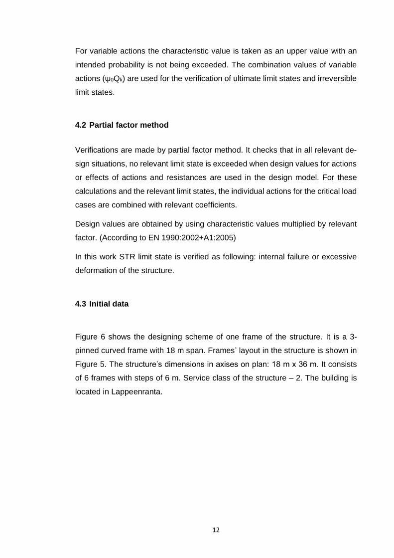
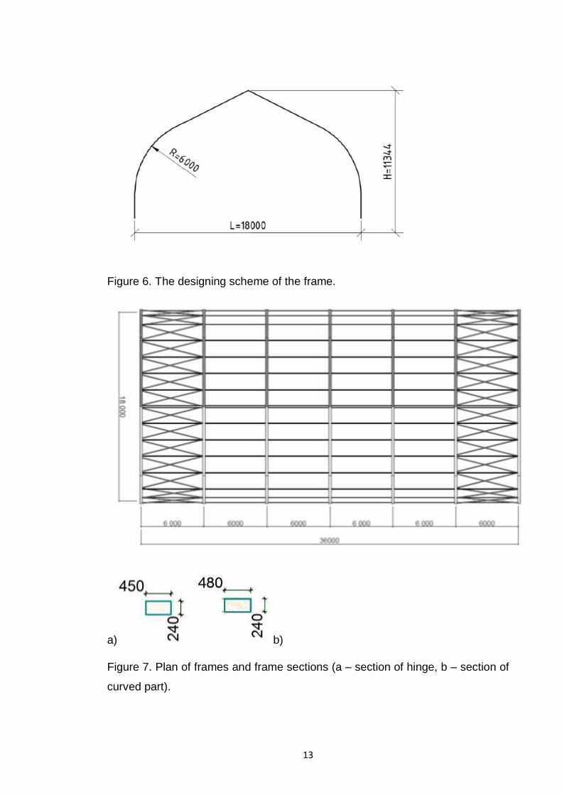
Figure 6 shows the designing scheme of one frame of the structure. It is a 3-
pinned curved frame with 18 m span. Frames’ layout in the structure is shown in
Figure 5. The structure’s dimensions in axises on plan: 18 m x 36 m. It consists
of 6 frames with steps of 6 m. Service class of the structure – 2. The building is
located in Lappeenranta.
Page 14
13
Figure 6. The designing scheme of the frame.
a) b)
Figure 7. Plan of frames and frame sections (a – section of hinge, b – section of
curved part).
Page 15
14
Glulam characteristics (according to EN 14080):
Class of resistance - GL32h
Bending strength fm,k - 35 MPa
Compressive strength fc,o,k - 31 MPa
Tensile strength ft,o,k - 24 MPa
Chipping strength - 4,8 MPa
Mean Young’s modulus E - 13500 MPa
Shear modulus parallel to grain G - 350 MPa
4.4 Collecting loads
4.4.1 Permanent actions (G)
This kind of actions are automatically created by SCAD program.
4.4.2 Variable actions (Q)
Snow load
Roof category: H - roofs not accessible except for normal maintenance and re-
pair.
Snow loads [kN/m2] on roofs are determined as follows:
s = μiCeCtsk (1)
Where:
μi - the snow load shape coefficient
Ce - exposure coefficient,
Ct – thermal coefficient
sk - characteristic value of snow on the ground at the relevant site [kN/m2]
Ce - for normal topography (as in Lappeenranta) is 1,0.
sk - for Lappeenranta is 2,75 kN/m2
Page 16
15
Ct = 0,8
μ1 - for pitched roof when snow is not prevented from sliding off the roof, angle of
pitch of roof 30° ≤ α ≤ 60° and for cylindrical roof is 0,8(60 - α)/30. (α = 33°)
μ1 = 0,8 · (60 – 33) / 30 = 0,72 (2)
The force Fs exerted by a sliding mass of snow, in the direction of slide, per unit
length of the building should be taken as:
Fs = s b sin α (3)
Where:
s - the snow load on the roof relative to the most onerous undrifted load case
appropriate for roof area from which snow could slide
b - the width on plan (horizontal) from the guard or obstacle to the next guard or
to the ridge
α - a pitch of the roof, measured from the horizontal
s = 0,72 · 1 · 0,8 · 2,75 = 1,58 kN/m2
Fs = 1,58 · 6 · sin 33° = 5,21 kN
Wind load
Terrarian cathegory - II
The basic wind velocity is calculated from Expression:
Vb = Cdir · Cseason · Vb,O (4)
Where:
Vb - the basic wind velocity, defined as a function of wind direction and time of
year at 10 m above ground of terrain category II
Vb,Q - the fundamental value of the basic wind velocity
Cdir - the directional factor
Cseason - the season factor.
For Finland vb,0 = 21 m/s. The recommended value of Cdir and Cseason is 1,0.
Page 17
16
Vb = 1 · 1 · 21 = 21 m/s.
The mean wind velocity vm(z) at a height z above the terrain depends on the
terrain roughness and orography and on the basic wind velocity, vb, and should
be determined using Expression:
vm(z) = cr(z) · co(z) · vb (5)
Where:
cr(z) - the roughness factor
co(z) - the orography factor, taken as 1,0
c𝑟(z) = 𝑘𝑡 · ln(𝑧
𝑧0) (6)
Where:
zo - the roughness length ( = 0,05 m for terrain category II)
kr - terrain factor depending on the roughness length zo calculated using
k𝑟 = 0,19 ·(𝑧0
𝑧0,𝐼𝐼)0,07 (7)
Where:
zO,II = 0,05 m (terrain category II)
zmin - the minimum height defined (= 2 m for terrain category II)
zmax = 200 m
k𝑟 = 0,19 · (0,05
0,05)0,07
= 0,19
c𝑟(z) = 0,19 · ln (11,34
0,05) = 1,03
vm(z) = 1,03 · 1 · 21 = 21,63 m/s
The standard deviation of the turbulence σv may be determined using Expression:
σv = k𝑟 · vb · k𝑙 (8)
Where:
kl - the turbulence factor (the recommended value for kl is 1,0)
Page 18
17
σv = 0,19 · 21 · 1 = 3,99 m/s
𝑙𝑣(𝑧) =𝜎𝑣
𝑣𝑚(𝑧)=
3,99
21,63= 0,18 (9)
The peak velocity pressure qp(z) at height z:
𝑞𝑝(𝑧) = [1 + 7 · 𝑙𝑣(𝑧)] ∙1
2∙ 𝜌 ∙ 𝑣𝑚
2 (𝑧) = 𝑐𝑒(𝑧) ∙ 𝑞𝑏 (10)
Where:
ρ - the air density, which depends on the altitude, temperature and barometric
pressure to be expected in the region during wind storms (1,25 kg/m3)
ce(z) - the exposure factor given in Expression:
𝑐𝑒(𝑧) =𝑞𝑝(𝑧)
𝑞𝑏 (11)
qb - the basic velocity pressure given in Expression:
qb =1
2∙ ρ ∙ vb
2 =1
2∙ 1,25 ∙ 212 = 0,28kN/m2
qp(z) = [1 + 7 · 0,18] ∙1
2∙ 1,25 ∙ 21,632 = 0,66kN/m2
𝑐𝑒(𝑧) =0,66
0,28= 2,4
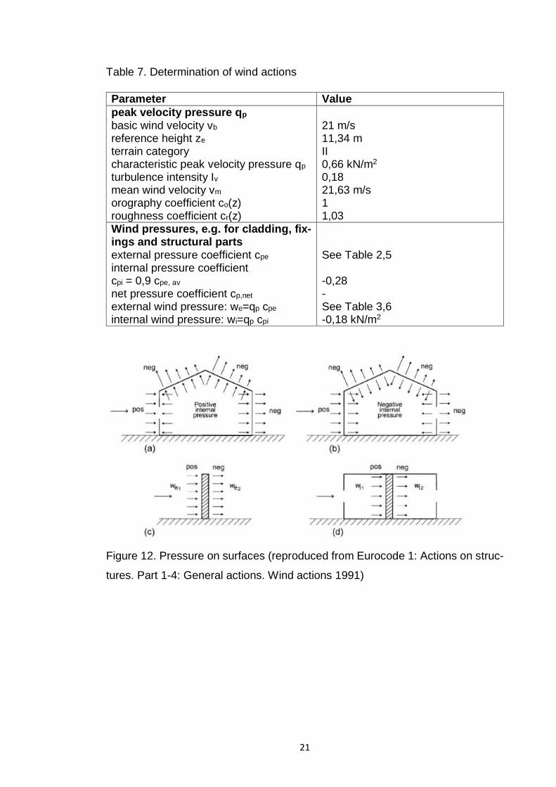
Wind loads on walls
The wind pressure acting on the external surfaces, we, should be obtained from
Expression:
we = qp(ze) · cpe (12)
Where:
qp(ze) - the peak velocity pressure
ze - the reference height for the external pressure
cpe - the pressure coefficient for the external pressure
Page 19
18
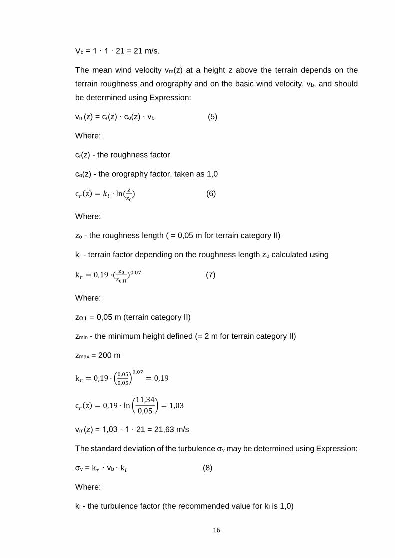
Figure 8. Key 1 for collecting wind loads on walls (reproduced from Eurocode 1:
Actions on structures. Part 1-4: General actions. Wind actions 1991)
h/d = 11,34/18 = 0,63 =>
Table 1. cpe,10 and cpe,1 for walls.
Zone A B
cpe,10 -1,2 -0,8
cpe,1 -1,4 -1,1
cpe = cpe,1 – (cpe,1 - cpe,10)log10A:
Table 2. cpe for walls.
Zone A B
cpe -1,06 -0,24
e = 2h = 22,69 m, e > d: (13)
Page 20
19
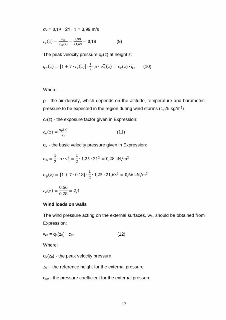
Figure 9. Key 2 for collecting wind loads on walls (reproduced from Eurocode 1:
Actions on structures. Part 1-4: General actions. Wind actions 1991)
we = 660,85 · cpe, Pa: (14)
Table 3. we for walls.
Zone A B
we -700,5 -158,6
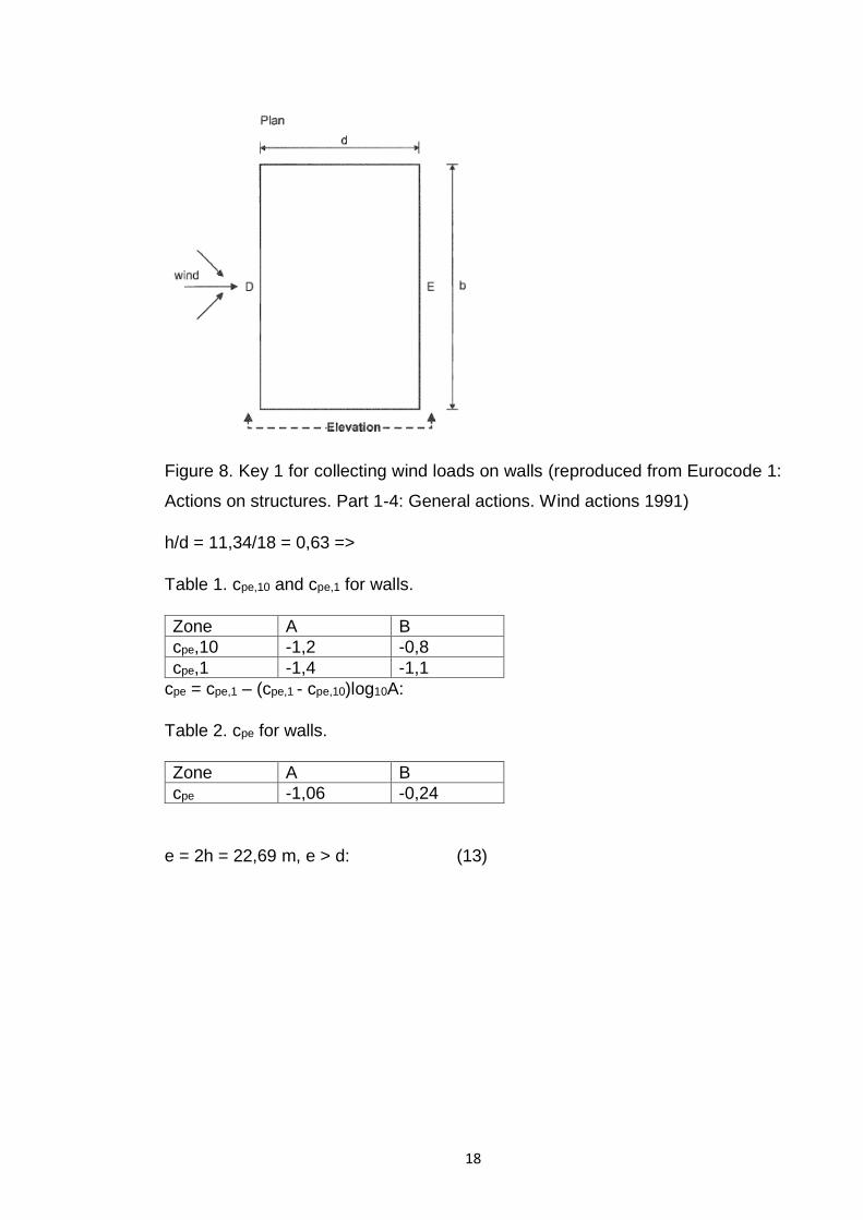
Figure 10. Reference height, ze, depending on hand b, and corresponding veloc-
ity pressure profile (reproduced from Eurocode 1: Actions on structures. Part 1-
4: General actions. Wind actions 1991)
h = 11,34 m < b = 18 m
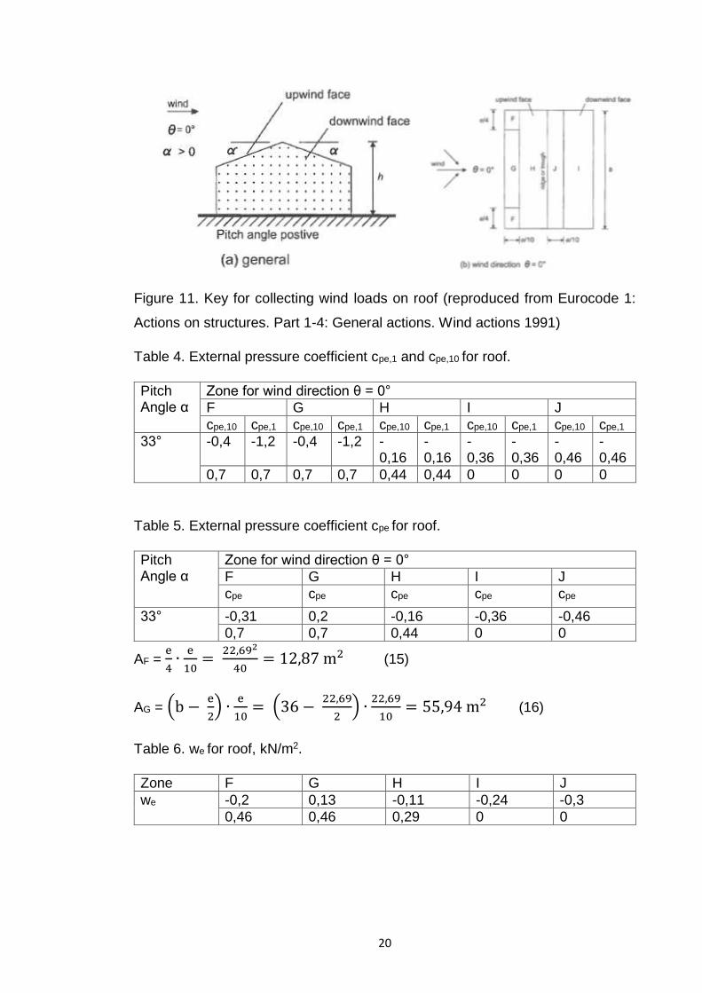
Wind loads on duopitch roof.
Wind direction θ = 0° is considered because the value of wind pressure in this
case is the highest.
Page 21
20
Figure 11. Key for collecting wind loads on roof (reproduced from Eurocode 1:
Actions on structures. Part 1-4: General actions. Wind actions 1991)
Table 4. External pressure coefficient cpe,1 and cpe,10 for roof.
Pitch Angle α
Zone for wind direction θ = 0°
F G H I J
cpe,10 cpe,1 cpe,10 cpe,1 cpe,10 cpe,1 cpe,10 cpe,1 cpe,10 cpe,1
33° -0,4 -1,2 -0,4 -1,2 -0,16
-0,16
-0,36
-0,36
-0,46
-0,46
0,7 0,7 0,7 0,7 0,44 0,44 0 0 0 0
Table 5. External pressure coefficient cpe for roof.
Pitch Angle α
Zone for wind direction θ = 0°
F G H I J
cpe cpe cpe cpe cpe
33° -0,31 0,2 -0,16 -0,36 -0,46
0,7 0,7 0,44 0 0
AF = e
4∙e
10=
22,692
40= 12,87m2 (15)
AG = (b −e
2) ∙
e
10=(36 −
22,69
2) ∙
22,69
10= 55,94m2 (16)
Table 6. we for roof, kN/m2.
Zone F G H I J
we -0,2 0,13 -0,11 -0,24 -0,3
0,46 0,46 0,29 0 0
Page 22
21
Table 7. Determination of wind actions
Parameter Value
peak velocity pressure qp basic wind velocity vb reference height ze terrain category characteristic peak velocity pressure qp
turbulence intensity Iv mean wind velocity vm orography coefficient co(z) roughness coefficient cr(z)
21 m/s 11,34 m II 0,66 kN/m2
0,18 21,63 m/s 1 1,03
Wind pressures, e.g. for cladding, fix-ings and structural parts external pressure coefficient cpe internal pressure coefficient cpi = 0,9 cpe, av net pressure coefficient cp,net external wind pressure: we=qp cpe internal wind pressure: wi=qp cpi
See Table 2,5 -0,28 - See Table 3,6 -0,18 kN/m2
Figure 12. Pressure on surfaces (reproduced from Eurocode 1: Actions on struc-
tures. Part 1-4: General actions. Wind actions 1991)
Page 23
22
4.4.3 Combination of actions
The following combinations of actions are considered in this case:
Ultimate limit state
𝐸𝑑 = 𝐸(𝛾𝐺𝐺 + 𝛾𝑄,𝑆𝑄𝑆 + 𝜓0,𝑊𝛾𝑄,𝑊𝑄𝑊) (17)
ψ0,W = 0,6, , γG = 1,1, γQ,S = γQ,W = 1,15
Serviceability limit state
𝐸𝑑 = 𝐸(𝐺 + 𝜓1,𝑆𝑄𝑆 + 𝜓2,𝑊𝛾𝑄,𝑊𝑄𝑊) (18)
ψ1,S = 0,4, ψ2,W = 0
Where:
E – effect of actions
Ed – design value of effect of action
G – permanent actions
Gd – design value of a permanent action
Qs – variable snow action
Qw – variable wind action
Calculations
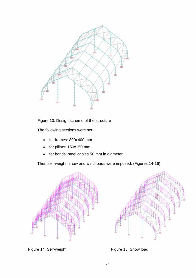
Further calculations were made in SCAD soft. Each element of the structure was
divided on finite elements of 1 meter. Border conditions were set by bearings
(Figure 13).
Page 24
23
Figure 13. Design scheme of the structure
The following sections were set:
for frames: 800x400 mm
for pillars: 150x150 mm
for bonds: steel cables 50 mm in diameter
Then self-weight, snow and wind loads were imposed. (Figures 14-16)
Figure 14. Self-weight
Figure 15. Snow load
Page 25
24
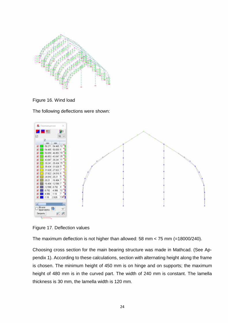
Figure 16. Wind load
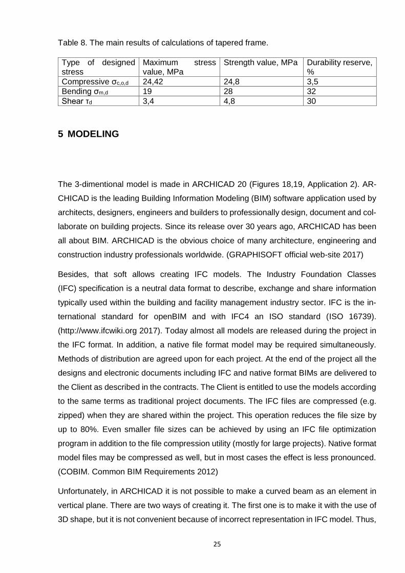
The following deflections were shown:
Figure 17. Deflection values
The maximum deflection is not higher than allowed: 58 mm < 75 mm (=18000/240).
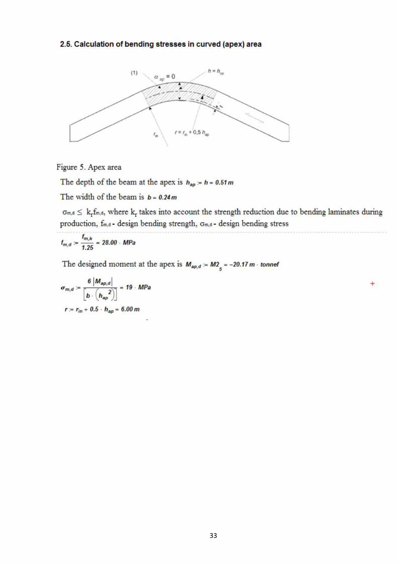
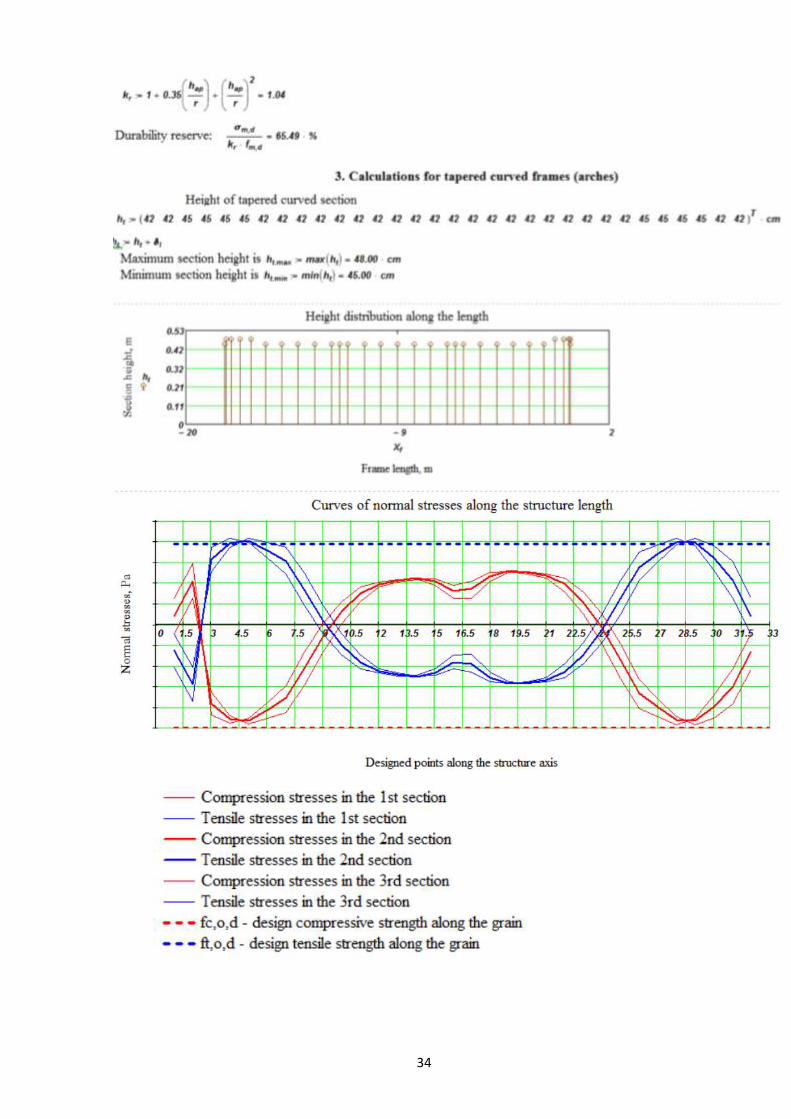
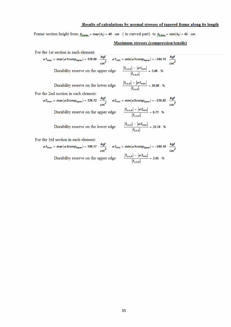
Choosing cross section for the main bearing structure was made in Mathcad. (See Ap-
pendix 1). According to these calculations, section with alternating height along the frame
is chosen. The minimum height of 450 mm is on hinge and on supports; the maximum
height of 480 mm is in the curved part. The width of 240 mm is constant. The lamella
thickness is 30 mm, the lamella width is 120 mm.
Page 26
25
Table 8. The main results of calculations of tapered frame.
Type of designed stress
Maximum stress value, MPa
Strength value, MPa Durability reserve, %
Compressive σc,o,d 24,42 24,8 3,5
Bending σm,d 19 28 32
Shear τd 3,4 4,8 30
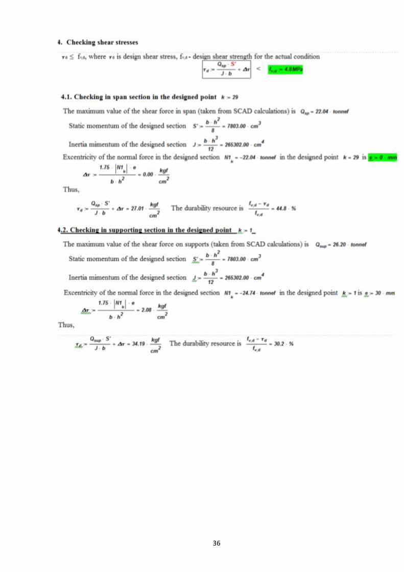
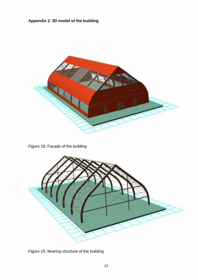
5 MODELING
The 3-dimentional model is made in ARCHICAD 20 (Figures 18,19, Application 2). AR-
CHICAD is the leading Building Information Modeling (BIM) software application used by
architects, designers, engineers and builders to professionally design, document and col-
laborate on building projects. Since its release over 30 years ago, ARCHICAD has been
all about BIM. ARCHICAD is the obvious choice of many architecture, engineering and
construction industry professionals worldwide. (GRAPHISOFT official web-site 2017)
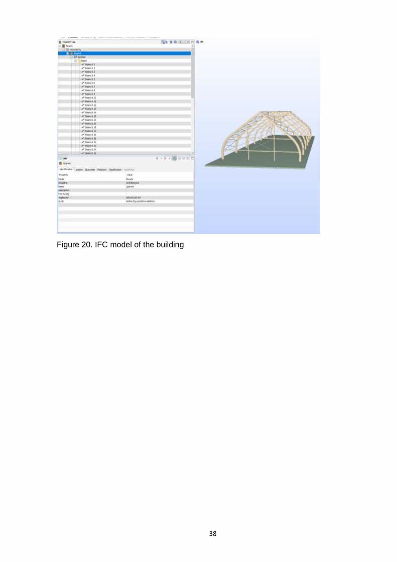
Besides, that soft allows creating IFC models. The Industry Foundation Classes
(IFC) specification is a neutral data format to describe, exchange and share information
typically used within the building and facility management industry sector. IFC is the in-
ternational standard for openBIM and with IFC4 an ISO standard (ISO 16739).
(http://www.ifcwiki.org 2017). Today almost all models are released during the project in
the IFC format. In addition, a native file format model may be required simultaneously.
Methods of distribution are agreed upon for each project. At the end of the project all the
designs and electronic documents including IFC and native format BIMs are delivered to
the Client as described in the contracts. The Client is entitled to use the models according
to the same terms as traditional project documents. The IFC files are compressed (e.g.
zipped) when they are shared within the project. This operation reduces the file size by
up to 80%. Even smaller file sizes can be achieved by using an IFC file optimization
program in addition to the file compression utility (mostly for large projects). Native format
model files may be compressed as well, but in most cases the effect is less pronounced.
(COBIM. Common BIM Requirements 2012)
Unfortunately, in ARCHICAD it is not possible to make a curved beam as an element in
vertical plane. There are two ways of creating it. The first one is to make it with the use of
3D shape, but it is not convenient because of incorrect representation in IFC model. Thus,
Page 27
26
in this work the second way is chosen: the whole structure is made with redirection of
planes (i.e. skates are created with the use of column tool, pillars and vertically oriented
beams are created with the use of beam tool). The chosen way allows reading IFC model
in the most correct way. (Figure 20, Appendix 2)
6 CONCLUSIONS
Nowadays timber structures are becoming more and more popular, because of lots of
advantages. Modern timber buildings have great variability. Combinations of different ma-
terials, such as glass, timber and steel look appealing. Moreover, it is easy to erect these
structures, because most of the assembling elements are prefabricated.
This study was released by using modern calculation and designing methods: all manual
calculations were reduced to minimum. As the main calculation and designing programs
the following softwares were chosen:
- SCAD software, which helped with determining stress values and deflections from
different combinations of actions, scheme of deformed structure;
- Mathcad software, which significantly allowed to reduce designing time (choosing
cross-section of the main bearing structure) and excluded the possibility of arith-
metical mistakes.
Besides, 3D models of the designed structure were created, according to the results of
calculations. This part of work was made in ARCHICAD soft. 3D modeling makes the
understanding of the structure easier and allows to show all elements from any suitable
angle.
The most significant result of this work is the Mathcad program for choosing cross section
of the three-pinned glued-laminated frame, which can be used for further calculations of
different structures with this kind of designed scheme.
Page 28
27
REFERENCES
1. Educational Materials for Designing and Testing of Timber Structures – TEMTIS. Handbook 1 – Timber structures. 2008. Leonardo da Vinci Pilot Project. 243 p.
2. Educational Materials for Designing and Testing of Timber Structures – TEMTIS. Handbook 2 – Designing of timber structures according to EN 5. 2008. Leonardo da Vinci Pilot Project. 138 p.
3. Gross H. 2001. Nordic Glulam Handbook. Svenskt Limitra AB, Stockholm. 360 p. 4. Finland National Annex to Standard SFS-EN 1995-1-1 Eurocode 5: Design of timber
structures. Part 1-1: Common rules and rules for buildings. 5. Finland National Annex to Standard SFS-EN 1991-1-3 Eurocode 1: Actions on struc-
tures. Part 1-3: General actions. Snow loads. 6. Finland National Annex to Standard SFS-EN 1991-1-3 Eurocode 1: Actions on struc-
tures. Part 1-4: General actions. Wind actions. 7. Setra official web-site. http://www.setragroup.com/en/glulam. Assessed on 19 March
2017. 8. SFS-EN 1991-1-3 Eurocode 1: Actions on structures. Part 1-4: General actions.
Wind actions. 9. SFS-EN 1991-1-3 Eurocode 1: Actions on structures. Part 1-3: General actions.
Snow loads. 10. SFS-EN 1995-1-1 Eurocode 5: Design of timber structures. Part 1-1: Common rules
and rules for buildings. 11. SCAD official web-site. http://scadsoft.com/en. Assessed on 20 March 2017. 12. GRAPHISOFT official web-site. http://www.graphisoft.com/archicad. Assessed on 20
March 2017. 13. http://www.ifcwiki.org. Assessed on 20 March 2017. 14. COBIM. Common BIM Requirements 2012. Series 1. General part. Version 1.0
03/27/2012. Parties to the © COBIM project. 22 p.
Page 29
28
APPENDICES
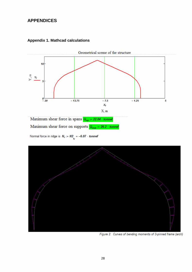
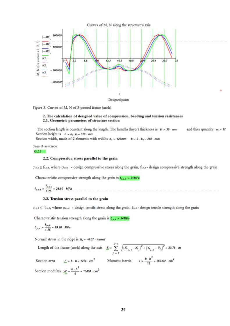
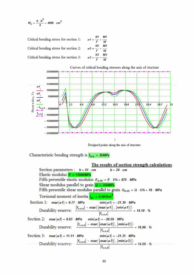
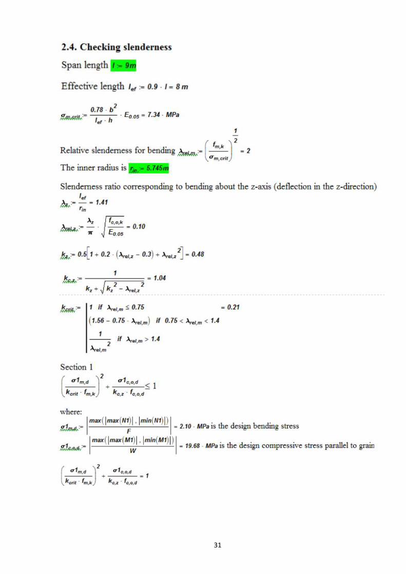
Appendix 1. Mathcad calculations
Page 38
37
Appendix 2. 3D model of the building
Figure 18. Facade of the building
Figure 19. Bearing structure of the building
Page 39
38
Figure 20. IFC model of the building