National Comfort Products 539 Dunksferry Road • Bensalem, PA 19020 • (215) 244-1400 • 1-800-523-7138 • Fax: (267) 638-1674 Installation & Maintenance Instruction Manual-Splits 12/30/14 Prepared Exclusively for Architects & Engineers ® ® SERIES 1000 26 1/4” w x 28 5/8” h SERIES 3000 24 1/8” w x 32” h SERIES 4000 30” w x 23” h THRU-THE-WALL CONDENSING UNITS Installation / Instruction Manual Thru-the-Wall Cooling Comfort
Transcript
National Comfort Products539 Dunksferry Road • Bensalem, PA 19020 • (215) 244-1400 • 1-800-523-7138 • Fax: (267) 638-1674
3. DESCRIPTIONOur condensing units are designed for the multi-family industry. The thru-the-wall operation saves money and time with simple easy installation. No long refrigerant or electrical runs, no ground clutter, no theft or vandalism, no roof penetrations and the unit can be easily serviced from indoors.
MODELS – Offering a Standard Model and a Deluxe New Yorker Model available in 3 series. Standard Models – Three different capacities 1.5 to 2.5 tons.
Deluxe New Yorker Models – Three different capacities 1.5 to 2.5 tons. Additional features (interior cabinet insulation, compressor crankcase heater, compressor hard start kit, solid state condenser fan motor speed control, high and low pressure switches, compressor
anti cycle time delay, condenser fan pre start timer, spring isolators for compressor, suction line vibration absorber.
MEA# – No longer needed in New York.
SERIES – 1000, 3000 & 4000 all offer different outside dimensions for multiple wall openings.
1000 Series – 26 1/4” x 28 5/8” x 18 1/2”3000 Series – 24 1/8” x 32” x 18 1/2”4000 Series – 30” x 23” x 18 1/2” (depth 22 1/2” on 2 & 2 1/2” ton units)
MATERIAL – Cabinet to be constructed of Pre-Painted Galvanized Steel. Indoor and outdoor coils shall be fabricated of raised lanced aluminum fins mechanically bonded to seamless rifled copper tubes.
COLOR – Tan
VOLTAGE – Units come factory wired for 208-230V/1P/60HZ with a low voltage circuit rated for a 24V/60HZ Class 2 transformer 40VA Minimum. The operating voltage of the unit is from 197 to 253 volts. (Single pole contactor used.)
Specification
FEATURES:
COMPATIBILITY – Units are compatible with most brands of “indoor” units.
CABINET– Heavy duty pre-painted cabinet (22 gauge metal).
EASY ACCESS – Units are easily serviced from inside. Control box and condenser fan are easily accessible.
SERVICE VALVES – Brass service valves with the ability to check operating pressures with service door reattached. 4. TECHNICAL DATA LIMITATIONS – All installations should factor a proper building heat gain, along with appropriate duct sizing and electrical supply wiring to be figured by a professional engineer familiar with local and national codes.
STANDARDS – AHRI Rated, AHRI Standard 210/240-2008 for Unitary Air-Conditioning and Air-Source Heat Pump Equipment. UL 1995 Listed for Safety.
Sound Data – Outdoor: (79.8 dba)Standard, AHRI 270-2008
Indoor: Without Indoor Cover (70.4 dba)Standard, AHRI 350-2008 Indoor: With Indoor Cover (68.3 dba)Standard, AHRI 350-2008
ENVIRONMENTAL – Environmentally friendly refrigerant HCFC R410A Intertek Safety Report Number – ETL Testing Laboratories Inc.Inspection, Test and Evaluation Report no. 513536
5. INSTALL All units have an optional highly recommended, wall sleeve for a clean finish and future service accessibility. Provide clearances minimal of 30” in front of access panels for service and proper distances from all outside utilities in accordance with all local and national codes. A minimum vertical clearance of 48” between units should be maintained to minimize recirculation of condenser air.
6. SALES National Comfort Products are dealt through a variety of wholesalers. Contact the factory to help locate a nearby distributor for price and availability.
7. WARRANTY 1 year warranty of all parts and 5 year warranty of the compressor. 90 days labor warranty. 8. SERVICEThe unit can be easily serviced from indoors and should be properly maintained in accordance of the manufacture instructions. All standard maintenance instructions are within the installation and users guides.
9. TECHNICAL SUPPORTFactory technical assistance is available to help with any concerns or situations regarding National Comfort Products.
Installation/Instruction Manual for Architects & Engineers
A Division of National Refrigeration & Air Conditioning Products, Inc. 539 Dunksferry Road • Bensalem, PA 19020 • (215) 244-1400 • 1-800-523-7138 • Fax: (215) 639-1674
SUBMITTAL PACKAGE R-410A SPLIT-SYSTEM CONDENSING UNITS
14 min. AWG wire 12 min. AWG wire 12 min. AWG wire 14 min. AWG wire 12 min. AWG wire 12 min. AWG wire 14 min. AWG wire 12 min. AWG wire 12 min. AWG wire
Bryant, Carrier, Day & Night, Dunham-Bush, Lennox, Magic Chef, Meyer, Payne, First Co., U.S. A/C (BB)
Carrier, Fedders, Dunham-Bush, Lennox, Magic Chef, Meyer, Rheem, First Co., U.S. A/C (AB)
Dunham-Bush, Hydro-Therm Space Pack, Lennox, Luxaire York, First Co., U.S. A/C (CB)
NCPE1000 NCPE 3000 NCPE4000
Note: All specifications are subject to change without notice. * Condensing units are compatible with most manufacturers of indoor air handlers and coils. * *Dimensions including screw heads on both sides of the cabinet.
If the heater is being installed at an elevation above 2000 ft. (610M), the input rate will have to be derated. This is done by adjusting the valve outlet pressure. In addition, if the heater is being installed at an altitude above 6000 ft. (1830M), the pressure switch will have to be changed. Adjusting the valve outlet pressure is done after the heater is in operation; follow the instructions below. If the pressure switch needs changed, do that before the heater is operated (see Figure 1).
3
High Altitude Operation
Figure 1 - Pressure Switch
Heat Section Burner/Control Compartment (NOTE: Unit side panel is removed for clarity; side panel is not removable. Access to the burner/control compartment is through the small rear access panel as illustrated in Figure 2.)
High Limit Vent Motor
Pressure Switch
High Altitude Combustion Air Pressure SwitchSIZE P/N DESCRIPTION
ALL 14208325 Set to break on pressure increase @ -0.5” w.c.
Instructions for Changing Pressure Switch
Open the burner/control compartment access panel. 1. Locate the pressure switch.Mark and disconnect the two wires attached to the 2. pressure switch.Disconnect the flow sensing tubing from the pressure 3. switch.Locate the two screws holding the switch mounting 4. bracket. Remove the screws (save screws) and the pressure switch.Install the high altitude pressure switch. Attach the 5. sensing tube and wires. Replace access panel.
Derating by Valve Outlet Pressure Adjustment for High Altitude Operation
Instructions
NOTE: This adjustment can only be done after the heater is in operation. It is included in the startup procedures.
Determine the required valve outlet pressure for the 1. elevation where the heater will be operating. If unsure of the elevation, contact the local gas supplier.
VALVE OUTLET PRESSURE SETTINGS BY ELEVATION
ALTITUDE NATURAL GAS (inches w.c.)
PROPANE GAS(inches w.c.)Feet Meters
0 - 2000 1 - 610 3.5 10.0
2001 - 3000 611 - 915 2.8 7.7
3001 - 4000 916 - 1220 2.5 7.1
4001 - 5000 1221 - 1525 2.3 6.4
5001 - 6000 1526 - 1830 2.1 5.8
6001 - 7000 1831 - 2135 1.9 5.2
7001 - 8000 2136 - 2440 1.7 4.6
8001 - 9000 2441 - 2745 1.5 4.1
With the manual valve positioned to prevent flow to the 2. main burner, connect a manometer to the 1/8” pipe outlet pressure tap in the valve. Use a water column manometer that is readable to the nearest tenth of an inch.
Remove the cap from the pressure adjusting screw and 3. adjust the valve outlet pressure to the pressure setting selected from the table. Cycle the main burner once or twice to properly seat the adjustment spring in the valve. Re-check the pressure. If necessary, re-adjust the pressure. When the pressure is correct, remove the manometer and replace the cap. Check for leaks at the pressure tap fitting.
With the heater operating determine that the inlet pressure 4. to the heater for natural gas is between 5 and 13.5 inches w.c., and for propane between 10 and 13.5 inches w.c. Take this reading as close as possible to the heater (heaters are equipped with gas valves that have an inlet pressure tap.) If the inlet is not within the specified range, the inlet pressure must be corrected and Steps 3 and 4 repeated.
Find the Valve Outlet Pressure Adjustment label in the 5. plastic bag that contained these instructions. Using a permanent marker, fill in the pressure setting. Adhere the label on the heater near the gas valve so that it is conspicuous to someone servicing the valve.
The Thru-the-Wall Condenser
AHRI / DOENational Comfort Products is rated thru AHRI Standard 210/240-2008 for Unitary Air-Conditioning and Air-Source Heat Pump Equipment, website: (http://www.ahridirectory.org/ahridirectory/pages/ac/defaultSearch.aspx) and recognized by the Department of Energy, website: (http://www.regulations.doe.gov/certification-data/CCMS-79222816513.html). All units are rated at 12 SEER.
Why Thru-The-WallUnits are easily serviced in any weather condition. They are less expensive to install and eliminate ground clutter. There is less risk of theft or vandalism, no roof penetrations, shorter line sets, and less refrigerant charge. They also offer the ability for separate electrical meter savings and have a better overall appearance. (See Architectural Grille Section on page 19)
sEriEs 1000 26 1/4” w x 28 5/8” h
sEriEs 3000 24 1/8” w x 32” h
sEriEs 4000 30” w x 23” h
6.
(You can also check our website for DOE & AHRI matched air handlers)
Installation/Instruction Manual for Architects & Engineers
If the heater is being installed at an elevation above 2000 ft. (610M), the input rate will have to be derated. This is done by adjusting the valve outlet pressure. In addition, if the heater is being installed at an altitude above 6000 ft. (1830M), the pressure switch will have to be changed. Adjusting the valve outlet pressure is done after the heater is in operation; follow the instructions below. If the pressure switch needs changed, do that before the heater is operated (see Figure 1).
3
High Altitude Operation
Figure 1 - Pressure Switch
Heat Section Burner/Control Compartment (NOTE: Unit side panel is removed for clarity; side panel is not removable. Access to the burner/control compartment is through the small rear access panel as illustrated in Figure 2.)
High Limit Vent Motor
Pressure Switch
High Altitude Combustion Air Pressure SwitchSIZE P/N DESCRIPTION
ALL 14208325 Set to break on pressure increase @ -0.5” w.c.
Instructions for Changing Pressure Switch
Open the burner/control compartment access panel. 1. Locate the pressure switch.Mark and disconnect the two wires attached to the 2. pressure switch.Disconnect the flow sensing tubing from the pressure 3. switch.Locate the two screws holding the switch mounting 4. bracket. Remove the screws (save screws) and the pressure switch.Install the high altitude pressure switch. Attach the 5. sensing tube and wires. Replace access panel.
Derating by Valve Outlet Pressure Adjustment for High Altitude Operation
Instructions
NOTE: This adjustment can only be done after the heater is in operation. It is included in the startup procedures.
Determine the required valve outlet pressure for the 1. elevation where the heater will be operating. If unsure of the elevation, contact the local gas supplier.
VALVE OUTLET PRESSURE SETTINGS BY ELEVATION
ALTITUDE NATURAL GAS (inches w.c.)
PROPANE GAS(inches w.c.)Feet Meters
0 - 2000 1 - 610 3.5 10.0
2001 - 3000 611 - 915 2.8 7.7
3001 - 4000 916 - 1220 2.5 7.1
4001 - 5000 1221 - 1525 2.3 6.4
5001 - 6000 1526 - 1830 2.1 5.8
6001 - 7000 1831 - 2135 1.9 5.2
7001 - 8000 2136 - 2440 1.7 4.6
8001 - 9000 2441 - 2745 1.5 4.1
With the manual valve positioned to prevent flow to the 2. main burner, connect a manometer to the 1/8” pipe outlet pressure tap in the valve. Use a water column manometer that is readable to the nearest tenth of an inch.
Remove the cap from the pressure adjusting screw and 3. adjust the valve outlet pressure to the pressure setting selected from the table. Cycle the main burner once or twice to properly seat the adjustment spring in the valve. Re-check the pressure. If necessary, re-adjust the pressure. When the pressure is correct, remove the manometer and replace the cap. Check for leaks at the pressure tap fitting.
With the heater operating determine that the inlet pressure 4. to the heater for natural gas is between 5 and 13.5 inches w.c., and for propane between 10 and 13.5 inches w.c. Take this reading as close as possible to the heater (heaters are equipped with gas valves that have an inlet pressure tap.) If the inlet is not within the specified range, the inlet pressure must be corrected and Steps 3 and 4 repeated.
Find the Valve Outlet Pressure Adjustment label in the 5. plastic bag that contained these instructions. Using a permanent marker, fill in the pressure setting. Adhere the label on the heater near the gas valve so that it is conspicuous to someone servicing the valve.
Locating the UnitClearance AwarenessThe unit must not be mounted in dead-end hallways or areas where there is no fresh outside air circulation. Cool fresh outside air must be provided for best operation. Units should not be located where hot exhausts from clothes dryer vents, kitchen vents, steam vents or where corrosive fumes could come in contact with the coil side of the unit.
Important: If one or more units is installed in vertical array a minimum of 48” is required and must be maintained to minimize recirculation of condenser exhaust air.
You cannot stack units
7.
Installation/Instruction Manual for Architects & Engineers
Minimum
48” Required
Between Units
“Vertical Array” Installation
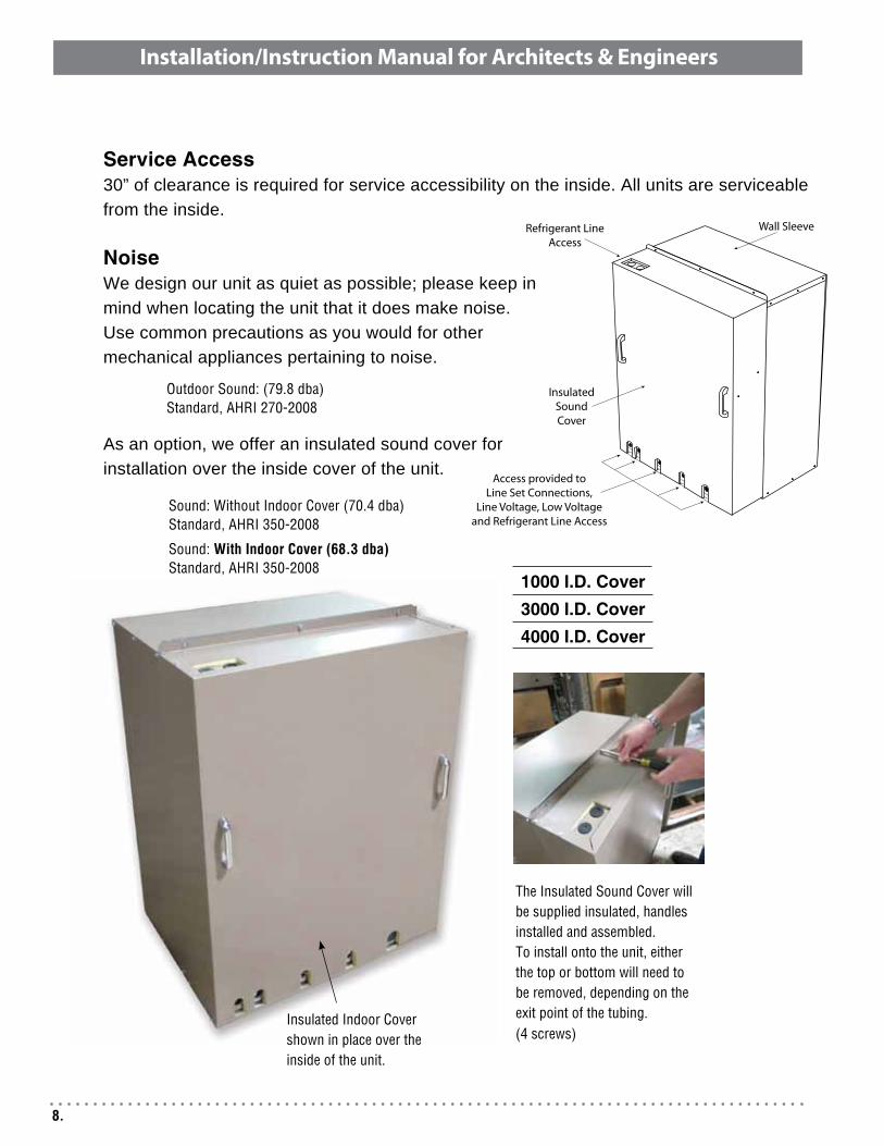
Service Access30” of clearance is required for service accessibility on the inside. All units are serviceable from the inside. NoiseWe design our unit as quiet as possible; please keep in mind when locating the unit that it does make noise. Use common precautions as you would for other mechanical appliances pertaining to noise.
As an option, we offer an insulated sound cover for installation over the inside cover of the unit.
insulated indoor Cover shown in place over the inside of the unit.
The insulated sound Cover will be supplied insulated, handles installed and assembled.To install onto the unit, either the top or bottom will need to be removed, depending on theexit point of the tubing.(4 screws)
1000 I.D. Cover3000 I.D. Cover4000 I.D. Cover
8.
Installation/Instruction Manual for Architects & Engineers
sound: Without indoor Cover (70.4 dba)standard, AHri 350-2008
sound: With indoor Cover (68.3 dba)standard, AHri 350-2008
Outdoor sound: (79.8 dba)standard, AHri 270-2008
Wall Sleeve
Insulated SoundCover
Refrigerant Line Access
Access provided to Line Set Connections,
Line Voltage, Low Voltage and Refrigerant Line Access
WallsWall SleeveAvailable for 1000, 3000 & 4000 Series Our wall sleeve must be field assembled and easily forms a box with mounting brackets, guides, and seals. It should be installed with a non-hardening caulk into the opening of the wall. The sleeve should be installed 3/4” past the exterior wall for proper weather sealing.
In different builds, the sleeve must be fastened to the supporting wall and not the finished wall.
1000-WSD-12H x W
295/8” x 267/8” (Rough in at: 301/8” x 273/8”)
3000-WSD-12H x W
33” x 247/8” (Rough in at: 331/2” x 253/8”)
4000-WSD-12*H x W
24” x 305/8” (Rough in at: 241/2” x 311/8”)
9.
Installation/Instruction Manual for Architects & Engineers
Wall Construction The wall sleeve is designed to support the unit but the wall itself must be adequate to support the unit. When this is an issue a support is needed at the base of the unit.
For wood frame walls the sleeve can be adequately fastened with lag screws into doubled two by six and should be pressed against only solid wood material. Vibration pads can be used in light weight framing designs. Must be adequate to support 280 lbs.
For masonry wall applications, a proper lintel should be installed to support the wall.
127/16”
⅜” Min.
Seal around Sleeve and outside wall
Seal around Sleeve and inside wall
Wall Sleeve
⅜” Min.
Flashing by others
Flashing by othersminimum. 3”
3 sides
10.
Installation/Instruction Manual for Architects & Engineers
Sealing of the Unit WaterThe wall opening across the top and bottom must be flashed. Bottom flashing to cover the full foot print of the unit and extend up 2” on 3 sides. All openings around the top, sides and bottom must be caulked and sealed. It is very important not to plug the weephole openings in the front section of the unit base pan... these are critical for drainage of moisture or rain. If a wall sleeve is used, caulk the spaces between the sleeve and the wall. Completely fill the clearance between the unit and the wall sleeve with a polyurethane foam sealant.
During periods of rain and wind the primary drainage path may not be adequate to handle the load. Secondary drainage precautions may also be required but not limited to the following: a. Seal flashing to unit b. Floor drain c. Additional field sealing of sheet metal joints d. Sealing of unused access opening
AirClearance to air inlets and outlets must be adequate to ensure no air flow obstructions or recirculation of condenser air flow.
Obstructed Air Flow
11.
Installation/Instruction Manual for Architects & Engineers
ElectricalHigh VoltageThe unit is factory wired for 208/230 Volts AC Single Phase 60 Hertz. The operating voltage is from 197 VAC to 253 VAC. A single pole contactor is used for connection.
Low VoltageThe unit is rated for a 24 Volt 60 Hertz Class 2 transformer with a 40 VA minimum to supply the low voltage to the contactor.
12.
Condensing Unit Control Box
Installation/Instruction Manual for Architects & Engineers
RefrigerationEvaporatorAll units are approved with indoor evaporator coils utilizing a Thermal Expansion Valve (TXV). Self-equalizing components are required to reduce compressor starting problems. If self-equalizing components are not used, field installed hard start kits will be required. Units are compatible with most brands of “indoor” units. (Check our website for DOE & AHRI matched air handlers)
Line setWhen replacing R22 units it is highly recommend that the line sets be replaced. If that option is not feasible it is necessary to flush the line set with a commercial flushing agent. The unit has internally mounted service valves. Field tubing may be routed through the locations provided in either the top or rear flange. Care should be taken not to block access to internal components. Seal all unused knockouts and use provided gaskets for liquid and suction lines.
All units are designed set for 3/8” Liquid Line and 3/4” Vapor Line. When line set may exceed 50’ please consult the factory.
When installing the condenser below the evaporator, the suction line must be trapped with an inverted trap the height of the evaporator coil.
A minimum of 1/2” foam rubber insulation is required for the suction line.
All field connections should be brazed while purging system with Dry Nitrogen. System should be pressure tested at approximately. 100 psi dry nitrogen and then evacuated to 300 microns (held for 10 minutes) before opening service valves. Be sure that all service valves are protected during brazing.
13.
Installation/Instruction Manual for Architects & Engineers
Service
For servicing of the unit it is imperative that 30” of clearance be available in front of the unit access panel. All electrical components are inside an easy access control box to aid in checking the contactor and capacitor electrical connections. The condenser fan motor is easily accessible for inspection of the bearings.
To clean the condenser coil it is recommended to use high pressure nitrogen from the interior with a non-rinse, non-acidic coil cleaner. Keep building exterior material in consideration when choosing cleaning products. If the coil is accessible from the outside, the coil can be brushed clean with care to not damage the aluminum fins.
14.
Installation/Instruction Manual for Architects & Engineers
These units must be installed in accordance with local building codes. In the absence of local codes, in the United States, the unit must be installed in accordance with the National Fuel Gas Code (latest edition). A Canadian installation must be in accor-dance with the CAN/CGA-B149.1 and B149.2 Installation Code for Gas Burning Appliances and Equipment. These codes are available from CSA Information Services, 1-800-463-6727. Local authorities having jurisdiction should be considered before installation is made to verify local codes and installation procedure requirements.
HEAT MODULE P/N 14208309 14208308 14208303
INPUT BTUH
38,000 51,000 64,000
OUTPUT BTUH
30,400 40,800 51,200
MAXIMUM EXTERNAL STATIC
PRESSURE(INCHES W.C.)
.5 .5 .5
DISCHARGE AIR TEMPERATURE
RISE RANGE(°F)
40 to 70 40 to 70 55 to 85
BLOWER SPEED SETTING
Low Medium High
To ensure safe operation and long life of the heat exchanger, the maximum static pressure and/or maximum temperature rise must not be exceeded. Operation of the heater at condi-tions that exceed the heater’s specifications will void the heat exchanger warranty.
MODEL SIZE 38 51 64
ORIFICE SIZE N.G.
31 28 22
ORIFICE SIZE LP
49 2.1 mm 41
NOMINAL TEMPERATURE
RISE (°F) 55 55 65
ALLOWABLE AIR TEMPERATURE
RANGE140 - 170 140 - 170 135 - 165
CO2 % - ACCEPTABLE
RANGE4.2 to 5.2 4.8 to 5.8 4.5 to 5.5
CO1
AIR FREE - PPM0 - 200 0 - 200 0 - 200
SENSING COLD
1.05 +/-.1 1.05 +/-.1 1.05 +/-.1
PRESSURE HOT .8 +/-.05 8 +/-.05 8 +/-.05
EFFICIENCY(% - RANGE)
81.5 - 82.5 81.5 - 82.5 80.1 - 81.1
STACK TEMPERATURE
(°F)245 - 300 245 - 300 270 - 330
2
WARNING: IF THE INFORMATION IN THIS MANUAL IS NOT FOLLOWED EXACTLY, A FIRE OR EXPLOSION MAY RESULT CAUSING PROPERTY DAMAGE, PERSONAL INJURY OR LOSS OF LIFE.
WHAT TO DO IF YOU SMELL GAS:
Do • NOT try to light any appliance.Do • NOT touch any electrical switch; do not use any phone in your building.Immediately call your gas supplier from a neighbor’s •phone. Follow the gas supplier’s instructions. If you cannot reach your gas supplier, call your fire •department.
Do NOT store or use combustible materials, gasoline or other flammable vapors and liquids in the vicinity of this or any other appliance.
WARNING: IMPROPER INSTALLATION, ADJUST-MENT, ALTERATION, SERVICE, OR MAINTENANCE CAN CAUSE PROPERTY DAMAGE, INJURY, OR DEATH. READ THE INSTALLATION, OPERATION AND MAINTENANCE INSTRUCTIONS THOROUGHLY BEFORE INSTALLING OR SERVICING THIS EQUIP-MENT.
WARNING: GAS-FIRED APPLIANCES ARE NOT DE-SIGNED FOR USE IN HAZARDOUS ATMOSPHERES CONTAINING FLAMMABLE VAPORS OR COMBUS-TIBLE DUST, IN ATMOSPHERES CONTAINING CHLO-RINATED OR HALOGENATED HYDROCARBONS, OR IN APPLICATIONS WITH AIRBORNE SILICONE SUB-STANCES. SEE HAZARD LEVELS BELOW.
WARNING: SHOULD OVERHEATING OCCUR, OR THE GAS SUPPLY FAIL TO SHUT OFF, SHUT OFF THE MANUAL GAS VALVE TO THE APPLIANCE BEFORE SHUTTING OFF THE ELECTRICAL SUPPLY.
WARNING: DO NOT USE THIS APPLIANCE IF ANY PART HAS BEEN UNDER WATER. IMMEDIATELY CALL A QUALIFIED SERVICE TECHNICIAN TO IN-SPECT THE APPLIANCE AND REPLACE ANY GAS CONTROL THAT HAS BEEN UNDER WATER.
HAZARD INTENSITY LEVELS
DANGER: FAILURE TO COMPLY MAY RESULT 1. IN SEVERE PERSONAL INJURY OR DEATH AND/OR PROPERTY DAMAGE.WARNING: FAILURE TO COMPLY COULD RESULT 2. IN SEVERE PERSONAL INJURY OR DEATH AND/OR PROPERTY DAMAGE.CAUTION: FAILURE TO COMPLY COULD 3. RESULT IN MINOR PERSONAL INJURY AND/OR PROPERTY DAMAGE.
For Your Safety
Installation Codes
Heating Specifications
15.
Installation/Instruction Manual for Architects & Engineers
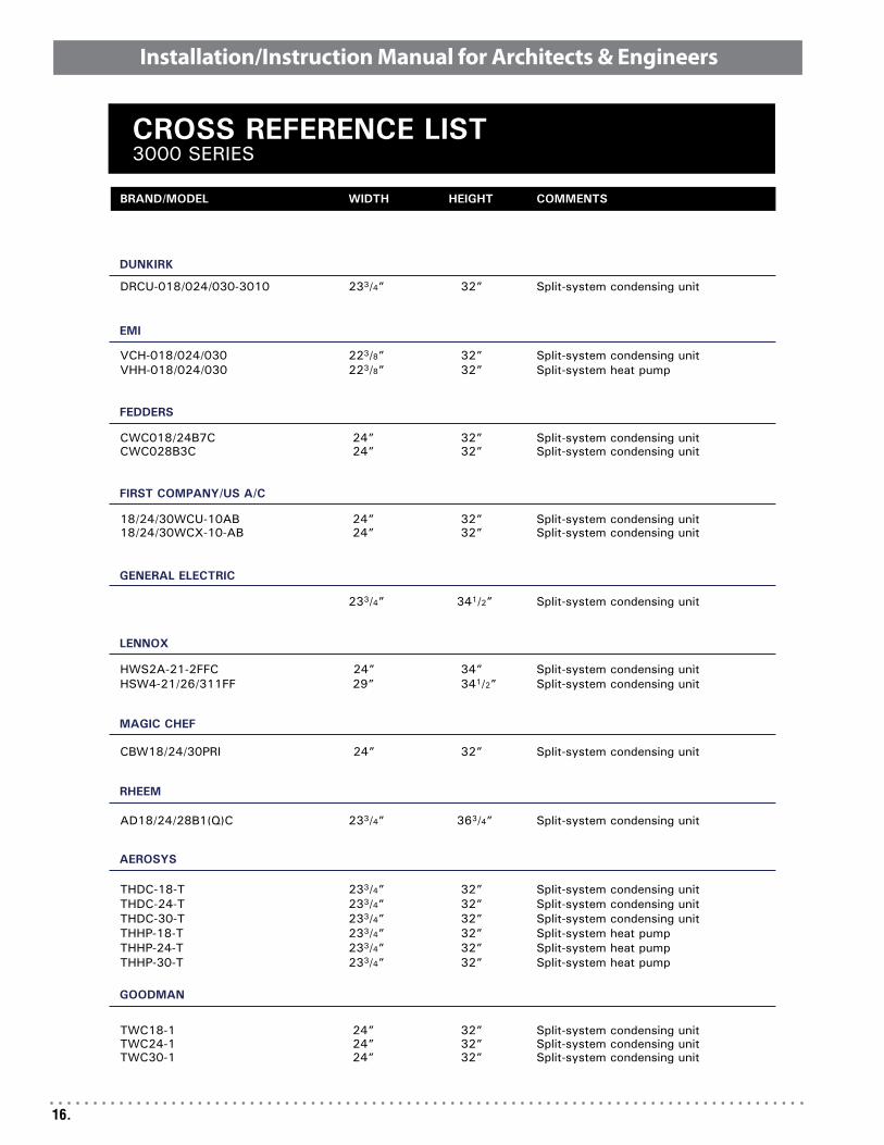
Cross Reference & Replacement
(3000 & 4000 Series reference next two pages...)
16.
Installation/Instruction Manual for Architects & Engineers
DUNKIRK
GENERAL ELECTRIC
LENNOX
EMI
FEDDERS
FIRST COMPANY/US A/C
MAGIC CHEF
RHEEM
AEROSYS
GOODMAN
BRAND/MODEL WIDTH HEIGHT COMMENTS
DRCU-018/024/030-3010 233/4” 32” Split-system condensing unit
These units must be installed in accordance with local building codes. In the absence of local codes, in the United States, the unit must be installed in accordance with the National Fuel Gas Code (latest edition). A Canadian installation must be in accor-dance with the CAN/CGA-B149.1 and B149.2 Installation Code for Gas Burning Appliances and Equipment. These codes are available from CSA Information Services, 1-800-463-6727. Local authorities having jurisdiction should be considered before installation is made to verify local codes and installation procedure requirements.
HEAT MODULE P/N 14208309 14208308 14208303
INPUT BTUH
38,000 51,000 64,000
OUTPUT BTUH
30,400 40,800 51,200
MAXIMUM EXTERNAL STATIC
PRESSURE(INCHES W.C.)
.5 .5 .5
DISCHARGE AIR TEMPERATURE
RISE RANGE(°F)
40 to 70 40 to 70 55 to 85
BLOWER SPEED SETTING
Low Medium High
To ensure safe operation and long life of the heat exchanger, the maximum static pressure and/or maximum temperature rise must not be exceeded. Operation of the heater at condi-tions that exceed the heater’s specifications will void the heat exchanger warranty.
MODEL SIZE 38 51 64
ORIFICE SIZE N.G.
31 28 22
ORIFICE SIZE LP
49 2.1 mm 41
NOMINAL TEMPERATURE
RISE (°F) 55 55 65
ALLOWABLE AIR TEMPERATURE
RANGE140 - 170 140 - 170 135 - 165
CO2 % - ACCEPTABLE
RANGE4.2 to 5.2 4.8 to 5.8 4.5 to 5.5
CO1
AIR FREE - PPM0 - 200 0 - 200 0 - 200
SENSING COLD
1.05 +/-.1 1.05 +/-.1 1.05 +/-.1
PRESSURE HOT .8 +/-.05 8 +/-.05 8 +/-.05
EFFICIENCY(% - RANGE)
81.5 - 82.5 81.5 - 82.5 80.1 - 81.1
STACK TEMPERATURE
(°F)245 - 300 245 - 300 270 - 330
2
WARNING: IF THE INFORMATION IN THIS MANUAL IS NOT FOLLOWED EXACTLY, A FIRE OR EXPLOSION MAY RESULT CAUSING PROPERTY DAMAGE, PERSONAL INJURY OR LOSS OF LIFE.
WHAT TO DO IF YOU SMELL GAS:
Do • NOT try to light any appliance.Do • NOT touch any electrical switch; do not use any phone in your building.Immediately call your gas supplier from a neighbor’s •phone. Follow the gas supplier’s instructions. If you cannot reach your gas supplier, call your fire •department.
Do NOT store or use combustible materials, gasoline or other flammable vapors and liquids in the vicinity of this or any other appliance.
WARNING: IMPROPER INSTALLATION, ADJUST-MENT, ALTERATION, SERVICE, OR MAINTENANCE CAN CAUSE PROPERTY DAMAGE, INJURY, OR DEATH. READ THE INSTALLATION, OPERATION AND MAINTENANCE INSTRUCTIONS THOROUGHLY BEFORE INSTALLING OR SERVICING THIS EQUIP-MENT.
WARNING: GAS-FIRED APPLIANCES ARE NOT DE-SIGNED FOR USE IN HAZARDOUS ATMOSPHERES CONTAINING FLAMMABLE VAPORS OR COMBUS-TIBLE DUST, IN ATMOSPHERES CONTAINING CHLO-RINATED OR HALOGENATED HYDROCARBONS, OR IN APPLICATIONS WITH AIRBORNE SILICONE SUB-STANCES. SEE HAZARD LEVELS BELOW.
WARNING: SHOULD OVERHEATING OCCUR, OR THE GAS SUPPLY FAIL TO SHUT OFF, SHUT OFF THE MANUAL GAS VALVE TO THE APPLIANCE BEFORE SHUTTING OFF THE ELECTRICAL SUPPLY.
WARNING: DO NOT USE THIS APPLIANCE IF ANY PART HAS BEEN UNDER WATER. IMMEDIATELY CALL A QUALIFIED SERVICE TECHNICIAN TO IN-SPECT THE APPLIANCE AND REPLACE ANY GAS CONTROL THAT HAS BEEN UNDER WATER.
HAZARD INTENSITY LEVELS
DANGER: FAILURE TO COMPLY MAY RESULT 1. IN SEVERE PERSONAL INJURY OR DEATH AND/OR PROPERTY DAMAGE.WARNING: FAILURE TO COMPLY COULD RESULT 2. IN SEVERE PERSONAL INJURY OR DEATH AND/OR PROPERTY DAMAGE.CAUTION: FAILURE TO COMPLY COULD 3. RESULT IN MINOR PERSONAL INJURY AND/OR PROPERTY DAMAGE.
Installation/Instruction Manual for Architects & Engineers
18.
Installation/Instruction Manual for Architects & Engineers
Cross Reference & ReplacementOur (3) series can replace several obsolete model manufactured by alternate companies. We offer a detailed cross reference guide (the three previous pages) to aid in selecting the proper replacement condenser. We also offer filler and escutcheon plates for jobs with dimensional differences.
CADD rendering shown
Acutal install
Architectural GrillesAll units come shipped with a wire grille in front of the condenser coil.
We offer a line of Architectural Grilles for all 3 series that can come with a standard aluminum anodized finish or a baked enamel custom painted finish.
Standard Colors
LB - Lite Bronze MB - Medium Bronze DB - Dark Bronze
EW - Off White GW - Gloss White WS - White Stone
BR1 - Brick Red 1 BR3 - Brick Red 3 BR5 - Brick 5
SLG - Slate Gray MBL - Medium Blue MGN - Medium Green
§ Can be color matched to any color, consult factory.
Installation/Instruction Manual for Architects & Engineers
Warranty
LIMITED EXTENDED PROTECTION WARRANTYFOR
NATIONAL COMFORT PRODUCTS (NCP) BENSALEM, PASPLIT-SYSTEM CONDENSING UNITS
This NCP product is warranted to be free from all manufacturing defects, material or workmanship, for a period of one year from the date of installation (receipt required), whether or not actual use begins on this date, or one year from the date of manufacture if the date of installation cannot be verified. Immediate notice to NCP will (A) provide a new or remanufactured part to replace the defective part, without charge for the part itself, or (B) provide a replacement unit.
National Comfort Products will not be responsible for: local transportation, removing, related service, labor, diagnosis calls, refrigerant, costs incurred for returning defective parts, damage or repairs required due to faulty installation or improper application by others, damage as a result of fire, wind, floods, lightning, accidents, or corrosive atmosphere.
EXTENDED 2ND THRU 5TH YEAR COMPRESSOR WARRANTYIf the compressor should fail because of a manufacturing defect, is in the original installation, has been operated under normal conditions, and is in the 2nd to 5th year following the above determined date, NCP will provide, at its option, a new or remanufactured replacement compressor.
Replacement parts are warranted for the remainder of the original product warranty, or for 90 days, whichever is longer. NCP may require that defective parts be returned to verify and identify the cause of the defect.
LIMITATION OF WARRANTIES — ALL IMPLIED WARRANTIES (INCLUDING IMPLIED WARRANTIES OF MERCHANTABILITY) ARE HEREBY LIMITED IN DURATION TO THE PERIOD FOR WHICH EACH LIMITED WARRANTY IS GIVEN. SOME STATES DO NOT ALLOW LIMITATIONS ON HOW LONG AN IMPLIED WARRANTY LASTS, SO THE ABOVE LIMITATIONS MAY NOT APPLY TO YOU. THE EXPRESSED WARRANTIES MADE IN THIS WARRANTY ARE EXCLUSIVE AND MAY NOT BE ALTERED, ENLARGED, OR CHANGED BY ANY DISTRIBUTOR, DEALER, OR OTHER PERSON WHATSOEVER. MATERIAL IS INSPECTED AT THE FACTORY AND RELEASED TO TRANSPORTATION AGENCY IN GOOD CONDITION. WHEN RECEIVED, VISUAL INSPECTION MUST BE MADE IMMEDIATELY. APPARENT SHIPPING DAMAGE SHOULD BE NOTED ON THE DELIVERY RE-CEIPT AND THE MATERIAL INSPECTED IN THE PRESENCE OF THE CARRIER’S REPRESENTATIVE. IF DAMAGE IS FOUND A CLAIM MUST BE FILED WITH THE CARRIER IMMEDIATELY.
FREIGHT DAMAGE IS NOT COVERED UNDER THIS WARRANTY.
WARNING: NO WARRANTY ON NEW UNITS INSTALLED BEHIND BRICK FACADES. IN YEARS PAST, IT WAS COMMON PRACTICE TO ADD A BRICK PATTERN FACADE (PIGEON HOLES) IN FRONT OF THE THRU-THE-WALL UNIT TO CHANGE THE EXTERIOR APPEARANCE OF THE BUILDING. ALL OBSTACLES ADDED TO IMPEDE AIR FLOW OF THE CONDENSING UNIT WILL DECREASE PERFORMANCE AND CAUSE PREMATURE EQUIPMENT FAILURE AND VOID ALL WARRANTIES. CONSULT FACTORY WITH ANY QUESTIONS.
This warranty gives you specific legal rights. You may also have rights which vary from state to state.
NATIONAL COMFORT PRODUCTS, BENSALEM, PENNSYLVANIA
NOTE: All warranty parts and paper work must be submitted no later than 60 days after failure. Warranty requests submitted after 60 days of failure will not be processed.
*All prices subject to change without notice.
WARRANTY INFORMATION CONDENSING UNITS AND HEAT PUMPS
20.
Installation/Instruction Manual for Architects & Engineers
About UsNational Comfort Products is a Division of National Refrigeration and Air Conditioning located in Bensalem, PA. Consisting of three facilities we bend, cut and punch all of our metal for our products. All condensing units are proudly built in Bensalem, PA USA.
Contact Information
Main Number:
800-523-7138
Sales & Customer Service:
Vince Mucciola - Ext. 3401
Ken Ford - Ext. 3403
Bill Stapleton - Ext. 3402
Engineering:
Dave Mecadon - Ext. 3420
Marketing/Literature:
Roger Taylor - Ext. 3521
21.
Installation/Instruction Manual for Architects & Engineers
MulTi-FAMily COMPlex sHOWiNg sEriEs 3000 uNiTs
The Industry’s Choice for Heating & Cooling Comfort for all types
of Multi-Family Construction!
22.
Installation/Instruction Manual for Architects & Engineers
Notes
23.
Installation/Instruction Manual for Architects & Engineers
National Comfort Products539 Dunksferry Road • Bensalem, PA 19020-5908