32
Thrush Co Inc Heat Exchanger Selector Tutorial v1.0 May 22nd, 2015

Thrush Co Inc
Heat Exchanger Selector
Tutorial
v1.0May 22nd, 2015

The purpose of this tutorial is to help guide you through a selection of a Thrush Co. Inc. heat exchanger, view and understand the results, and print a customized submittal all in less time than it takes to get a cup of coffee.
Purpose
Contents3 - Requirements5 - Where is the Selector?7 - More about Java certificate verification8 - Login10 - More about ‘Tab Through’ and ‘Drop Down’ boxes11 - The basic flow of a selection12 - Lets begin a selection13 - Tab #1 - Product14-15 - Tab #2 - Fluids16 - Tab #3 - Fouling17 - Tab #4 - Configuration18 - Tab #5 - Solutions19-25 - Tab #5 - Solutions-explained26-28 - Printing a submittal29-32 - Sample submittal

3
To start you will need to make sure your PC has the latest version of Java installed. You can easily check this by navigating to this link:
https://www.java.com/en/download/installed.jsp
Click Agree and Continue
Requirements

4
Click Run
You will see either this screen that says you have the recommended version already installed or you will see a screen that says you need to install the latest version of Java. If you see the latter, follow the prompts to install the latest version of Java before proceeding with this tutorial.

5
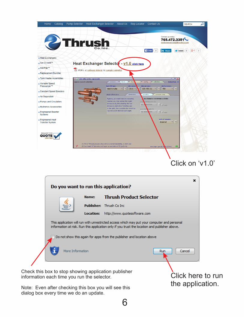
Navigate to the Thrush Co Inc home page at www.thrushco.com
Click ‘Heat Exchanger Selector’ at the top of the page.
Where is the selector?...
6
Click on ‘v1.0’
Check this box to stop showing application publisher information each time you run the selector. Note: Even after checking this box you will see this dialog box every time we do an update.
Click here to run the application.

7
More about the Java certificate verification
The first time you run our application and also each time we perform an update to our application you will see a dialog box asking permission to run the Java application. This is to help protect your computer from running java applications from untrusted sources. All you need to do if verify that the application you are running is from a trusted source. As you see below the source says ‘Thrush Co Inc’. We pay for a certificate that verifies that we are who we say we are so that you can rest assured that a Java application that says it is from Thrush Co Inc can be trusted and safely run on your computer.

8
Enter your login information that was provided to you by Thrush Co Inc.
If you need login information please contact [email protected].
Once you enter your username and password, press enter/return or click the green ‘check mark’.
Log In
9
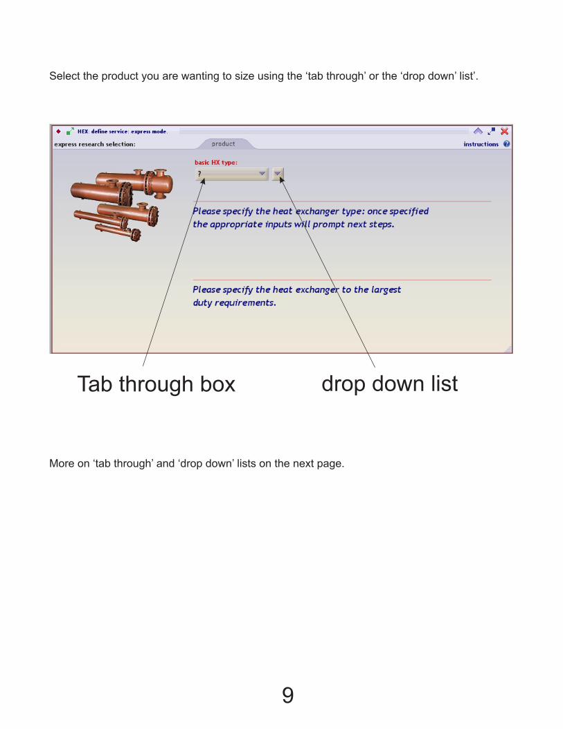
Tab through box drop down list
Select the product you are wanting to size using the ‘tab through’ or the ‘drop down’ list’.
More on ‘tab through’ and ‘drop down’ lists on the next page.
10
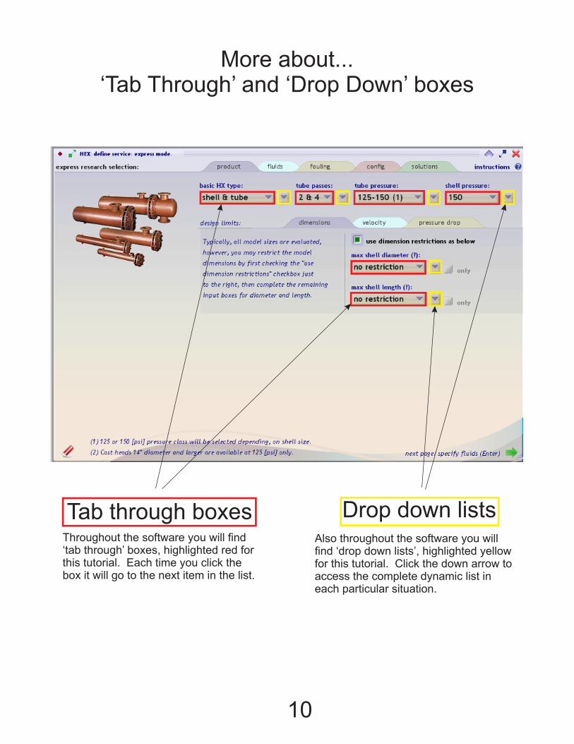
Tab through boxes Drop down listsThroughout the software you will find ‘tab through’ boxes, highlighted red for this tutorial. Each time you click the box it will go to the next item in the list.
Also throughout the software you will find ‘drop down lists’, highlighted yellow for this tutorial. Click the down arrow to access the complete dynamic list in each particular situation.
More about... ‘Tab Through’ and ‘Drop Down’ boxes
11
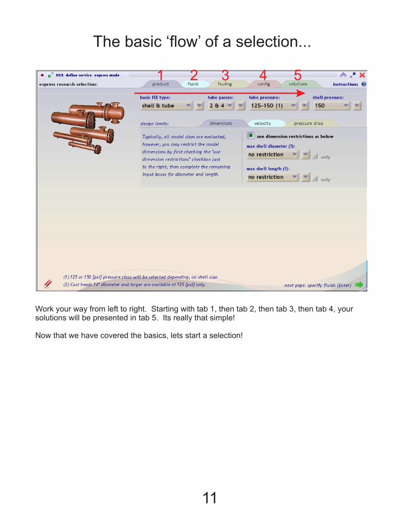
1 2 3 4 5
Work your way from left to right. Starting with tab 1, then tab 2, then tab 3, then tab 4, your solutions will be presented in tab 5. Its really that simple!
Now that we have covered the basics, lets start a selection!
The basic ‘flow’ of a selection...
12
For this tutorial we will be selecting a Thrush Shell and Tube heat exchanger that will meet the following conditions.
Steam to water unit
tube side:55 degree F, 30% propylene glycol solution, flowing at 125 GPM tube side out temperature required will be 155 degreesstandard pressure ratings
Shell side:35 pounds of saturated steamstandard pressure ratings
No restrictions on number of passes
There is a length restriction of 48” or less
Fouling .0005 overall.
Ok lets begin a selection...
We will start with a very basic selection to show how easy and fast a selection can be made. There are many more options and condition constraints available in the new selector as compared to the older version. These material and condition constraints are needed in order to make all the precise calculations necessary to produce a very detailed selection and submittal report that engineers and contractors require.
Once you get familiar with the software you will be able to do a basic selection like we are guiding you through in this tutorial, in less than 60 seconds. More detailed and constrained selections can also be done in less than 2-3 minutes, with a full submittal showing all calculated data, materials of construction, and dimensions of the product you have selected.

13
TAB #1 - PRODUCT
Use the ‘Tab Through’ or ‘Drop Down’ lists to select the following, based on the conditions in our example.
A) Product is a ‘Shell and Tube’ heat exchanger.B) No constraints on number of passes so select ‘2&4’ pass, this is the default.C) Tube side pressure is standard so select 125-150, this is also the default.D) Shell side pressure is standard so select 150, this is the default for shell side pressure.E) There is a constraint on the length of the heat exchanger. Click the ‘Dimensions’ tab beside ‘Design Limits’. Check the “use dimension restrictions as below” box.F) Select 48” from the list of length restrictions.
Note: On the length restriction if you only want to see 48” units, and not, 48” or below, then check the ‘only’ box next to 48” With the ‘only’ box unchecked, as above, you will get 48” and smaller units, this is what is required of our example.
If needed, on a more constrained selection, you can set velocity and pressure drop limits just as easily by using the ‘velocity’ and ‘pressure drop’ tabs under design limits.
That is all there is to this page! Either select the next ‘TAB’ or click the green arrow in the lower right hand corner.
A B C D
E
F
14
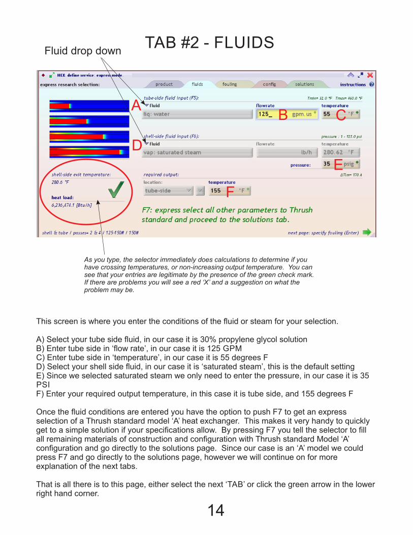
TAB #2 - FLUIDS
This screen is where you enter the conditions of the fluid or steam for your selection.
A) Select your tube side fluid, in our case it is 30% propylene glycol solutionB) Enter tube side in ‘flow rate’, in our case it is 125 GPMC) Enter tube side in ‘temperature’, in our case it is 55 degrees FD) Select your shell side fluid, in our case it is ‘saturated steam’, this is the default settingE) Since we selected saturated steam we only need to enter the pressure, in our case it is 35 PSIF) Enter your required output temperature, in this case it is tube side, and 155 degrees F
Once the fluid conditions are entered you have the option to push F7 to get an express selection of a Thrush standard model ‘A’ heat exchanger. This makes it very handy to quickly get to a simple solution if your specifications allow. By pressing F7 you tell the selector to fill all remaining materials of construction and configuration with Thrush standard Model ‘A’ configuration and go directly to the solutions page. Since our case is an ‘A’ model we could press F7 and go directly to the solutions page, however we will continue on for more explanation of the next tabs.
That is all there is to this page, either select the next ‘TAB’ or click the green arrow in the lower right hand corner.
Fluid drop down
AB C
D
E
F
As you type, the selector immediately does calculations to determine if you have crossing temperatures, or non-increasing output temperature. You can see that your entries are legitimate by the presence of the green check mark. If there are problems you will see a red ‘X’ and a suggestion on what the problem may be.

15
TAB #2 - FLUIDS - cont’d
Fluid drop down
A
D
Custom fluid properties may be entered by clicking the fluid drop down list.
Then clicking the ‘specify fluid properties’ tab. And then entering your custom fluid properties. and clicking the ‘use this data’ box.

16
TAB #3 - FOULING
Enter the fouling required for your selection. In our case it is standard .0005 total fouling.
Use the F5 key to auto-fill a total fouling of .0005. This puts half the fouling on the tube side and half on the shell side. For a total of .0005.
Also F6 can be used for a total fouling of .00024
Or you can enter a custom fouling factor according to your specifications.

17
TAB #4 - CONFIGURATION
There are 3 tabs to consider on this 4th screen.
A) Shell & Head Tab - This is where you enter required shell and head material. And you also specify the shell and head type. B) Tube Bundle Tab - This is where you enter information on the required material for the tube bundle, first single or double wall, then tube sheet material, finally tube material, tube size, and gauge required.C) Baffles Tab - Enter the required baffle material, baffle type (single segmented is the only choice at this time), and baffle cut (25% is standard)
Since we notice that our selection is a standard Thrush ‘A’ model all we need to do at this screen is press the F5 key or check the Auto-Fill button at the bottom of the page. This will fill all three tabs on this page with standard Thrush ‘A’ model materials and configurations.
Which are as follows:3/4” 20 Ga. single wall copper tubeCarbon steel tubesheetCarbon steel shellStandard carbon steel headCarbon steel, single segmented, 25% cut baffles
A B C

18
TAB #5 - SOLUTIONS
The solutions are sorted by diameter then length. Since pricing is not in the selector yet this is the logic we use to put the least expensive unit on top.
The next several pages will explain some of the features on the ‘Solutions’ page. We will divide it up into several pages so it is not cluttered up.
19
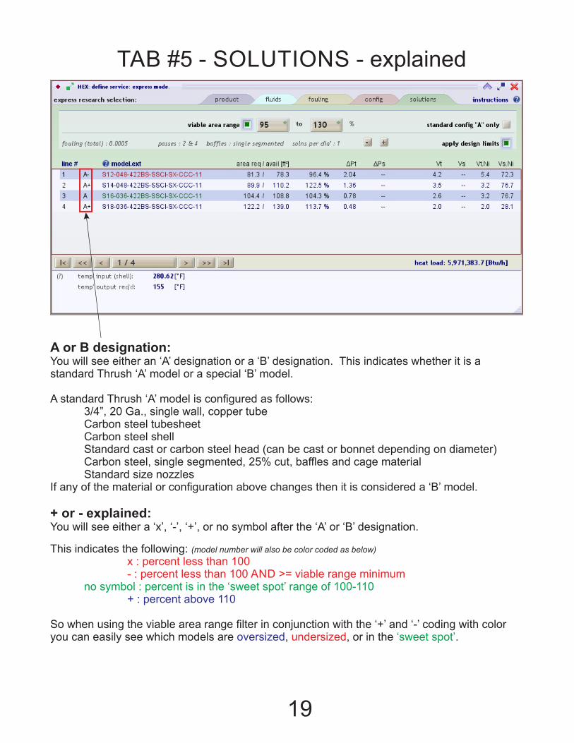
TAB #5 - SOLUTIONS - explained
A or B designation:You will see either an ‘A’ designation or a ‘B’ designation. This indicates whether it is a standard Thrush ‘A’ model or a special ‘B’ model.
A standard Thrush ‘A’ model is configured as follows: 3/4”, 20 Ga., single wall, copper tube Carbon steel tubesheet Carbon steel shell Standard cast or carbon steel head (can be cast or bonnet depending on diameter) Carbon steel, single segmented, 25% cut, baffles and cage material Standard size nozzlesIf any of the material or configuration above changes then it is considered a ‘B’ model.
+ or - explained:You will see either a ‘x’, ‘-’, ‘+’, or no symbol after the ‘A’ or ‘B’ designation.
This indicates the following: (model number will also be color coded as below)
x : percent less than 100 - : percent less than 100 AND >= viable range minimum no symbol : percent is in the ‘sweet spot’ range of 100-110 + : percent above 110
So when using the viable area range filter in conjunction with the ‘+’ and ‘-’ coding with color you can easily see which models are , , or in the .oversized undersized ‘sweet spot’

20
TAB #5 - SOLUTIONS - explained
Model nomenclature. This is the expanded model number, all configurations and materials are constrained by this model number. You can see an explaination of this nomenclature by clicking the ‘?’.

21
TAB #5 - SOLUTIONS - explained
Square foot of area required area available/area required
Square foot of area available

22
TAB #5 - SOLUTIONS - explained
Pt - Pressure drop tube side Ps - Pressure drop shell sideVt – Velocity in the tubeVs – Velocity in the shellVt.Ni – Velocity in the tube side inlet NozzleVs.Ni – Velocity in the shell side inlet nozzle

23
TAB #5 - SOLUTIONS - explained
This filter helps eliminate solutions that work but are not ideal. By default the range is set at 95% - 130%, and the filter is ‘ON’. You can change the range by typing in numbers that work for your situation or you can turn the filter off by ‘un-checking’ the green box.
Area Available/Area Required * 100

24
TAB #5 - SOLUTIONS - explained
This will toggle the number of solutions per diameter that show on the solutions page. By default it is set at 1.
Try this feature for a better understanding, click the & buttons.
Solutions per diameter

25
TAB #5 - SOLUTIONS - explained
Shows standard ‘A’ models only
Toggles ‘off’ and ‘on’ apply design limits that were set on the first ‘Tab’.

26
PRINTING A SUBMITTAL
Select the model that you would like to print a submittal for by clicking it in the list view.
Note: As you can see the solution on the top of the list is red meaning it is below 100% of surface area required, however, since we are using the ‘Viable Area Range’ filter, any solution down to 95% of the required area will show on our list. It is up to the discretion of the user to determine whether or not to use a unit that is slightly under sized as in this case.
27
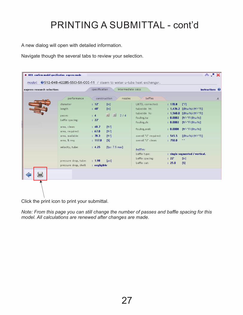
A new dialog will open with detailed information.
Navigate though the several tabs to review your selection.
Click the print icon to print your submittal.
Note: From this page you can still change the number of passes and baffle spacing for this model. All calculations are renewed after changes are made.
PRINTING A SUBMITTAL - cont’d

28
Fill in the dialog boxes with job specific information. Click the print icon.

29
Submittal Data
S12-048-42212" dia' / 48" len' / 4 passes / 78.3 ft²
U-tube heat exchanger
S12-048-422BS-SSCI-SX-CCC-11 (A) 2015 May 20
quote: 1234-A tag: MECH 11
job name: Hospital
location: Peru, IN
engineer: Bill Williamson architect: Tom Sharp
sales rep: Joe Mills contractor: Randy Martin
S : condensing steam on shell-side.
www.ThrushCo.com +1 (765) 472-3351
v.167-47
12 : nominal diameter in inches.
-
048 : nominal length in inches.
-
4 : count of tube-side passes.
22 : baffle plate spacing in inches.
B : baffle plate segment cut percent : ~ 25 %
S : baffle plate material : carbon steel
-
S : shell type : standard
S : shell material : carbon steel
C : head type. : cast
I : head material. : iron
-
S : inner tube sheet material : carbon steel
X : outer tube sheet material : not present
-
C : tube material : copper
C : tube size : 3/4"
C : tube gauge : 20
-
1 : tube-side pressure rating : 150 psig
1 : shell-side pressure rating : 150 psig

30
Submittal Data
S12-048-42212" dia' / 48" len' / 4 passes / 78.3 ft²
U-tube heat exchanger
S12-048-422BS-SSCI-SX-CCC-11 (A) 2015 May 20
service: tube side shell side
fluid: water saturated steam
flow rates: 125.0 gpm.us 6748.3 lb/h @ 35.0 psig
temp inlets: 55.0 280.6 F
temp outlets: 155.0 280.6 F
fouling: 0.0002 0.0002 (ft²·°F)/(Btu/h)
A
57.69"
B
4.31"
C
10.0"
D
32.75"
F
19.0"
inlet
6" FLG"
outlet
2" NPT
V
3" NPT
* Designed & constructed per ASME section VIII Div 1.
materials of construction:
shell: carbon steel
head: cast : iron
tube sheet: carbon steel
tubing: copper, 3/4"20ga
bundle cage: carbon steel
baffles: carbon steel
maximum operating conditions:
tube-side working pressure: 150 psig
shell-side working pressure: 150 psig
hydrostatic test press' tube-side: 300 psig
hydrostatic test press' shell-side: 195 psig
maximum temp' tube-side: 375 F
maximum temp' shell-side: 375 F
www.ThrushCo.com +1 (765) 472-3351
v.167-47

31
Submittal Data
S12-048-42212" dia' / 48" len' / 4 passes / 78.3 ft²
U-tube heat exchanger
S12-048-422BS-SSCI-SX-CCC-11 (A) 2015 May 20
process conditions tube-side shell-side
fluids: water saturated steam
flow rates: 125.0 gpm.us 6748.3 lb/h @ 35.0 psig
inlet temperatures: 55.0 280.6 F
outlet temperatures: 155.0 280.6 F
operating pressure: 150 35.0 psig
density: 61.7 0.117 lb/ft³
viscosity: 0.646 0.013 cP
heat capacity: 0.998 0.532 Btu/(lbm·°F)
thermal conductivity: 0.368 0.017 Btu/(h·ft·°F)
design criteria
max velocity 7.5 fps
max pressure drop 15 psig
fouling requested 0.0002 0.0002 h·ft²·°F/Btu
performance
velocity 4.25 fps --
pressure drop 1.98 psig --
heat transfer coefficient 1,476.2 1,560.0 (Btu/h)/(ft²·°F)
heat load 6,236,474.1 Btu/h
corrected LMTD 170.8 x 1.0000 = 170.8 °F
overall heat transfer coeff' 545.5 (Btu/h)/(ft²·°F)
total fouling available 0.0008 (ft²·°F)/(Btu/h)
required heating surface 67.0 ft² fouled, 48.7 clean.
construction
design rating 150 150 psig @ 375 °F
passes 4 1
inlet nozzle 3" NPT 6" FLG
outlet nozzle 3" NPT 2" NPT
materials
tubes copper, 3/4"20ga
tubesheet carbon steel
head cast : iron
shell carbon steel
baffles carbon steel
gasket non-asbestos
studs & nuts carbon steel
www.ThrushCo.com +1 (765) 472-3351
v.167-47
32
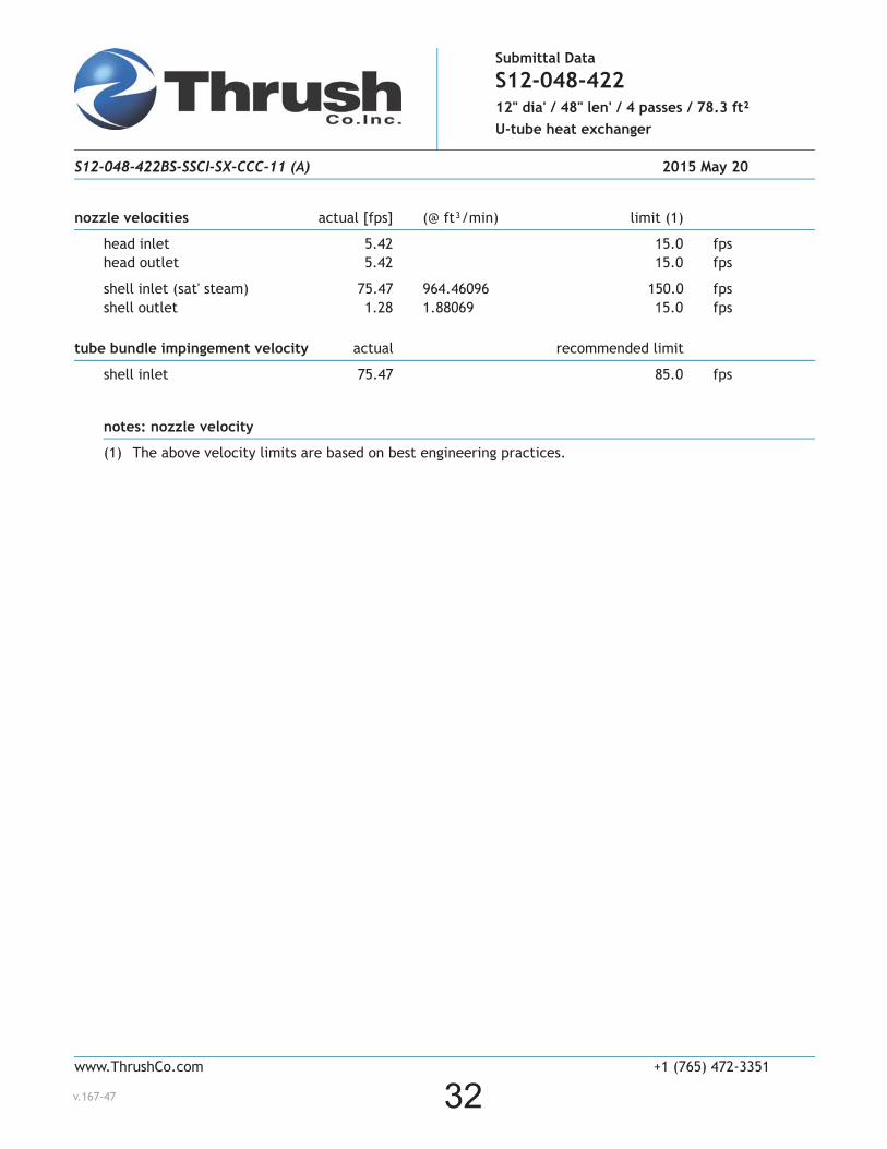
Submittal Data
S12-048-42212" dia' / 48" len' / 4 passes / 78.3 ft²
U-tube heat exchanger
S12-048-422BS-SSCI-SX-CCC-11 (A) 2015 May 20
nozzle velocities actual [fps] (@ ft³/min) limit (1)
head inlet 5.42 15.0 fps
head outlet 5.42 15.0 fps
shell inlet (sat' steam) 75.47 964.46096 150.0 fps
shell outlet 1.28 1.88069 15.0 fps
tube bundle impingement velocity actual recommended limit
shell inlet 75.47 85.0 fps
notes: nozzle velocity
(1) The above velocity limits are based on best engineering practices.
www.ThrushCo.com +1 (765) 472-3351
v.167-47


