THS II (TOYOTA HYBRID SYSTEM II) TH-36 J THS II CONTROL SYSTEM 1. General The THS II control system contains the following components. Item Outline THS ECU Control (See page TH-40) D The THS ECU calculates the target motive force based on the shift position, the degree to which the accelerator pedal is depressed, and the vehicle speed. It effects control in order to create the target motive force by optimally combining the power of MG1, MG2, and the engine. D The THS ECU calculates the engine motive force based on the target motive force, which has been calculated based on the requirements of the driver and the conditions of the vehicle. In order to create this motive force, the THS ECU appropriately controls the ETCS-i (Electronic Throttle Control System-intelligent) system, fuel injection volume, injection timing, and VVT-i (Variable Valve Timing-intelligent) system. D The THS ECU monitors the SOC of the HV battery and the temperature of the HV battery, MG1, and MG2, in order to optimally control these items. D The THS ECU effects monitor control to monitor the conditions of the HV batteries and cooling fan control to keep the HV battery and DC / DC converter at a predetermined temperature. Thus, it optimally controls these components. D When the shift lever is in the N position, the THS ECU effects shut down control to electrically stop MG1 and MG2. D For the purpose of protecting the circuit from high voltages and ensuring the reliability of the circuit shut down, the THS ECU effects SMR control through the use of 3 relays to connect and shut down the high-voltage circuit. D The THS ECU calculates the SOC by estimating the charging and discharging amperage of the HV battery, in order to effect condition control. D The THS ECU uses the temperature sensors that are provided on the HV battery module to monitor the temperature of the HV battery module and controls its temperature by optimally controlling the dedicated cooling fan. D The THS ECU controls the DC / DC converter in accordance with the temperature of the auxiliary battery, in order to control the charging of the auxiliary battery. MG1 and MG2 Main Control (See page TH-47) D MG1, which is driven by the engine, generates a high voltage (alternating current) in order to operate MG2 and charge the HV battery. It Also functions as a starter to start the engine. D MG2, which is driven by electrical power from MG1 or the HV battery, generates a motive force for the front wheels. D MG2 generates electricity to charge the HV battery (regenerative brake control) during braking, and when the accelerator pedal is not being depressed. D Speed sensors (resolvers) detect the speeds and the rotor positions of MG1 and MG2, and output them to the THS ECU via the MG ECU. D Temperature sensors mounted on MG1 and MG2 detect the temperatures and transmit them to the THS ECU. (Continued)
Transcript
THS II (TOYOTA HYBRID SYSTEM II)TH-36
THS II CONTROL SYSTEM
1. General
The THS II control system contains the following components.
Item Outline
THS ECU Control(See page TH-40)
The THS ECU calculates the target motive force based on the shift position,the degree to which the accelerator pedal is depressed, and the vehicle speed.It effects control in order to create the target motive force by optimallycombining the power of MG1, MG2, and the engine.
The THS ECU calculates the engine motive force based on the target motiveforce, which has been calculated based on the requirements of the driver andthe conditions of the vehicle. In order to create this motive force, the THSECU appropriately controls the ETCS-i (Electronic Throttle ControlSystem-intelligent) system, fuel injection volume, injection timing, andVVT-i (Variable Valve Timing-intelligent) system.
The THS ECU monitors the SOC of the HV battery and the temperature ofthe HV battery, MG1, and MG2, in order to optimally control these items.
The THS ECU effects monitor control to monitor the conditions of the HVbatteries and cooling fan control to keep the HV battery and DC/DCconverter at a predetermined temperature. Thus, it optimally controls thesecomponents.
When the shift lever is in the N position, the THS ECU effects shut downcontrol to electrically stop MG1 and MG2.
For the purpose of protecting the circuit from high voltages and ensuring thereliability of the circuit shut down, the THS ECU effects SMR controlthrough the use of 3 relays to connect and shut down the high-voltage circuit.
The THS ECU calculates the SOC by estimating the charging anddischarging amperage of the HV battery, in order to effect condition control.
The THS ECU uses the temperature sensors that are provided on the HVbattery module to monitor the temperature of the HV battery module andcontrols its temperature by optimally controlling the dedicated cooling fan.
The THS ECU controls the DC/DC converter in accordance with thetemperature of the auxiliary battery, in order to control the charging of theauxiliary battery.
MG1 and MG2 Main Control(See page TH-47)
MG1, which is driven by the engine, generates a high voltage (alternatingcurrent) in order to operate MG2 and charge the HV battery. It Alsofunctions as a starter to start the engine.
MG2, which is driven by electrical power from MG1 or the HV battery,generates a motive force for the front wheels.
MG2 generates electricity to charge the HV battery (regenerative brakecontrol) during braking, and when the accelerator pedal is not beingdepressed.
Speed sensors (resolvers) detect the speeds and the rotor positions of MG1and MG2, and output them to the THS ECU via the MG ECU.
Temperature sensors mounted on MG1 and MG2 detect the temperaturesand transmit them to the THS ECU.
(Continued)
TH
THS II (TOYOTA HYBRID SYSTEM II) TH-37
Item Outline
InverterAssemblyControl(See page
The inverter converts the direct current from the HV battery into analternating current for MG1 and MG2, or vice versa, in accordance with thesignals provided by the THS ECU via the MG ECU. In addition, the invertersupplies the alternating current from the MG1 power to MG2.
Via the MG ECU, the THS ECU sends the signal to the power transistor inthe inverter to switch between the U, V, and W phases of MG1 and MG2,in order to drive MG1 and MG2.
The THS ECU shuts down if it receives an overheating, over-current, orfault voltage signal from the inverter.
(See page TH-49)
BoostConverterControl
The boost converter boosts the HV battery nominal voltage of DC 244.8 Vup to a maximum voltage of DC 650 V, in accordance with the signalsprovided by the THS ECU via the MG ECU.
The inverter converts the alternating current generated by MG1 or MG2 intoa direct current. The boost converter reduces the DC 650 V to DC 244.8 V(for the HV battery) in accordance with the signals provided by the THSECU via the MG ECU.
DC/DC ConverterControl
The DC/DC converter reduces the nominal voltage of DC 244.8 V to DC12 V in order to supply electricity to the body electrical components, as wellas to recharge the auxiliary battery (DC 12 V).
This converter controls the voltage of the auxiliary battery to keep it constant.
Skid Control ECUControl(See page TH-52)
During braking, the skid control ECU calculates the required regenerativebrake force and transmits it to the THS ECU. Upon receiving this signal, theTHS ECU transmits the actual regenerative brake control value to the skidcontrol ECU. Based on this result, the skid control ECU calculates and executesthe required hydraulic pressure brake force.
Battery Control(See page TH-53)
The battery smart unit monitors the voltage, current and temperature of the HVbattery module and the voltage of the cooling fan, and transmits them to theTHS ECU.
Shift Control(See page CH-12)
The THS ECU detects the shift position (P, R, N, D, or B) in accordance withthe signal provided by the shift position sensor, and controls MG1, MG2, andthe engine, in order to create the driving conditions that suit the selected shiftposition.
During CollisionControl(See page TH-54)
During a collision, if the THS ECU receives an airbag deployment signal fromthe airbag sensor assembly or an actuation signal from the circuit breakersensor located in the inverter, it turns OFF the SMR (System Main Relay), inorder to shut off the entire power supply.
Cruise Control SystemOperation Control
When the cruise control ECU that is enclosed in the THS ECU receives a cruisecontrol switch signal, it optimally regulates the engine, MG1 and MG2 in orderto obtain the target vehicle speed, as determined through the driver control,from the combination of their motive forces.
The THS ECU informs the driver about the vehicle conditions and any systemmalfunctions by illuminating or blinking the indicator lights and warning lightslocated in the combination meter and using the warning indication of themulti-information display or the radio and player with display.
Diagnosis(See page TH-58)
When the THS ECU detects a malfunction, it performs a diagnosis and storesthe values relating to the failure.
Fail-Safe(See page TH-58)
When the THS ECU detects a malfunction, the THS ECU stops or controls theactuators and other ECUs in accordance with the data already stored in thememory.
THS II (TOYOTA HYBRID SYSTEM II)
02HTH34TE
: CAN (CAN No.1 Bus)
: Serial Communication
METER ECU
MULTI DISPLAY*
SKID CONTROL ECU
DATA LINK CONNECTOR3
CANH CANLGMT
GMTG
MG1
MG2MMTG
MMTRV, FD, MJ
P, R, N, D, BSHIFT POSITIONSENSOR
ACCELERATOR PEDALPOSITION SENSOR
VPA, VPA2
STOP LIGHT SWITCH
AIRBAG SENSORASSEMBLY
STP
ABFS
THSECU
REQ+
REQ–CLK+
CLK–HTM+
HTM–MTH+
MTH–
G0
HSDN
MGECU
INVERTER
BOOSTCONVERTER
INVERTERASSEMBLY
DC/DC CONVERTER
SMRP
NODD
VLO
SMRP
FRONT CIRCUITBEAKER SENSOR
AS1
SMRG
SMRB
JUNCTION BLOCK
SMRG
SMRB
TH-38
2. Construction
The configuration of the THS II control system in the ’07 Camry Hybrid model is shown in the followingchart.
The THS ECU detects the amount of effort applied to the accelerator pedal in accordance with the signalsprovided by the accelerator pedal position sensor. The THS ECU receives signals from the speed sensor(resolver) in the MG1 and MG2, and detects the shift position signal from the shift position sensor. TheTHS ECU determines the driving conditions of the vehicle in accordance with these pieces ofinformation, and optimally controls the motive forces of MG1, MG2, and the engine. Furthermore, theTHS ECU optimally controls the output and torque of these motive forces in order to realize lower fuelconsumption and cleaner exhaust emissions.
The THS ECU calculates the engine motive force based on the calculated target motive force, and bytaking the SOC and the temperature of the HV battery module into consideration. The value obtainedby subtracting the engine motive force from the target motive force is the MG2 motive force.
The THS ECU realizes the required engine motive force by properly effecting ETCS-i control, fuelinjection volume control, injection timing control, and VVT-i system control. Furthermore, the THSECU appropriately operates MG1 and MG2 in order to realize the required MG2 motive force.
Flow of Motive Force Calculation
TH
THS II (TOYOTA HYBRID SYSTEM II)
02HTH36Y
Accelerator PedalPosition Sensor
Shift PositionSensor
Battery Smart Unit
Voltage Current Temperature
SerialCommunication
THS ECU
Engine Control
MG1 and MG2Control
Regenerative BrakeControl
HV Battery ChargeControl
Temperature SignalMotor-Speed Signal
MG1 MG2
Inverter
MGECU
Boost Converter
DC-DC Converter
ETCS-i Control
Fuel InjectionVolume Control
Ignition TimingControl
VVT-i SystemControl
Skid Control ECU
Regenerative Brake Force Request
Speed Sensor Signal Transmission
CAN(CAN No.1 Bus)
Meter ECU
Multi-information Display Warning Light Buzzer
Audio Head Unit*
Information Display Warning Message
TH-41
System Diagram
*: Optional equipment
THS II (TOYOTA HYBRID SYSTEM II)TH-42
System Monitoring Control
The THS ECU constantly monitors the SOC (state of charge) of the HV battery. When the SOC is belowthe lower level, the THS ECU increases the power output of the engine to operate MG1, which chargesthe HV battery. When the engine is stopped, MG1 operates to start the engine, then the engine operatesMG1 to charge the HV battery.
If the SOC is low, or the temperature of the HV battery module, MG1 or MG2 is higher than the specifiedvalue, the THS ECU restricts the motive force applied to the drive wheels until it is restored to the normalvalue.
Shut Down Control
The MG1 and MG2 are shut down when the shift position is in the N position. This is because MG1 andMG2 must be stopped electrically as a means of shutting down the motive force, since MG2 is mechanicallyjoined to the front wheels.
TH
THS II (TOYOTA HYBRID SYSTEM II)
02HTH25Y
Service Plug
High-voltageFuse
HV Battery UnitSMRB
DC/DC ConverterSMRP
SMRG
: High-voltage: Low-voltage
(+)
(–)
Inverter Assembly
THSECU
SMRB (ON)
SMRP (OFF)
SMRG (OFF)
SMRB (ON)
SMRP (ON)
SMRG (ON)
SMRB (ON)
SMRP (ON)
SMRG (OFF)
SMRB (ON)
SMRP (OFF)
SMRG (ON)
02HTH38Y
TH-43
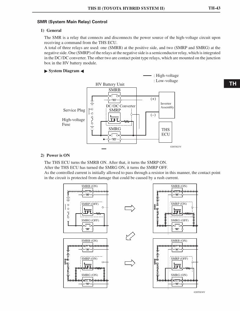
SMR (System Main Relay) Control
1) General
The SMR is a relay that connects and disconnects the power source of the high-voltage circuit uponreceiving a command from the THS ECU.A total of three relays are used: one (SMRB) at the positive side, and two (SMRP and SMRG) at thenegative side. One (SMRP) of the relays at the negative side is a semiconductor relay, which is integratedin the DC/DC converter. The other two are contact point type relays, which are mounted on the junctionbox in the HV battery module.
System Diagram
2) Power is ON
The THS ECU turns the SMRB ON. After that, it turns the SMRP ON.After the THS ECU has turned the SMRG ON, it turns the SMRP OFF.As the controlled current is initially allowed to pass through a resistor in this manner, the contact pointin the circuit is protected from damage that could be caused by a rush current.
THS II (TOYOTA HYBRID SYSTEM II)
02HTH39Y
SMRB (ON)
SMRP (OFF)
SMRG (OFF)
SMRB (OFF)
SMRP (ON)
SMRG (OFF)
SMRB (OFF)
SMRP (OFF)
SMRG (OFF)
SMRB (OFF)
SMRP (OFF)
SMRG (OFF)
182TH12
SOC
ControlRegion
Upper SOC control limit
Lower SOC control limit
Time
Example of change in SOC
Target SOC Control
TH-44
3) Power is OFF
First, the THS ECU turns the SMRG OFF. After it has determined whether the contact points of theSMRG are stuck, it turns the SMRB OFF.
Afterwards, the THS ECU turns the SMRP ON in order to determine whether the contact points ofthe SMRB are stuck. Then, it turns the SMRP OFF.
If the THS ECU detects that the contact points are stuck, it illuminates the master warning light andindicates “CHECK HYBRID SYSTEM” on the multi-information display, and stores a DTC(Diagnostic Trouble Code) in memory.
SOC Control
The THS ECU calculates the SOC (state of charge) of the HV battery by estimating its charging anddischarging amperages, in order to effect condition control.
While the vehicle is in motion, the HV battery undergoes repetitive charging/discharging cycles, as itbecomes discharged by the MG2 during acceleration and charged by the regenerative brake duringdeceleration. The THS ECU calculates the SOC based on charging/discharging levels detected by thecurrent sensor. The THS ECU performs the charging/discharging control based on the calculated valuein order to steady the SOC at its target level anytime.
TH
THS II (TOYOTA HYBRID SYSTEM II)
02HTH37Y
A/C ECU Cabin Temp.
CAN (CAN No.1 Bus)
THS ECU
Serial Communication
HV Battery Module
Temperature Sensors
BTH Battery Smart Unit
Battery Fan Relay
AuxiliaryBattery
Blower Motor (For Cooling Fan)
M
TH-45
Cooling Fan Control for HV Battery
The THS ECU monitors rises in the battery temperature through the four temperature sensors in the HVbattery module. Then, the THS ECU steplessly actuates the cooling fan under duty cycle control, in orderto maintain the temperature of the HV battery module within the specified range.
While the air conditioning system is operating to cool the cabin, if the HV battery module temperatureis within a normal range, the THS ECU turns the battery cooling fan OFF or changes the fan speed tolow speed. The purpose of this control is to give priority to cooling down the cabin, which also providescooling to the battery module through the intake duct located on the center of the rear package tray trim.
System Diagram
THS II (TOYOTA HYBRID SYSTEM II)
02HTH41Y
HV Battery
DC/DCConverter
Battery Temperature Sensor
THS ECU
Auxiliary Battery
288EG61C
(kΩ)
Resistance
0
Battery Temperature
(C (F))
TH-46
Auxiliary Battery Charging Control
1) General
The THS ECU controls the DC/DC converter in accordance with the signals from the batterytemperature sensor of the auxiliary battery, in order to control the charging voltage to the auxiliarybattery.
System Diagram
2) Battery Temperature Sensor
The battery temperaturesensor is installed on the battery.The battery characteristic (battery internal resistance) of taking in current for charging varies accordingto battery electrolyte temperature. If the electrolyte temperature is too low, the battery internal resistancewill increase, resulting in early deterioration. To prevent this, the battery temperature sensor changes itsresistance as shown below to detect the temperature.
Characteristic of Battery Temperature Sensor
TH
THS II (TOYOTA HYBRID SYSTEM II)
02DTH76Y
U V W IPM MotorGenerator
ON
ON
IGBT
(+)
(–)
U V W
02DTH77Y
U V W
ON
ON
(+)
(–)
U V W
02DTH78Y
U V W
ON
ON
(+)
(–)
U V W
TH-47
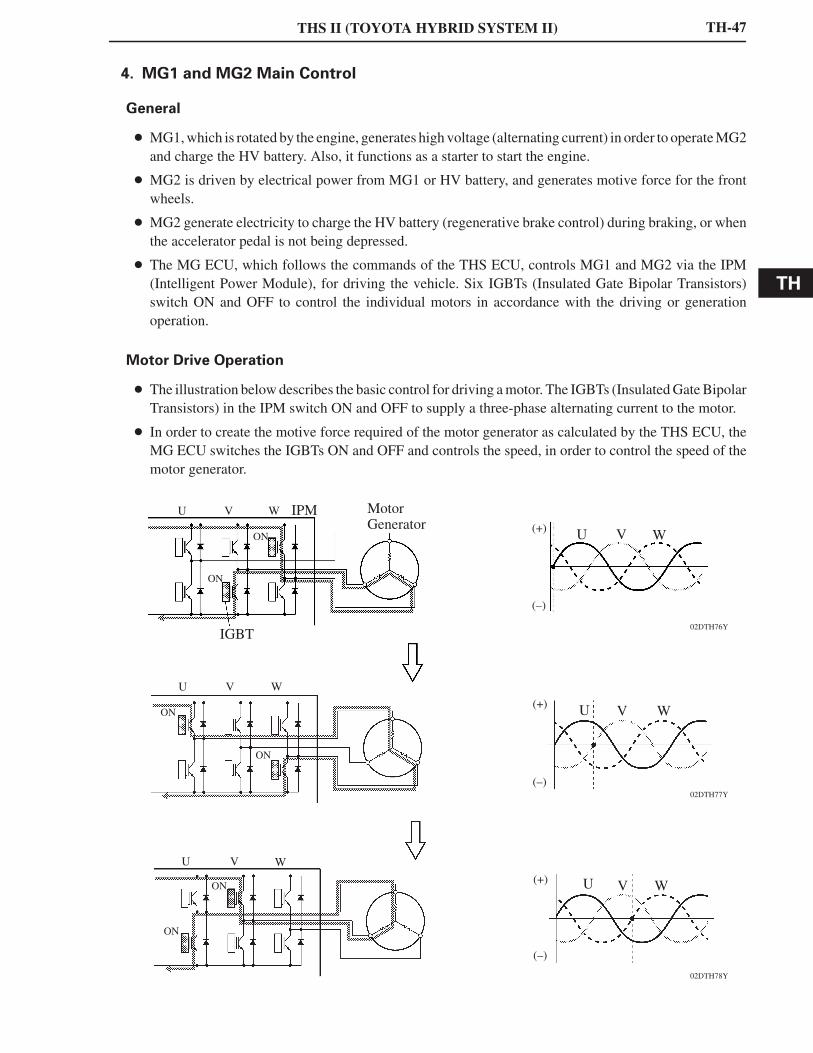
4. MG1 and MG2 Main Control
General
MG1, which is rotated by the engine, generates high voltage (alternating current) in order to operate MG2and charge the HV battery. Also, it functions as a starter to start the engine.
MG2 is driven by electrical power from MG1 or HV battery, and generates motive force for the frontwheels.
MG2 generate electricity to charge the HV battery (regenerative brake control) during braking, or whenthe accelerator pedal is not being depressed.
The MG ECU, which follows the commands of the THS ECU, controls MG1 and MG2 via the IPM(Intelligent Power Module), for driving the vehicle. Six IGBTs (Insulated Gate Bipolar Transistors)switch ON and OFF to control the individual motors in accordance with the driving or generationoperation.
Motor Drive Operation
The illustration below describes the basic control for driving a motor. The IGBTs (Insulated Gate BipolarTransistors) in the IPM switch ON and OFF to supply a three-phase alternating current to the motor.
In order to create the motive force required of the motor generator as calculated by the THS ECU, theMG ECU switches the IGBTs ON and OFF and controls the speed, in order to control the speed of themotor generator.
THS II (TOYOTA HYBRID SYSTEM II)
02DTH79Y
U V W IPM MotorGenerator (+)
(–)
V W U
02DTH80Y
U V W
(+)
(–)
V W U
02DTH81Y
U V W
(+)
(–)
V W U
TH-48
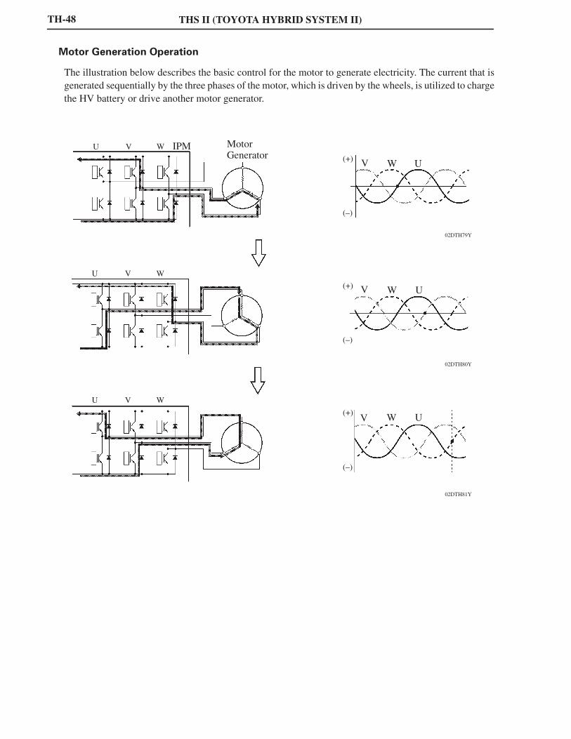
Motor Generation Operation
The illustration below describes the basic control for the motor to generate electricity. The current that isgenerated sequentially by the three phases of the motor, which is driven by the wheels, is utilized to chargethe HV battery or drive another motor generator.
TH
THS II (TOYOTA HYBRID SYSTEM II)
02HTH43Y
MG1 MG2
(3)
UVWIPM for Driving
UVWIPM for Driving
InverterAssembly
(1)
BoostConverter
(2)
MG ECU THS ECU
HV Battery
255TH70
HV Battery
NominalVoltage ofDC 244.8 V Boost
Converter
MaximumVoltage ofDC 650 V
Inverter
AlternatingCurrent MG1
MG2(1) Voltage Boost Conversion Function
255TH71
MG1
MG2
AlternatingCurrent
Inverter
MaximumVoltage ofDC 650 V Boost
Converter
NominalVoltage ofDC 244.8 V
HV Battery
(2) Voltage Drop Conversion Function
255TH72
MG1
AlternatingCurrent
Inverter
AlternatingCurrent
MG2
(3) Electrical Power Supply Function
TH-49
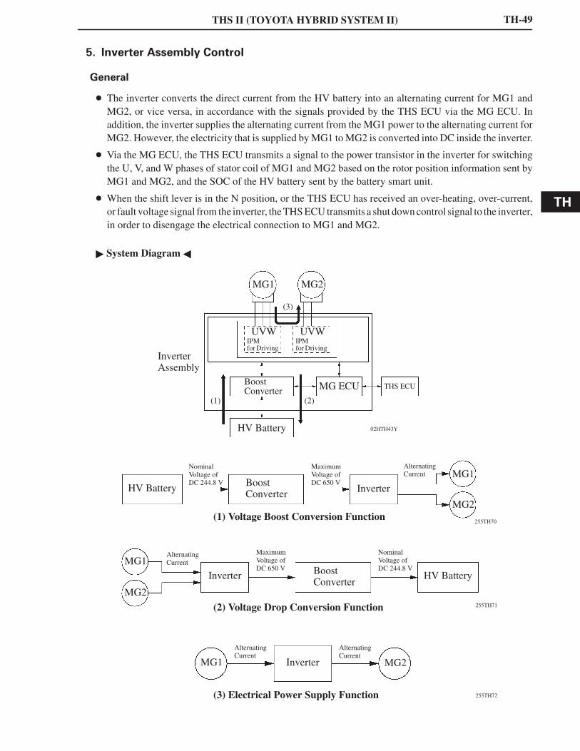
5. Inverter Assembly Control
General
The inverter converts the direct current from the HV battery into an alternating current for MG1 andMG2, or vice versa, in accordance with the signals provided by the THS ECU via the MG ECU. Inaddition, the inverter supplies the alternating current from the MG1 power to the alternating current forMG2. However, the electricity that is supplied by MG1 to MG2 is converted into DC inside the inverter.
Via the MG ECU, the THS ECU transmits a signal to the power transistor in the inverter for switchingthe U, V, and W phases of stator coil of MG1 and MG2 based on the rotor position information sent byMG1 and MG2, and the SOC of the HV battery sent by the battery smart unit.
When the shift lever is in the N position, or the THS ECU has received an over-heating, over-current,or fault voltage signal from the inverter, the THS ECU transmits a shut down control signal to the inverter,in order to disengage the electrical connection to MG1 and MG2.
System Diagram
THS II (TOYOTA HYBRID SYSTEM II)
02DTH82Y
Reactor
Nominal Voltageof DC 244.8 V
Boost IPMIGBT
(1)
(2)
IGBT
ON
Inverter
02DTH83Y
(1)
(2)
Maximum Voltageof DC 650 V
OFF
TH-50
Boost Converter Control
1) General
The boost converter boosts the nominal voltage of DC 244.8 V (for the HV battery) up to a maximumvoltage of DC 650 V, in accordance with the signals provided by the THS ECU via the MG ECU.
The inverter converts the alternating current generated by MG1 or MG2 into a direct current. Theboost converter drops the maximum voltage of DC 650 V to nominal voltage of DC 244.8 V (for theHV battery) in accordance with the signals provided by the THS ECU via the MG ECU.
The boost converter consists of a boost IPM (Intelligent Power Module) with built-in IGBTs(Insulated Gate Bipolar Transistors) that effect switching control, and a reactor that stores (andcharges) electrical power.
2) Voltage Boost Conversion Function
The function of the boost converter to boost the nominal voltage of the HV battery from DC 244.8V to maximum voltage of DC 650 V flows as described below.
The IGBT (2) turns ON, causing theelectrical power of the HV battery(nominal voltage of DC 244.8 V) tocharge the reactor. As a result, thevoltage in the reactor rises.
In the next stage, when the voltage inthe reactor rises to maximum voltageof DC 650 V, the IGBT (2) turns OFF,causing a counter electromotive forceto be created.
Induced by the counter electromotiveforce that is created, the electricalpower (maximum voltage of DC 650V) that is charging the reactor flowsinto the inverter.
TH
THS II (TOYOTA HYBRID SYSTEM II)
02DTH74Y
Nominal Voltageof DC 244.8 V
ON OFF Switching(Duty Control)
IGBT
(1)
(2)
IGBT
Maximum Voltageof DC 650 V
TH-51
3) Voltage Drop Conversion Function
The alternating current, which is generated by MG1 or MG2 for the purpose of charging the HV battery,is converted into maximum voltage of DC 650 V by the inverter. Then, a function of the boost converterdrops the voltage to nominal voltage of DC 244.8 V. This is accomplished by the IGBT (1) switchingON and OFF through duty cycle control, which intermittently interrupts the electrical power providedby the inverter.
THS II (TOYOTA HYBRID SYSTEM II)
02HTH46TE
MG1 MG2
Inverter Assembly
MG ECUETCS-iControl
Motor TractionControl (for ECB*)
MG2 MotiveForce Calculation
THS ECU
Battery Smart Unit
Battery Condition
(2)
(1)
Skid Control ECU
RequiredRegenerative BrakeForce Calculation
RequiredHydraulic BrakeForce Calculation
: CAN (CAN No.1 Bus)
: Serial Communication
Wheel Speed Sensors
Yaw Rate SensorDeceleration Rate Sensor
Steering Angle Sensor
Brake Pedal StrokeSensor
Brake Actuator
Master CylinderPressure Sensor(1, 2)
AccumulatorPressure Sensor
Wheel CylinderPressure Sensor(FR, FL, RR, RL)
(1) : Required regenerative brake force Required motive force (for TRAC or VSC Function)
(2) : Actual Regenerative Brake Control Value
TH-52
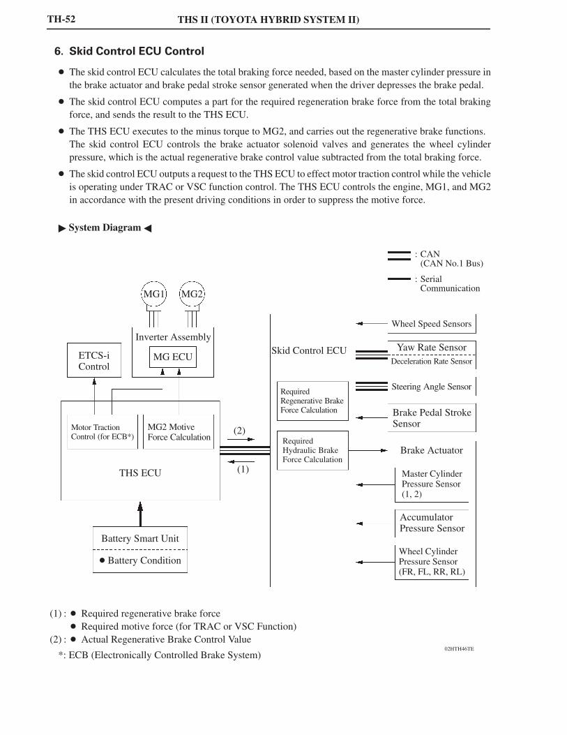
6. Skid Control ECU Control
The skid control ECU calculates the total braking force needed, based on the master cylinder pressure inthe brake actuator and brake pedal stroke sensor generated when the driver depresses the brake pedal.
The skid control ECU computes a part for the required regeneration brake force from the total brakingforce, and sends the result to the THS ECU.
The THS ECU executes to the minus torque to MG2, and carries out the regenerative brake functions. The skid control ECU controls the brake actuator solenoid valves and generates the wheel cylinderpressure, which is the actual regenerative brake control value subtracted from the total braking force.
The skid control ECU outputs a request to the THS ECU to effect motor traction control while the vehicleis operating under TRAC or VSC function control. The THS ECU controls the engine, MG1, and MG2in accordance with the present driving conditions in order to suppress the motive force.
System Diagram
*: ECB (Electronically Controlled Brake System)
TH
THS II (TOYOTA HYBRID SYSTEM II)
02HTH47TE
Current Sensor
Temp. Sensor Signal
Voltage
Battery Smart Unit
CPU
VoltageDetectionCircuit
LeakDetectionCircuit
SerialCommunication
Cooling Fan
THS ECU
HV Battery
TH-53
7. Battery Control
The battery smart unit detects and transmits the HV battery condition signals (voltages, currents, andtemperatures), which are used to determine charging or discharging values, to the THS ECU.
The battery smart unit also detects and transmits the cooling fan voltage signals which are necessary toeffect cooling fan control, to the THS ECU.
A leak detection circuit is provided in the battery smart unit in order to detect any excessive current drawfrom the HV battery.
System Diagram
THS II (TOYOTA HYBRID SYSTEM II)
02HTH20Y
Side Collision
AirbagSensorAssembly
CircuitBreakerSensor
FrontCollision
Impact
THS ECU SMR OFF
02HTH48TE
THS ECU
Circuit BreakerSensor
Airbag Sensor Assembly
TH-54
8. During Collision Control
General
If the vehicle encounters one of the situations described below, the THS ECU will shut down the entirepower supply by turning the SMR (System Main Relay) OFF, in order to ensure safety.
The THS ECU receives an airbag deployment signal from the airbag sensor assembly during a frontalcollision, or side collision.
The THS ECU receives an actuation signal for the circuit breaker sensor, which is provided in theinverter, during a frontal collision.
System Diagram
Layout of Main Components
TH
THS II (TOYOTA HYBRID SYSTEM II)
02HTH49Y
SOC Level Display
Multi-Information Display
02HTH50Y
SOC Level Display
TH-55
9. Indicator and Warning Light Illumination Control
Energy Monitor
On the ’07 Camry Hybrid model, the multi-information display located on the combination meter hasa function to display the energy flow, which enables the driver to monitor the driving conditions of thevehicle. The energy flow, which appears in the form of an arrow, also shows the SOC (state of charge)of the HV battery in 8 levels.
A radio and player with display, which is available as optional equipment, has a function to display theenergy flow with a style that differs from the multi-information display. This display also shows theenergy flow in the form of an arrow, and shows the SOC (state of charge) of the HV battery in 8 levels.
THS II (TOYOTA HYBRID SYSTEM II)
02HTH51Y
Master WarningLight
DischargeWarning Light READY Light
Combination Meter MalfunctionIndicator Lamp
TH-56
Indicator and Warning Light
1) Combination Meter
In particular, the indicator and warning lights associated with the THS II are described below.
Item Outline
READY Light
This light blinks when the driver simultaneously presses thebrake pedal and turns on the power switch while the shiftlever is in the P position. Thereafter, the light changes toillumination when the system starts, thus informing thedriver that the vehicle is drivable.
Master Warning Light
The primary function of this warning light, whichilluminates simultaneously with the sounding of a warningbuzzer, is to inform the driver in case of a malfunction in theTHS II system or other systems, or when the SOC of the HVbattery is lower than the standard.
Malfunction Indicator LampTurns on when there is a malfunction in the engine controlsystem.
Discharge Warning LightTurns on when there is a malfunction in the DC 12 Vcharging system (converter assembly).
TH
THS II (TOYOTA HYBRID SYSTEM II)
02HTH52TE
Multi-Information Display
02HTH53TE
Multi-Information Display
02HTH54TE
Multi-Information Display
02HTH55TE
Multi-Information Display 02HBE49Y
Radio and Player with Display
TH-57
2) Multi-Information Display
This warning display indicates to the driver thatthe SOC is lower than the minimum standardvalue (%). At the same time, the master warninglight blinks and the buzzer sounds.
This warning display indicates to the driver thata malfunction has occurred in the THS II system.At the same time, the master warning lightilluminates and the buzzer sounds. However,these are inactive for 5 seconds after the powersource is turned to IG ON.
This warning display indicates to the driver thatthe temperatures of any parts related to the THSII system exceed the standard value. At the sametime, the master warning light illuminates andthe buzzer sounds.
3) Multi-Information Display and Radio and Player with Display
Under the condition described below, the message prompt shown on the left below appears on themulti-information display screen. In addition, when the radio and player with display is fitted (onlyon models with the navigation with AV system), the caution message shown on the right below appearson that screen as well. These messages are accompanied by the blinking of the master warning lightand continuous sounding of the buzzer.
The READY light is illuminated, the shift position is in the N position, and the HV battery isdischarged.
THS II (TOYOTA HYBRID SYSTEM II)TH-58
10. Diagnosis
In the THS II, if the THS ECU detects a malfunction, the ECU performs a diagnosis and memorizes failedsections. Furthermore, to inform the driver of the malfunction, the ECU illuminates or blinks the MIL(Malfunction Indicator Lamp), master warning light, which pertains to the ECU.
The THS ECU will restore the respective DTC of the malfunctions.
Three-digit information codes have been provided in the conventional DTC as subset of a primaryfive-digit code. This enables the troubleshooting procedure to further narrow down a trouble area toidentify a problem.
The DTC can be accessed through the use of the hand-held tester with CAN VIM (Dedicated adapter).
For details, refer to the 2007 Camry Hybrid Vehicle Repair Manual (Pub. No. RM02H0U).
11. Fail-Safe
If the THS ECU detects a malfunction in the THS II, it will control the system in accordance with the datathat is stored in its memory.For details, refer to the 2007 Camry Hybrid Vehicle Repair Manual (Pub. No. RM02H0U).