63
THURBER ,CONSULTANTS- LTP., Oeotechnical Engineers 628 Dupplin Road, VICTORIA, British Columbia, Phone: 388-5184 c 'I' L
| Date post: | 26-Sep-2018 |
| Category: |
Documents |
| Upload: | nguyenhuong |
| View: | 214 times |
| Download: | 0 times |

THURBER ,CONSULTANTS- LTP., Oeotechnical Engineers
628 Dupplin Road, VICTORIA, British Columbia, Phone: 388-5184
c
'I' L

-
1 Library Spare COPY s e n t t o D i s t r i c t of Summerland, Nov. 2 9 , n -

h
iti
TROUT CREEK
GROUNDWATER STUDY
REPORT
to the
WATER RESOURCES SERVICE BRITISH COLUMBIA
January 1973 Thurber Consultants Ltd.
1
m
I
Thurber Consultants Ltd e
SYNOPSIS
An unusually high and persistent groundwater condition
developed in the Trout Creek area, near Summerland, following
the spring freshet in 1972 e
A field investigation was carried out September and October
1972 to determine the cause of the condition.
This report discusses the findings of the investigation and
advises on appropriate remedial measures. An immediate start
on a programme of creek channel improvements is recommended.
The estimated construction cost of this programme is $333,400.
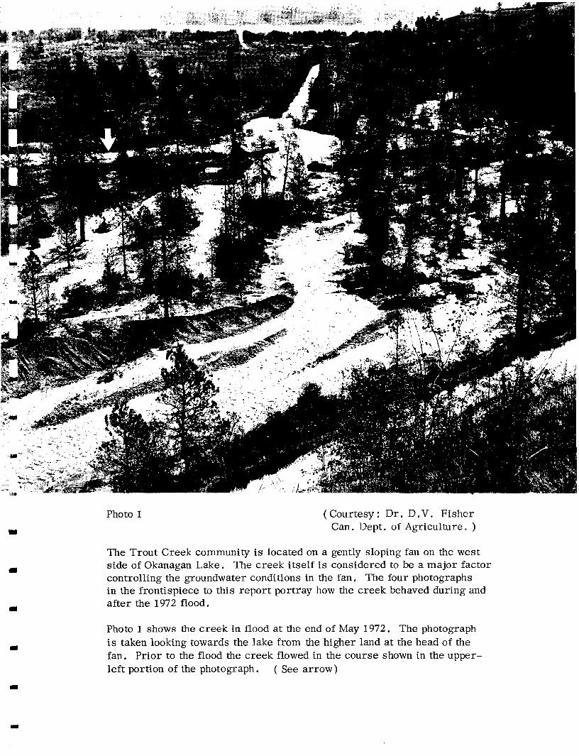
Photo 1 ( Courtesy : Dr. D.V. Fisher Can. Dept. of Agriculture. )
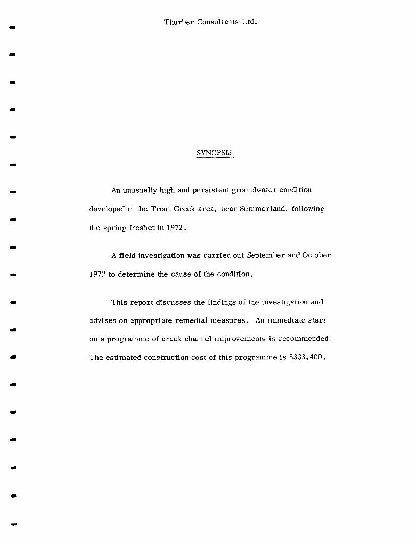
The Trout Creek community is located on a gently sloping fan on the west side of Okanagan Lake. The creek itself is considered to be a major factor controlling the groundwater conditions in the fan. The four photographs in the frontispiece to this report portray how the creek behaved during and after the 1972 flood.
Photo 1 shows the creek in flood at the end of May 1972. The photograph is taken looking towards the lake from the higher land at the head of the fan. Prior to the flood the creek flowed in the course shown in the upper- left portion of the photograph. ( See arrow)

Photo 2 ( Courtesy : Dr. D .V . Fisher Can. Dept. of Agriculture. )
Photo 2 and 3 were both taken from the same location, looking upstream from the Highway 97 bridge. Photo 2 was taken in May 1972 at the same time as photo 1 , and shows the creek in full flood ( approximately 2500 c .f .s. at its peak). Photo 3 was taken after the flood, November 1972.

Photo 3

Photo 4 I
A view of the Highway 97 bridge taken in November 1972, after the flood. The bridge was constructed in 1949. It was able to pass the 1972 flood without damage. However, as the flood abated, appreciable quantities of alluvium were deposited in the stream bed. There is now an inadequate clearance of only 4 feet ( average) between the stream bed and the deck beams.
I
I

Thurber Consultants Ltd e
INDEX
INTRODUCTION ........................................... 1 .
PROCEDURE . . . . . . . . . . . . . . . . . . . . . . . . . . . . . . . . . . . . . . . . . . . . . . 2.
DESCRIPTION OF AREA .................................. 3 .
THE 1972 FLOOD CONDITIONS ........................... 5 . THE PROBLEM...... ..................................... 6.
GEOLOGY ................................................ 9 .
THE PERPETUAL SLIDE .................................. 10.
ANALYSIS OF HYDROGRAPHS ............................. , 1 2 . THE CAUSE OF THE HIGH
GROUNDWATER CONDITION ......................... ,14 .
REMEDIAL MEASURES ................................... 17 .
PROPOSED CREEK CHANNEL IMPROVEMENTS .................................... 20.
m
SUMMARY . . . . . . . . . . . . . . . . . . . . . . . . . . . . . . . . . . . . . . . . . . . . . . . 25,

rl)
3
II)
Thurber Consultants L td .
INDEX (con't . )
PHOTOGRAPHS :
Photos 5 to 1 2 ( Photos 1 to 4 are contained in the frontispiece)
WELL DATA :
Water level readings for shallow observation wells 72 - 1 to 72 - 46 inclusive.
DRAWINGS :
Drawing 15-6-7-1 to -8 ( sheets 1 and 2)
LOGS :
Drill hole logs for observation wells 72 - 1 to 72 - 46 and testholes 72 - 1 to 72 - 16 inclusive.
V

Thurber Consultants Ltd.
INTRODUCTION
During 1972, following the spring freshet, an unusually high groundwater condition developed in the Trout Creek area near Summerland. This condition resulted in flooding of house basements, problems with septic tank installations, and some damage to orchards The condition continued into the early Fall.
The purpose of the study covered by this report is to investigate the nature and causes of the problem, and to advise on a course of remedial action.
The study was authorized by a letter from the Deputy Minister of Water Resources, dated September 5, 1972 ( File : 0253756).
PROCEDURE
Reference has been made throughout the study to the following previous work :
1. Flood frequency studies for Trout Creek were carried out in September, 1972 by Mr , D. E e Reksten of the'@ater Resources Braneb,
.i. 1
2. Two geological and groundwater reports have been compiled on the area Mr. E C Ha1stea.d of the Federal Inland Waters Branch prepared a report in February, 1972 entitled ' Trout Creek Pilot Study, Ground Water Report'. Subsequently, the Water Resources Service engaged a summer student, Mr, Alan N . Campbell, who prepared a report entitled "Reconnaissance on the Reported High Water Table, Trout Creek Fan, Okanagan, B . C," dated August, 1972,
3 . During 1969, 12 deep wells were installed in the Trout Creek fan by the Water Resources Service. The water levels in these wells have been read on a monthly basis.

Thurber Consultants Ltd .
4. In 1945, a subsoil map covering part of the fan was prepared by Mr . C . C. Kelly.
In addition to the above, copies of several let ters on the subject from Summerland Municipality and from local residents along with several newspaper clippings were provided to u s by the Water Resources 8r-h. ' , , IC
The field work for the study commenced in September 1972. The programme consisted of:
1 .
2 .
3 .
4.
5.
A topographic survey of the fan, in sufficient detail to permit the preparation of a contoured plan with a 2 foot interval.
A detailed survey of Trout C r e e k . A baseline, ex- tending from the lake to the head of the fan was es- tablished along the north side of the creek to an accuracy of better than 1 : 1000.
A systematic photographic record of the gradation and size of the gravel and cobbles exposed in and adjacent to the creek bed.
Installation of 46 shallow observation wells to supplement the information from the deep wells. The combined system of wells constitute an effective monitoring system.
An extensive canvass of the Trout Creek community. The purpose of the canvass was to obtain first hand information on the nature of the problems experienced by householders during 1972 and in previous years. Information was obtained on 176 houses out of an approximate total of 200 houses on the fan.
The field programme was followed by an analysis of the data to determine the cause of the high groundwater, and a course of remedial action was developed as discussed in the report.
2.

Thurber Consultants Ltd,
During the course of the work contact was established with several employees of Summerland Municipality. Messrs Harold Felker ( Superintendent) and Lloyd Metevier ( Municipal Clerk) were particularly helpful in supplying data and information
Prior to compiling this report our preliminary find- ings were reviewed and discussed with M,essrs. B.E. Marr and P .M, Brady of the Water Resources &an& at a meeting in Victoria on November 17, 1972.
DESCRIPTION OF AREA
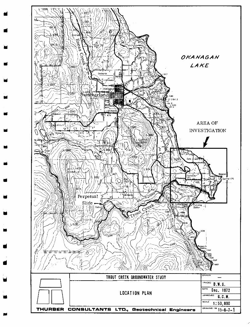
The Trout Creek community is located approximately 3 miles south of Summerland on a gently sloping alluvial fan, ( refer Dwgs 1 and 2 ) . The surface of the fan has an area of some 600 acres, and an average slope of 1: 100, Highway 97 passes through the qommunity.
The land is primarily used for fruit farming, although the area close to and fronting on the lake is prime residential property, Several very expensive homes are located on the', waterfront between Gartrell Point and the mouth of Trout Creek, The Federal Department of Agriculture owns and manages most of the area south of Trout Creek as a re- search station, There is a small irrigation dam on the creek at the head of the fan which i s the main source of water for irrigating the orchards. This dam is a small concrete drop structure with a c res t width of 114 feet and a 3 feet vertical drop,
Initially that portion of the fan which now lies east of Highway No. 97 was marshy. In 1946 M r C C. Kelly of the Provincial Department of Agriculture prepared a layout for subsurface drainage of part of this area north of Trout Creek* The system was subsequently installed by
* Footnote: A drawing showing the proposed layout is available in our files.
3 .

Thurber Consultants Ltd.
residents working on a volunteer basis. No design details of the system " as constructed" are available, and very little maintenance work has been carried out. Consequently, although parts of the system are undoubtedly working, much of i t has probably deteriorated and there is consider- able doubt about the present efficiency of the system.
After the heavy spring run-off in 1948, the Department of Highways undertook a programme of channel improve- ments on Trout Creek. The work consisted of straightening an appreciable portion of creek and constructing dykes. The cost of this work was shared by the residents of Trout Creek, Summerland Municipality, and the Federal and Provincial Governments. The work was completed in 1949, and since this time little maintenance of the channel has been done, except for the emergency measures in 1972.
The present bridge crossing of Highway No. 97 over the creek was also constructed in 1949.
The Trout Creek community has experienced a sub- stantial growth in the last 10 years, The following table indicates that of the 200 homes presently located on the fan, almost half of them were built during this period.
TABLE 1
Record of Building Permits Issued During 1962-72 for the Trout Creek Area ( Information supplied by Summerland
Municipality )
1962 I963 1964 1965 1966 I967 I968 1969 1970 1971 I972
2 6 3
12 11 11 14
3 7 9 9
Total 87
A l l the homes located on the fan are served by individual septic tank systems.
4.

Thurber Consultants Ltd.
THE 1972 FLOOD CONDITIONS
Spring, 1972 was a period of very high run-off, The peak daily discharge recorded at the mouth of Trout Creek on May 26 was 2530 c .f .s . A Gumbel probability plot has been compiled from past records at Faulder by the Water Resources Service* and is reproduced on Figure 1 . The 1972 peak discharge at Faulder is estimated to have reached 2350 c . f . s . which corresponds approximately to a 45-year recurrence interval. The 200-year discharge i s indicated to be 4100 c.f.s. ( o r approximately 4500 c .f.s. at the mouth of Trout Creek ) e
Photos 1 and 2 included in the ;frontispiece to this report show the river in flood, Upstream of the highway bridge, the creek overflowed its banks to the south and eroded several new channels. A small road bridge close to the head of the fan was washed out, but the flow managed to pass under the highway bridge without damaging it. At the mouth of the creek, the flow passed through 3 o r 4 old river channels out to the lake, The dyke on the north side of the creek was maintained inlctact throughout the flood period. The riprap protection on the creek-side of this dyke remained for the most part in good condition.
After the flood abated the flows returned to their former channel except at the upstream end where a bifur- cation of the creek still exists, as shown on Dwg. 2 e Also, the north dyke wasdeliberately broken at 2 locations upstream of the highway bridge to allow seepage water which had ponded in the orchards to flow back into the creek. These breaks are shown on Dwg. 8 ( sheet 1 ). There are also reports that fill has been removed from the crest of the north dyke downstream of the bridge.
* Footnote : Refer to Memo dated Sept. 28, 1972 from D.E. Reksten to H.I. Hunter, ( File 0256957). The plot is based on 25 years of records ( 1923-28 and 1935-54). Faulder is located 11 miles upstream of the mouth of Trout Creek.
5.

GUMBEL PROBABILITY PLOT
R e c u r r e n c e i n t e r v a l , i n y e a r s
Figure 1

Thurber Consultants Ltd.
I
II
il
rl
A s a result of the high run$off the level of Okanagan Lake was also unusually high. A plot of lake levels for the past 4 years has been included on Dwg. 7. The lake peaked at el. 1124.7 approximately one month after Trout Creek.
THE PROBLEM
An extensive canvass of the residents of Trout Creek was carried out during the period October 15-20, 1972.
Information was obtained on 176 houses ( there are approximately 200 homes on the fan). The canvass showed 79 ( 45% ) had experienced problems resulting from the high groundwater levels this year, The locations of these houses are shown on Dwg. 5. It should be noted that problems were reported from not only along the waterfront and adjacent to the creek, but also on the higher parts of the fan as much as 35 feet above lake level.
Detailed questionnaires were completed on 67 of these houses providing specific information on the extent of surface ponding, basement flooding, and septic tank problems. The results are summarised on Table 2 on the next page. One resident who reported a septic tank prob- lem also pumped water from a nearby well for domestic purposes. However, most of the residents used a piped water supply. Both the table and the drawing probably underestimate the actual overall magnitlnde of the septic tank problems ( see photos 9 and 10).
The location of the groundwater table during the time when the problems were reportedly greatest (July 1, 1972) is shown on Dwg. 6 in comparison with the con- ditions of early Fall ( September 25, 1972 ). The July conditions a re based on the water level readings from the 12 deep observation wells together with the information gained from the canvass with regard to flooded basements. The September conditions represent an interpretation of the water level readings from both the deep and shallow observation wells, a total of 58 wells, The following points a r e noteworthy :
6.

co M
cu
0
d
1
il
a, k
i k 0
I I rn k
cd a, s 0
k
w
0
d
u a, C a, 5
n
rn W
rn Q
) k
k
cd Q)
c,
m k iH‘
B a,
k
0
w
*d
C
m
k
cd a, h
% a, J2 m cd m cd 0
b rn 0
3
-3 c .i
3 2 5
a, 0
8 w
0
I
c,
cd 3
0 c
5
a, rn c,
II
I
a
a, m a, B
m E a“ i2 a,
a
rcl
0
\o d
w 0
.. c,
a,
*’
Thurber Consultants Ltd.
a
I
1)
1.
2 .
3 .
East of Highway 97 during July, the groundwater table rose to a very shallow depth of 4 feet or less and 2 feet or less over somewhat more than half of this area, Shallow groundwater conditions also existed above the highway.
During July, surface ponding occurred not only adjacent to the creek but also at various locations well removed from the creek as high a s 20 feet above lake level.
The shallow groundwater conditions continued through- out the summer period. The conditions for September 25, althougt.1 an improvement over those of July, still show most of the area of the highway with ground- water at a depth of 4 feet or less. This is compatible with the results of the canvass ( 14 householders reported persistent problems), and with the observed tree-kill in the orchards.
Another problem which affected the creek itself during 1972 was a marked aggradation of the creek bed. The bed of any mountain creek flowing over a fan will aggrade with time as material is brought down during periods of high run-off. Such a creek will eventually overtop its banks and erode a new channel. The cycle will repeat itself and the fan will grow. Trout Creek i s no exception and if the creek is to remain in its present channel it must be regularly maintained. The problem was accelerated in 1972 because of the very high runroff and the large amount of erosion of the upper part of the fan ( refer to photos 5, 6 and 7 ) . Figure 2 illustrates the amount of aggradation that has occurred at the gauging station below the highway bridge in the lower part of the fan. The gauge readings for the low flows of late summer 1972 are approximately 2 feet higher than the readings taken at the same time in 1971. A similar comparison made for the years 1971 to 1969 indicates that the bed aggraded by somewhat less than 0.5 feet in 1971 and experienced little or no aggradation in 1970. A s discus- sed later in this report the aggradation of the creek bed i s believed to be one of the causes of the continuing high groundwater condition but it also directly effects the security

2400
2000
1600 111
L
0 I
Y
ce 4
0 I
v)
0
r -1
4 0
CI 1200
-
- 800
400
0 klzk F M A M J J A S O N I
COMPARISON OF DISCHARGE AND GAUGE HEIGHT FOR TROUT CREEK ( S t a . N o . 0 8 N M 1 5 8 )
J F M A M J J A S O N O J F M A M J J A S O N O J F M A M J J A S O N
Figure 2

Thurber Consultants Ltd.
a
I
I
m
111
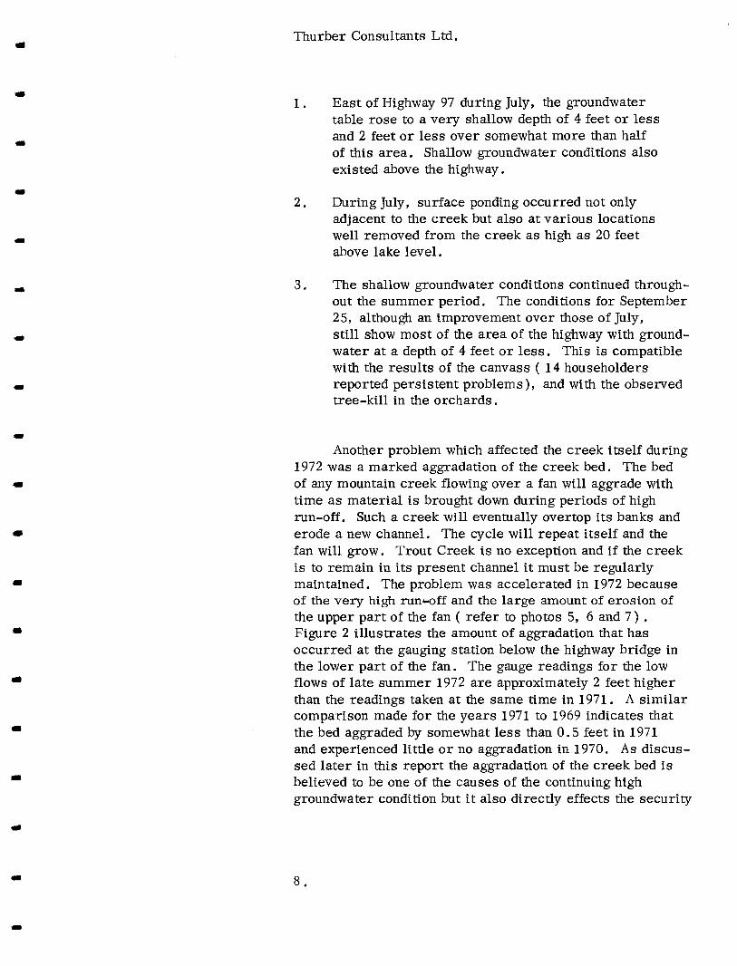
of the highway bridge. Figure 3 shows a number of rating curves for the bridge section assuming various conditions. The uppermost curve represents the present condition, with the creek bed as shown on Dwg. 8, sheet 2 . The ele- vation of the mderside of the bridge is indicated on the figure. It is apparent that the present channel under the bridge is inadequate to safely pass even an average peak discharge.
GEOLOGY
The drainage basin of Trout Creek covers an area of about 300 sq. miles. The creek is believed to have originated in pre-glacial r:mes when i t likely flowed into the Okanagan Lake area along a course gassing north of Giants Head Mountain ( refer to Dwg. I .). During the last glacial period the creek flow is bel i eved to have been diverted to the south, and the last 8 miles of the creek now flows through a ser ies of intersecting fault zones until it exits from the canyon at the head of the fan.
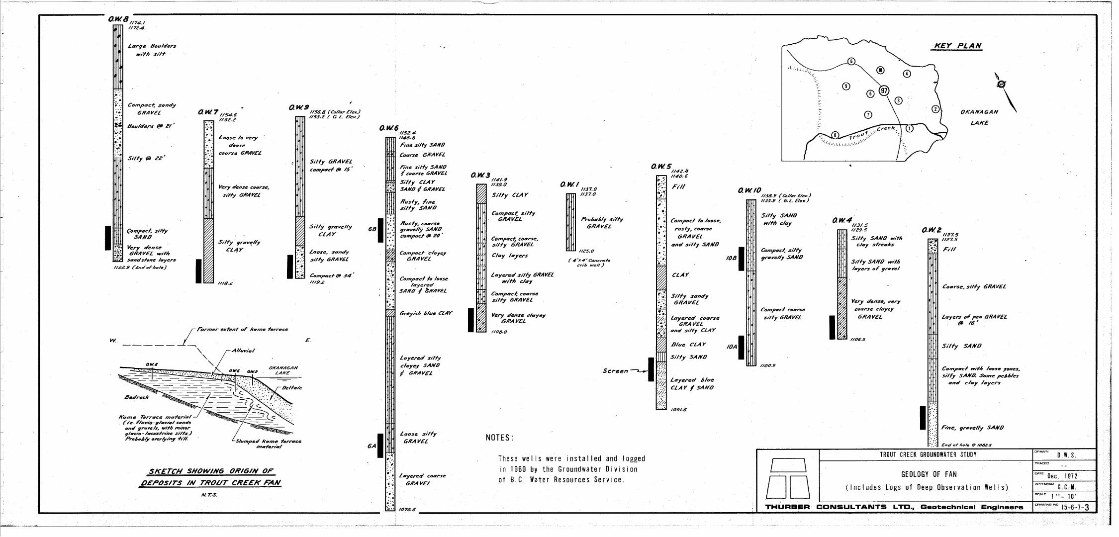
The origin of the deposits underlying the fan is depicted in the sketch on Dwg. 3 . The terraces flanking the fan contain materials which were deposited adjacent to a large body of deteriorating ice which occupied the Okanagan Valley. These materials consist sf layers of fine grain silts and clays laid down in temporary ponds, and also some sands and gravels deposited from streams running laterally to the ice. A s the ice melted the unsupported flanks of these deposits collapsed into the valley leaving 'kame' terraces. Subsequently, a3 at Trout Creek, mountain streams eroded through the terraces, reworking the ma- terial, and re-depositing the sand and gravel fractions as fans, Thus the material enccuntered in the deep observation wells above the highway i s probably in-tact o r slumped kame terrace material, overlain by reworked ( alluvial ) material. Below the highway, the wells penetrated for the most part reworked sand and gravel ( both alluvial and deltaic).
The detailed configuratfos, of a shallow groundwater table for given hydraulic boundary conditions is governed by the various permeability characteristics of the near- surface soils, The map provided on Dwg. 4 illustrates
m
1
I
1
1
0
z
I- o
v)
W
cl W
0
-
- a m
hz W
W
a 0
I- 3
0
I- a
a 0
LL
v)
>
W
02
3
o
W z
I-
4 a
W
I-
4
=E
-
-
x 0
a
a
4
n \
r
M
L-
v)
.- x
Y
._
J

Thurber Consultants Ltd.
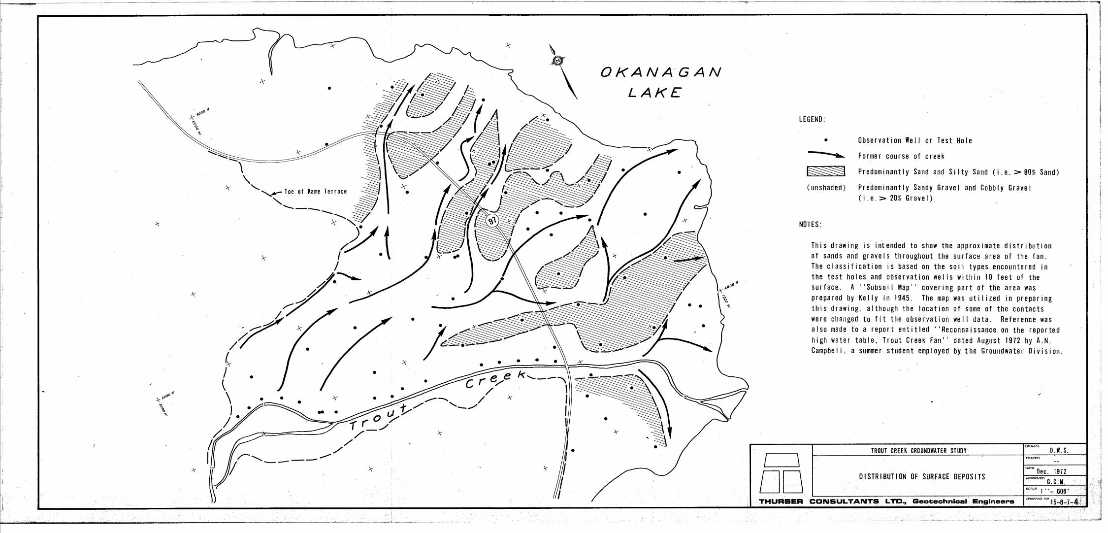
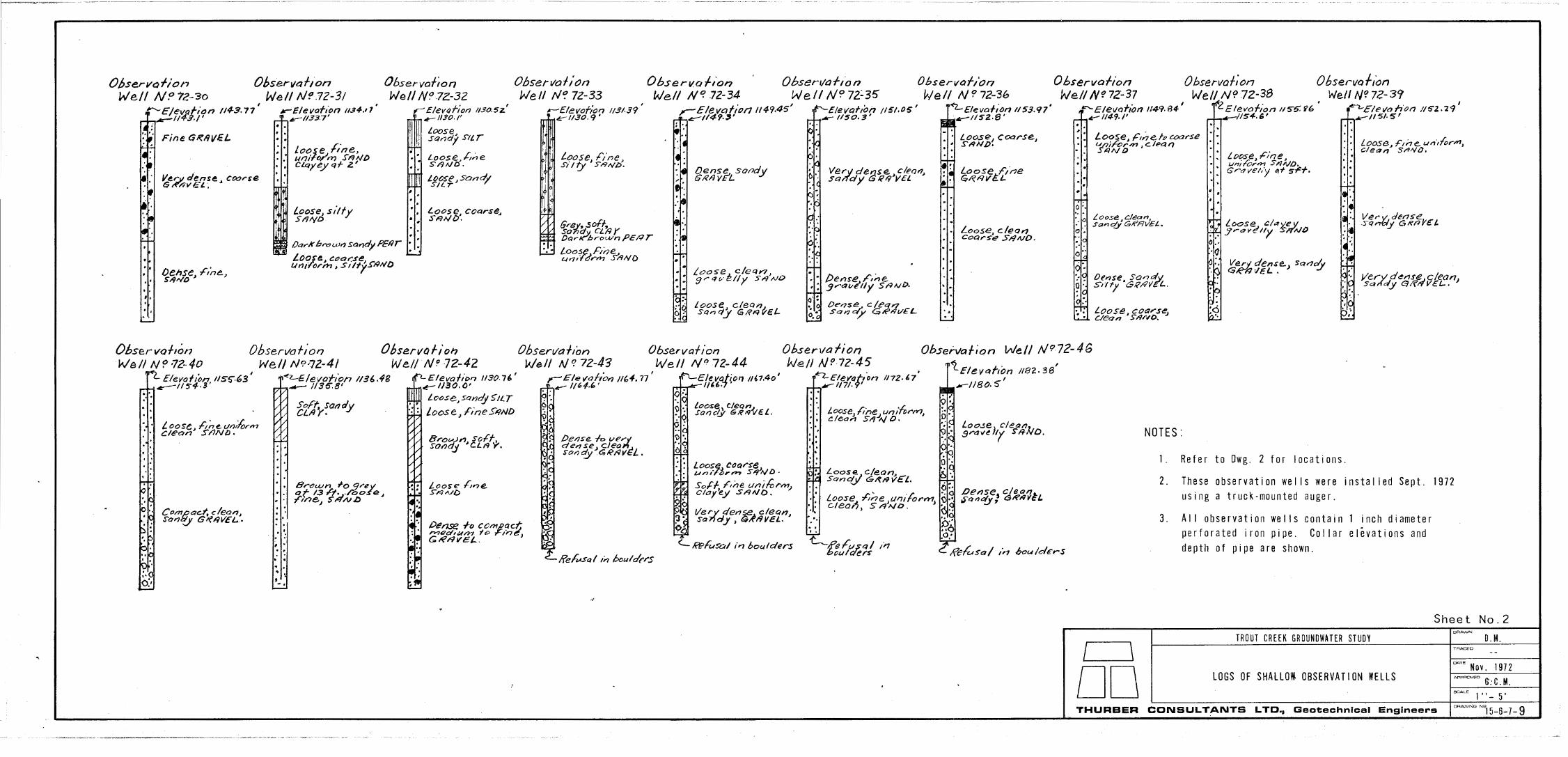
the distribution of silt or sand, and gravelly soils occur- ring within 10 feet of the surface through0u.t the fan. The map is based primarily on the drilling records for the shallow obs ervation wells and test holes , the logs of which have been included in the Appendix. The map clearly shows the accumulation of finer materials in the lower part of the fan, and coarser, more pervious gravels higher up towards the head of the fan. Some of these gravels were so coarse that it was not possible to auger through them to any appreciable depth Comparing Dwgs a 4 and 6, it will be noted that below the highway and away from the creek, the areas of very shallow groundwater generally correlate with the sandy areas, whereas the gravelly areas generally gave rise to a deeper groundwater table. Dwg. 4 also shows the locations of some of the former courses* taken by the creek as the fan was built up,
THE PERPETUAL SLIDE
A large rock and earth slide is located on the north bank of Trout Creek in the canyon approximately 2 miles above the head of fan ( refer to Dwg. 1 ) . The slide is of longstanding and moves intermittently; it is known locally as the "Perpetual Slide". Photographs sf the area are provided in the Appendix ( photo P 1 and 12 ) . The slide mass is 1500 feet wide and extends up about 300 feet above the creek. Although an investigation of the slide was not within the terms of reference of this study, a brief inspection of the area was carried out.
The movements are deep seated and appear to be occurring in weathered sandstones which are overlain by silty gravels. The toe of the slide i s at o r possibly slightly above the level of the creek. Springs are visible in the slide mass particularly at the bedrock contact. The slide is believed by Halstead to be located at the end of a buried channel, which mns from the north between
* Footnote : As interpreted from air-photographs.
10.
Thurber Consultants Ltd
I Giants Head Mountain and Mt. Conk-i.e, possibly a former course of Eneas Creek, The buried channel receives water from Prairie Creek.
Since the valley at the location of the slide is a very narrow canyon, consideration was given by Halstead to the likelihood of a sudden large movement occurring with the resulting hazard of a blockage which when over- topped could lead to a catestrophic flood downstream. Halstead concluded in l-iiis report that " there is probably no possibility of sliding on such a large scale" as long as the present groundwater conditions remain unchanged*.
W e support this opinion. There is abundant evidence that movements are progressively and slowly occurring, and that the toe of the slide mass is being eroded by the river. However there is no evidence that any rapid move- ments of large portions of the slide have occurred recently. It is probable that the failure plane is well established and that, as a result of prior movements, the shear strength characteristics are close to the residual state ( i .e. exhibit little o r no cohesion and sensitivity). If this is the case, rapid movements are unlikely provided there are no unusual changes in the other factors which control the movement of the slide. However it must be stressed that the foregoing remarks on the future perform- ance of the slide, are preliminary and are not supported by any detailed investigation. I
Many of the local residents have expressed the opinion that the slide constitutes a continuing source of silt and sand which is carried down by the creek and deposited in the interstices of the gravel lining the creek bed on the fan, thus partially sealing the gravels. We have no direct evidence that this has occurred, but it is plausible. Such a seal would however tend to be inefficient and of a - temporary nature, since the seal would tend to be removed during periods of high flows and bedload movements.
* Footnote : Halstead implies that changes in the ground- water conditions may result if any significant changes are made to the storage reservoir at the head of Prairie Creek.
Thurber Consultants Ltd
ANALYSIS OF HYDROGRAPHS
I
I
a
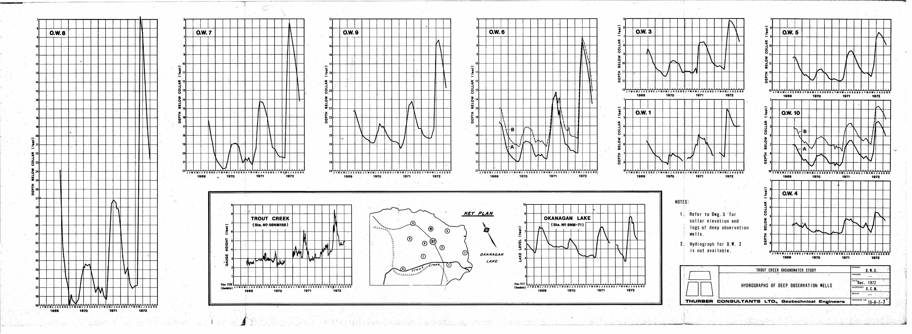
The hydrographs for the deep observation wells are reproduced on Dwg. 7 , To facilitate their comparison they are La.rmngeuI in order of distance from the head of the fan.
The behaviour of the creek and the lake are important factors ( although not the only ones) governing the location of the groundwater table within the fan. This is apparent from the pattern of the hydrographs. They all show a very high peak in 1972, a moderate peak in 1971, a low peak in 1970 and a moderate peak ( inferred) in 1969 An identical pattern is exhibited by the lake level and creek gauge height plots.
The magnitude of the differences between the peaks and the lows throughout the 1969-72 period appears to be a function of the distance of the well both from the head of the fan and from the present course of the creek. 0. W . 1 and 0. W . 8 are both very close to the creek However, 0 .W. 8 which is located close to the head of the fan exhibited very large fluctuations in water level, much larger than the changing level of the creek. By comparison, the water level changes in O.W. 1 are very similar to those experienced by the creek. The water level fluctu- ations of 0. W. 1 on the other hand are greater than those of 0. W. 10 which is located at about the same distance from the head of the fan as 0. W . 1 but is further removed from the creek. A detailed analysis of the hydrographs does reveal a few exceptions to this trend especially where the wells are located in former courses of the creek, but it is evident that there is a considerable influx of water into the fan from the higher reaches of the river during periods of high discharge.
In 0. W . 6 and 0 .W. 10, screens were installed close to the surface ( screen B ) and at depth. ( screen A ) , In both cases the hydrograph for the shallow screen showed water levels slightly higher than those corresponding to the deep screen. This occurrence is compatible with normal flow net considerations and does not necessarily indicate independent groundwater systems.
12 I
m
rl
m
Thurber Consultants Ltd
The timing of the peaks of the hydrographs $ in general agreement with what would be expected from consideration of the following factors:
1 e The relative changes in creek level and lake level ( the lake peaks about one month after the creek)
2. The time lag effect, (which is a function of soil permeability and distance from the boundary con- di tions ) .
3. Irrigation, which commences in the summer months and continues until the end of September. ( Some areas are irrigated more than others, and some not at all. However, a policy of irrigating orchards whether they need i t o r not seems to be followed. In 1972, orchard irrigation was observed in areas where trees were dying because of a high groundwater table ) . The time lag effect is illustrated by the comparison
of the 1972 hydrographs of 0 . W . 's 3, 8, and 9. These wells a re sufficiently removed from the influence of the lake so that effect of the spring influx of creek water is clearly indicated, Note that the point of origin ( on the creek ) of the groundwater encountered in the observation wells differs from well to well. This i s illustrated in Figure 4 which depicts flowlines drawn from the contours of the groundwater table for conditions as they existed on September 25, 1972. The pattern of the flowlines for June and July would be basically similar, although they would show a more marked tendency for the groundwater to originate towards the head of the fan. In 1972, 0 , W . 8 which is located close beside the creek peaked simultane- ously with the creek. The water levels in 0. W. 3 peaked approximately 4 weeks* later, the groundwater having travelled 2000 to 2500 feet from its point of origin, and the groundwater in 0. W. 9 peaked about 6 weeks* after
* Footnote : The deep observation wells are normally read ~~
on a monthly basis. Some "rounding-off' of the curves from those shown was necessary to compute the delay.

I
I
I
1
1
a
FLOWLINES FOR GROUNDWATER C O N D I T I O N OF SEPTEMBER 2 5 , 1 9 7 2
/ Groundwater depth
[ G r o u n d w a t e r e l e v a t i o n
S c a l e : 1 ”- 1 0 0 0 ’
Figure 4

Thurber Consultants Ltd.
the creek,! having.travelled 3000 feet o r so from its point of origin.
The effect of the influx of creek water is barely apparent in 0. W. 's 4, 5, and 10. These wells a re located low down on the fan and well removed from the creek ; their hydrographs reflect primarily the influence of the lower hydraulic boundary condition ( i .e. the lake). Compare the asymmetric form of the peaks of the hydrographs for these wells and the lake level plot with the symmetry of the gauge height plot and the hydrographs of the wells located higher up the fan above the highway. The rising lake level causes the groundwater seeping through the fan to back-up in an attempt to re-establish equilibrium*. Again, this requires time and hence the hydrographs for the above wells peak after the lake. The asymmetry of the hydrograph peaks of the wells close to the lake i s probably enhanced by the addition of water from irri- gation-.
The hydrograph for 0. W . 8 shows an additional item of interest. The peak for 1971 is shown as occur- ring 2 to 4 weeks after the peak for Trout Creek, whereas in 1972 the two peaks occurred almost simultaneously, implying that the influx of water from the creek into the groundwater system was not only greater in 1972 but occurred more rapidly.
THE CAUSE OF THE HIGH GROUNDWATER CONDITION
The high groundwater condition of 1972 differed from previous years in the following ways :
1 The groundwater in June and July was higher than usual for that time of the year.
* Footnote : It is probable that the flow conditions in the fan a re in a transient state throughout a period commencing with the spring freshet and continuing into the fall.
14.

Thurber Consultants Ltd.
2. The groundwater remained high throughout the summer period and into the early fall. At the end of October the recorded groundwater levels were at and sometimes above the peak levels of the pre- vious year.
3 . The condition affected appreciable areas above Highway 97.
These findings are supported by direct readings from wells, by observations of the various effects of the condition, and by an extensive canvass of the residents of the Trout Creek Area. However, it is our opinion that the portion of the fan below the highway and particularly along the waterfront has always been susceptible to this problem. In some parts of this area the groundwater level is at times normally so close to the surface that a difference of less than a foot would lead to noticable problems. W e feel that the situation at these locations is a marginal one with a considerable number of pre- existing problems.
The factors which may have contributed to the 1972 condition are listed below :
1. High Discharges Accompanied By Erosion
As the level of the creek rises with higher discharge the influx of water into the ground increases because of the increasing area of infiltration. If the high discharges are accompanied by overtopping into other channels, as happened in 1972, the area of infiltration can be disproportionately increased. It should be noted that even after the 1972 freshet the creek in the upper part of the fan continued to flow through two separate channels, A s mentioned pre- viously a considerable amount of erosion and bed load movement in the upper part of the fan accompan- ied the 1972 freshet. Thus any natural seal of deposited sil t would be quickly and effectively removed. The substantial and rapid influx of creek water into

Thurber Consultants Ltd.
I
il
1
I
I
I
1
the ground as discussed in the previous section can be explained by these mechanisms. The higher river levels alone are probably not very important, since they a re very temporary.
2. Aggradation of the Creek Bed
The aggradation of the bed of the lower part of the creek has permanently raised the river level. For example a t the gauge location the creek level through- out August to October 1972 when the discharge was less than 30 c .f s . corresponded to the creek level during 1971 when it was discharging 400 cif. s. during the freshet ( see Figure 2). This factor is undoubtedly a major contributor to the high groundwater condition within the proximity of the lower reach of the creek, but has relatively little affect elsewhere. ( refer to Figure 4).
3. High Lake Levels
Although Okanagan Lake did not attain record levels, 1972 was an exceptional year. The lake level reached el. 1124.7, and was a t o r above el. 1124 for almost two months The recorded maximum ( instantaneous) elevation is 1126.2 ( 1948), , but since 1956 an attempt has been made to maintain the level as fa r as possible below 1123.8. The high lake level is believed to have been primarily responsible for the high groundwater condition in the lower part of the fan.
4. Irrigation By Sprinkling
W e a re not able to quantitatively assess the role of sprinkling as a contributor to the groundwater con- dition. Sprinkling was terminated in 1972 around the end of September. The tabulated readings of water levels taken in the shallow observation wells a re provided as an appendix to this report. The levels in those wells above the highway fell off at a slightly increasing rate after September. This may have been caused by the termination of sprinkling.
16.

Thurber Consultants Ltd.
5 . Deterioration of Existing Drainage Facilities
The existing subsurface drainage works are now over 25 years old, It is to be expected that plugging and occasional collapse of the pipes and conduits has occurred with time, causing the system to pro- gressively deteriorate. However, this deterioration is unlikely to result in a noticable change in the groundwater levels from one year to the next. Also, since the drainage works are very shallow the effect of the deterioration outside of the area of their installation would be very limited.
Items 1 , 2 and 3 of the factors listed above represent the most significant changes from previous years.
REMEDIAL MEASURES
The need for remedial work is evident, Aside from the high groundwater condition, there is an existing hazard to the highway bridge and an increased danger of overtopping the dykes bordering the lower part of the creek channel. These problems will continue to worsen with time.
The remedial measures listed below a re capable of relieving the situation in varying degrees :
I . Creek Channel Improvements
Excavation of the bed of the existing creek would im- prove the groundwater condition by permanently lowering the creek level. Such excavation is also the only suitable means of improving the capacity of the channel under the bridge. Dykes on both sides of the creek would still be required to confine the flood discharges to one channel. The existing bifurcation of the creek in the upper part of the.fan should be eliminated to minimise the area of infiltration. Also the channel should be designed to minimise bed load movement in the upper part of the creek, to reduce maintenance and preserve as far as possible any seal caused by the accumulation of fines.
1 7 .
Thurber Consultants Ltd e
2 . Installation of a Partial Cut-Off
I
I
I A cut-off may be installed along the north side of the creek in the upper part of the fan. A t this time it should be assumed that such a cut-off will not be completely effecient, although further more detailed investigation may identify an impewious material at a suitable depth for the cut-off to tie into. However, the horizontal permeability can be expected to be greater than the vertical permeability and if the cut-off was taken to a depth of at least 30 feet, it could appreciately reduce the influx of water from the creek into the upper part of the fan during periods of high discharges Since the groundwater throughout most of the fan originates mainly from the upper part of the creek ( refer Figure 4 ), such an installation would provide obvious benefits. However, the construction of a suitable cut-off through the very coarse pervious materials which prevail towards the head of the fan would be costly. Also more investigation than has been carried out to date would be required to ensure a reasonable degree of success.
3 , Installation of Subsurface Drains
A system of subsurface drains could be suitably used to supplement such measures as those des- cribed under items P and 2. They may be installed to relieve a local situation where the groundwater remained stubbornly high. To be effective over the long term, the system must be well designed and constructed. In particular, carefully chosen back- fill materials must be used to ensure a satisfactory filtering action, thus preventing plugging. Preser- vation of existing drains, water lines and other utilities would seriously add to the cost of construction. Little is known about the location of these existing works, making the problem all the more difficult. An appreciable amount of lead-time would be required t o negotiate right of ways through privately owned properties. One possible danger of such a system is that i t would be on.ly partially successful and it would drain organically polluted effluent directly into the lake.
18.

Thurber Consultants Ltd.
4. Dewatering By Deep Wells
This procedure i s suggested a s an alternative to a subsurface drainage system a A deep well system could be designed to create a drainage curtain. The wells could be located along Highway 97 and would serve to lower the groundwater levels below the highway. The discharge from the wells may be used for irrigation purposes where necessary. A deep wll system would be simple to install and have the advantage of less interference with existing facilities, Also, if located along the highway right of way little privately owned land would be involved. The cost of installing a deep well sys tem could well be less than that of installing a comparable subsurface drain- age system, although the operating costs would be higher.
We recommend that a suitable programme of river channel improvements be commenced as soon as possible. The effect of these measures on the groundwater conditions throughout the fan can then be monitored using the present system of observation wells. The monitoring programme should commence with the spring freshet and continue through until the end of September. Further consideration of any additional remedial measures can be deferred until the completion of this phase of the work. W e also suggest that some entity such as Summerland Municipality assume the responsibility of monitoring, maintaining, and policing the remedial works, o r alternatively that a responsible entity be established expressly for this purpose.
It should be understood that little can be done to im- prove the groundwater conditions within a zone approximately 500 to 1000 feet wide fronting on the lake I The conditions within this ‘zone a re governed essentially by the fluctuating lake level. We recognise the desirability of this location for residential use, but seriously question its suitability. for individual septic tank systems Many of the existing systems located within this zone a re not operating in accordance with normally accepted engineering practice. Until an alternative, more suitable system of waste disposal
n

Thurber Consultants Ltd.
can be installed we suggest that effective sanitation and zoning controls be placed on future development within this area.
W e further recommend that the Provincial Department of Agriculture examine the irrigaqon procedure currently followed by the fruit growers on the' fan, in the light of the findings of this study.
PROPOSED CREEK CHANNEL IMPROVEMENTS
W e have established the following requirements for the design of the channel improvements :
1 .
2.
3.
The capacity of the channel must be sufficient to contain the estimated 200-year discharge ( 4500 c .f.s. ) with a freeboard of 2 feet.
The creek level under normal low discharge con- ditions must be as low as practicable relative to the surface of the fan. The creek level should only exceed the present level of the bed of the creek at discharges in excess of the 10-year dis- charge ( 1500 c.f .s .) .
To minimise bed load movement, the depth of water at high discharge should be as small as possible*. A critical examination of Figure 2 suggests that bed load movement started. to become noticable when the water depth at the gauge location reached approximately 3 feet ( 1000 c .f. s .) . The design should preserve o r preferably improve on this condition. A t the same time however the area of infiltration should be kept to a minimum.
* Footnote : Bed load movement by the Meyer-Peter formula is a function of the discharge per unit channel width, and thus for a given energy gradient is dependent on water depth,
20.

J
a
Thurber Consultants Ltd,
a
a
I
I
I
m
a
m
A number of altem-adve c:rcass-sectiors 'tr.ave been considered. A very wide s e c t k ~ wou.ld satisfy require- ments 1 and 3, but excava~.an2 C O S ~ R wovld be h,igh in order to satisfy requtrernen'c 2 a Also the area OI iaA1- tration would be greater than need be. A n a r r ~ w deep section could be designed to sdtisfy requirements P and 2, but bed load m v e m e n t w.ould probably he excessive.
Dwg. 8 sheet 1 shows a g ~ ~ e r d arrangemenr of the proposed improvements. Sectton A-A is typical for most of the channel. Profiles a re provided on sheet 2 .
The creek bed wil l be lowered by an wesage of 4 to 5 feet, the maximum depth of excavation behg limited to a large extent by the allowable excavation at the bridge channel. The section includes a lower ewcmaated channel 35 feet wide and 3 feet deep which wlll contain discharges up to approximately 1000 c. f . s At this level the channel expands to an overall width of 60 fees. Thus the depth of water in the channel under high discharges is minimtsed.
Very little improvement of the existing north dyke is anticipated other than to repair the mm-made breaks and bring the crest up to grade w h e r e required. The sides of the excavated chmnel are to he riprapped to the dimensions shown on the drawtngs. TTNO classes of riprap are to be used. Light riprap with a D50 size of not less than 12 inches is to he used on the sides of the straight sections of the ch,amel. H e a ~ xfprap with a D50 size of 21 inches is to be used for lining the outer side of curved secti0n.s of the chamel , and far a.ll riprap placed in the bed of the channel. The upper part: ( above the bench) of the south side of the channel x ~ d &e tnner face of the south dyke wil l h a w a s h p e of 1 ar~ xnd will not be riprapped. The south dyke will he con.s~@@ted from excavated gravel.
Thurber Consultants Ltd.
upstream of the dam (i.e . the bank overflow section) are to be left as is. The upper bridge may be recon- structed if desired following completion of the improvements.
The proposed treatment of the Highway 97 bridge section is shown on sheet 2. To date the effect of any scour caused by high flows through the bridge section has been offset by the deposition of material as the flows decreased. With the proposed improvements to the channel upstream the amount of material transported by the creek will decrease. Further, the existing mis - alignment of the bridge abutments with the creek channel will not be improved" (refer to sheet 2 and photo 4 of the frontispiece). Consequently, scour protection beneath the bridge is recommended. A 3 feet thick blanket of riprap is proposed beginning 35 feet upstream and ending 70 feet downstream of the centreline of the bridge. This riprap together with the riprap on the sides of the channel in the vicinity of the bridge is of the "heavy" variety as defined earlier. The top of the blanket would be placed a t the minimum desirable level, 12 inches below the top of the pile cap supporting the abutments (the pile cap is 4 feet thick). The discharge curves for the channel beneath the bridge with the bed at this level (el. 1132) are shown on Figure 3. The curve for a critical flow condition is also included. These curves indicate that the improved bridge section of the channel is probably not able to safely handle a 200-year discharge. Under these extreme conditions the design allows for the exca- vation of an emergency channel across the highway immediately south of the south abutment s o that the down- stream channel can be used to i ts full capacity.
"Footnote: Consideration was given to changing the alignment of the channel, but, in view of the satisfactory hydraulic performance of the bridge to date, the present alignment was retained.
22

Thurber Consultants Ltd.
COST ESTIMATE
I
111
I
I
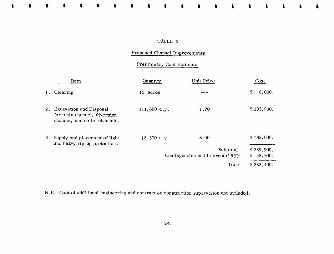
A preliminary estimate of the cost of constructing the proposed creek channel improvements is given in table 3 on the following page.
The diversion dyke and south bank dyke will be constructed from excavated gravels ?he remainder of the excavated material will be disposed of in the area south of the creek, as permitted by the Federal Department of Agriculture. * The material could be used to fill the abandoned flood channels and generally improve the appearance of the area. The Provincial Department of Recreation and Conservation owns a portion of this area for future park development. Over 100,000 c .y. of ex- cavated material will be available for the above purpose : only 9000 c .y are required for dyke construction.
The estimate assumes that some of the required
coarse cobbles and boulders a t the head of the fan and that the remainder can be obtained by quarrying the rock faces at this location,
' light' riprap will be obtained from the excavation of
No allowance has been made for replacement of the upper bridge,
* Footnote : Refer letter from Dr . D.V. Fisher (Director of the Research Station) to the Hon. W.A.C. Bennett, dated July 12, 1972.
23 .
a
0
0
'c, 0
(5
.
00" .. m
m
rl
tpr
-I
"I
..
tpr
c 0
G? I
d
I ""4
U
0
hl
H
0
0
00
5
cd e m
a,
h
I
u u 0
0
Lo co H
- I
.. H
rl
H
rl
a cd
c bo c
Q
r)
c, m
6
m' z' H
cu
m
Thurber Consultants Ltd.
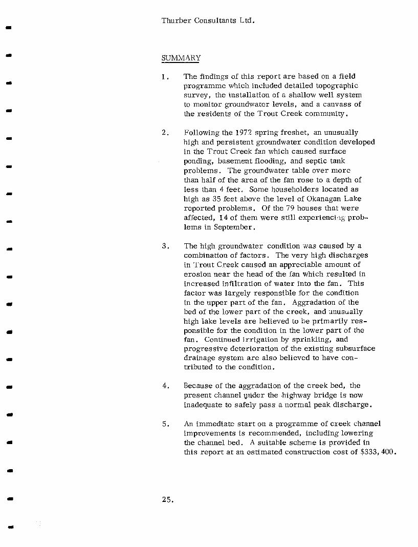
SUMMARY
1 .
2.
3 .
4 .
5 .
The findings of this report are based on a field programme which included detailed topographic survey, the installation of a shallow well system to monitor groundwater levels, and a canvass of the residents of the Trout Creek community.
Following the 1972 spring freshet, an unusually high and persistent groundwater condition developed in the Trout Creek f a n which caused surface ponding, basement flooding, and septic tank problems. The groundwater table over more than half of the area of the fan rose to a depth of less than 4 feet. Some householders located a s high a s 35 feet above the level of Okanagan Lake reported problems. Of the 79 houses that were affected, 14 of them were still experiencilrg prob- lems in September.
The high groundwater condition was caused by a combination of factors. The very high discharges in Trout Creek caused an appreciable amount of erosion near the head of the fan which resulted in increased infiltration of water into the fan. This factor was largely responsible for the condition in the upper part of the fan. Aggradation of the bed of the lower part of the creek, and anuatially high lake levels are believed to be primarily res- ponsible for the condition in the lower part of the fan. Continued irrigation by sprinkling, and progressive deterioration of the existing subsurface drainage system are also believed to have con- tributed to the condition.
Because of the aggradation of the creek bed, the present channel ynder the .highway bridge i s now inadequate to safely pass a normal peak discharge.
An immediate start on a programme of creek channel improvements is recommended, including lowering the channel bed. A suitable scheme is provided in this report at an estimated construction cost of $333,400.
25.
Thurbei:;Consultants Ltd,
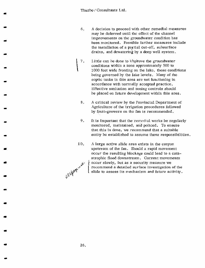
6.
\ 7 *
8.
9 .
10.
A decision to proceed with other remedial measures may be deferred until the effect of the channel improvements on the groundwater condition has been monitored. Possible further measures include the installation of a partial cut-off, subsurface drains, and dewateriig by a deep well system.
Little can be done to ihijrove the groundwater conditions within a zone approximately 500 to 1000 feet wide fronting on the lake, these conditions being governed by the lake levels. Many of the septic tanks in this area are not functioning in accordance with normally accepted practice, Effective sanitation and zoning controls should be placed on future development within this area.
A critical review by the Provincial Department of Agriculture of the irrigation procedures followed by fruit-gr;owers on the fan is recommended.
It is important that the remedial works be regularly monitored, maintained, and policed. To ensure that this is done, we recommend that a suitable entity be established to assume these responsibilities.
A large active slide area exists in the canyon upstream of the fan. Should a rapid movement occur the resulting blockage could lead to a cata- strophic flood downstream e Current movements occur slowly, but as a security measure we recommend a detailed surface investigation of the slide to assess its mechanism and future activity.
26.

4
Thurber Consultants Ltd I
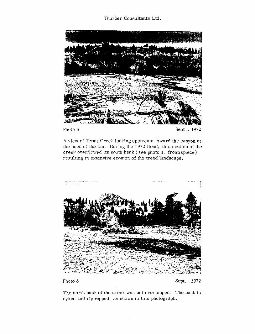
Photo 5 Sept . , 1972
A view o f Trout Creek looking upstream toward the canyon at the hea.d o f the fa.n, D:ring the 1972 flood, this section of the creek overflowed its south h m k ( see photo I , frontispiece) resulting in extensive erosion of the treed landscape.
_. - . , .. -. . ., . 2.. .
" .. . . . . I
Photo 6 Sept . , 1972
The north bank of the creek was not overtopped. The bank is dyked and r ip rapped, as shown in this photograph.

Thurber Consultants Ltd .
Ph.oto i Sept . , 1972
L4,ggradation o f the creek bed has occurred, particularly in 1972, This photograph shows the alluvium that was deposited at the mouth of the creek, when the lake level was approximate- Is- ., feet higher, It should be noted that the lake level in 1972 peaked out approximately 30 days after the creek.
Photo 8 iept . , 1972
The high groundwater level condition which developed after the flood, continued into early Fall. This resulted in the occasion- al damage to orchards, as illustrated by the dying trees in this photograph.

Thurber Consultants Ltd.
Photo 9 Sept * , 1972
Other effects of the continuing high groundwater levels are shown in p'notos 9 and 10. Photo 9 shows an attempt being made by a householder to lower the groundwater level around his house. All the householders in this area dispose of waste through individual septic tank systems. Some basements still tended to flood and required pumping in September.
Photo 10 Sept . , I972
The outflow from an installation such as that shown in photo 9 was passed, where feasible, directly into the creek.

-. I nurher ConsuitanLs Lta.
Approximately 2 miles above the head of the fan, the creek flows along the toe of the "Perpetual Slide". The slide has developed in weathered sandstones overlain by silty gravpls. The upper part of the slide is shown in this photograph. It i s 1500 feet across.
Photo 12 Nov., 1972
The "Perpetual Slide" is active, probably moving slowly and intermittently a I t ' s toe is shown in this photograph. The slide contributes silt to the creek, which is believed by some to re- su l t in a temporary 'sealing' of the creek bed in the upper part of the fan below the canyon.


Thurber Consultants Ltd.
SHALLOW OBSERVATION WELLS * , . . . . . *. . . . . , . . WATER LEVEL READINGS ( 1972)
OBS, WELL CAP DEPTH OF WATER LEVEL ( FEET) NO. ELEV.
Sept. 25 Oct. 2 Oct. 13 Oct. 30 Nov. 11
72 - 1 72fT 2 72 - 3 72 - 4 72 - 5 72 - 6 72 - 7 72 - 8 72 - 9 72 - 10 72 - I1 72 - 12 72 - 13 72 - 14 72 - 1 5 72 - 16 72 - 17 72 - 18 72 - 19 72 - 20 72 - 21 72 - 22 72 - 23 72 +24 72 - 25 72 - 26 72 - 27 72 - 28 72 - 29
. 72 - 30 72 - 31 72 - 32 72 - 33 72 - 34 72 - 35
1126.23 1126.38 1130.46 1127.75 1128,86 1127.40 1127.05 1125.52 1126.01 113P '41 1134.83 1138.69 1133.08 1135.25 1137.56 1135.19 1138.46 1136.28 1130.71 1137.20 1131.50 1131.46 1131.24 1137.48 1141 .OO 1147.78 1144.02 1143. 61 1149.35 1143.77 1134.17 1130.52 1131.39 1149.45 1151 .OS
4.4 3.3 4" 8 4.6 4.0 3.5 3.6 1 . 7 3.4 2.3 5.2 4.5 4.9 3 '7 3 . 0 2.4 3.7 2.7 0.4 3.5 7 .O 1.7 2.2 4.7 3.8 7.7 5.3 5.9
11.7 8.6 3.0 5.4 5.4 6.8 5 ,3
4.3 3.2 4.6 4.5 4.1 3.5 3.5 1.7 3.4 2.3 4.8 4.6 4 .,9 3.9 3.3 2.7 3.8
0.5 3.5 7 .O 1.7 2.1 4.8 3.9 8.0 5 '4 6 . 1
12 .o 8.8 2,8 5 , s 5.3 7.0 5 . 5
2 * 8
4.1 3.3 4.8 4.8 4.2 3.5 3.7 1.7 3! 3
4.4 4.9 5,O ..
4.1 3.5 2 ,8 4.0 2.8 0.5 3.6 6.8 1.8 2.3 5.0 4.3 8 ,5 6.0 6.6
12.7 8.7 3.3 5.7 5.1 7.6 6.3
a .4
4.4 3.6 4.8 4.8 4.2 3 -7 3.8 1 .9 3.1 2.7 4.0 5.3 5 .!J 4.. 4 3 -3 3 :o 4.4 3.0 0.7 3.8 6.6 2 .o 2.4 5.6 5.6 9.9 7 .O 7.6
13.8 8.8 3.4 5.7 5.0 9 . I 7.8
4.5 3.7 4.9" 4.9 4.3 3.8 3-9 1,9 3.1 2 .? 3.9 5.6 5.1 4.5 4.2 3.1 4.8 ' 3.3 0.8 4.0 6.8 2.1 2.5 5.9 6.2
10.8 7.2 8.2
14.5 9.1 3.5 5.8 5.1
10.1 9.0

Thurber Consultants Ltd.
continued.
SHALLOW OBWERVATION WELLS . . . . ”.. . , . . . . . . .WATER LEVEL READINGS ( 1972)
OBS. WELL CAP NO .. ELEV .
72 - 36 1153.97 72 - 37 1149.84 72 - 38 1155.86 72 - 39 1152.29 72 - 40 1155.63 72 - 41 1136.48 72 - 42 1130.76 72 - 43 1164.77 72 - 44 1167.40 72 - 45 1172.67 72 - 46 1182.38
DEPTH OF WATER LEVEL ( FEET)
Sept. 25 Oct. 2 Oct. 13 Oct. 30 Nov. 11
10.8 7.9 11.6 10.7 13.4 3.9 4.4
D To IR 0 1 1
1 1
Dry To 11.2
11.3 8.3 12.1 11 . I 14.0 4.2 4.4
DRY I t
I 1
1 1
12.0 9 .O 12.9 11.7 14.9 4.6 4.6
DRY 11
1 1
1 1
14.0 10.4 14.6(Mud) 13.0 14.8 (Mud) 5.1 4.8
DRY 1 1
11
1 1
15.0 11.3 14,9(Mud) 13.6 14.6(Mud) 5.5 5.0’
DRY 11
I,
II

rl
1
I
1
m
Y
Y
d
rl
Y
'rr
L
I Pt
TROUT CREEK GROUNDWATER STUDY DRAWN - TRACE0 D.W. S.
LOCAT I ON PLAN
I SmLE 1 : 50.000
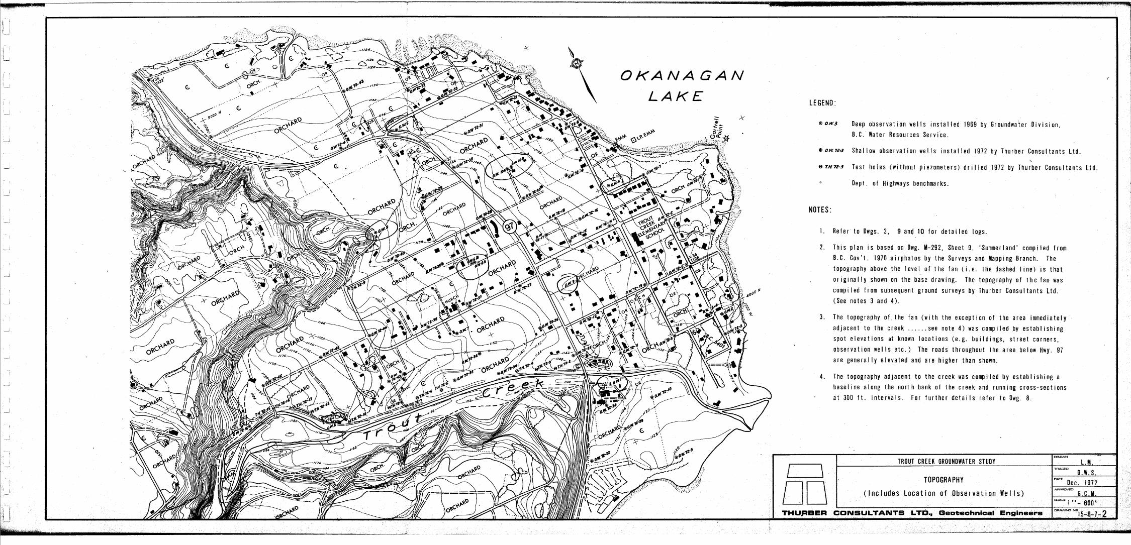
LEGEND:
0 0 . ~ 3 Deep o b s e r v a t i o n w e l l s i n s t a l l e d 1 9 6 9 b y G r o u n d w a t e r D i v i s i o n , B . C . Water Resources Serv i .ce.
@o.w72-3 S h a l l o w o b s e r v a t i o n w e l l s i n s t a l l e d 1 9 7 2 b y T h u r b e r C o n s u l t a n t
em7r-3 T e s t h o l e s ( w i t h o u t p i e z o m e t e r s ) d r i l l e d 1 9 7 2 b y T h u r b e r C o n s u ..
s L t d .
I t a n t s L t d .
Dept. of Highways benchmarks.
NOTES:
1. R e f e r to Dwgs. 3, 9 and 10 f o r d e t a i l e d l o g s .
2. T h i s p l a n i s b a s e d on Dwg. 111-292, Sheet 9 , ‘Summer land’ compi led f rom 6.C. Gov ’ t . 1970 a i rpho tos by t he Su rveys and Mapp ing B ranch . The t o p o g r a p h y a b o v e t h e l e v e l o f t h e f a n ( i . e . t h e d a s h e d l i n e ) i s t h a t o r i g i n a l l y shown on t he base d raw ing . The t opography o f t hc f an was c o m p i l e d f r o m s u b s e q u e n t g r o u n d s u r v e y s b y T h u r b e r C o n s u l t a n t s L t d . (See n o t e s 3 and 4 ) .
3. The t o p o g r a p h y o f . t h e f a n ( w i t h t h e e x c e p t i o n o f t h e a r e a i m m e d i a t e l y a d j a c e n t t o t h e c r e e k . . . . . . see n o t e 4 ) was c o m p i l e d b y e s t a b l i s h i n g s p o t e l e v a t i o n s at k n o w n l o c a t i o n s ( e . g . b u i l d i n g s , s t r e e t c o r n e r s , o b s e r v a t i o n we1 I s e t c . ) The r o a d s t h r o u g h o u t t h e a r e a b e l o w Hwy. 97 a r e g e n e r a l l y e l e v a t e d a n d a r e h i g h e r t h a n shown.
4 . The t o p o g r a p h y a d j a c e n t t o t h e c r e e k was c o m p i l e d b y e s t a b l i s h i n g a b a s e l i n e a l o n g the n o r t h b a n k o f t he c r e e k a n d r u n n i n g c r o s s - s e c t i o n s a t 300 f t . i n t e r v a l s . F o r f u r t h e r d e t a i l s r e f e r t o Dwg. 8 .
Cornpac< sundy GRAVfL
w
Very dense course.
s/Yty GRAVEL
P
,-former extent o f kume ferrace
J €.
0. wC6 //5z.4
Si/iy GRA VEL compucf c 15'
Si/fy gru ve//y CLA Y
Loose, sundy
sdi'y GRA V€L
//48.6 Ftne d f y SAND
Coume GRAVEL
/?he si/* SA NO f course GRAY&
say CLAY SAND # GRAVEL
Rusfy, fine si/fy SAND
SK€TCH SHOW/NG ORiG/N O f
DEPOSITS IN .TROUT CREEK FAN
ow3 1139.0 / / 4 A 9
StYfy CLAY
. GRAV€L Compucf stWy
Compact coarse. si / fy GRAV€L
c/ay /uyers
Luyvcd si/e GRAV€L w/Yh c/wy
I Comport coarse si/ty GRA VEL
Very dense c/ayey GRA V€L
//08.O
Loose si/fy GRA V€L
Layered course
NOTES :
\ KEY PLAN
o w / //3 7.0
Screen
Compcf fo /oose,
rusfy, course
GRAV€L und si/fy SAND
CLAY
StYfy sandy GRA VEL
Luyered course GRA V€L
und s4Wy CLAY
B/ue CLAY
Layered b/uc CLAY f SAND
0. W / O //38.9 f Co//ar €/ew I //35.9 f G. L. €/err)
StWy SAND wdh c/uy
Compacf course
sdfy GRAV€L
O M 4 /13/. 5 //z9.5 Si/ty SAND wifh
c/uy sfreuks
SYfy SAND wifh /eyers o f grove/
I Very dense, very
course c/uyey
GRA VEL
//OC 5
These w e 1 Is were i n s t a l l e d a n d l o g g e d i n 1969 b y t h e G r o u n d w a t e r D i v i s i o n o f B . C . W a t e r R e s o u r c e s S e r v i c e .
0. w2 //2 Z 5
Coarse, si/fy GRAV€L
Layers of pea GRA V€L C 16'
S i / f y SAND
Compuct w,Yh /oose-3ones, si/fy SAND. Some pebb/es
CYnd c/uy /uyefs
OKANAGAN / LAKE
I TROUT CREEK GROUNDWATER STUDY DRAWN
D.W.S. I ! \ I I "
I I nn I I / I I . \ I
GEOLOGY OF FAN
( I n c l u d e s L o g s o f D e e p O b s e r v a t i o n We1 Is) .
lmTE Oec. 1972 -0
G . C . M .
I I
I
%
%
O K A N A ’ G A N L A K E
LEGEND :
( u n s h a d e d )
NOTES
O b s e r v a t i o n Well o r T e s t H o l e
F o r m e r c o u r s e o f c r e e k
P r e d o m i n a n t l y S a n d a n d Si I t y Sand ( i .e,. > 80% Sand)
P r e d o m i n a n t l y S a n d y G r a v e l a n d C o b b l y G r a v e l ( i . e . > 20% G r a v e l )
T h i s d r a w i n g i s i n t e n d e d t o show t h e a p p r o x i m a t e d i s t r i b u t i o n o f s a n d s an.d g r a v e l s t h r o u g h o u t t h e s u r f a c e a r e a o f t h e f a n . The c I a s s i f i c a t i o n i s b a s e d o n t h e s o i I t y p e s e n c o u n t e r e d i t h e t e s t h o l e s a n d o b s e r v a t i o n w e l l s w i t h i n 10 f e e t o f t h e s u r f a c e . A “ S u b s o i I M a p ’ ’ c o v e r i n g p a r t o f t h e a r e a was p r e p a r e d b y K e l l y i n 1945 . The map was u t i l i z e d i n p r e p a r i t h i s d r a w i n g , a l t h o u g h t h e l o c a t i o n o f some o f t h e c o n t a c t s w e r e c h a n g e d t o f i t t h e o b s e r v a t i o n well d a t a . R e f e r e n c e w a s a l s o made t o a r e p o r t e n t i t l e d “ R e c o n n a i s s a n c e o n t h e r e p o r t e d h i g h w a t e r t a b l e , T r o u t C r e e k F a n ” d a t e d A u g u s t 1972 by A.N. Campbe l l , - a summer . s t u d e n t ’ e m p l o y e d b y t h e G r o u n d w a t e r D i v i s i o n .
TROUT CREEK GROUNDWATER STUOY OPAWN
0 . w . s. TRACED
”
DISTRIBUTION OF SURFACE DEPOSITS DATE
Oec. 1972
I
THURBER CONSULTANTS LTD, Geotechnical Engineers I O R A W J I N O NQ 154-7-4 i: i

NOTE
I n f o r m a t i o n was o b t a i n e d o n 176 h o u s e s . i n t h e .area. ( T h e r e a r e a p p r o x i m a t e l y 200 r e s i d e n c e s o n t h e f a n ) . O f t h e s e , 79 r e p o r t e d s u r f a c e a n d / o r g r o u n d w a t e r p r o b l e m s t h i s y e a r . The - l o c a t i o n o f t h e s e h o u s s s a r e s h o w n in r e d o n t h i s d r a w i n g .
F o r f u r t h e r d e t a i l s o n t h e n a t u r e o f p r o b l e m s d u r i n g 1972 a n d p r e v i o u s y e , r e f e r t o t h e t e x t o f t h e r e p o r t .
e
!
TROUT CREEt i GROUNOWATER STUDY O . W . S .

!
JULY 1 , 1 9 7 2 /
LEGEND: T
-2- D e p t h b e l o w s u r f a c e ( i n f e e t ) .
- //50 - E l e v a t i o n o f g r o u n d w a t e r t a b l e .
P
_ _ _ ~ "" . .~
TROUT CREEK GROUNDWATER STUDY D R A W
0. #.
GROUNDWATER TABLE TRhCED
D . W . S . Dec . 1972
( J u l y 1 a n d S e p t . 2 5 , 1 9 7 2 ) G . C . M .
THURBER CONSULTANTS LTD, Geotechnical Engineers I DRAWINS N9 15-fi-7- fi ~ ~~~~~
I-
1969 1970 1971 1972 1969 1970 1971 1972
X
w t n
1 1969 . 1970 la71 1972 1969 1970 1971 1972 1969 1970 1971 1972 1969. 1970 1971 1972 1969 1970 1971 1972
II I
I NOTES:
I . : R e f e r t o Dwg. 3 ' l o r c o l l a r e l e v a t i o n a n d
h
\ OKA NAGAN
1969 1970 1971 1972 LAK€
d, -~
I DRAWN
D.W.-$. .TROUT 'CREEK GRO.UNDWATER STUDY I - 1
'EIw.1128.~ 1 1 1 1 1 1 " " " " 1 ' " " " " " " " 1 '
~ ~ ~ ~ ~ ~ J F M A M J J A S O N D J F M A M J J A S O N D J ~ M A M J J A S D N D J F M A ~ J J A S D N D
1969 1970 1971 1972 HYDROGRAPHS OF DEEP OBSERYAT ION WELLS
. -E G.C.M. " ..
1 @6S 1970 197,l

I
, , 7YPf CA L CROSS SFCTIUNS
DiV€RSlON CHANNEL D/V€RS/ON DYK€
wasfc qrcrvc/ h
OKANAGAN
LAKE
Topography
DES I GN NOTES:
.
1. T h e d y k e s a r e t o b e c o n s t r u c t e d f r o m g r a v e l e x c a v a t e d f r o m t h e r i v e r c h a n n e l . The minimum r e q u i r e m e n t s f o r d y k e d e s i g n a r e a c r e s t w i d t h o f 12 feet, a back s l o p e o f 1 on 2 , and a c h a n n e l f a c i n g s i o p e o f 1 on 1 .5 ( w h e r e p r o t e c t e d ) o r
The ainirnum c r e s t e l e v a t i o n s a r e g i v e n o n t h e e x i s t i n g d y k e s - e x c e e d t h e s e r e q u i r e m e n t s , t h e y
3 .
4 .
Nd.1 s e c t i o n i s p r o p o s e d . T h e a r e a u p s t r e a m o f t h e i m p r o v e m e n t s ( i . e . u p s t r e a m o f S t a . 45+00) may f l o o d p e r i o d i c a l l y .
E x c a v a t e d w a s t e may be d i s p o s e d o n the s o u t h s i d e o f T r o u t C r e e k i n d e s i g n a t e d a r e a s ( e o g e i n e r o d e a a r e a s ) ,
4
1 on 3 ( w h e r e n o t p r o t e c t e d ) . p r o f i l e o n S h e e t 2. Where the a r e t o be l e f t ' ' a s i s " . n TROUT CREEK GROUNDWATER STUDY 1 0. s.
TRACED D. w. s.
nin I TROUT 'CREEK CHANNEL IMPROVEMENTS t Dec. I 1972
G.C.Y. a i n a d i s c h a r g e o f 4500c.f.s. w i t h a f r e e b o a r d 2. The c h a n n e l i s d e s i g n e d t o c o n o f 2 f e e t . WZALE Shown
THUREER CONSULTANTS &TD:*, Geotechniccsi Engineers . 1 5-6-7 - 8 DRmm Np
r

1 2 1 0
1200
1 1 9 0
N m + I I I I 1 T r- 1 I ~ -1
-IN # I I
Lo I
E W
r-- ---I-
l i n e c h a i n a g e s f e r t o shee t 1 ) PROF/L E Sfa. /5+00 fo 56+ 00
0 Q) + m
GENERAL ARRANGEMENT FOR - m .
1170
1.1 60 No channe/ /hprovcmenf + N o r t h D y k e #erm/'nafes beyond Sta. 48+23 ut St'u. 48+i'3
I
NOTES: ,I 150
w F
W LL 1 1 4 0
1'. The no rma I c h a n n e l p r o f i l e ( S e c t i o n A - A o f s h e e t I , t y p i c a l ) i s r e s u m e d 70 f e e t u p s t r e a m a n d d o w n s t r e a r n o f t he b r i d g e c e n t r e - I i n e .
2 . Ramps may be c o n s t r u c t e d i f a c c e s s t o t h e d y k e s f r o m Hwy. 97 i s d e s i r e d .
3 . P r o t e c t i o n a g a i n s t s c o u r a t t h e b r i d g e i s t o c o n s i s t o f a 3 f e e t t h i c k l a y e r o f r i p r a p . The r i p r a p s h o u l d h a v e a m i n i m u m a v e r a g e r o c k s i z e ( 0 5 0 > o f 21 ins., a n d b e w e l l - g r a d e d f r o m a m a x i m u m s i z e a p p r o x i m a t e l y e q u a l t o 1 . 5 t i m e s t h e a v e r a g e s i z e v a r y i n g d o w n t o I i n c h . The r o c k f r a g m e n t s s h o u l d b e m o r e o r l e s s e q u i d i m e n s i o n a t , b u t a n g u l a r ( p r e f e r a b l y q u a r r i e d ) a n d s o u n d .
I I I I I I I
- I I I I
45 f 00 40 + 0 0 35 + 0 0 30 + 0 0 25 + 0 0 20 + 0 0 15 + 00 55 + o o 50 + 00
z
C R E E K C H A N N E L C H A I N A G E
a, ba U .-
D L..
c
B a s e l i n e c h a i n a g e s ( r e f e r t o sheet 1 )
P R O f / L E Sfa./5+00 to -26+00 P r o p o s e d minimum c r e s f e / e v a f / o n o f North und Soufh Dykes I Rfkrop b/ankeffing Of
bed o f chunne/ exfends I I l l I 1 1 6 0 0 Ln
p3 +
1150
1 I40
1 I30
S h e e t N o . 2
TROUT CREEK GROUNDWATER STUDY D.S. D . W . S .
TRACED
I I I I I
15 + o o w o o 5 t o o 0 + o o -5 + 00 C R E E K CHANNEL CHA
-
I NAGE
10 + 0 0 - 15 + 0 0 -20 + 00 25 + 0 0 c- " I - 1 TROUT CREEK CHANNEL IMPROVEMENTS nn I
SECT/ON O N BR/DG€ & SCALE Shown
THURBER CONSULTANTS LTD., Geotechnical Engineers DRaWING NO-
15-6-7-8
. - .. . . . .


rE1e vation U28.86 a
, S A N O Loose, coarse
.
NOTES :
1 . R e f e r t o D w g . 2 f o r l o c a t i o n s
2. T h e s e o b s e r v a t i o n w e l l s w e r e i n s t a l l e d S e p t . 1972 u s i n g a t r u c k - m o u n t e d a u g e r .
3. A l l o b s e r v a t i o n w e l l s c o n t a i n 1 i n c h d i a m e t er p e r f o r a t e d i r o n p i p e . C o l l a r e l e v a t i o n s a n d d e p t h o f p i p e a r e s h o w n .
.Peof. ROO ts .
S h e e t No. 1 . . .
TROUT 'CREEK GROUNDWATER S T U D Y DRAWN
0. M. n TRACED "
L O G S OF S H A L L O W O B S E R V A T I O N W E L L S APPROVED
G . C . M .
1 THUBBER CONSULTANTS LTP., Geotechnical Engineers ImAW'"" - . 15-6-7-9 .
W e / / N P 72-30 We// dP.72-3/ We // N? .72-32
W e / / No 72-44 kle
N O T E S :
1 . R e f e r t o Dwg. 2 f o r l o c a t i o n s .
2 . T h e s e o b s e r v a t i o n w e l l s were i n s t a l l e d S e p t . 1972 u s i n g a t r u c k - m o u n t e d a u g e r .
3 . A l l o b s e r v a t i o n w e l l s c o n t a i n 1 i n c h d i a m e t e r p e r f o r a t e d i r o n p i p e . C o l l a r e l i v a t i o n s a n d d e p t h o f p i p e a r e shown.
. S h e e t No. 2
TROUT C R E E K GROUNDWATER S T U D Y DRAWN
/"-I 0. M.
TRACED "
U DATE N o v . 1 9 7 2
G.:C.M. L O G S OF S H A L L O N O B S E R V A T I O N W E L L S nPPROVED
SCALE 1 ' " 5' I THURBER CONSULTANTS LTD., Geotechnical Engineers I 15-6-7- 9 -

.. .. .- ,
.* .. .. * . ..
fist Hole fist Hole k t f fofe f l? 72-10 No 72-// Nu 72-12 .
NOTES :
1 . R e f e r t o Dwg. 2 f o r l o c a t i o n s .
2 . T h e s e t e s t h o l e s w e r e d r i I l e d S e p t . 1 9 7 2 u s i n g a t r u c k - m o u n t e d a u g e r .
. . .I .I
T R O U T C R E E K G R O U N D W A T E R S T U D Y DRAWN
0. M. TRACED
"
N o v . 1972 LOGS OF T E S T H O L E S
I I

I
I


