TIA STANDARD TIA-916 Recommended Minimum Performance Specification for TIA/EIA/IS-801-1 Spread Spectrum Mobile Stations TIA-916 APRIL 2002 TELECOMMUNICATIONS INDUSTRY ASSOCIATION The Telecommunications Industry Association represents the communications sector of Reproduced by IHS under license with EIA GMT. No reproduction or networking permitted.;NFS|2|never|69|This copy reproduced from an authorized download of a NSF standard by %c on %d. No further --`,`,``,,`,,,`,,,``,`,-`-`,,`,,`,`,,`---
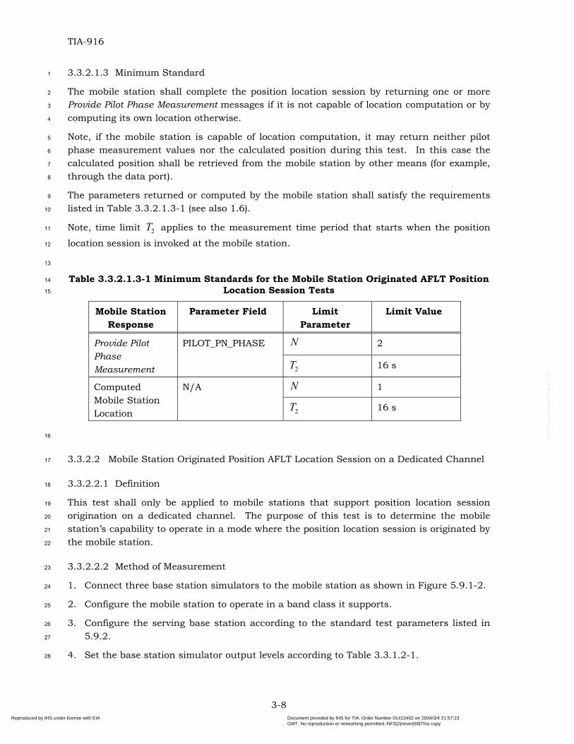
Transcript
TIA STANDARD
TIA
-916
Recommended Minimum Performance Specification for TIA/EIA/IS-801-1 Spread Spectrum Mobile Stations TIA-916 APRIL 2002
TELECOMMUNICATIONS INDUSTRY ASSOCIATION
The Telecommunications Industry Association represents the communications sector of
Reproduced by IHS under license with EIA
Document provided by IHS for TIA, Order Number 01413402 on 2004/3/4 21:57:23GMT. No reproduction or networking permitted.;NFS|2|never|69|This copyreproduced from an authorized download of a NSF standard by %c on %d. No further
--`,`,``,,`,,,`,,,``,`,-`-`,,`,,`,`,,`---
NOTICE TIA/EIA Engineering Standards and Publications are designed to serve the public interest through eliminating misunderstandings between manufacturers and purchasers, facilitating interchangeability and improvement of products, and assisting the purchaser in selecting and obtaining with minimum delay the proper product for his particular need. Existence of such Standards and Publications shall not in any respect preclude any member or nonmember of TIA/EIA from manufacturing or selling products not conforming to such Standards and Publications, nor shall the existence of such Standards and Publications preclude their voluntary use by those other than TIA/EIA members, whether the standard is to be used either domestically or internationally. Standards and Publications are adopted by TIA/EIA in accordance with the American National Standards Institute (ANSI) patent policy. By such action, TIA/EIA does not assume any liability to any patent owner, nor does it assume any obligation whatever to parties adopting the Standard or Publication.
TIA STANDARDS
TIA Standards contain information deemed to be of technical value to the industry, and are published at the request of the originating Committee without necessarily following the rigorous public review and resolution of comments which is a procedural part of the development of a TIA/EIA Standard. TIA Standards should be reviewed on an annual basis by the formulating Committee and a decision made on whether to proceed to develop a TIA/EIA Standard on this subject. TIA Standards must be cancelled by the Committee and removed from the TIA/EIA Standards Catalog before the end of their third year of existence. Publication of this TIA Standard for trial use and comment has been approved by the Telecommunications Industry Association. Distribution of this TIA Standard for comment shall not continue beyond 60 months from the date of publication. It is expected that following this 36 month period, this TIA Standard, revised as necessary, will be submitted to the American National Standards Institute for approval as an American National Standard. Suggestions for revision should be directed to: Standards & Technology Department, Telecommunications Industry Association, 2500 Wilson Boulevard, Arlington, VA 22201 U.S.A. (From Project No. 3-0058, formulated under the cognizance of the TIA TR-45.5 Subcommittee on Spread Spectrum Digital Technology.)
Published by �TELECOMMUNICATIONS INDUSTRY ASSOCIATION 2002 Standards & Technology Department 2500 Wilson Boulevard Arlington, VA 22201 U.S.A. PRICE: Please refer to current Catalog of
EIA ELECTRONIC INDUSTRIES ALLIANCE STANDARDS and ENGINEERING PUBLICATIONS or call Global Engineering Documents, USA and Canada
(1-800-854-7179) International (303-397-7956) All rights reserved Printed in U.S.A.
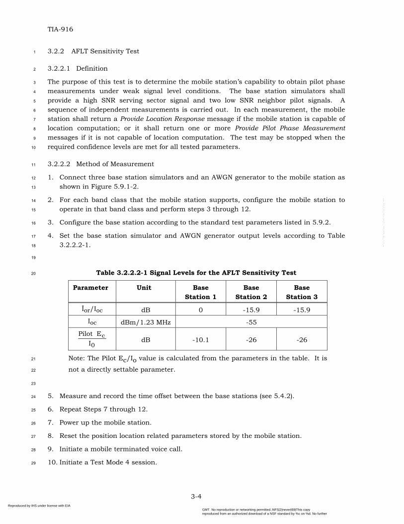
Reproduced by IHS under license with EIA
Document provided by IHS for TIA, Order Number 01413402 on 2004/3/4 21:57:23GMT. No reproduction or networking permitted.;NFS|2|never|69|This copyreproduced from an authorized download of a NSF standard by %c on %d. No further
--`,`,``,,`,,,`,,,``,`,-`-`,,`,,`,`,,`---
PLEASE! DON'T VIOLATE THE LAW! This document is copyrighted by the TIA and may not be reproduced without permission. Organizations may obtain permission to reproduce a limited number of copies through entering into a license agreement. For information, contact: Global Engineering Documents 15 Inverness Way East Englewood, CO 80112-5704 U.S.A. or call U.S.A. and Canada 1-800-854-7179, International (303) 397-7956
Reproduced by IHS under license with EIA
Document provided by IHS for TIA, Order Number 01413402 on 2004/3/4 21:57:23GMT. No reproduction or networking permitted.;NFS|2|never|69|This copyreproduced from an authorized download of a NSF standard by %c on %d. No further
--`,`,``,,`,,,`,,,``,`,-`-`,,`,,`,`,,`---
NOTICE OF DISCLAIMER AND LIMITATION OF LIABILITY
The document to which this Notice is affixed has been prepared by one or more Engineering Committees of the Telecommunications Industry Association (“TIA”). TIA is not the author of the document contents, but publishes and claims copyright to the document pursuant to licenses and permission granted by the authors of the contents.
TIA Engineering Committees are expected to conduct their affairs in accordance with the TIA Engineering Manual (“Manual”), the current and predecessor versions of which are available at http://www.tiaonline.org/standards/sfg/engineering_manual.cfm. TIA’s function is to administer the process, but not the content, of document preparation in accordance with the Manual and, when appropriate, the policies and procedures of the American National Standards Institute (“ANSI”).
THE USE OR PRACTICE OF CONTENTS OF THIS DOCUMENT MAY INVOLVE THE USE OF INTELLECTUAL PROPERTY RIGHTS (“IPR”), INCLUDING PENDING OR ISSUED PATENTS, OR COPYRIGHTS, OWNED BY ONE OR MORE PARTIES. TIA MAKES NO SEARCH OR INVESTIGATION FOR IPR. WHEN IPR CONSISTING OF PATENTS AND PUBLISHED PATENT APPLICATIONS ARE CLAIMED AND CALLED TO TIA’S ATTENTION, A STATEMENT FROM THE HOLDER THEREOF IS REQUESTED, ALL IN ACCORDANCE WITH THE MANUAL. TIA TAKES NO POSITION WITH REFERENCE TO, AND DISCLAIMS ANY OBLIGATION TO INVESTIGATE OR INQUIRE INTO, THE SCOPE OR VALIDITY OF ANY CLAIMS OF IPR.
ALL WARRANTIES, EXPRESS OR IMPLIED, ARE DISCLAIMED, INCLUDING WITHOUT LIMITATION, ANY AND ALL WARRANTIES CONCERNING THE ACCURACY OF THE CONTENTS, ITS FITNESS OR APPROPRIATENESS FOR A PARTICULAR PURPOSE OR USE, ITS MERCHANTABILITY AND ITS NON-INFRINGEMENT OF ANY THIRD PARTY’S INTELLECTUAL PROPERTY RIGHTS. TIA EXPRESSLY DISCLAIMS ANY AND ALL RESPONSIBILITIES FOR THE ACCURACY OF THE CONTENTS AND MAKES NO REPRESENTATIONS OR WARRANTIES REGARDING THE CONTENT’S COMPLIANCE WITH ANY APPLICABLE STATUTE, RULE OR REGULATION.
TIA SHALL NOT BE LIABLE FOR ANY AND ALL DAMAGES, DIRECT OR INDIRECT, ARISING FROM OR RELATING TO ANY USE OF THE CONTENTS CONTAINED HEREIN, INCLUDING WITHOUT LIMITATION ANY AND ALL INDIRECT, SPECIAL, INCIDENTAL OR CONSEQUENTIAL DAMAGES (INCLUDING DAMAGES FOR LOSS OF BUSINESS, LOSS OF PROFITS, LITIGATION, OR THE LIKE), WHETHER BASED UPON BREACH OF CONTRACT, BREACH OF WARRANTY, TORT (INCLUDING NEGLIGENCE), PRODUCT LIABILITY OR OTHERWISE, EVEN IF ADVISED OF THE POSSIBILITY OF SUCH DAMAGES. THE FOREGOING NEGATION OF DAMAGES IS A FUNDAMENTAL ELEMENT OF THE USE OF THE CONTENTS HEREOF, AND THESE CONTENTS WOULD NOT BE PUBLISHED BY TIA WITHOUT SUCH LIMITATIONS.
Reproduced by IHS under license with EIA
Document provided by IHS for TIA, Order Number 01413402 on 2004/3/4 21:57:23GMT. No reproduction or networking permitted.;NFS|2|never|69|This copyreproduced from an authorized download of a NSF standard by %c on %d. No further
2.1.1.2.2 Method of Measurement .................................................................... 2-4
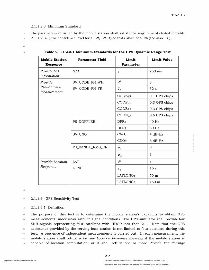
2.1.1.2.3 Minimum Standard ........................................................................... 2-5
i Reproduced by IHS under license with EIA
Document provided by IHS for TIA, Order Number 01413402 on 2004/3/4 21:57:23GMT. No reproduction or networking permitted.;NFS|2|never|69|This copyreproduced from an authorized download of a NSF standard by %c on %d. No further
--`,`,``,,`,,,`,,,``,`,-`-`,,`,,`,`,,`---
TIA-916
CONTENTS
2.1.1.3 GPS Sensitivity Test ................................................................................2-5 1
2.2.1.2 Method of Measurement ........................................................................2-11
2.2.1.3 Minimum Standard ...............................................................................2-12
2.2.2 Mobile Station Originated GPS Position Location Session Test ......................2-13
2.2.2.1 Mobile Station Originated GPS Position Location Session on the Access Channel............................................................................................................2-13
2.2.2.2 Mobile Station Originated GPS Position Location Session on a Dedicated Channel............................................................................................................2-14
Document provided by IHS for TIA, Order Number 01413402 on 2004/3/4 21:57:23GMT. No reproduction or networking permitted.;NFS|2|never|69|This copyreproduced from an authorized download of a NSF standard by %c on %d. No further
--`,`,``,,`,,,`,,,``,`,-`-`,,`,,`,`,,`---
TIA-916
CONTENTS
3.2.1 AFLT Accuracy Test ...................................................................................... 3-2 1
3.3.2 Mobile Station Originated AFLT Position Location Session Test ...................... 3-7
3.3.2.1 Mobile Station Originated AFLT Position Location Session on the Access Channel ............................................................................................................. 3-7
3.3.2.1.2 Method of Measurement .................................................................... 3-7
3.3.2.1.3 Minimum Standard ........................................................................... 3-8
3.3.2.2 Mobile Station Originated Position AFLT Location Session on a Dedicated Channel ............................................................................................................. 3-8
4.2.2 Two Base Stations + One Satellite Hybrid Test............................................... 4-3
iii Reproduced by IHS under license with EIA
Document provided by IHS for TIA, Order Number 01413402 on 2004/3/4 21:57:23GMT. No reproduction or networking permitted.;NFS|2|never|69|This copyreproduced from an authorized download of a NSF standard by %c on %d. No further
5.8.2 Position Determination Data Message Call Flows .............................................5-9
5.9 Functional System Set-ups ...............................................................................5-13
iv Reproduced by IHS under license with EIA
Document provided by IHS for TIA, Order Number 01413402 on 2004/3/4 21:57:23GMT. No reproduction or networking permitted.;NFS|2|never|69|This copyreproduced from an authorized download of a NSF standard by %c on %d. No further
A.3 Method of Determining the PDE Simulator Response Values ............................. A-7
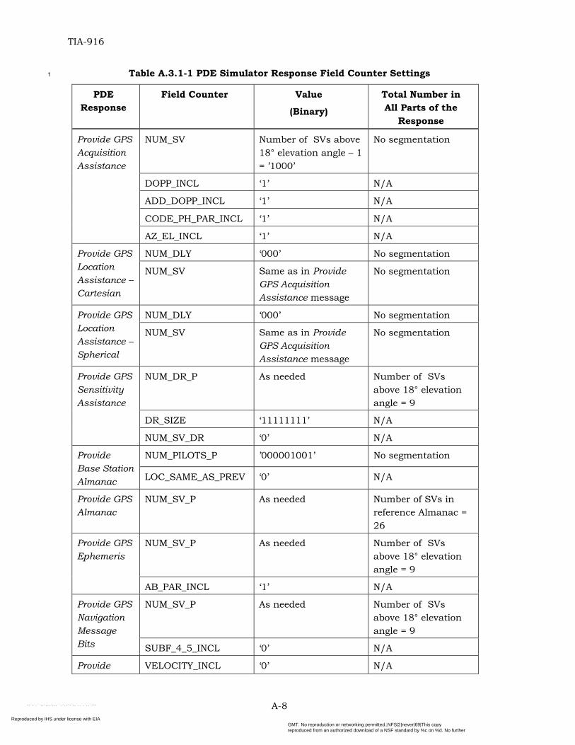
A.3.1 Setting of PDE Simulator Response Field Counters ...................................... A-7
A.3.2 Calculating of PDE Simulator Numerical Parameter Values.......................... A-9
A.3.3 Setting of PDE Simulator Response Information Parameters ........................ A-9
A.3.4 Setting of PDE Simulator Request Information Parameters......................... A-10
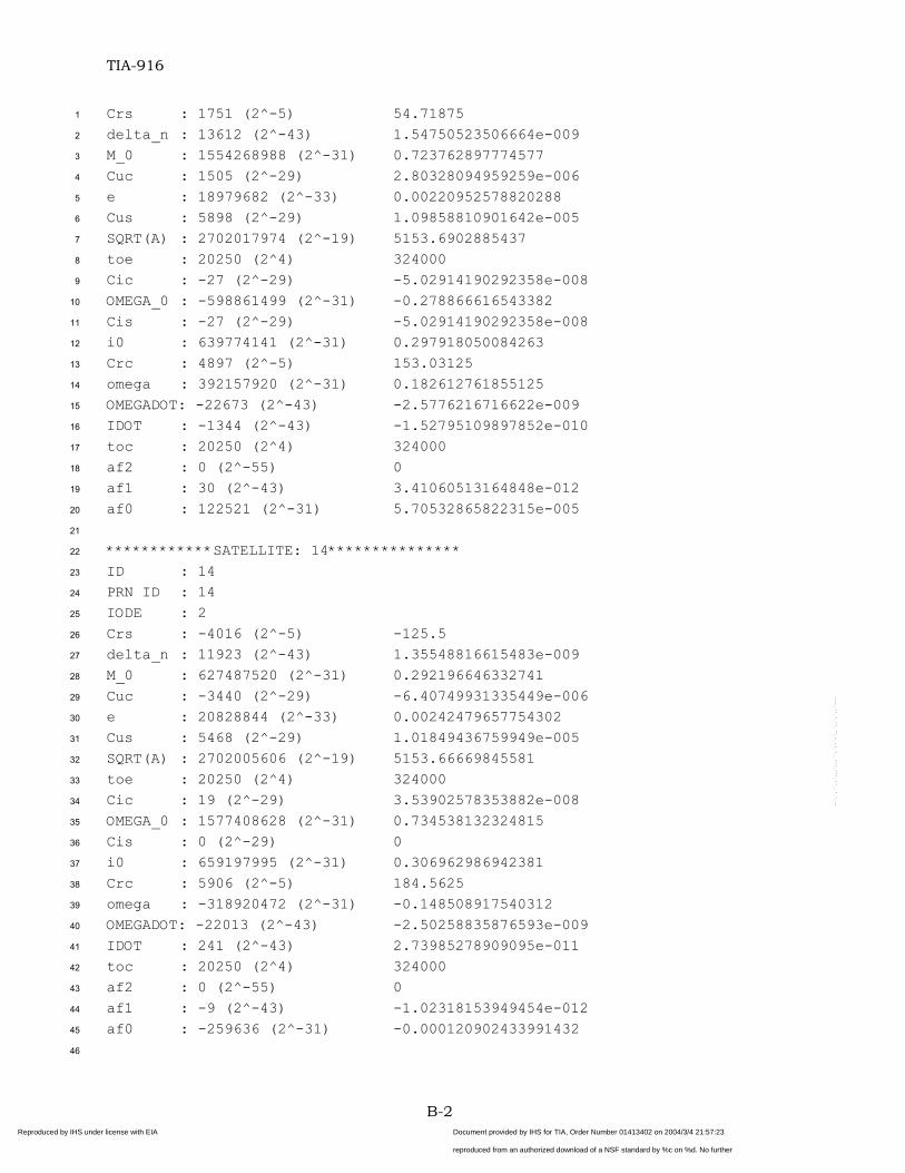
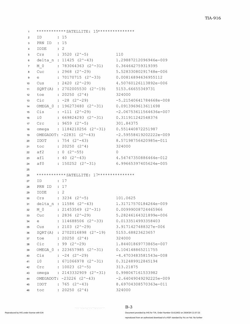
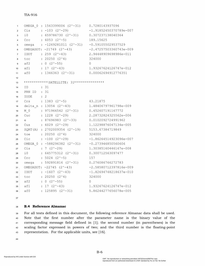
Annex B – REFERENCE GPS NAVIGATION DATA, SYSTEM TIME AND USER LOCATION .... .......................................................................................................................... B-1
Annex C – METHOD OF STATISTICAL CONFIDENCE DETERMINATION ....................... C-1
C.1 Description of the Confidence Determination Method ........................................ C-1
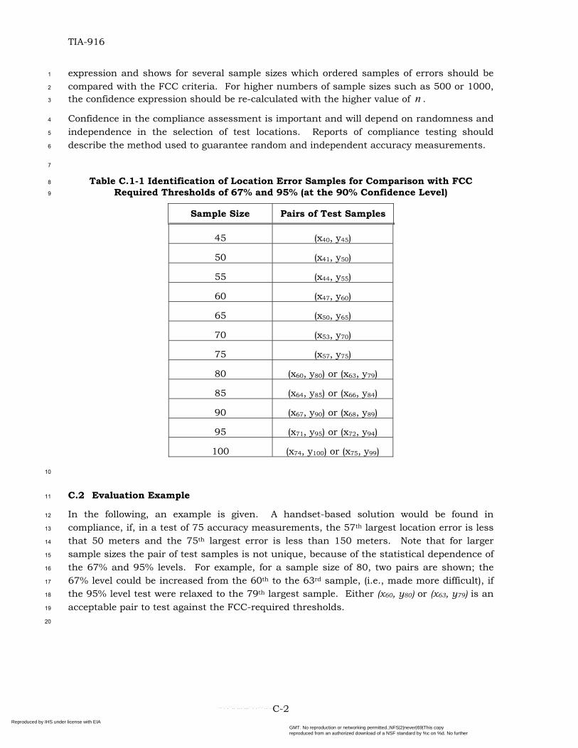
C.2 Evaluation Example ......................................................................................... C-2
Annex D PDE SIMULATOR RESPONSE MESSAGES ..................................................... D-1
v Reproduced by IHS under license with EIA
Document provided by IHS for TIA, Order Number 01413402 on 2004/3/4 21:57:23GMT. No reproduction or networking permitted.;NFS|2|never|69|This copyreproduced from an authorized download of a NSF standard by %c on %d. No further
--`,`,``,,`,,,`,,,``,`,-`-`,,`,,`,`,,`---
TIA-916
FIGURES
Figure 5.8.2-1 Example Successful Call Flow for Test Modes 1 and 2.............................5-11 1
2
3
4
5
6
7
8
9
Figure 5.8.2-2 Example Successful Call Flow for Test Modes 3 and 4, with Mobile Station that is Capable of Location Calculation ......................................................................5-12
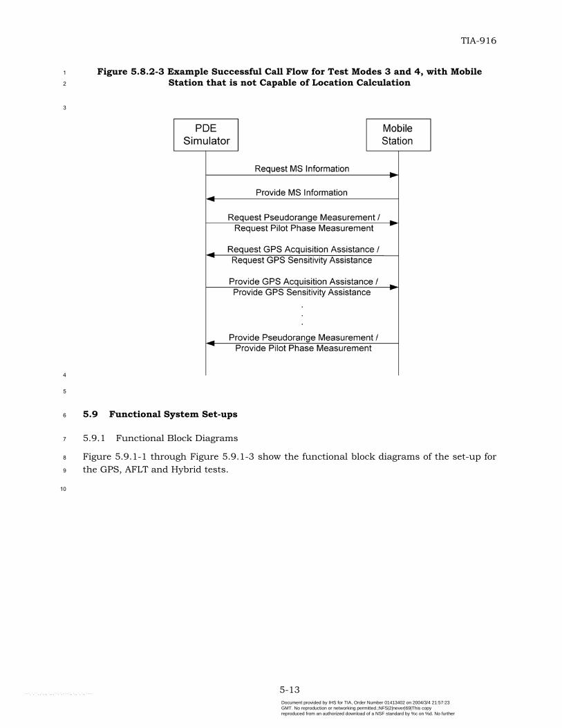
Figure 5.8.2-3 Example Successful Call Flow for Test Modes 3 and 4, with Mobile Station that is not Capable of Location Calculation ................................................................5-13
Figure 5.9.1-1 Functional Set-up for GPS Tests ............................................................5-14
Figure 5.9.1-2 Functional Set-up for AFLT Tests ...........................................................5-15
Figure 5.9.1-3 Functional Set-up for Hybrid Tests.........................................................5-16
vi Reproduced by IHS under license with EIA
Document provided by IHS for TIA, Order Number 01413402 on 2004/3/4 21:57:23GMT. No reproduction or networking permitted.;NFS|2|never|69|This copyreproduced from an authorized download of a NSF standard by %c on %d. No further
--`,`,``,,`,,,`,,,``,`,-`-`,,`,,`,`,,`---
TIA-916
TABLES
Table 1.6-1 Summary of Test Evaluation Parameters.................................................... 1-11 1
2
3
4
5
6
7
8
9
10
11
12
13
14
15
16
17
18
19
20
21
22
23
24
25
26
27
28
29
30
31
32
33
34
Table 1.6.2.1.1-1 Returned Parameter Fields and Corresponding Error Indications ....... 1-15
Table 1.6.2.2-1 Returned RMS Error Estimate Parameter Fields and Corresponding Error Indications ............................................................................................................. 1-19
Table 2.1.1.1.2-1 Satellite Signal Levels for the GPS Accuracy Test ................................. 2-2
Table 2.1.1.1.3-1 Minimum Standards for the GPS Accuracy Test................................... 2-3
Table 2.1.1.2.2-1 Satellite Signal Levels for the GPS Dynamic Range Test ....................... 2-4
Table 2.1.1.2.3-1 Minimum Standards for the GPS Dynamic Range Test......................... 2-5
Table 2.1.1.3.2-1 Satellite Signal Levels for the GPS Sensitivity Test ............................... 2-6
Table 2.1.1.3.3-1 Minimum Standards for the GPS Sensitivity Test................................. 2-7
Table 2.1.1.4.2-1 Satellite Signal Levels for the GPS Multipath Accuracy Test ................. 2-8
Table 2.1.1.4.3-1 Minimum Standards for the GPS Multipath Accuracy Test ................... 2-9
Table 2.1.2.1.2-1 Satellite Signal Levels for the Moving Scenario GPS Accuracy Test ..... 2-10
Table 2.1.2.1.3-1 Minimum Standards for the Moving Scenario GPS Accuracy Test ....... 2-11
Table 2.2.1.2-1 Satellite Signal Levels for the Protocol Tests ......................................... 2-12
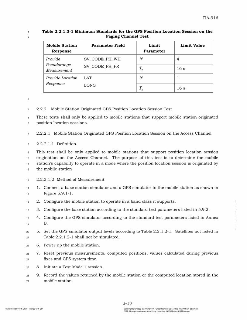
Table 2.2.1.3-1 Minimum Standards for the GPS Position Location Session on the Paging Channel Test ............................................................................................................ 2-13
Table 2.2.2.1.3-1 Minimum Standards for the Mobile Station Originated GPS Position Location Session Tests.............................................................................................. 2-14
Table 3.2.1.2-1 Signal Levels for the AFLT Accuracy Test................................................ 3-2
Table 3.2.1.3-1 Minimum Standards for the AFLT Accuracy Test .................................... 3-3
Table 3.2.2.2-1 Signal Levels for the AFLT Sensitivity Test.............................................. 3-4
Table 3.2.2.3-1 Minimum Standards for the AFLT Sensitivity Test .................................. 3-5
Table 3.3.1.2-1 Signal Levels for the AFLT Protocol Tests................................................ 3-6
Table 3.3.1.3-1 Minimum Standards for the AFLT Position Location Session on the Paging Channel Test .............................................................................................................. 3-7
Table 3.3.2.1.3-1 Minimum Standards for the Mobile Station Originated AFLT Position Location Session Tests................................................................................................ 3-8
Table 4.2.1.2-1 Satellite Signal Levels for the One Base Station + Three Satellites Hybrid Test ............................................................................................................... 4-2
Table 4.2.1.3-1 Minimum Standards for the One Base Station + Three Satellites Hybrid Test ............................................................................................................... 4-3
Table 4.2.2.2-1 Base Station Signal Levels for the Two Base Stations + One Satellite Hybrid Test ............................................................................................................... 4-4
vii Reproduced by IHS under license with EIA
Document provided by IHS for TIA, Order Number 01413402 on 2004/3/4 21:57:23GMT. No reproduction or networking permitted.;NFS|2|never|69|This copyreproduced from an authorized download of a NSF standard by %c on %d. No further
--`,`,``,,`,,,`,,,``,`,-`-`,,`,,`,`,,`---
TIA-916
TABLES
Table 4.2.2.2-2 Satellite Signal Level for the Two Base Stations + One Satellite Hybrid Test . .............................................................................................................. 4-4
1
2
3
4
5
6
7
8
9
10
11
12
13
14
15
16
17
18
19
20
21
22
23
24
25
26
27
Table 4.2.2.3-1 Minimum Standards for the Two Base Stations + One Satellite Hybrid Test . .............................................................................................................. 4-5
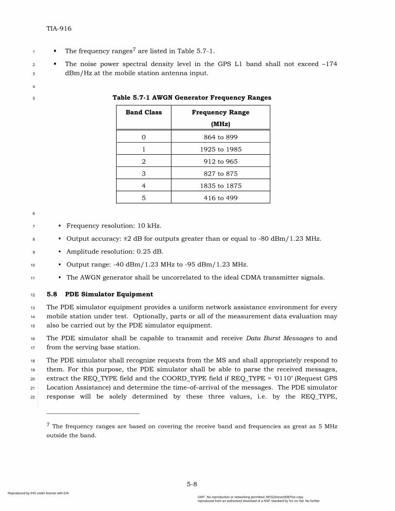
Table 5.7-1 AWGN Generator Frequency Ranges ............................................................ 5-8
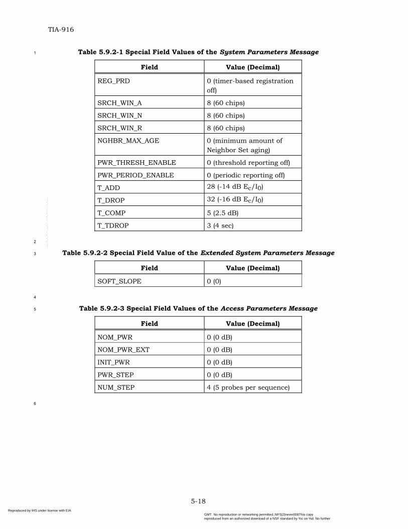
Table 5.9.2-1 Special Field Values of the System Parameters Message............................5-18
Table 5.9.2-2 Special Field Value of the Extended System Parameters Message ..............5-18
Table 5.9.2-3 Special Field Values of the Access Parameters Message ............................5-18
Table 5.9.2-4 Special Field Values of the General Neighbor List Message for the Serving Base Station .............................................................................................................5-19
Table 5.9.2-5 Time Limit and Constant Values..............................................................5-20
Table A.1.2-1 Position Determination Data Message Format for Test Modes 1 and 2 ......... A-1
Table A.1.2-2 Position Determination Data Message Format for Test Modes 3 and 4, with a Mobile Station that is Capable of Position Calculation ................................................. A-2
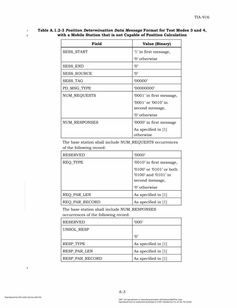
Table A.1.2-3 Position Determination Data Message Format for Test Modes 3 and 4, with a Mobile Station that is not Capable of Position Calculation ........................................... A-3
Table C.1-1 Identification of Location Error Samples for Comparison with FCC Required Thresholds of 67% and 95% (at the 90% Confidence Level) .......................................... C-2
Table D-1 Pilot PN Offset and BASE_ID Assignment Used in the PDE Simulator Response Messages ..............................................................................................................D-1
viii Reproduced by IHS under license with EIA
Document provided by IHS for TIA, Order Number 01413402 on 2004/3/4 21:57:23GMT. No reproduction or networking permitted.;NFS|2|never|69|This copyreproduced from an authorized download of a NSF standard by %c on %d. No further
--`,`,``,,`,,,`,,,``,`,-`-`,,`,,`,`,,`---
TIA-916
NOTES
1. This Standard uses the following verbal forms: “Shall” and “shall not” identify requirements to be followed strictly to conform to the Standard and from which no deviation is permitted. “Should” and “should not” indicate that one of several possibilities is recommended as being particularly suitable, without mentioning or excluding others; that a certain course of action is preferred but not necessarily required; or that (in the negative form) a certain possibility or course of action is discouraged but not prohibited. “May” and “need not” indicate a course of action permissible within the limits of the Standard. “Can” and “cannot” are used for statements of possibility and capability, whether material, physical, or causal.
1
2
3
4
5
6
7
8
9
10
11
12
13
14
15
16
17
18
19
20
21
22
23
24
25
26
27
28
29
30
31
32
33
34
35
36
37
38
39
2. There are four Annexes in this Standard. Annexes A, B, C and D are normative and are considered part of this Standard. Annex D contains a data file attachment that is normative and is considered part of this Standard.
3. The terms “location” and “position” are used interchangeably throughout this document. In this respect the definition of the term differs from the historic use of location in wireless systems to identify the mobile’s current serving system.
4. Those wishing to deploy systems compliant with this Standard should also be compliant with Parts 15, 22, 24, and 27 of [18] and with the applicable rules and regulations of local administrations. �
5. Those wishing to deploy systems in the United States should also take notice of the requirement to be compliant with Federal Communications Commission (FCC) Rulings on 911 Emergency Services. Meeting the requirements contained in this Standard does not guarantee compliance with the FCC requirements listed in [19]. �
6. The operation and messages specified in [1] apply to what is usually known as handset-based position location method. The testing of network-based methods is beyond the scope of this Standard.
7. Footnotes appear at various points in this Standard to elaborate and to further clarify items discussed in the body of the Standard.
8. Unless indicated otherwise, this document presents numbers in decimal form. Binary numbers are distinguished in the text by the use of single quotation marks.
9. The following operators define mathematical operations:
* indicates complex conjugation. � indicates a member of the set.
�x� indicates the largest integer less than or equal to x: �1.1� = 1, �1.0� = 1.
�x� indicates the smallest integer greater or equal to x: �1.1� = 2, �2.0� = 2. |x| indicates the absolute value of x: |-17|=17, |17|=17.
ix Reproduced by IHS under license with EIA
Document provided by IHS for TIA, Order Number 01413402 on 2004/3/4 21:57:23GMT. No reproduction or networking permitted.;NFS|2|never|69|This copyreproduced from an authorized download of a NSF standard by %c on %d. No further
--`,`,``,,`,,,`,,,``,`,-`-`,,`,,`,`,,`---
TIA-916
FOREWORD
� indicates exclusive OR (modulo-2 addition). 1
2
3
4
min (x, y) indicates the minimum of x and y.
max (x, y) indicates the maximum of x and y.
x mod y indicates the remainder after dividing x by y: x mod y = x - (y ����x/y�).
� �xRe indicates the real part of x. 5
� �xIm indicates the imaginary part of x. 6
7
8
9
10
11
12
13
14
15
16
17
18
19
20
21
22
23
24
25
26
27
28
29
30
31
32
33
34
35
36
37
38
39
9. This Standard supports testing of mobile stations compliant with [1].
10. This Standard supports testing of mobile stations that meet the minimum standards specified in [5].
11. This Standard tests only the position location functionality of a mobile station. Testing interoperation with other services, such as voice, data or SMS, is beyond the scope of this document.
12. This Standard does not support testing mobile station cold start time to first fix requirements.
13. References in this document are to TIA/EIA-95-B. This Standard is equally applicable to TIA/EIA/IS-2000 and TIA/EIA/IS-2000-A. Except where explicit references are made to TIA/EIA/IS-2000, the reference to TIA/EIA-95-B can be converted directly to TIA/EIA/IS-2000 and TIA/EIA/IS-2000-A usage.
14. The terms “base station” and “base station simulator” are used interchangeably throughout this document, reflecting the fact that either type of equipment may be used as long as all test equipment requirements given in this Standard are satisfied.
15. Some tests in this revision specify using a physical CDMA channel that is not mandatory for IS-2000-A mobile stations. If the mobile station does not support a specified physical channel, then the equivalent IS-2000-A-only physical channel should be used instead. Specifically, the Broadcast Control Channel and Forward Command Control Channel should be used in place of the Paging Channel, the Enhanced Access Channel should be used in place of the Access Channel, and the Dedicated Control Channel should be used in place of the Traffic (Fundamental) channel.
16. For the test parameter tables, Îor is specified in terms of power spectral density in a Spreading Rate 1 bandwidth. For testing applicable to Spreading Rate 3, the total received power in a Spreading Rate 3 bandwidth is effectively 5 dB higher.
17. Wherever this document refers to CDMA System time in frames, it is taken to mean an integer value T such that: T = �t/0.02�,�where t represents System Time in seconds.
18. The tests will be performed using modulated L1 carriers; however, the specification of the signal levels is based upon an unmodulated L1 carrier, referenced to the mobile station antenna input.
x Reproduced by IHS under license with EIA
Document provided by IHS for TIA, Order Number 01413402 on 2004/3/4 21:57:23GMT. No reproduction or networking permitted.;NFS|2|never|69|This copyreproduced from an authorized download of a NSF standard by %c on %d. No further
--`,`,``,,`,,,`,,,``,`,-`-`,,`,,`,`,,`---
TIA-916
REFERENCES
The following Standards contain provisions that, through reference in this text, constitute provisions of this Standard. At the time of publication, the editions indicated were valid. All Standards are subject to revision, and parties to agreements based on this Standard are encouraged to investigate the possibility of applying the most recent editions of the Standards indicated below. ANSI and TIA maintain registers of currently valid national Standards published by them.
1
2
3
4
5
6
7
8
xiReproduced by IHS under license with EIA
Document provided by IHS for TIA, Order Number 01413402 on 2004/3/4 21:57:23GMT. No reproduction or networking permitted.;NFS|2|never|69|This copyreproduced from an authorized download of a NSF standard by %c on %d. No further
--`,`,``,,`,,,`,,,``,`,-`-`,,`,,`,`,,`---
TIA-916
REFERENCES
1. TIA/EIA/IS-801-1, Position Determination Service Standard for Dual-Mode Spread Spectrum Systems, February 2001.
1
2
3
4
5
6
7
8
9
10
11
12
13
14
15
16
17
18
19
20
21
22
23
24
25
26
27
28
29
30
31
32
33
34
35
36
37
2. J-STD-036, Enhanced Wireless 9-1-1 Phase 2, June 2000.
3. TSB-100, Wireless Network Reference Model, July 1988.
4. TIA/EIA-97-D, Recommended Minimum Performance Standards for cdma2000 Spread Spectrum Base Stations, April 2001.
5. TIA/EIA-98-D, Recommended Minimum Performance Standard for cdma2000 Spread Spectrum Mobile Stations, April 2001.
6. EIA/IS-19-B, Recommended Minimum Standards for 800-MHz Cellular Subscriber Units, June 1988.
7. TIA/EIA/IS-95-B, Mobile Station-Base Station Compatibility Standard for Dual-Mode Spread Spectrum Systems, March 1999.
8. TIA/EIA/IS-2000.2-A-2, Physical Layer Standard for cdma2000 Spread Spectrum Systems, February 2002.
9. TIA/EIA/IS-2000.4-A-2, Signaling Link Access Control (LAC) Standard for cdma2000 Spread Spectrum Systems, February 2002.
10. TIA/EIA/IS-2000.5-A-2, Upper Layer (Layer 3) Signaling Standard for cdma2000 Spread Spectrum Systems, February 2002.
11. TIA/EIA/IS-2000.6-A-2, Analog Signaling Standard for cdma2000 Spread Spectrum Systems, July 1999.
12. TIA/EIA/TSB58-E, Administration of Parameter Value Assignments for TIA/EIA Spread Spectrum Standards, January 2002.
13. TIA/EIA/IS-858, Test Data Service Option (TDSO) for cdma2000 Spread Spectrum Systems, March 2001.
14. TIA/EIA/IS-857, Markov Service Option (MSO) for cdma2000 Spread Spectrum Systems, March 2001.
15. TIA/EIA/IS-126-D, Loopback Service Options (LSO) for cdma2000 Spread Spectrum Systems, November 2000.
16. ICD-GPS-200C, Navstar GPS Space Segment / Navigation User Interface, September 1997.
17. DMA TR 8350.2, Defense Mapping Agency Publication, September 1987.
18. CFR Title 47, Code of Federal Regulations, October 1999.
19. FCC 00-326, CC Docket No. 94-102, Fourth Memorandum Opinion and Order in the Matter of Revision of the Commission’s Rules to Ensure Compatibility with Enhanced 911 Emergency Calling Systems, September 2000.
20. FCC OET Bulletin No. 71, Guidelines for Testing and Verifying the Accuracy of Wireless E911 Location Systems, April 2000.
xiiReproduced by IHS under license with EIA
Document provided by IHS for TIA, Order Number 01413402 on 2004/3/4 21:57:23GMT. No reproduction or networking permitted.;NFS|2|never|69|This copyreproduced from an authorized download of a NSF standard by %c on %d. No further
--`,`,``,,`,,,`,,,``,`,-`-`,,`,,`,`,,`---
TIA-916
REFERENCES
21. GPS Navstar, Global Positioning System Standard Positioning Service Signal Specification, June 1995.
1
2
3
xiiiReproduced by IHS under license with EIA
Document provided by IHS for TIA, Order Number 01413402 on 2004/3/4 21:57:23GMT. No reproduction or networking permitted.;NFS|2|never|69|This copyreproduced from an authorized download of a NSF standard by %c on %d. No further
--`,`,``,,`,,,`,,,``,`,-`-`,,`,,`,`,,`---
Reproduced by IHS under license with EIA
Document provided by IHS for TIA, Order Number 01413402 on 2004/3/4 21:57:23GMT. No reproduction or networking permitted.;NFS|2|never|69|This copyreproduced from an authorized download of a NSF standard by %c on %d. No further
--`,`,``,,`,,,`,,,``,`,-`-`,,`,,`,`,,`---
TIA-916
1 INTRODUCTION 1
2
3
4
5
6
7
8
9
10
11
1.1 Scope
This Standard details definitions, methods of measurement, and minimum performance characteristics for Position Location Capable Code Division Multiple Access (CDMA) mobile stations. This Standard shares the purpose of [1] (and subsequent revisions thereof) by ensuring that a mobile station’s location can be determined in any wireless system that meets the compatibility requirements of [1].
Test methods are recommended in this document; however, methods other than those recommended may suffice for the same purpose.
1-1Reproduced by IHS under license with EIA
Document provided by IHS for TIA, Order Number 01413402 on 2004/3/4 21:57:23GMT. No reproduction or networking permitted.;NFS|2|never|69|This copyreproduced from an authorized download of a NSF standard by %c on %d. No further
--`,`,``,,`,,,`,,,``,`,-`-`,,`,,`,`,,`---
TIA-916
1.2 Terms and Definitions 1
2
3
4
5
6
7
8
9
10
11
12
13
14
15
16
17
18
19
20
21
22
23
24
25
26
27
28
29
30
31
32
33
34
35
36
37
2D Fix. A two-dimensional (latitude and longitude) position determination process.
3D Fix. A three-dimensional (latitude, longitude and height) position determination process.
Access Channel. A Reverse CDMA Channel used by mobile stations for communicating to the base station. The Access Channel is used for short signaling message exchanges, such as call originations, responses to pages, and registrations. The Access Channel is a slotted random access channel.
Advanced Forward Link Trilateration (AFLT). A geolocation technique that utilizes the mobile station’s measured time-difference-of-arrival of radio signals from the base stations (and, possibly, other terrestrial measurements).
AFLT. See Advanced Forward Link Trilateration.
Almanac. See GPS Almanac.
Alpha. See Alpha, Beta Parameters.
Alpha, Beta Parameters. Ionospheric parameters, which allow the “L1 only” user to utilize the ionospheric model for computation of the ionospheric delay. Alpha and Beta parameters are contained in page 18 of subframe 4 of the GPS navigation message frame.
Assistance Data. The assistance data provided by the base station to the mobile station for various purposes (for example, acquisition, location calculation or sensitivity improvement).
Authentication. An algorithmic exchange procedure used by a base station to validate a mobile station’s identity.
Autonomous Mobile Station. A mobile station that is capable of autonomously determining its own position without any help from the base station.
Autonomous Base Station. A base station capable of determining the location of the mobile station without requiring any cooperation from the mobile station.
Azimuth. An angle that specifies a direction in the horizontal plane, expressed in degrees measured clockwise from True North.
AWGN. Additive White Gaussian Noise.
Bad Satellite. A bad satellite is one that is unusable for position calculation. See Satellite Health.
Band Class. A set of frequency channels and a numbering scheme for these channels.
Base Station. The base station includes the transceiver equipment, Mobile Switching Center (MSC), Mobile Positioning Center (MPC), Position Determination Entity (PDE) and any Inter-Working Function (IWF) required for network connection.
Base Station Almanac. The location coordinates and reference time correction parameters for a collection of base stations in the immediate neighborhood of the mobile station (the size of the immediate neighborhood is a service provider option).
1-2Reproduced by IHS under license with EIA
Document provided by IHS for TIA, Order Number 01413402 on 2004/3/4 21:57:23GMT. No reproduction or networking permitted.;NFS|2|never|69|This copyreproduced from an authorized download of a NSF standard by %c on %d. No further
--`,`,``,,`,,,`,,,``,`,-`-`,,`,,`,`,,`---
TIA-916
Beta. See Alpha, Beta Parameters. 1
2
3
4
5
6
7
8
9
10
11
12
13
14
15
16
17
18
19
20
21
22
23
24
25
26
27
28
29
30
31
32
33
34
35
36
37
38
39
bps. Bits-per-second.
C/A Code. Coarse/Acquisition code used for spectral spreading of the GPS signal.
C/A Code Chip. The interval defined by the chipping (spreading) rate of the GPS C/A code. Stated as a time interval, one chip equals approximately 977.5 ns; as a distance it is approximately 293.0 m.
C/N0. The ratio of the unmodulated carrier signal power (C) to the power spectral density of background noise (N0).
CDMA. See Code Division Multiple Access.
CDMA Channel. The set of channels transmitted between the base station and the mobile station within a given CDMA frequency assignment.
CDMA Code Boundary. The point in time where the system time modulo the PN code period is precisely zero.
CDMA System Time. All base station digital transmissions are referenced to a common CDMA system-wide time scale that uses the Global Positioning System (GPS) time scale, which is traceable to and synchronous with Universal Coordinated Time (UTC). GPS and UTC differ by an integer number of seconds, specifically the number of leap second corrections added to UTC since January 6, 1980. The start of CDMA System Time is January 6, 1980 00:00:00 UTC, which coincides with the start of GPS time. (See TIA/EIA/95-B Section 1.2). Note that if the CDMA baseband transmit signal is modeled as a complex impulse train passed through a symmetric non-causal filter, then the precise zero instant of system time modulo the pilot PN sequence code period is given by the midpoint between the impulse representing the last element of the pilot PN sequence and the subsequent impulse representing the first element of the pilot PN sequence. The impulse train represents the pilot PN sequence, where the impulses are separated by exactly one PN code chip. The symmetric non-causal filter represents the baseband filter shape prior to the pre-equalization filter.
Code Channel. A subchannel of a Forward CDMA Channel or Reverse CDMA Channel. Each subchannel uses an orthogonal Walsh function or quasi-orthogonal function.
Code Division Multiple Access (CDMA). A technique for spread-spectrum multiple-access digital communications that creates channels through the use of unique code sequences.
Code Phase. At a given time, the code phase is the fraction of the code period that has elapsed since the latest code boundary (GPS or CDMA).
Code Phase Search Window. The expected range of possible code phase values.
dBm. A measure of power expressed in terms of its ratio (in dB) to one milliwatt.
dBm/Hz. A measure of power spectral density. The ratio, dBm/Hz, is the power in one Hertz of bandwidth, where power is expressed in units of dBm.
dBW. A measure of power expressed in terms of its ratio (in dB) to one watt.
DGPS. Differential GPS.
1-3Reproduced by IHS under license with EIA
Document provided by IHS for TIA, Order Number 01413402 on 2004/3/4 21:57:23GMT. No reproduction or networking permitted.;NFS|2|never|69|This copyreproduced from an authorized download of a NSF standard by %c on %d. No further
--`,`,``,,`,,,`,,,``,`,-`-`,,`,,`,`,,`---
TIA-916
Dilution of Precision. A measure of position determination accuracy that is solely a function of the geometrical layout of the reference points used in the position determination, as seen from the estimated position (for GPS, position of the satellites relative to the receiver antenna). One-sigma position error is approximately the product of the value of the Dilution of Precision and the one-sigma error in measured range from the mobile station to the reference points.
1
2
3
4
5
6
7
8
9
10
DOP. See Dilution of Precision.
Doppler nth Order. The nth order moment specifying a satellite’s observed Doppler.
Doppler Search Window. The expected range of possible Doppler values.
Eb. Average energy of an information bit at the mobile station antenna input.
t
b
NE
. The ratio in dB of the combined received energy per bit to the effective noise power
spectral density at the mobile station antenna input.
11
12
13 Ec. Average energy accumulated over one PN chip period.
or
c
IE
. The ratio in dB between the energy accumulated over one PN chip period (Ec) to the
total transmit power spectral density.
14
15
16
17
18
19
20
21
22
23
24
25
26
27
28
29
30
31
32
33
34
ECEF. “Earth-Centered-Earth-Fixed”. A frame of reference for specifying positions that is centered in the center of the Earth and rotates with it.
Elevation Angle. The angle between a (GPS) satellite and the horizon, expressed in degrees.
Ephemeris. The precise (high accuracy) orbital parameters of one GPS satellite, as transmitted by that satellite in GPS subframes 2 and 3.
Extended Base Station Almanac. The location coordinates and reference time correction parameters for a collection of base stations in the extended neighborhood of the mobile station (the size of the extended neighborhood is a service provider option).
Fix. The process of performing position computation.
Forward Traffic Channel. One or more code channels used to transport user and signaling traffic from the base station to the mobile station.
Frame. See GPS Navigation Message Frame.
Geolocation. The process of determining a geographic location.
GHz. Gigahertz (109 Hertz).
GPS. Global Positioning System.
GPS Almanac. The almanac data are a reduced-precision subset of the clock and ephemeris parameters for all satellites, as transmitted by every satellite in GPS subframes 4 and 5.
1-4Reproduced by IHS under license with EIA
Document provided by IHS for TIA, Order Number 01413402 on 2004/3/4 21:57:23GMT. No reproduction or networking permitted.;NFS|2|never|69|This copyreproduced from an authorized download of a NSF standard by %c on %d. No further
--`,`,``,,`,,,`,,,``,`,-`-`,,`,,`,`,,`---
TIA-916
GPS Code Boundary. The point in time where the system time modulo the C/A code period is precisely zero.
1
2
3
4
5
6
7
8
9
10
11
12
13
14
15
16
17
18
19
20
21
22
23
24
25
26
27
28
29
30
31
32
33
34
35
36
37
38
39
GPS Navigation Message Frame. A GPS navigation message frame contains five subframes. Subframes 1 through 3 contain ephemeris and clock parameters; subframes 4 and 5 contain message and almanac parameters.
GPS Navigation Message Subframe. One of the five GPS subframes of the GPS navigation message. The subframe is 300-bits long.
GPS Navigation Message Superframe. A GPS navigation message superframe consists of 25 frames and has a duration of 12.5 minutes.
Handset-based Position Location. A position location method, where the underlying, fundamental measurements to be used in the location calculation are made at the mobile station. The location calculation itself can be performed by either the mobile station or by one or more network entities. See also Network-based Position Location.
ICD. Interface Control Document.
Ioc. The power spectral density of a band-limited white noise source, simulating interference from other cells or other channel interference or both, as measured at the mobile station antenna input. See also OCNS.
Ior. The total transmit power spectral density of the Forward CDMA Channel at the base station antenna output.
Îor. The received power spectral density of the Forward CDMA Channel as measured at the mobile station antenna input.
IWF. InterWorking Function. A network entity enabling interactions between network elements, such as interactions between an MSC and a landline function. The IWF usually performs protocol conversions as its primary function.
kHz. Kilohertz (103 Hertz).
Legacy Terminal. A mobile station that does not support the position determination techniques described in Reference [1].
Location. The terms “location” and “position” are used interchangeably throughout this document. In this respect, the definition of the term differs from the historic use of location in wireless systems to identify the mobile’s current serving system. See Position.
LSB. Least Significant Bit.
Mean Input Power. The total received calorimetric power measured in a specified bandwidth at the antenna input, including all internal and external signal and noise sources.
Mean Output Power. The total transmitted calorimetric power measured in a specified bandwidth at the antenna output when the transmitter is active.
MHz. Megahertz (106 Hertz).
MPC. Mobile Positioning Center: The network entity that serves as the point of interface of the wireless network for the exchange of geographic position information.
1-5Reproduced by IHS under license with EIA
Document provided by IHS for TIA, Order Number 01413402 on 2004/3/4 21:57:23GMT. No reproduction or networking permitted.;NFS|2|never|69|This copyreproduced from an authorized download of a NSF standard by %c on %d. No further
--`,`,``,,`,,,`,,,``,`,-`-`,,`,,`,`,,`---
TIA-916
Mobile Station (MS). A station that communicates with the base station. 1
2
3
4
5
6
7
8
9
10
11
12
13
14
15
16
17
18
19
20
21
22
Mobile Station Originated Message. A message originating from a mobile station.
Mobile Station Terminated Message. A message received by a mobile station.
Mobile Switching Center (MSC). A configuration of equipment that provides cellular radio-telephone service. Also called the Mobile Telephone Switching Office (MTSO).
ms. Millisecond (10-3 second).
MS. See Mobile Station.
MSB. Most Significant Bit.
MSC. See Mobile Switching Center.
Navigation Message Bits. The message bits (50 bits-per-second) transmitted by GPS satellites, containing the satellite clock, ephemeris, almanac and other parameters.
N0. The effective inband noise or interference power spectral density.
Nt. The effective noise power spectral density at the mobile station antenna input.
N/A. Not applicable.
Network-based Position Location. A position location method, where the underlying, fundamental measurements to be used in the location calculation are made by the terrestrial network, typically by one or more base stations. See also Handset-based Position Location.
ns. Nanosecond (10-9 second).
N/S. Not specified.
OCNS. See Orthogonal Channel Noise Simulator.
OCNS Ec. Average energy per PN chip for the OCNS.
orc
IEOCNS . The ratio of the average transmit energy per PN chip for the OCNS to the total
transmit power spectral density.
23
24
25
26
27
28
29
30
31
32
33
34
Orthogonal Channel Noise Simulator. A hardware mechanism used to simulate the users on the other orthogonal channels of a Forward CDMA Channel.
Paging Channel (PCH). A code channel in a Forward CDMA Channel used for transmission of control information and pages from a base station to a mobile station.
PDE. See Position Determination Entity.
Pilot Channel. An unmodulated, direct-sequence spread spectrum signal transmitted by a CDMA base station or mobile station. A pilot channel provides a phase reference for coherent demodulation and may provide a means for signal strength comparisons between base stations for determining when to handoff.
Pilot Ec. Average energy per PN chip for the Pilot Channel.
1-6Reproduced by IHS under license with EIA
Document provided by IHS for TIA, Order Number 01413402 on 2004/3/4 21:57:23GMT. No reproduction or networking permitted.;NFS|2|never|69|This copyreproduced from an authorized download of a NSF standard by %c on %d. No further
--`,`,``,,`,,,`,,,``,`,-`-`,,`,,`,`,,`---
TIA-916
o
c
IEPilot
. The ratio of the received pilot energy per chip, Ec, to the total received power
spectral density (noise and signals).
1
2
orc
IEPilot . The ratio of the transmit pilot energy per chip, Ec, to the total transmit power
spectral density.
3
4
5
6
7
8
9
10
11
12
13
14
15
16
17
18
19
20
21
22
23
24
25
26
27
28
29
30
31
32
33
34
Pilot Phase Offset. The time difference measured at the mobile station between the earliest arriving useable multipath component of a pilot and the mobile station system time reference. The AFLT technique is based primarily on Pilot Phase Offset data.
Pilot PN Sequence. A pair of modified maximal length PN sequences used to spread the Forward CDMA Channel and the Reverse CDMA Channel. Different base stations are identified by different pilot PN sequence offsets.
PN. Pseudonoise.
PN Chip. One bit in the PN sequence.
PN Offset. The PN offset measured in units of 64 PN chips of a pilot, relative to the zero-offset pilot PN sequence.
PN Sequence. Pseudonoise sequence. A periodic binary sequence.
Position. The geographic position of the mobile station expressed in latitude and longitude and height.
Position Determination Entity (PDE). A network entity that manages the position or geographic location determination of the mobile station.
ppb. Parts-per-billion.
Pseudodoppler. The measured Doppler frequency shift in the signal received from the GPS satellite. Since the satellite and receiver clock drifts are included, it is referred to as pseudodoppler.
Pseudorange. The measured range (in GPS chips) from the observed satellite to the GPS receiver antenna. Since the satellite and receiver clock biases are included, it is referred to as pseudorange.
Push. An unsolicited response.
PRN Number. The GPS PRN signal number as defined in ICD-GPS-200C, table 3-I.
Reference Bit Boundary. A boundary between two 20-ms GPS bit intervals chosen as the reference point for code phases.
Reverse Traffic Channel. A traffic channel on which data and signaling are transmitted from a mobile station to a base station.
RMS. Root of Mean Square.
s. Second.
1-7Reproduced by IHS under license with EIA
Document provided by IHS for TIA, Order Number 01413402 on 2004/3/4 21:57:23GMT. No reproduction or networking permitted.;NFS|2|never|69|This copyreproduced from an authorized download of a NSF standard by %c on %d. No further
--`,`,``,,`,,,`,,,``,`,-`-`,,`,,`,`,,`---
TIA-916
Satellite Clock Correction. Bits nine through 24 of word eight, bits one through 24 of word nine, and bits one through 22 of word ten in GPS subframe one contain the parameters needed by the user for apparent satellite clock correction (toc, af2, af1, af0).
1
2
3
4
5
6
7
8
9
10
11
12
13
14
15
16
17
18
19
20
21
22
23
24
25
26
27
28
29
30
31
32
33
Satellite Health. Satellite health is the information identifying a satellite as usable for position calculation.
Sensitivity. The minimum level (dBm) of received GPS signal at a mobile station that allows the determination of the geolocation of the mobile station.
Serving Frequency. The CDMA frequency on which a mobile station is currently communicating with one or more base stations.
Subframe. See GPS Navigation Message Subframe.
Superframe. See GPS Navigation Message Superframe.
SV. Space Vehicle: A way of referring to one of the GPS satellites.
Time of Arrival. The time occurrence, as measured at the mobile station antenna input, of the earliest arriving usable multipath component of the signal.
Traffic Channel. A communication path between a mobile station and a base station used for user and signaling traffic. The term Traffic Channel implies a Forward Traffic Channel and Reverse Traffic Channel pair. See also Forward Traffic Channel and Reverse Traffic Channel.
Unsolicited Response. A response element that is issued in the absence of the corresponding request element.
Walsh Function. One of 2N time orthogonal binary functions (note that the functions are orthogonal after mapping ‘0’ to 1 and ‘1’ to -1).
Weighting Factor. Weighting factor is a weight applied to the GPS measurement as part of a Weighted Least Squares Filter (WLSF) implementation of the navigation algorithm.
WGS-84. World Geodetic System - 1984.
WGS-84 Reference Ellipsoid. Worldwide datum reference system defining the surface of the Earth (note: Supersedes WGS-72); i.e., the standard physical model of the Earth used for GPS applications. Ellipsoid reference models are location-specific and may be obtained from Defense Mapping Agency publication DMA TR 8350.2 (September 30, 1987).
WLSF. Weighted Least Squares Filter navigation algorithm.
1-8Reproduced by IHS under license with EIA
Document provided by IHS for TIA, Order Number 01413402 on 2004/3/4 21:57:23GMT. No reproduction or networking permitted.;NFS|2|never|69|This copyreproduced from an authorized download of a NSF standard by %c on %d. No further
--`,`,``,,`,,,`,,,``,`,-`-`,,`,,`,`,,`---
TIA-916
1.3 General Test Procedures 1
2
3
4
5
6
7
8
9
10
11
12
13
14
15
16
17
18
19
20
21
22
23
24
25
26
27
28
29
30
31
The mobile station tests presented in this Standard support various position location technologies that use an implementation compliant with [1]. Only the tests that are applicable to the technology supported by the mobile station under testing should be performed.
All applicable tests shall be performed at least once. Test results will be recorded in real-time with all actual parametric performance logged where applicable.
1.4 Test Modes
Based on the position location call flows between the serving base station and the mobile station during the tests, the following four test modes are defined:
1. Position Location Test Mode 1: This test mode is used for testing position location operation when the mobile station originates a position location session1 on the Access Channel. Parts of the subsequent messaging related to the position location session may be carried out on a dedicated channel using Location Service Option (Service Option 35 or 36).
2. Position Location Test Mode 2: This test mode is used for testing position location operation when the mobile station originates a position location session on a dedicated channel. This test mode is entered by setting up a call using Voice Service Option or Location Service Option (Service Option 35 or 36).
3. Position Location Test Mode 3: This test mode is used for testing position location operation when the base station originates a position location session on the Paging Channel. Parts of the subsequent messaging related to the position location session may be carried out on a dedicated channel using Location Service Option (Service Option 35 or 36).
4. Position Location Test Mode 4: This test mode is used for testing position location operation when the base station originates a position location session on a dedicated channel. This test mode is entered by setting up a call using a Voice Service Option supported by the mobile station or Location Service Option (Service Option 35 or 36).
Position Location Test Modes 1 and 2 are only applied to mobile stations that support mobile originated position location sessions.
Example call flows for these test modes are described in 5.8.2.
1 The origination of the position location session, in general, is independent of the call origination. A position location session can, for example, be initiated by the PDE during a voice call, which had been originated by the mobile station. The initiator of the position location session is defined as the entity that sends the first Position Determination Data Message.
1-9Reproduced by IHS under license with EIA
Document provided by IHS for TIA, Order Number 01413402 on 2004/3/4 21:57:23GMT. No reproduction or networking permitted.;NFS|2|never|69|This copyreproduced from an authorized download of a NSF standard by %c on %d. No further
--`,`,``,,`,,,`,,,``,`,-`-`,,`,,`,`,,`---
TIA-916
1.5 Tolerances 1
2
3
4
5
6
7
8
9
10
11
12
13
14
1.5.1 CDMA System Parameter Tolerances
CDMA parameters are specified in [7]. All parameters indicated in 2, 3 and 4 are exact, unless an explicit tolerance is stated.
1.5.2 Measurement Tolerances
Unless otherwise specified, a measurement tolerance, including the tolerance of the measurement equipment, of ±10% is assumed. This ±10% tolerance includes, but is not limited to the effects of VSWR, source signal levels, and variations in room temperature (15°C to 35°C).
1.6 Measurement Data Evaluation
The minimum standards presented in this document describe tolerances applicable to numerical parameter values returned by the mobile station. The specified tolerance value types are summarized in Table 1.6-1.
1-10Reproduced by IHS under license with EIA
Document provided by IHS for TIA, Order Number 01413402 on 2004/3/4 21:57:23GMT. No reproduction or networking permitted.;NFS|2|never|69|This copyreproduced from an authorized download of a NSF standard by %c on %d. No further
--`,`,``,,`,,,`,,,``,`,-`-`,,`,,`,`,,`---
TIA-916
Table 1.6-1 Summary of Test Evaluation Parameters 1
Parameter Description
1T Time limit for returning Provide MS Information
N Minimum number of required parameter values
2T Time limit for returning the parameter values N
CODE1A The maximum absolute error level corresponding to the 67% point for SV_CODE_PH_WH/SV_CODE_PH_FR
CODE2A The maximum absolute error level corresponding to the 95% point for SV_CODE_PH_WH/SV_CODE_PH_FR
CODE1R The maximum relative error level corresponding to the 67% point for SV_CODE_PH_WH/SV_CODE_PH_FR
CODE2R The maximum relative error level corresponding to the 95% point for SV_CODE_PH_WH/SV_CODE_PH_FR
DPR1 The maximum error level corresponding to the 67% point for PS_DOPPLER
DPR2 The maximum error level corresponding to the 95% point for PS_DOPPLER
CNO1 The maximum error level corresponding to the 67% point for SV_CNO
CNO2 The maximum error level corresponding to the 95% point for SV_CNO
PNPHASE1 The maximum error level corresponding to the 67% point for PILOT_PN_PHASE
PNPHASE2 The maximum error level corresponding to the 95% point for PILOT_PN_PHASE
RXPWR1 The maximum error level corresponding to the 67% point for TOTAL_RX_PWR
RXPWR2 The maximum error level corresponding to the 95% point for TOTAL_RX_PWR
REFPS1 The maximum error level corresponding to the 67% point for REF_PILOT_STRENGTH
REFPS2 The maximum error level corresponding to the 95% point for REF_PILOT_STRENGTH
PS1 The maximum error level corresponding to the 67% point for PILOT_SRENGTH
PS2 The maximum error level corresponding to the 95% point for PILOT_SRENGTH
1-11Reproduced by IHS under license with EIA
Document provided by IHS for TIA, Order Number 01413402 on 2004/3/4 21:57:23GMT. No reproduction or networking permitted.;NFS|2|never|69|This copyreproduced from an authorized download of a NSF standard by %c on %d. No further
--`,`,``,,`,,,`,,,``,`,-`-`,,`,,`,`,,`---
TIA-916
LATLONG1 The maximum error level corresponding to the 67% point for LAT/LONG
LATLONG2 The maximum error level corresponding to the 95% point for LAT/LONG
1R Lower limit for RMS error normalized by PS_RANGE_RMS_ER or RMS_ERR_PHASE
2R Upper limit for RMS error normalized by PS_RANGE_RMS_ER or RMS_ERR_PHASE
1
2
3
4
5
6
7
8
9
10
11
12
13
14
15
16
17
Detailed description of the values listed in Table 1.6-1 is given in 1.6.1 through 1.6.2.2.
1.6.1 Evaluation of the Measurement Yield
Unless otherwise noted, the following general procedures apply:
1. A given test consists of a series of independent measurements.2
2. A measurement is declared a success if the mobile station returns at least N instances of a designated parameter type within time period T , where both N and T are
specified for each test. The designated parameter type is LAT/LONG in the Provide Location Response message, SV_CODE_PH_WH/SV_CODE_PH_FR in the Provide Pseudorange Measurement message, and PILOT_PN_PHASE in the Provide Pilot Phase Measurement message.3 A measurement is declared a failure if the mobile station returns M parameters, with M < N, within time period T . The start of time period T
is set as follows:
2
2
2
2
�� For Position Location Test Modes 1 and 2, the start of the time period is at the occurrence of the action evoking the position location session origination by the mobile station. (For example, pressing the last key in the sequence to start an emergency call.)
2 In this document, ‘measurement’, when used in the context of position location, means the process that normally leads to obtaining a single position fix. The parameters returned by the mobile station during the course of a measurement (satellite code phase values, for example) themselves are not called measurements; they are called parameters or parameter values instead.
3 The mobile station always returns the values of LAT and LONG as a pair, and these values are evaluated jointly by the procedures described in this document. This pair of values is considered a single parameter in this document designated by LAT/LONG. Similarly, SV_CODE_PH_WH and SV_CODE_PH_FR are also returned as a pair. This pair is also considered to be a single parameter designated by SV_CODE_PH_WH/SV_CODE_PH_FR.
1-12Reproduced by IHS under license with EIA
Document provided by IHS for TIA, Order Number 01413402 on 2004/3/4 21:57:23GMT. No reproduction or networking permitted.;NFS|2|never|69|This copyreproduced from an authorized download of a NSF standard by %c on %d. No further
--`,`,``,,`,,,`,,,``,`,-`-`,,`,,`,`,,`---
TIA-916
�� For Position Location Test Modes 3 and 4, the start of the time period is at the end of the transmission of the message containing the measurement request by the base station.
1
2
3
4
5
6
7
8
9
10
11
12
13
14
15
16
17
18
19
20
21
22
23
24
25
26
27
28
29
30
31
32
33
34
35
36
37
38
39
3. The designated parameter values returned by the mobile station, for which the mobile station indicated an error, are not counted towards N. See Table 1.6.2.1.1-1 for the list of error indications.
4. If the mobile station returns redundant information during a single measurement, i.e. it returns more than one LAT/LONG parameter, or it returns more than one SV_CODE_PH_WH/SV_CODE_PH_FR parameter for the same satellite, or it returns more than one PILOT_PN_PHASE parameter for the same pilot, then only the first parameter for which the mobile station did not indicate an error will be counted towards N.
1.6.2 Evaluation of the returned parameters
The performance tests described in this document (i.e. all tests other than the protocol tests) require carrying out a statistical analysis of the parameter values returned by the mobile station. The statistical analysis is performed for each parameter type separately, on a subset of the returned values. The following will apply to the construction of these subsets:
�� The parameter values returned by the mobile station, for which the mobile station indicated an error, are excluded from the statistical evaluation. See Table 1.6.2.1.1-1 for the list of error indications.
�� If the mobile station returns redundant information during a single measurement, i.e. it returns more than one Provide Location Response, or it returns more than one satellite code phase record for the same satellite in Provide Pseudorange Measurement messages, or it returns more than one pilot phase record for the same pilot in Provide Pilot Phase Measurement messages, then only the first message or record, for which the mobile station did not indicate an error, will be included in the statistical evaluation. See Table 1.6.2.1.1-1 for the list of error indications.
�� The parameters returned by the mobile station after the expiration of specified time period T will be excluded from the evaluation. 2
�� If the mobile station returns more than N non-redundant parameters (i.e. parameters corresponding to distinct satellites or base stations) within time period T , then all
the returned parameters that have no error indications will be included in the evaluation. See Table 1.6.2.1.1-1 for the list of error indications.
2
1.6.2.1 Evaluation with � , � Type Tests 1 2
For all tested data fields, except for the returned RMS error estimate, a � , � type test is
performed. The � , � type test comprises the following steps: 1 2
1 2
1. For each returned parameter, in each measurement, a non-negative error value � is determined. The calculation of this error value for successful measurements is
1-13Reproduced by IHS under license with EIA
Document provided by IHS for TIA, Order Number 01413402 on 2004/3/4 21:57:23GMT. No reproduction or networking permitted.;NFS|2|never|69|This copyreproduced from an authorized download of a NSF standard by %c on %d. No further
--`,`,``,,`,,,`,,,``,`,-`-`,,`,,`,`,,`---
TIA-916
described in 1.6.2.1.1. For failed measurements, where M valid parameters were returned within time period T , with M < N, is set to any value greater than � for
each of the missing parameters, where � is the 95% point defined below.
1
2
3
4
5
6
7
8
9
10
11
12
13
14
15
16
17
18
19
20
21
22
23
24
25
26
27
28
2 �
.0
2
2
MN � 2
67
2. If the mobile station returns parameter values corresponding to satellite or base station signals that were not simulated during the measurement, then for those parameters, the error is set to any value greater than � , where � is the 95% point defined below. 2 2
3. The mobile station is declared compliant with the minimum standard if the collected measurement results establish and with a given
confidence level for all tested parameter types; where threshold levels � and � are
specified for each parameter type for a given test, and the confidence level will be 90% unless otherwise stated. See Annex C for the description of the recommended method of statistical evaluation.
)( 1 �� ��P 95.0)( 2 �� ��P
1
Hereinafter, the test method described in this paragraph will be called a � , � type test. 1 2
1.6.2.1.1 Error Calculation
Unless specified otherwise, error � is calculated as the absolute value of the difference between the returned parameter value and the true parameter value. Whenever a given parameter represents a vector (for example, horizontal position), the magnitude of the vector difference is taken. True parameter value, in this context, means a best estimate of the physical parameter value observable by the mobile station. The true value can be generated by interpolating between reference data sample points provided by the test equipment (for example, recorded reference SV-to-user range provided by the GPS simulator). Alternatively, the true value can be independently computed with an appropriate algorithm, based on the test scenario parameters. These or other methods for determining the true value are acceptable provided that all test equipment requirements listed in 5 are met.
The returned parameter fields and corresponding error indications are listed in Table 1.6.2.1.1-1.
1-14Reproduced by IHS under license with EIA
Document provided by IHS for TIA, Order Number 01413402 on 2004/3/4 21:57:23GMT. No reproduction or networking permitted.;NFS|2|never|69|This copyreproduced from an authorized download of a NSF standard by %c on %d. No further
--`,`,``,,`,,,`,,,``,`,-`-`,,`,,`,`,,`---
TIA-916
Table 1.6.2.1.1-1 Returned Parameter Fields and Corresponding Error Indications 1
MS Response Returned Parameter Field
Error Indication Note
SV_CODE_PH_WH
SV_CODE_PH_FR
PS_RANGE_RMS_ER = ’111111’
See 1.6.2.1.1.1, 1.6.2.1.1.2
PS_DOPPLER PS_RANGE_RMS_ER = ’111111’
See 1.6.2.1.1.3
Provide Pseudorange Measurement
SV_CNO PS_RANGE_RMS_ER = ’111111’
See 1.6.2.1.1.4
PILOT_PN_PHASE RMS_ERR_PHASE = ’111111’
See 1.6.2.1.1.5
REF_PILOT_STRENGTH RMS_ERR_PHASE = ’111111’
See 1.6.2.1.1.4
TOTAL_RX_POWER RMS_ERR_PHASE = ’111111’
See 1.6.2.1.1.4
Provide Pilot Phase Measurement
PILOT_STRENGTH RMS_ERR_PHASE = ’111111’
See 1.6.2.1.1.4
LAT Provide Location Response
LONG
LOC_UNCRTNTY_A = ’11110’ or ‘11111’
or
LOC_UNCRTNTY_P = ’11110’ or ‘11111’
See 1.6.2.1.1.6
2
3
4
5
6
7
8
9
10
11
1.6.2.1.1.1 Calculation of Absolute Satellite Code Phase Error
Satellite code phase values with error indications are discarded (see Table 1.6.2.1.1-1 for the list of error indications).
The absolute satellite code phase error represents the mobile station’s measurement quality prior to the PDE operating on the measurements. This can also be referred to as the raw performance. The relative satellite code phase error represents the consistency of values returned for each satellite within a single measurement. The limits placed on the absolute and relative satellite code phase errors, together, define a level of performance equivalent to that defined by the LAT/LONG requirement.
1-15Reproduced by IHS under license with EIA
Document provided by IHS for TIA, Order Number 01413402 on 2004/3/4 21:57:23GMT. No reproduction or networking permitted.;NFS|2|never|69|This copyreproduced from an authorized download of a NSF standard by %c on %d. No further
--`,`,``,,`,,,`,,,``,`,-`-`,,`,,`,`,,`---
TIA-916
The absolute satellite code phase error � is obtained as ji, jiji e ,, �
ji ,�
� , where is defined
as4 , with calculated as
jie ,1
2
otherwise if if
,,,
10231023
,
,
,
,
,
, �
��
��
��
�
�
�
ji
ji
ji
ji
ji
jie �
�
�
�
�
511511
)T16
()(C
MSTOCtr
CDMA
iGPSij ��
����
CDMA
ˆ ,, r jiji �� , where C =1.023 Mcps is the GPS C/A code
chip rate, C =1.2288 Mcps is the CDMA chip rate, is the measurement index,
GPS3
i j is
the satellite index, is the satellite code phase value returned by the mobile station and
is the true satellite code phase value at GPS time t , where is derived from the
returned TIME_REF field (expressed in CDMA system time) corresponding to the measurement; is the value of the MOB_SYS_T_OFFSET field reported by the mobile
station for the ith measurement, and
4
5
6
7
8
jir ,ˆ
iMSTO
)( ij tr i it
T� is the independently measured base station to GPS simulator timing offset (see 5.6). An advance in base station system time relative to GPS simulator system time is represented by a positive
9
10
T� value. If OFFSET_INCL is set to ‘0’ by the mobile station, then assignment is used. Note,
11
0�iMSTO T� shown in the
equation above represents a correction for a certain type of test equipment inaccuracy. Other inaccuracies (for example, unequal cable length connecting the mobile station to the GPS simulator and the base station) may be corrected for in a similar fashion. However, if any or all of these corrections were already applied as part of the determination of the true parameter value, then those corrections shall not be applied here.
12
13
14
15
16
17
18
19
20
1.6.2.1.1.2 Calculation of Relative Satellite Code Phase Error
Satellite code phase values with error indications are discarded (see Table 1.6.2.1.1-1 for the list of error indications). The relative satellite code phase error � is obtained as ji,�
jiji e ,,~
��� , where e ji,~ is calculated as ijiji eee �� ,,
~ , where the are obtained as
explained above, and
j,ie21
ie is the mean error, calculated as ��
�
il
jii le
1
1j,ie , where is the
number of satellite code phase values returned by the mobile station for the ith measurement.
il22
23
24
4 This definition accommodates for the periodic nature of the GPS C/A code. The C/A code sequence has a period of 210-1= 1023 chips.
1-16Reproduced by IHS under license with EIA
Document provided by IHS for TIA, Order Number 01413402 on 2004/3/4 21:57:23GMT. No reproduction or networking permitted.;NFS|2|never|69|This copyreproduced from an authorized download of a NSF standard by %c on %d. No further
--`,`,``,,`,,,`,,,``,`,-`-`,,`,,`,`,,`---
TIA-916
1.6.2.1.1.3 Calculation of Pseudo Doppler Error 1
2 Pseudo Doppler values with error indications are discarded (see Table 1.6.2.1.1-1 for the list
of error indications). The pseudo Doppler error � is obtained as ji ,� jiji d ,,~
��� ; where jid ,~
is
calculated as
3
ijiji ddd �� ,,~
, where is the difference between the returned pseudo
Doppler value and the true Doppler value at time , where t is derived from the returned
TIME_REF field corresponding to the measurement; and
jid ,4
5 it i
id is the mean error, calculated as 6
��
�
il
jji
ii dl
d1
,1
, where l is the number of pseudo Doppler values returned by the mobile
station for the ith measurement.
i7
8
9
10
11
12
13
14
15
16
1.6.2.1.1.4 Calculation of Signal-to-Noise Ratio and Signal Strength Errors
Signal-to-noise ratio and signal strength values with error indications are discarded (see Table 1.6.2.1.1-1 for the list of error indications). Signal-to-noise ratio and signal strength estimation errors are obtained as the absolute value of the difference between the reported value and the true value, both expressed in units given by the corresponding field definition of [1].
1.6.2.1.1.5 Calculation of Pilot Phase Error
Pilot phase values with error indications are discarded (see Table 1.6.2.1.1-1 for the list of error indications). The pilot phase error is obtained as ji,� jiji m ,, ��
ji,
jip ,ˆ
, where is
defined as5 , with � calculated as
; where C =1.2288 Mcps is the CDMA chip
rate, is the measurement index, j is the base station index, is the pilot phase value
returned by the mobile station, and is the true pilot phase value at time t , where
is the timestamp derived from the TIME_REF_MS field value for the ith measurement; is the value of the MOB_SYS_T_OFFSET field reported by the mobile station for the
ith measurement, and is the independently measured timing offset between base
station j (whose pilot phase is being reported) and the serving base station (see 5.4.2). An advance in base station system time relative to the serving base station system time is
jim ,17
18
19
20
21
22
23
24
25
26
otherwise2, �
��
j
j
jT
if2 if
,,,
22
14
14,
,
15,
15,
,��
��
�
�
�
i
i
ji
ji
ji
jim �
�
�
�
�
CDMAi CMSTO ���16/
)( ij tp
jT�
ijjiji tpp ��� )(ˆ ,,�
i
iMSTO
CDMA
i it
5 This definition accommodates for the periodic nature of the CDMA pilot PN code. The pilot PN code sequence has a period of 215= 32768 chips.
1-17Reproduced by IHS under license with EIA
Document provided by IHS for TIA, Order Number 01413402 on 2004/3/4 21:57:23GMT. No reproduction or networking permitted.;NFS|2|never|69|This copyreproduced from an authorized download of a NSF standard by %c on %d. No further
--`,`,``,,`,,,`,,,``,`,-`-`,,`,,`,`,,`---
TIA-916
represented by a positive value. If OFFSET_INCL is set to ‘0’ by the mobile station,
then assignment is used. jT�
i xx 1, ,
ie ,
1
2
3
4
5
6
7
8
9
10
11
12
13
14
15
16
17
18
19
20
21
0�iMSTO
jT�
ji,~
�
jie ,~
j
ji,
� ����
��
K
i ilK11
Note, shown in the equation above represents a correction for a certain type of test
equipment inaccuracy. Other inaccuracies (for example, unequal cable length connecting the mobile station to the different base stations) may be corrected for in a similar fashion. However, if any or all of these corrections were already applied as part of the determination of the true parameter value, then those corrections shall not be applied here.
1.6.2.1.1.6 Calculation of Horizontal Position Error
Returned horizontal position values corresponding to Latitude and Longitude values that were indicated as erroneous by the mobile station according to Table 1.6.2.1.1-1 are not counted towards N and are discarded from the statistical evaluation. A horizontal position error is calculated as the magnitude of the difference vector between the reported and the nominal 2D positions, all expressed in units of 1 m.
1.6.2.2 Evaluation of the Returned RMS Error Estimates
The RMS error estimate returned by the mobile station is evaluated as follows:
1. All returned values for a given parameter type (satellite code phase or pilot phase), excluding the values for which there was an error indication, are collected during the ith measurement to give , where is the total number of valid parameter
values (satellite code phase or pilot phase) returned by the mobile station during the ith measurement.
ilii x ,2, ,,� il
2. For each value , an error value � is calculated. For satellite code phase values,
is assigned as jix , ji,
� jji ,� , while for pilot phase values, � is assigned as � ,
where the ji, jiji m ,, �
and are calculated according to the description in 1.6.2.1.1. im ,
~ ~
22
23
3. For each � , ji,� is calculated as �� �� jiji ,,� , where � is the mean, calculated as 24
� �
���
�li�
jji
1 1,� , where K is the total number of measurements.
~
25
4. Each error value ji,� is normalized6 by dividing it with the corresponding RMS error
estimate returned by the mobile station, to get
26
jiRMS ,ji
jiji RMS ,
,,
~�
��� . The returned 27
6 The resulting random variable � would have unit variance with a perfect returned RMS error
estimate.
ji,�
1-18Reproduced by IHS under license with EIA
Document provided by IHS for TIA, Order Number 01413402 on 2004/3/4 21:57:23GMT. No reproduction or networking permitted.;NFS|2|never|69|This copyreproduced from an authorized download of a NSF standard by %c on %d. No further
--`,`,``,,`,,,`,,,``,`,-`-`,,`,,`,`,,`---
TIA-916
RMS error estimate parameter fields and the corresponding error indications are listed in Table 1.6.2.2-1.
1
2
3
4
5
Table 1.6.2.2-1 Returned RMS Error Estimate Parameter Fields and Corresponding Error Indications
MS Response Parameter Field Error Indication
Provide Pseudorange Measurement
PS_RANGE_RMS_ER PS_RANGE_RMS_ER = ’111111’
Provide Pilot Phase Measurement
RMS_ERR_PHASE RMS_ERR_PHASE = ’111111’
6
5. The average normalized RMS error R is calculated as � �� �
���
����
���
K
i
l
jji
i
i
lKR
1 1
2,
11� . 7
8
9
The mobile station is declared compliant with the minimum standard if is
satisfied, where threshold levels and are specified for each test. 21 RRR ��
1R 2R
1-19Reproduced by IHS under license with EIA
Document provided by IHS for TIA, Order Number 01413402 on 2004/3/4 21:57:23GMT. No reproduction or networking permitted.;NFS|2|never|69|This copyreproduced from an authorized download of a NSF standard by %c on %d. No further
--`,`,``,,`,,,`,,,``,`,-`-`,,`,,`,`,,`---
Reproduced by IHS under license with EIA
Document provided by IHS for TIA, Order Number 01413402 on 2004/3/4 21:57:23GMT. No reproduction or networking permitted.;NFS|2|never|69|This copyreproduced from an authorized download of a NSF standard by %c on %d. No further
--`,`,``,,`,,,`,,,``,`,-`-`,,`,,`,`,,`---
TIA-916
2 GPS MINIMUM STANDARDS 1
2
3
4
5
6
7
8
9
10
11
12
13
The tests described in this section shall be performed for GPS capable mobile stations. GPS capable mobile stations may return Provide Pseudorange Measurement messages or Provide Location Response messages. For a mobile station that is capable of returning Provide Pseudorange Mesaurement messages, the parameter fields of that message will be tested. For a mobile station that is capable of returning Provide Location Response messages, the parameter fields of that message will be tested. The following comments apply to all GPS test cases:
�� The serving base station pilot PN offset corresponds directly to PILOT_PN in the Sync Channel Message and to REF_PN in the PDE simulator GPS assistance messages.
�� The serving base station power is set to Îor= -70 dBm.
�� The simulated locations (not the actual physical locations) of the mobile station and the serving base station are as follows: In the stationary and protocol tests, the serving base station is due north from the mobile station at a distance of 3/5 km. In the moving scenario test, the mobile station’s trajectory is circular in the horizontal plane, with a radius of 1 km centered at the serving base station location. See Annex B for detailed location data.
14
15
16
17
18
19
20
21
22
23
24
25
26
27
28
29
30
31
32
33
34
35
36
37
38
�� The limit values for each measurement parameter represent an interpretation of the returned values with the units stated and are not the actual returned binary values.
2.1 GPS Performance Standards
The performance standards described in this section set a minimum acceptable level of accuracy for the GPS based measurements returned by the mobile station under various test conditions.
2.1.1 Stationary Location Tests
In stationary location tests, the signal environment is set such that a stationary mobile station location is simulated.
2.1.1.1 GPS Accuracy Test
2.1.1.1.1 Definition
The purpose of this test is to determine the mobile station’s capability to obtain precise GPS measurements under favorable signal conditions and good satellite geometry. The GPS simulator shall provide high SNR signals representing eight satellites with HDOP less than 1.6. Note that the GPS assistance provided by the serving base station is not limited to eight satellites during this test. A sequence of independent measurements is carried out. In each measurement, the mobile station shall return a Provide Location Response message if the mobile station is capable of location computation; or it shall return one or more Provide Pseudorange Measurement messages if it is not capable of location computation. The test may be stopped when the required confidence levels are met for all tested parameters.
2-1Reproduced by IHS under license with EIA
Document provided by IHS for TIA, Order Number 01413402 on 2004/3/4 21:57:23GMT. No reproduction or networking permitted.;NFS|2|never|69|This copyreproduced from an authorized download of a NSF standard by %c on %d. No further
--`,`,``,,`,,,`,,,``,`,-`-`,,`,,`,`,,`---
TIA-916
2.1.1.1.2 Method of Measurement 1
2
3
4
5
6
7
8
9
10
11
12
1. Connect a base station simulator and a GPS simulator to the mobile station as shown in Figure 5.9.1-1.
2. For each band class that the mobile station supports, configure the mobile station to operate in that band class and perform steps 3 through 13.
3. Configure the base station according to the standard test parameters listed in 5.9.2.
4. Configure the GPS simulator according to the standard test parameters listed in Annex B.
5. Set the GPS simulator output levels according to Table 2.1.1.1.2-1. Satellites not listed in Table 2.1.1.1.2-1 shall not be simulated.
Table 2.1.1.1.2-1 Satellite Signal Levels for the GPS Accuracy Test
Satellite PRN Number Signal Level
(dBm)
C/No
(dB-Hz)
3, 14, 15, 17, 18, 21, 29, 31 -130 44
13
14
15
16
17
18
19
20
21
22
23
24
25
26
27
6. Measure and record the time offset between the base station and the GPS simulator time base (see 5.6).
7. Repeat Steps 8 through 13.
8. Power up the mobile station.
9. Reset previous measurements, computed positions, values calculated during previous fixes and GPS system time.
10. Initiate a mobile terminated voice call.
11. Initiate a Test Mode 4 session.
12. Record the values returned by the mobile station.
13. Power down the mobile station.
2.1.1.1.3 Minimum Standard
The parameters returned by the mobile station shall satisfy the requirements listed in Table 2.1.1.1.3-1; the confidence level for all � , �1 2 type tests shall be 90% (see also 1.6).
2-2Reproduced by IHS under license with EIA
Document provided by IHS for TIA, Order Number 01413402 on 2004/3/4 21:57:23GMT. No reproduction or networking permitted.;NFS|2|never|69|This copyreproduced from an authorized download of a NSF standard by %c on %d. No further
--`,`,``,,`,,,`,,,``,`,-`-`,,`,,`,`,,`---
TIA-916
Table 2.1.1.1.3-1 Minimum Standards for the GPS Accuracy Test 1
Mobile Station Response
Parameter Field Limit Parameter
Limit Value
Provide MS Information
N/A 1T 750 ms
N 4
2T 16 s
CODE1R 0.05 GPS chips
CODE2R 0.15 GPS chips
CODE1A 0.22 GPS chips
SV_CODE_PH_WH
SV_CODE_PH_FR
CODE2A 0.32 GPS chips
DPR1 30 Hz PS_DOPPLER
DPR2 50 Hz
CNO1 4 dB-Hz SV_CNO
CNO2 6 dB-Hz
1R 0
Provide Pseudorange Measurement
PS_RANGE_RMS_ER
2R 3
N 1
2T 16 s
LATLONG1 25 m
Provide Location Response
LAT
LONG
LATLONG2 75 m
2
3
4
5
6
7
8
9
10
11
12
13
14
2.1.1.2 GPS Dynamic Range Test
2.1.1.2.1 Definition
The purpose of this test is to determine the mobile station’s capability to obtain precise GPS measurements under variable (strong to weak) signal conditions while stationary. The test covers signal strength ranging from -125 dBm to –146 dBm. The GPS simulator shall provide signals representing eight satellites with HDOP less than 1.6. Note that the GPS assistance provided by the serving base station is not limited to eight satellites during this test. A sequence of independent measurements is carried out. In each measurement, the mobile station shall return a Provide Location Response message if the mobile station is capable of location computation; or it shall return one or more Provide Pseudorange Measurement messages if it is not capable of location computation. The test may be stopped when the required confidence levels are met for all tested parameters.
2-3Reproduced by IHS under license with EIA
Document provided by IHS for TIA, Order Number 01413402 on 2004/3/4 21:57:23GMT. No reproduction or networking permitted.;NFS|2|never|69|This copyreproduced from an authorized download of a NSF standard by %c on %d. No further
--`,`,``,,`,,,`,,,``,`,-`-`,,`,,`,`,,`---
TIA-916
2.1.1.2.2 Method of Measurement 1
2
3
4
5
6
7
8
9
10
11
12
1. Connect a base station simulator and a GPS simulator to the mobile station as shown in Figure 5.9.1-1.
2. For each band class that the mobile station supports, configure the mobile station to operate in that band class and perform steps 3 through 13.
3. Configure the base station according to the standard test parameters listed in 5.9.2.
4. Configure the GPS simulator according to the standard test parameters listed in Annex B.
5. Set the GPS simulator output levels according to Table 2.1.1.2.2-1. Satellites not listed in Table 2.1.1.2.2-1 shall not be simulated.
Table 2.1.1.2.2-1 Satellite Signal Levels for the GPS Dynamic Range Test
Satellite PRN Number Signal Level
(dBm)
C/No
(dB-Hz)
3 -125 49
14 -128 46
15 -131 43
17 -134 40
18 -137 37
21 -140 34
29 -143 31
31 -146 28
13
14
15
16
17
18
19
20
21
22
23
6. Measure and record the time offset between the base station and the GPS simulator time base (see 5.6).
7. Repeat Steps 8 through 13.
8. Power up the mobile station.
9. Reset previous measurements, computed positions, values calculated during previous fixes and GPS system time.
10. Initiate a mobile terminated voice call.
11. Initiate a Test Mode 4 session.
12. Record the values returned by the mobile station.
13. Power down the mobile station.
2-4Reproduced by IHS under license with EIA
Document provided by IHS for TIA, Order Number 01413402 on 2004/3/4 21:57:23GMT. No reproduction or networking permitted.;NFS|2|never|69|This copyreproduced from an authorized download of a NSF standard by %c on %d. No further
--`,`,``,,`,,,`,,,``,`,-`-`,,`,,`,`,,`---
TIA-916
2.1.1.2.3 Minimum Standard 1
2
3
4
5
The parameters returned by the mobile station shall satisfy the requirements listed in Table 2.1.1.2.3-1; the confidence level for all � , �1 2 type tests shall be 90% (see also 1.6).
Table 2.1.1.2.3-1 Minimum Standards for the GPS Dynamic Range Test
Mobile Station Response
Parameter Field Limit Parameter
Limit Value
Provide MS Information
N/A 1T 750 ms
N 8
2T 32 s
CODE1R 0.1 GPS chips
CODE2R 0.3 GPS chips
CODE1A 0.3 GPS chips
SV_CODE_PH_WH
SV_CODE_PH_FR
CODE2A 0.6 GPS chips
DPR1 40 Hz PS_DOPPLER
DPR2 80 Hz
CNO1 4 dB-Hz SV_CNO
CNO2 6 dB-Hz
1R 0
Provide Pseudorange Measurement
PS_RANGE_RMS_ER
2R 3
N 1
2T 16 s
LATLONG1 50 m
Provide Location Response
LAT
LONG
LATLONG2 150 m
6
7
8
9
10
11
12
13
14
15
2.1.1.3 GPS Sensitivity Test
2.1.1.3.1 Definition
The purpose of this test is to determine the mobile station’s capability to obtain GPS measurements under weak satellite signal conditions. The GPS simulator shall provide low SNR signals representing four satellites with HDOP less than 2.1. Note that the GPS assistance provided by the serving base station is not limited to four satellites during this test. A sequence of independent measurements is carried out. In each measurement, the mobile station shall return a Provide Location Response message if the mobile station is capable of location computation; or it shall return one or more Provide Pseudorange
2-5Reproduced by IHS under license with EIA
Document provided by IHS for TIA, Order Number 01413402 on 2004/3/4 21:57:23GMT. No reproduction or networking permitted.;NFS|2|never|69|This copyreproduced from an authorized download of a NSF standard by %c on %d. No further
--`,`,``,,`,,,`,,,``,`,-`-`,,`,,`,`,,`---
TIA-916
Measurement messages if it is not capable of location computation. The test may be stopped when the required confidence levels are met for all tested parameters.
1
2
3
4
5
6
7
8
9
10
11
12
13
14
2.1.1.3.2 Method of Measurement
1. Connect a base station simulator and a GPS simulator to the mobile station as shown in Figure 5.9.1-1.
2. For each band class that the mobile station supports, configure the mobile station to operate in that band class and perform steps 3 through 13.
3. Configure the base station according to the standard test parameters listed in 5.9.2.
4. Configure the GPS simulator according to the standard test parameters listed in Annex B.
5. Set the GPS simulator output levels according to Table 2.1.1.3.2-1. Satellites not listed in Table 2.1.1.3.2-1 shall not be simulated.
Table 2.1.1.3.2-1 Satellite Signal Levels for the GPS Sensitivity Test
Satellite PRN Number Signal Level
(dBm)
C/No
(dB-Hz)
14, 17, 21, 31 -147 27
15
16
17
18
19
20
21
22
23
24
25
26
27
28
29
6. Measure and record the time offset between the base station and the GPS simulator time base (see 5.6).
7. Repeat Steps 8 through 13.
8. Power up the mobile station.
9. Reset previous measurements, computed positions, values calculated during previous fixes and GPS system time.
10. Initiate a mobile terminated voice call.
11. Initiate a Test Mode 4 session.
12. Record the values returned by the mobile station.
13. Power down the mobile station.
2.1.1.3.3 Minimum Standard
The parameters returned by the mobile station shall satisfy the requirements listed in Table 2.1.1.3.3-1; the confidence level for all � , �1 2 type tests shall be 90% (see also 1.6).
2-6Reproduced by IHS under license with EIA
Document provided by IHS for TIA, Order Number 01413402 on 2004/3/4 21:57:23GMT. No reproduction or networking permitted.;NFS|2|never|69|This copyreproduced from an authorized download of a NSF standard by %c on %d. No further
--`,`,``,,`,,,`,,,``,`,-`-`,,`,,`,`,,`---
TIA-916
Table 2.1.1.3.3-1 Minimum Standards for the GPS Sensitivity Test 1
Mobile Station Response
Parameter Field Limit Parameter
Limit Value
Provide MS Information
N/A 1T 750 ms
N 4
2T 16 s
CODE1R 0.11 GPS chips
CODE2R 0.33 GPS chips
CODE1A 0.31 GPS chips
SV_CODE_PH_WH
SV_CODE_PH_FR
CODE2A 0.63 GPS chips
DPR1 40 Hz PS_DOPPLER
DPR2 80 Hz
CNO1 4 dB-Hz SV_CNO
CNO2 6 dB-Hz
1R 0
Provide Pseudorange Measurement
PS_RANGE_RMS_ER
2R 3
N 1
2T 16 s
LATLONG1 60 m
Provide Location Response
LAT
LONG
LATLONG2 180 m
2
3
4
5
6
7
8
9
10
11
12
13
14
15
16
2.1.1.4 GPS Multipath Accuracy Test
2.1.1.4.1 Definition
The purpose of this test is to determine the mobile station’s capability to obtain precise GPS measurements under a simple, two-ray GPS multipath environment and good satellite geometry. The GPS simulator shall provide signals representing a total of five satellites with HDOP less than 1.7. Two separate GPS signals shall be produced for three of the five GPS satellites being simulated and presented to the mobile station under test, one representing an attenuated, direct path and one representing a higher amplitude, delayed multipath signal. Note that the GPS assistance provided by the serving base station is not limited to five satellites during this test. A sequence of independent measurements is carried out. In each measurement, the mobile station shall return a Provide Location Response message if the mobile station is capable of location computation; or it shall return one or more Provide Pseudorange Measurement messages if it is not capable of location computation. The test may be stopped when the required confidence levels are met for all tested parameters.
2-7Reproduced by IHS under license with EIA
Document provided by IHS for TIA, Order Number 01413402 on 2004/3/4 21:57:23GMT. No reproduction or networking permitted.;NFS|2|never|69|This copyreproduced from an authorized download of a NSF standard by %c on %d. No further
--`,`,``,,`,,,`,,,``,`,-`-`,,`,,`,`,,`---
TIA-916
2.1.1.4.2 Method of Measurement 1
2
3
4
5
6
7
8
9
10
11
12
13
1. Connect a base station simulator and a GPS simulator to the mobile station as shown in Figure 5.9.1-1.
2. For each band class that the mobile station supports, configure the mobile station to operate in that band class and perform steps 3 through 13.
3. Configure the base station according to the standard test parameters listed in 5.9.2.
4. Configure the GPS simulator according to the standard test parameters listed in Annex B. The Doppler shift of the multipath signal relative to the direct signal shall be a maximum of 0.5 Hz.
5. Set the GPS simulator output levels according to Table 2.1.1.4.2-1. Satellites not listed in Table 2.1.1.4.2-1 shall not be simulated.
Table 2.1.1.4.2-1 Satellite Signal Levels for the GPS Multipath Accuracy Test
Satellite PRN Number
Signal Level
(dBm)
C/No
(dB-Hz)
Delay
(GPS Chips)
14, 17, 18 -144 30 0
14, 17, 18 -141 33 2
21, 31 -141 33 0
14
15
16
17
18
19
20
21
22
23
24
25
26
27
28
6. Measure and record the time offset between the base station and the GPS simulator time base (see 5.6).
7. Repeat Steps 8 through 13.
8. Power up the mobile station.
9. Reset previous measurements, computed positions, values calculated during previous fixes and GPS system time.
10. Initiate a mobile terminated voice call.
11. Initiate a Test Mode 4 session.
12. Record the values returned by the mobile station.
13. Power down the mobile station.
2.1.1.4.3 Minimum Standard
The parameters returned by the mobile station shall satisfy the requirements listed in Table 2.1.1.4.3-1; the confidence level for all � , �1 2 type tests shall be 90% (see also 1.6).
2-8Reproduced by IHS under license with EIA
Document provided by IHS for TIA, Order Number 01413402 on 2004/3/4 21:57:23GMT. No reproduction or networking permitted.;NFS|2|never|69|This copyreproduced from an authorized download of a NSF standard by %c on %d. No further
--`,`,``,,`,,,`,,,``,`,-`-`,,`,,`,`,,`---
TIA-916
Table 2.1.1.4.3-1 Minimum Standards for the GPS Multipath Accuracy Test 1
Mobile Station Response
Parameter Field Limit Parameter
Limit Value
Provide MS Information
N/A 1T 750 ms
N 4
2T 16 s
CODE1R 0.11 GPS chips
CODE2R 0.33 GPS chips
CODE1A 0.31 GPS chips
SV_CODE_PH_WH
SV_CODE_PH_FR
CODE2A 0.63 GPS chips
DPR1 35 Hz PS_DOPPLER
DPR2 70 Hz
CNO1 4 dB-Hz SV_CNO
CNO2 6 dB-Hz
1R 0
Provide Pseudorange Measurement
PS_RANGE_RMS_ER
2R 3
N 1
2T 16 s
LATLONG1 60 m
Provide Location Response
LAT
LONG
LATLONG2 180 m
2
3
4
5
6
7
8
9
10
11
12
13
14
2.1.2 Moving Scenario Test
2.1.2.1 Moving Scenario GPS Accuracy Test
2.1.2.1.1 Definition
The purpose of this test is to determine the mobile station’s capability to obtain precise GPS measurements under favorable signal conditions, when the mobile station is in motion. The mobile station’s trajectory is circular in the horizontal plane, with a radius of 1 km. The mobile station’s speed is constant at 100 km/h. The GPS simulator shall provide high SNR signals representing eight satellites with HDOP less than 1.6. Note that the GPS assistance provided by the serving base station is not limited to eight satellites during this test. A sequence of independent measurements is carried out. In each measurement, the mobile station shall return a Provide Location Response message if the mobile station is capable of location computation; or it shall return one or more Provide Pseudorange
2-9Reproduced by IHS under license with EIA
Document provided by IHS for TIA, Order Number 01413402 on 2004/3/4 21:57:23GMT. No reproduction or networking permitted.;NFS|2|never|69|This copyreproduced from an authorized download of a NSF standard by %c on %d. No further
--`,`,``,,`,,,`,,,``,`,-`-`,,`,,`,`,,`---
TIA-916
Measurement messages if it is not capable of location computation. The test may be stopped when the required confidence levels are met for all tested parameters.
1
2
3
4
5
6
7
8
9
10
11
12
13
14
2.1.2.1.2 Method of Measurement
1. Connect a base station simulator and a GPS simulator to the mobile station as shown in Figure 5.9.1-1.
2. For each band class that the mobile station supports, configure the mobile station to operate in that band class and perform steps 3 through 13.
3. Configure the base station according to the standard test parameters listed in 5.9.2.
4. Configure the GPS simulator according to the standard test parameters listed in Annex B.
5. Set the GPS simulator output levels according to Table 2.1.2.1.2-1. Satellites not listed in Table 2.1.2.1.2-1 shall not be simulated.
Table 2.1.2.1.2-1 Satellite Signal Levels for the Moving Scenario GPS Accuracy Test
Satellite PRN Number Signal Level
(dBm)
C/No
(dB-Hz)
3, 14, 15, 17, 18, 21, 29, 31 -130 44
15
16
17
18
19
20
21
22
23
24
25
26
27
28
29
6. Measure and record the time offset between the base station and the GPS simulator time base (see 5.6).
7. Repeat Steps 8 through 13.
8. Power up the mobile station.
9. Reset previous measurements, computed positions, values calculated during previous fixes and GPS system time.
10. Initiate a mobile terminated voice call.
11. Initiate a Test Mode 4 session.
12. Record the values returned by the mobile station.
13. Power down the mobile station.
2.1.2.1.3 Minimum Standard
The parameters returned by the mobile station shall satisfy the requirements listed in Table 2.1.2.1.3-1; the confidence level for all � , �1 2 type tests shall be 90% (see also 1.6).
2-10Reproduced by IHS under license with EIA
Document provided by IHS for TIA, Order Number 01413402 on 2004/3/4 21:57:23GMT. No reproduction or networking permitted.;NFS|2|never|69|This copyreproduced from an authorized download of a NSF standard by %c on %d. No further
--`,`,``,,`,,,`,,,``,`,-`-`,,`,,`,`,,`---
TIA-916
Table 2.1.2.1.3-1 Minimum Standards for the Moving Scenario GPS Accuracy Test 1
Mobile Station Response
Parameter Field Limit Parameter
Limit Value
Provide MS Information
N/A 1T 750 ms
N 4
2T 16 s
CODE1R 0.07 GPS chips
CODE2R 0.22 GPS chips
CODE1A 0.4 GPS chips
SV_CODE_PH_WH
SV_CODE_PH_FR
CODE2A 0.7 GPS chips
DPR1 35 Hz PS_DOPPLER
DPR2 70 Hz
CNO1 4 dB-Hz SV_CNO
CNO2 6 dB-Hz
1R 0
Provide Pseudorange Measurement
PS_RANGE_RMS_ER
2R 3
N 1
2T 16 s
LATLONG1 35 m
Provide Location Response
LAT
LONG
LATLONG2 105 m
2
3
4
5
6
7
8
9
10
11
12
13
2.2 GPS Protocol Tests
The protocol tests presented in this section shall be performed if the tests listed in 3.3 (AFLT Protocol Tests) are not performed.
2.2.1 GPS Position Location Session on the Paging Channel Test
2.2.1.1 Definition
The purpose of this test is to determine the mobile station’s capability to operate in a mode when the base station initiates a position location session on the Paging Channel.
2.2.1.2 Method of Measurement
1. Connect a base station simulator and a GPS simulator to the mobile station as shown in Figure 5.9.1-1.
2. Configure the mobile station to operate in a band class it supports.
2-11Reproduced by IHS under license with EIA
Document provided by IHS for TIA, Order Number 01413402 on 2004/3/4 21:57:23GMT. No reproduction or networking permitted.;NFS|2|never|69|This copyreproduced from an authorized download of a NSF standard by %c on %d. No further
--`,`,``,,`,,,`,,,``,`,-`-`,,`,,`,`,,`---
TIA-916
3. Configure the base station according to the standard test parameters listed in 5.9.2. 1
2
3
4
5
6
7
4. Configure the GPS simulator according to the standard test parameters listed in Annex B.
5. Set the GPS simulator output levels according to Table 2.2.1.2-1. Satellites not listed in Table 2.2.1.2-1 shall not be simulated.
Table 2.2.1.2-1 Satellite Signal Levels for the Protocol Tests
Satellite PRN Number Signal Level
(dBm)
C/No
(dB-Hz)
3, 14, 15, 17, 18, 21, 29, 31 -130 44
8
9
10
11
12
13
14
15
16
17
18
19
20
21
22
23
6. Power up the mobile station.
7. Reset previous measurements, computed positions, values calculated during previous fixes and GPS system time.
8. Initiate a mobile terminated voice call.
9. Initiate a Test Mode 3 session.
10. Record the values returned by the mobile station.
11. Power down the mobile station.
2.2.1.3 Minimum Standard
The mobile station shall respond to base station requests received on the Paging Channel and it shall complete the position location session by returning a Provide Location Response message if the mobile station is capable of location computation; or it shall return one or more Provide Pseudorange Measurement messages if it is not capable of location computation. The parameters returned by the mobile station shall satisfy the requirements listed in Table 2.2.1.3-1 (see also 1.6).
2-12Reproduced by IHS under license with EIA
Document provided by IHS for TIA, Order Number 01413402 on 2004/3/4 21:57:23GMT. No reproduction or networking permitted.;NFS|2|never|69|This copyreproduced from an authorized download of a NSF standard by %c on %d. No further
--`,`,``,,`,,,`,,,``,`,-`-`,,`,,`,`,,`---
TIA-916
Table 2.2.1.3-1 Minimum Standards for the GPS Position Location Session on the Paging Channel Test
1
2
Mobile Station Response
Parameter Field Limit Parameter
Limit Value
N 4 Provide Pseudorange Measurement
SV_CODE_PH_WH
SV_CODE_PH_FR 2T 16 s
N 1 Provide Location Response
LAT
LONG 2T 16 s
3
4
5
6
7
8
9
10
11
12
13
14
15
16
17
18
19
20
21
22
23
24
25
26
27
2.2.2 Mobile Station Originated GPS Position Location Session Test
These tests shall only be applied to mobile stations that support mobile station originated position location sessions.
2.2.2.1 Mobile Station Originated GPS Position Location Session on the Access Channel
2.2.2.1.1 Definition
This test shall be only applied to mobile stations that support position location session origination on the Access Channel. The purpose of this test is to determine the mobile station’s capability to operate in a mode where the position location session is originated by the mobile station
2.2.2.1.2 Method of Measurement
1. Connect a base station simulator and a GPS simulator to the mobile station as shown in Figure 5.9.1-1.
2. Configure the mobile station to operate in a band class it supports.
3. Configure the base station according to the standard test parameters listed in 5.9.2.
4. Configure the GPS simulator according to the standard test parameters listed in Annex B.
5. Set the GPS simulator output levels according to Table 2.2.1.2-1. Satellites not listed in Table 2.2.1.2-1 shall not be simulated.
6. Power up the mobile station.
7. Reset previous measurements, computed positions, values calculated during previous fixes and GPS system time.
8. Initiate a Test Mode 1 session.
9. Record the values returned by the mobile station or the computed location stored in the mobile station.
2-13Reproduced by IHS under license with EIA
Document provided by IHS for TIA, Order Number 01413402 on 2004/3/4 21:57:23GMT. No reproduction or networking permitted.;NFS|2|never|69|This copyreproduced from an authorized download of a NSF standard by %c on %d. No further
--`,`,``,,`,,,`,,,``,`,-`-`,,`,,`,`,,`---
TIA-916
10. Power down the mobile station. 1
2
3
4
5
6
7
8
9
10
11
12
13
14
15
16
2.2.2.1.3 Minimum Standard
The mobile station shall complete the position location session by returning one or more Provide Pseudorange Measurement messages if it is not capable of location computation or by computing its own location otherwise.
Note, if the mobile station is capable of location computation, it may return neither pseudorange measurement values nor the calculated position during this test. In this case the calculated position shall be retrieved from the mobile station by other means (for example, through the data port).
The parameters returned or computed by the mobile station shall satisfy the requirements listed in Table 2.2.2.1.3-1 (see also 1.6).
Note, time limit T applies to the measurement time period that starts when the position
location session is invoked at the mobile station. 2
Table 2.2.2.1.3-1 Minimum Standards for the Mobile Station Originated GPS Position Location Session Tests
Mobile Station Response
Parameter Field Limit Parameter
Limit Value
N 4 Provide Pseudorange Measurement
SV_CODE_PH_WH
SV_CODE_PH_FR 2T 16 s
N 1 Computed Mobile Station Location
N/A
2T 16 s
17
18
19
20
21
22
23
24
25
26
27
28
2.2.2.2 Mobile Station Originated GPS Position Location Session on a Dedicated Channel
2.2.2.2.1 Definition
This test shall only be applied to mobile stations that support position location session origination on a dedicated channel. The purpose of this test is to determine the mobile station’s capability to operate in a mode where the position location session is originated by the mobile station
2.2.2.2.2 Method of Measurement
1. Connect a base station simulator and a GPS simulator to the mobile station as shown in Figure 5.9.1-1.
2. Configure the mobile station to operate in a band class it supports.
3. Configure the base station according to the standard test parameters listed in 5.9.2.
2-14Reproduced by IHS under license with EIA
Document provided by IHS for TIA, Order Number 01413402 on 2004/3/4 21:57:23GMT. No reproduction or networking permitted.;NFS|2|never|69|This copyreproduced from an authorized download of a NSF standard by %c on %d. No further
--`,`,``,,`,,,`,,,``,`,-`-`,,`,,`,`,,`---
TIA-916
4. Configure the GPS simulator according to the standard test parameters listed in Annex B.
1
2
3
4
5
6
7
8
9
10
11
12
13
14
15
16
17
18
19
20
21
22
23
24
25
5. Set the GPS simulator output levels according to Table 2.2.1.2-1. Satellites not listed in Table 2.2.1.2-1 shall not be simulated.
6. Power up the mobile station.
7. Reset previous measurements, computed positions, values calculated during previous fixes and GPS system time.
8. Set up a mobile station originated voice call.
9. Initiate a Test Mode 2 session.
10. Record the values returned by the mobile station or the computed location stored in the mobile station
11. Power down the mobile station
2.2.2.2.3 Minimum Standard
The mobile station shall complete the position location session by returning one or more Provide Pseudorange Measurement messages if it is not capable of location computation or by computing its own location otherwise.
Note, if the mobile station is capable of location computation, it may return neither pseudorange measurement values nor the calculated position during this test. In this case the calculated position shall be retrieved from the mobile station by other means (for example, through the data port).
The parameters returned or computed by the mobile station shall satisfy the requirements listed in Table 2.2.2.1.3-1 (see also 1.6).
Note, time limit T applies to the measurement time period that starts at invoking the
position location session at the mobile station. 2
2-15Reproduced by IHS under license with EIA
Document provided by IHS for TIA, Order Number 01413402 on 2004/3/4 21:57:23GMT. No reproduction or networking permitted.;NFS|2|never|69|This copyreproduced from an authorized download of a NSF standard by %c on %d. No further
--`,`,``,,`,,,`,,,``,`,-`-`,,`,,`,`,,`---
Reproduced by IHS under license with EIA
Document provided by IHS for TIA, Order Number 01413402 on 2004/3/4 21:57:23GMT. No reproduction or networking permitted.;NFS|2|never|69|This copyreproduced from an authorized download of a NSF standard by %c on %d. No further
--`,`,``,,`,,,`,,,``,`,-`-`,,`,,`,`,,`---
TIA-916
3 AFLT MINIMUM STANDARD 1
2
3
4
5
6
7
8
9
10
11
12
13
14
15
16
17
18
19
20
21
22
23
24
25
26
The tests described in this section shall be performed for AFLT capable mobile stations.
3.1 General Comments on AFLT Tests
The following comments apply to all AFLT test cases:
�� AFLT tests only reflect 2D location processing.
�� Only cases where three base stations (base station 1, 2 and 3) can be observed by the mobile station are examined.
�� Although the Provide Pilot Phase Measurement message specified in [1] enables the mobile station to simultaneously report pilot phase measurements for more than one CDMA frequency or Band Class, the tests included in this Standard do not cover that capability.
�� AFLT tests are described as using base stations or base station simulators, but it is understood that equivalent pilot generators for the non-serving base stations may be used.
�� No handoff scenario tests are included, the serving base station is always base station 1.
�� For all AFLT tests, base station 1 pilot PN offset is P0, base station 2 pilot PN offset is P1 and base station 3 PN offset is P2, where P0, P1 and P2 are arbitrary values satisfying the requirements listed in 5.9.2. Furthermore, P0 corresponds to PILOT_PN in the Sync Channel Message, while P1 and P2 correspond to the appropriate values
in both the General Neighbor List Message (see Table 5.9.2-4) and the PDE simulator Provide Base Station Almanac message.
�� For all AFLT tests, the simulated locations (not the actual physical locations) of the mobile station and the base stations are as follows: The three base stations form an equilateral triangle with the mobile station being at the geometric center of the triangle. Each base station is at a distance of 5 km from every other base station; thus, the mobile station is at a distance of 3/5 km from each base station. Base station 1 is due north from the mobile station, and base station 2 is southeast from the mobile station. See Annex B for detailed location data. Note, because of the above configuration, the true time offset between the base stations’ signals observed at the mobile station’s location should be zero.
27
28
29
30
31
32
33
34
35
36
37
38
39
�� If the mobile station is capable of location computation based on AFLT measurements (Bit 3 or Bit 8 or both is set to ‘1’ in the Provide MS Information message sent by the mobile station), and the returned location is evaluated, then the alternative base station synchronization method described in 5.4.2 shall not be used. Instead, the stricter requirement of maintaining less than 30 ns timing offset between the base stations shall be met (see 5.4.2).
�� The limit values for each measurement parameter represent an interpretation of the returned values with the units stated and are not the actual returned binary values.
3-1Reproduced by IHS under license with EIA
Document provided by IHS for TIA, Order Number 01413402 on 2004/3/4 21:57:23GMT. No reproduction or networking permitted.;NFS|2|never|69|This copyreproduced from an authorized download of a NSF standard by %c on %d. No further
--`,`,``,,`,,,`,,,``,`,-`-`,,`,,`,`,,`---
TIA-916
3.2 AFLT Performance Standards 1
2
3
4
5
6
7
8
9
10
11
12
13
14
15
16
17
18
19
20
21
22
23
24
25
The measurement performance standards described in this section set a minimum acceptable level of accuracy for the AFLT measurements returned by the mobile station under various test conditions.
3.2.1 AFLT Accuracy Test
3.2.1.1 Definition
The purpose of this test is to determine the mobile station’s capability to obtain precise pilot phase measurements under favorable signal level and HDOP conditions. The base station simulators shall provide high SNR signals representing three base stations. A sequence of independent measurements is carried out. In each measurement, the mobile station shall return a Provide Location Response message if the mobile station is capable of location computation; or it shall return one or more Provide Pilot Phase Measurement messages if it is not capable of location computation. The test may be stopped when the required confidence levels are met for all tested parameters.
3.2.1.2 Method of Measurement
1. Connect three base station simulators and an AWGN generator to the mobile station as shown in Figure 5.9.1-2.
2. For each band class that the mobile station supports, configure the mobile station to operate in that band class and perform steps 3 through 12.
3. Configure the serving base station according to the standard test parameters listed in 5.9.2.
4. Set the base station simulator and AWGN generator output levels according to Table 3.2.1.2-1.
Table 3.2.1.2-1 Signal Levels for the AFLT Accuracy Test
Parameter Unit Base Station 1
Base Station 2
Base Station 3
Îor/Ioc dB 3 0 0
Ioc dBm/1.23 MHz -58
0c
IEPilot
dB -11 -14 -14
Note: The Pilot Ec/Io value is calculated from the parameters in the table. It is
not a directly settable parameter.
26
27
28
29
30
5. Measure and record the time offset between the base stations (see 5.4.2).
6. Repeat Steps 7 through 12.
3-2Reproduced by IHS under license with EIA
Document provided by IHS for TIA, Order Number 01413402 on 2004/3/4 21:57:23GMT. No reproduction or networking permitted.;NFS|2|never|69|This copyreproduced from an authorized download of a NSF standard by %c on %d. No further
--`,`,``,,`,,,`,,,``,`,-`-`,,`,,`,`,,`---
TIA-916
7. Power up the mobile station. 1
2
3
4
5
6
7
8
9
10
11
8. Reset the position location related parameters stored by the mobile station.
9. Initiate a mobile terminated voice call.
10. Initiate a Test Mode 4 session.
11. Record the values returned by the mobile station.
12. Power down the mobile station.
3.2.1.3 Minimum Standard
The parameters returned by the mobile station shall satisfy the requirements listed in Table 3.2.1.3-1; the confidence level for all � , �1 2 type tests shall be 90% (see also 1.6).
Table 3.2.1.3-1 Minimum Standards for the AFLT Accuracy Test
Mobile Station Response
Parameter Field Limit Parameter
Limit Value
Provide MS Information
N/A 1T 750 ms
N 3
2T 8 s
PNPHASE1 3/16 PN chips
PILOT_PN_PHASE
PNPHASE2 1/2 PN chips
RXPWR1 10 dBm/1.23 MHz TOTAL_RX_PWR
RXPWR2 12 dBm/1.23 MHz
REFPS1 2.5 dB REF_PILOT_STRENGTH
REFPS1 3.5 dB
PS1 2.5 dB PILOT_STRENGTH
PS1 3.5 dB
1R 0
Provide Pilot Phase Measurement
RMS_ERR_PHASE
2R 3
N 1
2T 8 s
LATLONG1 45 m
Provide Location Response
LAT
LONG
LATLONG2 135 m
12
3-3Reproduced by IHS under license with EIA
Document provided by IHS for TIA, Order Number 01413402 on 2004/3/4 21:57:23GMT. No reproduction or networking permitted.;NFS|2|never|69|This copyreproduced from an authorized download of a NSF standard by %c on %d. No further
--`,`,``,,`,,,`,,,``,`,-`-`,,`,,`,`,,`---
TIA-916
3.2.2 AFLT Sensitivity Test 1
2
3
4
5
6
7
8
9
10
11
12
13
14
15
16
17
18
19
20
3.2.2.1 Definition
The purpose of this test is to determine the mobile station’s capability to obtain pilot phase measurements under weak signal level conditions. The base station simulators shall provide a high SNR serving sector signal and two low SNR neighbor pilot signals. A sequence of independent measurements is carried out. In each measurement, the mobile station shall return a Provide Location Response message if the mobile station is capable of location computation; or it shall return one or more Provide Pilot Phase Measurement messages if it is not capable of location computation. The test may be stopped when the required confidence levels are met for all tested parameters.
3.2.2.2 Method of Measurement
1. Connect three base station simulators and an AWGN generator to the mobile station as shown in Figure 5.9.1-2.
2. For each band class that the mobile station supports, configure the mobile station to operate in that band class and perform steps 3 through 12.
3. Configure the base station according to the standard test parameters listed in 5.9.2.
4. Set the base station simulator and AWGN generator output levels according to Table 3.2.2.2-1.
Table 3.2.2.2-1 Signal Levels for the AFLT Sensitivity Test
Parameter Unit Base Station 1
Base Station 2
Base Station 3
Îor/Ioc dB 0 -15.9 -15.9
Ioc dBm/1.23 MHz -55
0c
IEPilot
dB -10.1 -26 -26
Note: The Pilot Ec/Io value is calculated from the parameters in the table. It is
not a directly settable parameter.
21
22
23
24
25
26
27
28
29
5. Measure and record the time offset between the base stations (see 5.4.2).
6. Repeat Steps 7 through 12.
7. Power up the mobile station.
8. Reset the position location related parameters stored by the mobile station.
9. Initiate a mobile terminated voice call.
10. Initiate a Test Mode 4 session.
3-4Reproduced by IHS under license with EIA
Document provided by IHS for TIA, Order Number 01413402 on 2004/3/4 21:57:23GMT. No reproduction or networking permitted.;NFS|2|never|69|This copyreproduced from an authorized download of a NSF standard by %c on %d. No further
--`,`,``,,`,,,`,,,``,`,-`-`,,`,,`,`,,`---
TIA-916
11. Record the values returned by the mobile station. 1
2
3
4
5
6
7
12. Power down the mobile station.
3.2.2.3 Minimum Standard
The parameters returned by the mobile station shall satisfy the requirements listed in Table 3.2.2.3-1; the confidence level for all � , �1 2 type tests shall be 90% (see also 1.6).
Table 3.2.2.3-1 Minimum Standards for the AFLT Sensitivity Test
Mobile Station Response
Parameter Field Limit Parameter
Limit Value
Provide MS Information
N/A 1T 750 ms
N 3
2T 8 s
PNPHASE1 5/16 PN chips
PILOT_PN_PHASE
PNPHASE2 9/16 PN chips
RXPWR1 10 dBm/1.23 MHz TOTAL_RX_PWR
RXPWR1 12 dBm/1.23 MHz
REFPS1 2.5 dB REF_PILOT_STRENGTH
REFPS1 3.5 dB
PS1 4.5 dB PILOT_STRENGTH
PS1 8 dB
1R 0
Provide Pilot Phase Measurement
RMS_ERR_PHASE
2R 4
N 1
2T 8 s
LATLONG1 90 m
Provide Location Response
LAT
LONG
LATLONG2 180 m
8
9
10
11
3.3 AFLT Protocol Tests
The protocol tests presented in this section shall be performed if the tests listed in 2.2 are not performed.
3-5Reproduced by IHS under license with EIA
Document provided by IHS for TIA, Order Number 01413402 on 2004/3/4 21:57:23GMT. No reproduction or networking permitted.;NFS|2|never|69|This copyreproduced from an authorized download of a NSF standard by %c on %d. No further
--`,`,``,,`,,,`,,,``,`,-`-`,,`,,`,`,,`---
TIA-916
3.3.1 AFLT Position Location Session on the Paging Channel Test 1
2
3
4
5
6
7
8
9
10
11
3.3.1.1 Definition
The purpose of this test is to determine the mobile station’s capability to operate in a mode where the base station initiates a position location session on the Paging Channel.
3.3.1.2 Method of Measurement
1. Connect three base station simulators to the mobile station as shown in Figure 5.9.1-2.
2. Configure the mobile station to operate in a band class it supports.
3. Configure the base station according to the standard test parameters listed in 5.9.2.
4. Set the base station simulator output levels according to Table 3.3.1.2-1.
Table 3.3.1.2-1 Signal Levels for the AFLT Protocol Tests
Parameter Unit Channel 1 Channel 2 Channel 3
Îor dBm/1.23 MHz -55 -58 -58
0c
IEPilot
dB -10 -13 -13
Note: The Pilot Ec/Io value is calculated from the parameters in the table. It is
not a directly settable parameter.
12
13
14
15
16
17
18
19
20
21
22
23
24
25
26
27
28
5. Power up the mobile station.
6. Reset the position location related parameters stored by the mobile station.
7. Initiate a mobile terminated voice call.
8. Initiate a Test Mode 3 session.
9. Record the values returned by the mobile station.
10. Power down the mobile station.
3.3.1.3 Minimum Standard
The mobile station shall respond to base station requests received on the Paging Channel and it shall complete the position location session by returning a Provide Location Response message if the mobile station is capable of location computation; or it shall return one or more Provide Pilot Phase Measurement messages if it is not capable of location computation. The parameters returned by the mobile station shall satisfy the requirements listed in Table 3.3.1.3-1 (see also 1.6).
3-6Reproduced by IHS under license with EIA
Document provided by IHS for TIA, Order Number 01413402 on 2004/3/4 21:57:23GMT. No reproduction or networking permitted.;NFS|2|never|69|This copyreproduced from an authorized download of a NSF standard by %c on %d. No further
--`,`,``,,`,,,`,,,``,`,-`-`,,`,,`,`,,`---
TIA-916
Table 3.3.1.3-1 Minimum Standards for the AFLT Position Location Session on the Paging Channel Test
1
2
Mobile Station Response
Parameter Field Limit Parameter
Limit Value
N 2 Provide Pilot Phase Measurement
PILOT_PN_PHASE
2T 16 s
N 1 Provide Location Response
LAT
LONG 2T 16 s
3
4
5
6
7
8
9
10
11
12
13
14
15
16
17
18
19
20
21
22
23
24
3.3.2 Mobile Station Originated AFLT Position Location Session Test
These tests shall only be applied to mobile stations that support mobile station originated position location sessions.
3.3.2.1 Mobile Station Originated AFLT Position Location Session on the Access Channel
3.3.2.1.1 Definition
This test shall be only applied to mobile stations that support position location session origination on the Access Channel. The purpose of this test is to determine the mobile station’s capability to operate in a mode where the position location session is originated by the mobile station.
3.3.2.1.2 Method of Measurement
1. Connect three base station simulators to the mobile station as shown in Figure 5.9.1-2.
2. Configure the mobile station to operate in a band class it supports.
3. Configure the serving base station according to the standard test parameters listed in 5.9.2.
4. Set the base station simulator output levels according to Table 3.3.1.2-1.
5. Power up the mobile station.
6. Reset the position location related parameters stored by the mobile station.
7. Initiate a Test Mode 1 session.
8. Record the values returned by the mobile station or the computed location stored in the mobile station.
9. Power down the mobile station.
3-7Reproduced by IHS under license with EIA
Document provided by IHS for TIA, Order Number 01413402 on 2004/3/4 21:57:23GMT. No reproduction or networking permitted.;NFS|2|never|69|This copyreproduced from an authorized download of a NSF standard by %c on %d. No further
--`,`,``,,`,,,`,,,``,`,-`-`,,`,,`,`,,`---
TIA-916
3.3.2.1.3 Minimum Standard 1
2
3
4
5
6
7
8
9
10
11
12
13
14
15
The mobile station shall complete the position location session by returning one or more Provide Pilot Phase Measurement messages if it is not capable of location computation or by computing its own location otherwise.
Note, if the mobile station is capable of location computation, it may return neither pilot phase measurement values nor the calculated position during this test. In this case the calculated position shall be retrieved from the mobile station by other means (for example, through the data port).
The parameters returned or computed by the mobile station shall satisfy the requirements listed in Table 3.3.2.1.3-1 (see also 1.6).
Note, time limit T applies to the measurement time period that starts when the position
location session is invoked at the mobile station. 2
Table 3.3.2.1.3-1 Minimum Standards for the Mobile Station Originated AFLT Position Location Session Tests
Mobile Station Response
Parameter Field Limit Parameter
Limit Value
N 2 Provide Pilot Phase Measurement
PILOT_PN_PHASE
2T 16 s
N 1 Computed Mobile Station Location
N/A
2T 16 s
16
17
18
19
20
21
22
23
24
25
26
27
28
3.3.2.2 Mobile Station Originated Position AFLT Location Session on a Dedicated Channel
3.3.2.2.1 Definition
This test shall only be applied to mobile stations that support position location session origination on a dedicated channel. The purpose of this test is to determine the mobile station’s capability to operate in a mode where the position location session is originated by the mobile station.
3.3.2.2.2 Method of Measurement
1. Connect three base station simulators to the mobile station as shown in Figure 5.9.1-2.
2. Configure the mobile station to operate in a band class it supports.
3. Configure the serving base station according to the standard test parameters listed in 5.9.2.
4. Set the base station simulator output levels according to Table 3.3.1.2-1.
3-8Reproduced by IHS under license with EIA
Document provided by IHS for TIA, Order Number 01413402 on 2004/3/4 21:57:23GMT. No reproduction or networking permitted.;NFS|2|never|69|This copyreproduced from an authorized download of a NSF standard by %c on %d. No further
--`,`,``,,`,,,`,,,``,`,-`-`,,`,,`,`,,`---
TIA-916
5. Power up the mobile station. 1
2
3
4
5
6
7
8
9
10
11
12
13
14
15
16
17
18
19
20
6. Reset the position location related parameters stored by the mobile station.
7. Set up a mobile station originated voice call.
8. Initiate a Test Mode 2 session.
9. Record the values returned by the mobile station or the computed location stored in the mobile station.
10. Power down the mobile station.
3.3.2.2.3 Minimum Standard
The mobile station shall complete the position location session by returning one or more Provide Pilot Phase Measurement messages if it is not capable of location computation or by computing its own location otherwise.
Note, if the mobile station is capable of location computation, it may return neither pilot phase measurement values nor the calculated position during this test. In this case the calculated position shall be retrieved from the mobile station by other means (for example, through the data port).
The parameters returned or computed by the mobile station shall satisfy the requirements listed in Table 3.3.2.1.3-1 (see also 1.6).
Note, time limit T applies to the measurement time period that starts at invoking the
position location session at the mobile station. 2
3-9Reproduced by IHS under license with EIA
Document provided by IHS for TIA, Order Number 01413402 on 2004/3/4 21:57:23GMT. No reproduction or networking permitted.;NFS|2|never|69|This copyreproduced from an authorized download of a NSF standard by %c on %d. No further
--`,`,``,,`,,,`,,,``,`,-`-`,,`,,`,`,,`---
Reproduced by IHS under license with EIA
Document provided by IHS for TIA, Order Number 01413402 on 2004/3/4 21:57:23GMT. No reproduction or networking permitted.;NFS|2|never|69|This copyreproduced from an authorized download of a NSF standard by %c on %d. No further
--`,`,``,,`,,,`,,,``,`,-`-`,,`,,`,`,,`---
TIA-916
4 HYBRID MINIMUM STANDARDS 1
2
3
4
5
6
7
8
9
10
11
12
13
14
15
16
17
18
19
20
21
22
23
24
25
The tests described in this section shall be performed for hybrid capable mobile stations. Hybrid capable mobile stations shall also meet all requirements listed in 2 and 3.
4.1 General Comments on Hybrid Tests
The following comments apply to all hybrid test cases:
�� Hybrid tests are described as using base stations or base station simulators, but it is understood that equivalent pilot generators for the non-serving base stations may be used.
�� In the hybrid tests, either three base stations (base station 1, 2 and 3) or two base stations are used. In the case of two base stations being used, the base station configuration is the same as in the three base station case but base station 3 is omitted.
�� No handoff scenario tests are included; the serving base station is always base station 1.
�� For all hybrid tests, base station 1 pilot PN offset is P0, base station 2 pilot PN offset is P1 and base station 3 PN offset is P2, where P0, P1 and P2 are arbitrary values satisfying the requirements listed in 5.9.2. Furthermore, P0 corresponds to PILOT_PN
in the Sync Channel Message and to REF_PN in the PDE simulator GPS assistance messages, while P1 and P2 correspond to the appropriate values in both the General
Neighbor List Message (see Table 5.9.2-4) and the PDE simulator Provide Base Station Almanac message.
�� For all hybrid tests, the simulated locations (not the actual physical locations) of the mobile station and the base stations are as follows: The three base stations form an equilateral triangle with the mobile station being at the geometric center of the triangle. Each base station is at a distance of 5 km from every other base station; thus, the mobile station is at a distance of 3/5 km from each base station. Base station 1 is due north from the mobile station, and base station 2 is southeast from the mobile station. See Annex B for detailed location data. Note, because of the above configuration, the true time offset between the base stations’ signals observed at the mobile station’s location should be zero.
26
27
28
29
30
31
32
33
34
35
36
37
38
39
�� The inconsistency between the assumed mobile station to base station distance as specified above and the physical base station to mobile station signal propagation delay is compensated by setting the TIME_CRRECTION_REF and TIME_CORRECTION fields in the Provide Base Station Almanac message to the appropriate values.
�� In this section where the mobile station is capable of location computation, the alternative base station to base station and base station to GPS simulator synchronization method described in 5.4.2 and 5.6 shall not be used. Instead, the stricter requirement of maintaining less than 30 ns timing offset shall be met (see 5.4.2 and 5.6).
4-1Reproduced by IHS under license with EIA
Document provided by IHS for TIA, Order Number 01413402 on 2004/3/4 21:57:23GMT. No reproduction or networking permitted.;NFS|2|never|69|This copyreproduced from an authorized download of a NSF standard by %c on %d. No further
--`,`,``,,`,,,`,,,``,`,-`-`,,`,,`,`,,`---
TIA-916
�� The limit values for each measurement parameter represent an interpretation of the returned values with the units stated and are not the actual returned binary values.
1
2
3
4
5
6
7
8
9
10
11
12
13
14
15
16
17
18
19
20
21
22
23
24
25
26
27
28
4.2 Hybrid Performance Standards
The measurement performance standards described in this section set a minimum acceptable level of accuracy for the hybrid measurements returned by the mobile station under various test conditions.
4.2.1 One Base Station + Three Satellites Hybrid Test
4.2.1.1 Definition
This test shall only be applied to mobile stations that are capable of location computation. The purpose of this test is to determine the mobile station’s capability to compute location based on only three visible satellites. The GPS simulator shall provide high SNR signals representing three satellites with HDOP less than 3.8. Note that the GPS assistance provided by the serving base station is not limited to three satellites during this test. A sequence of independent measurements is carried out. In each measurement, the mobile station shall return a Provide Location Response message. The test may be stopped when the required confidence levels are met for all tested parameters.
4.2.1.2 Method of Measurement
1. Connect a base station simulator and a GPS simulator to the mobile station as shown in Figure 5.9.1-3.
2. Configure the mobile station to operate in a band class it supports.
3. Configure the base station according to the standard test parameters listed in 5.9.2.
4. Configure the GPS simulator according to the standard test parameters listed in Annex B.
5. Set the GPS simulator output levels according to Table 4.2.1.2-1. Satellites not listed in Table 4.2.1.2-1 shall not be simulated.
Table 4.2.1.2-1 Satellite Signal Levels for the One Base Station + Three Satellites Hybrid Test
Satellite PRN Number Signal Level
(dBm)
C/No
(dB-Hz)
14, 17, 31 -144 30
29
30
31
6. Repeat Steps 7 through 12.
7. Power up the mobile station.
4-2Reproduced by IHS under license with EIA
Document provided by IHS for TIA, Order Number 01413402 on 2004/3/4 21:57:23GMT. No reproduction or networking permitted.;NFS|2|never|69|This copyreproduced from an authorized download of a NSF standard by %c on %d. No further
--`,`,``,,`,,,`,,,``,`,-`-`,,`,,`,`,,`---
TIA-916
8. Reset previous measurements, computed positions, values calculated during previous fixes and GPS system time.
1
2
3
4
5
6
7
8
9
10
11
12
9. Initiate a mobile terminated voice call.
10. Initiate a Test Mode 4 session.
11. Record the values returned by the mobile station.
12. Power down the mobile station.
4.2.1.3 Minimum Standard
The parameters returned by the mobile station shall satisfy the requirements listed in Table 4.2.1.3-1; the confidence level for the � , �1 2 type tests shall be 90% (see also 1.6).
Table 4.2.1.3-1 Minimum Standards for the One Base Station + Three Satellites Hybrid Test
Mobile Station Response
Parameter Field Limit Parameter
Limit Value
Provide MS Information
N/A 1T 750 ms
N 1
2T 16 s
LATLONG1 100 m
Provide Location Response
LAT
LONG
LATLONG2 175 m
13
14
15
16
17
18
19
20
21
22
23
24
25
26
27
28
4.2.2 Two Base Stations + One Satellite Hybrid Test
4.2.2.1 Definition
This test shall only be applied to mobile stations that are capable of location computation. The purpose of this test is to determine the mobile station’s capability to obtain a position solution by using altitude aiding and observing signals from two base stations and one satellite. The base station simulators shall provide high SNR signals representing two base stations. The GPS simulator shall provide high SNR signal representing one satellite, which is located approximately at elevation equal to 45° and azimuth equal to -120°. Note that the GPS assistance provided by the serving base station is not limited to one satellite during this test. A sequence of independent measurements is carried out. In each measurement, the mobile station shall return a Provide Location Response message. The test may be stopped when the required confidence levels are met for all tested parameters.
4.2.2.2 Method of Measurement
1. Connect two base station simulators, a GPS simulator and an AWGN generator to the mobile station as shown in Figure 5.9.1-3.
4-3Reproduced by IHS under license with EIA
Document provided by IHS for TIA, Order Number 01413402 on 2004/3/4 21:57:23GMT. No reproduction or networking permitted.;NFS|2|never|69|This copyreproduced from an authorized download of a NSF standard by %c on %d. No further
--`,`,``,,`,,,`,,,``,`,-`-`,,`,,`,`,,`---
TIA-916
2. Configure the mobile station to operate in a band class it supports. 1
2
3
4
5
6
7
8
9
10
3. Configure the serving base station according to the standard test parameters listed in 5.9.2.
4. Configure the GPS simulator according to the standard test parameters listed in Annex B.
5. Set the base station simulator and AWGN generator output levels according to Table 4.2.2.2-1.
Table 4.2.2.2-1 Base Station Signal Levels for the Two Base Stations + One Satellite Hybrid Test
Parameter Unit Base Station 1
Base Station 2
Îor/Ioc dB 5 2
Ioc dBm/1.23 MHz -55
0c
IEPilot
dB -9.6 -12.6
Note: The Pilot Ec/Io value is calculated from the parameters
in the table. It is not a directly settable parameter.
11
12
13
14
15
16
17
18
6. Set the GPS simulator output level according to Table 4.2.2.2-2. Satellites not listed in Table 4.2.2.2-2 shall not be simulated.
Table 4.2.2.2-2 Satellite Signal Level for the Two Base Stations + One Satellite Hybrid Test
Satellite PRN Number Signal Level
(dBm)
C/No
(dB-Hz)
3 -144 30
19
20
21
22
23
24
25
26
7. Repeat Steps 8 through 13.
8. Power up the mobile station.
9. Reset previous measurements, computed positions, values calculated during previous fixes and GPS system time.
10. Initiate a mobile terminated voice call.
11. Initiate a Test Mode 4 session.
12. Record the values returned by the mobile station.
4-4Reproduced by IHS under license with EIA
Document provided by IHS for TIA, Order Number 01413402 on 2004/3/4 21:57:23GMT. No reproduction or networking permitted.;NFS|2|never|69|This copyreproduced from an authorized download of a NSF standard by %c on %d. No further
--`,`,``,,`,,,`,,,``,`,-`-`,,`,,`,`,,`---
TIA-916
13. Power down the mobile station. 1
2
3
4
5
6
7
Limit Value
4.2.2.3 Minimum Standard
The parameters returned by the mobile station shall satisfy the requirements listed in Table 4.2.2.3-1; the confidence level for the � , �1 2 type tests shall be 90% (see also 1.6).
Table 4.2.2.3-1 Minimum Standards for the Two Base Stations + One Satellite Hybrid Test
Mobile Station Response
Parameter Field Limit Parameter
Provide MS Information
N/A 1T 750 ms
N 1
2T 16 s
LATLONG1 100 m
Provide Location Response
LAT
LONG
LATLONG2 175 m
8
4-5Reproduced by IHS under license with EIA
Document provided by IHS for TIA, Order Number 01413402 on 2004/3/4 21:57:23GMT. No reproduction or networking permitted.;NFS|2|never|69|This copyreproduced from an authorized download of a NSF standard by %c on %d. No further
--`,`,``,,`,,,`,,,``,`,-`-`,,`,,`,`,,`---
Reproduced by IHS under license with EIA
Document provided by IHS for TIA, Order Number 01413402 on 2004/3/4 21:57:23GMT. No reproduction or networking permitted.;NFS|2|never|69|This copyreproduced from an authorized download of a NSF standard by %c on %d. No further
--`,`,``,,`,,,`,,,``,`,-`-`,,`,,`,`,,`---
TIA-916
5 STANDARD TEST CONDITIONS 1
2
3
4
5
6
7
8
9
10
11
12
13
14
15
16
17
18
19
20
21
22
23
24
25
26
27
28
29
30
31
32
33
34
35
5.1 Standard Equipment
5.1.1 Basic Equipment
The equipment shall be assembled, and any necessary adjustments shall be made in accordance with the manufacturer's instructions for the mode of operation required. When alternative modes are available, the equipment shall be assembled and adjusted in accordance with the relevant instructions. A complete series of measurements shall be made for each mode of operation.
5.1.2 Associated Equipment
The mobile station equipment may include associated equipment during tests, provided that the associated equipment is normally used in the operation of the equipment under test. For mobile station equipment, this may include power supplies, handsets, cradles, charging stands, control cables and battery cables.
5.2 Standard Environmental Test Conditions
Measurements under standard atmospheric conditions shall be carried out under any combination of the following conditions:
�� Temperature: +15°C to +35°C
�� Relative humidity: 45% to 75%
�� Air pressure: 86,000 Pa to 106,000 Pa (860 mbar to 1060 mbar)
If desired, the results of the measurements can be corrected by calculation to the standard reference temperature of 25°C and by the standard reference air pressure of 101,300 Pa (1013 mbar).
The values of noise spectral density presented in this Standard are valid for +17°C, 290 K. If testing is done at any other temperature, the value of the noise spectral density, N0, should be scaled according to the following formula: N0 = k � T where k is the Boltzman constant, k = 1.380658 � 10-23 J/K, and T is the room temperature expressed in units of Kelvin.
5.3 Standard Conditions for the Primary Power Supply
5.3.1 General Requirements
The standard test voltages shall be those specified by the manufacturer, or an equivalent type that duplicates the voltage, impedance, and ampere-hours (if relevant for the measurement) of the recommended supply.
5.3.2 Standard DC Test Voltage from Accumulator Batteries
The standard (or nominal) DC test voltage specified by the manufacturer shall be equal to the standard test voltage of the type of accumulator to be used, multiplied by the number of
5-1Reproduced by IHS under license with EIA
Document provided by IHS for TIA, Order Number 01413402 on 2004/3/4 21:57:23GMT. No reproduction or networking permitted.;NFS|2|never|69|This copyreproduced from an authorized download of a NSF standard by %c on %d. No further
--`,`,``,,`,,,`,,,``,`,-`-`,,`,,`,`,,`---
TIA-916
cells, minus an average DC power cable loss value that the manufacturer determines as being typical (or applicable) for a given installation. Since accumulator batteries may, or may not, be under charge, or may be in a state of discharge when the equipment is being operated, the manufacturer shall also test the equipment at anticipated voltage extremes above and below the standard voltage. The test voltages shall not deviate from the stated values by more than ±2% during a series of measurements carried out as part of a single test on the same equipment.
1
2
3
4
5
6
7
8
9
10
11
12
13
14
15
16
17
18
19
20
21
22
23
24
25
26
27
28
29
30
31
32
33
34
35
36
5.3.3 Standard AC Voltage and Frequency
For equipment that operates from the AC mains, the standard AC test voltage shall be equal to the nominal voltage specified by the manufacturer. If the equipment is provided with different input taps, the one designated “nominal” shall be used. The standard test frequency and the test voltage shall not deviate from their nominal values by more than ±2%.
The equipment shall operate without degradation, with input voltage variations of up to ±10%, and shall maintain its specified transmitter frequency stability for input voltage variations of up to ±15%. The frequency range over which the equipment is to operate shall be specified by the manufacturer.
5.4 Standard CDMA Test Equipment
5.4.1 Base Station Simulator Equipment
5.4.1.1 Transmitter Equipment
The base station transmitter shall be capable of generating the following channels at the specified output power, relative to the total power:
�� Pilot Channel: -5 dB to -10 dB.
�� Sync Channel: -7 dB to -20 dB.
�� Paging Channel: -7 dB to -20 dB.
�� Traffic Channel: -7 dB to -20 dB or off for full rate power output. Lower rates will reduce the Traffic Channel power so as to maintain a constant energy per bit.
�� Power Control Subchannel: This is always transmitted at the same power as the full rate speech bits.
�� OCNS: 0 dB to -6 dB or off. The OCNS may, as an option, be composed of Paging, Sync or Traffic Channels, all operating on different Walsh channels than the channel(s) being used for test.
In addition, the base station transmitter shall meet the following requirements:
�� Frequency range: base station frequencies as specified in [8]
�� Frequency accuracy: ±0.2 ppm
�� Frequency resolution: 10 Hz
5-2Reproduced by IHS under license with EIA
Document provided by IHS for TIA, Order Number 01413402 on 2004/3/4 21:57:23GMT. No reproduction or networking permitted.;NFS|2|never|69|This copyreproduced from an authorized download of a NSF standard by %c on %d. No further
--`,`,``,,`,,,`,,,``,`,-`-`,,`,,`,`,,`---
TIA-916
�� Code phase offset resolution: 100 ns 1
2
3
4
5
6
7
8
9
10
11
12
13
14
15
16
17
18
19
20
21
22
23
24
25
26
27
28
29
30
31
32
33
34
�� Code phase offset accuracy (referenced to the even second output): ±20 ns
�� Output range: -40 dBm/1.23 MHz to –110 dBm/1.23 MHz
�� Amplitude resolution: 1 dB for all channels
�� Output accuracy (relative levels between any two channels): ±1 dB
�� Absolute output accuracy: ±2.0 dB
�� Minimum waveform quality factor (�): greater than 0.966 (excess power is less than 0.15 dB)
�� Source VSWR: 2.0:1
Forward Link Power Control:
�� When Forward Link Power Control is used, the latency shall be less than 2 power control groups between the end of the power control group with an active power control bit and the corresponding change in power in the base station simulator.
�� When Forward Link Power Control is used, the OCNS shall be adjusted to maintain constant base station power. The OCNS adjustments should be made in the same power control group as the response to Power Control Bits and shall occur no more than one power control group later than the response to Power Control Bits.
5.4.1.2 Receiver Equipment
Input Range -50 dBm to +40 dBm. External attenuators or amplifiers or both may be used to meet these power requirements, and may be considered as part of the equipment.
5.4.1.3 Protocol Support
The base station shall be capable of supplying the protocols required by this document.
5.4.1.4 Timing Signals
The base station shall provide the following system timing signals, referenced to the base station antenna port for use as triggers by other measurement equipment:
�� 10 MHz frequency reference
�� Even second time mark
The base station shall provide signals synchronized to the following event:
�� Start of reference clock at preset system time
�� Start of power control bit sequence
5.4.1.5 Base Station Data Burst Message Transport Capability
The serving base station shall be capable of transporting Data Burst Messages in both directions between an auxiliary test equipment connected to it (for example, the PDE simulator described in 5.8) and the mobile station.
5-3Reproduced by IHS under license with EIA
Document provided by IHS for TIA, Order Number 01413402 on 2004/3/4 21:57:23GMT. No reproduction or networking permitted.;NFS|2|never|69|This copyreproduced from an authorized download of a NSF standard by %c on %d. No further
--`,`,``,,`,,,`,,,``,`,-`-`,,`,,`,`,,`---
TIA-916
The serving base station shall meet the following requirements: 1
2
3
4
5
6
7
8
9
10
11
12
13
14
15
16
17
18
19
20
21
22
23
24
25
26
27
28
29
30
31
32
33
34
35
36
37
�� The serving base station shall provide a transparent connection between the auxiliary test equipment and the mobile station.
�� The serving base station shall be capable of sending Data Burst Messages on both the paging channel and the forward link traffic channel and receiving Data Burst Messages on both the access channel and the reverse link traffic channel.
�� The latency between the end of the reception of a Data Burst Message and the transmission of the end of the same Data Burst Message by the serving base station shall be less than 1 s.
5.4.2 Synchronization of Base Stations
If more than one base station is used in a test and the base stations don’t share an internal timing source, then synchronization of the base stations must be achieved by external means.
The synchronization may be achieved by using two separate connections:
1. For frequency synchronization, the serving base station’s 10 MHz reference signal should be used.
2. For system time synchronization, the serving base station’s even second timing signal should be used.
The synchronization between the base stations shall meet the following minimum requirements:
�� Frequency offset between the base station carriers shall be less than ±0.02 ppm.
�� Phase offset between the base station carriers shall be constant within �0.2 radians throughout the test.
�� The timing offset between the base stations (i.e. system time modified by the code phase offset adjustments), referenced to the mobile station’s antenna input, shall be less than �30 ns.
If the requirement regarding the timing offset between the base stations is not met, the use the following method is permissible, unless specified otherwise in a test:
1. Connect a clock/counter to the two base stations’ even second pulse output, so that the clock measures the time difference between the active edges of the even second pulses outputted by the two base stations. The clock/counter may use an internal time reference or, optionally, derive its internal time reference from one of the base stations’ 10 MHz signal.
2. At the beginning of the measurement, record the measured time difference.
3. Before evaluation, correct the pilot phase measurements with the measured offset.
When using the method described above, the achieved synchronization shall meet the following minimum requirements:
5-4Reproduced by IHS under license with EIA
Document provided by IHS for TIA, Order Number 01413402 on 2004/3/4 21:57:23GMT. No reproduction or networking permitted.;NFS|2|never|69|This copyreproduced from an authorized download of a NSF standard by %c on %d. No further
--`,`,``,,`,,,`,,,``,`,-`-`,,`,,`,`,,`---
TIA-916
�� The timing offset between the base stations’ even second pulse output shall be less than �1 �s.
1
2
3
4
5
6
7
8
9
10
11
12
13
14
15
16
17
18
19
20
21
22
23
24
25
26
27
28
29
30
31
32
33
34
�� The timing offset between the base stations’ even second pulse output shall be measured with accuracy better than �10 ns.
5.4.3 CDMA Pilot Generator Equipment
When a particular test requires the use of more than one base station, the non-serving base stations may be simulated by using CDMA pilot generators instead of base station simulators. In this case, if the AWGN generator is also connected (i.e. for all tests other than protocol tests), then the AWGN generator’s output signal level is adjusted so that the specified Pilot Ec/Io values are maintained for all pilots.
5.4.3.1 Transmit Equipment
The requirements for the CDMA pilot generator transmit equipment shall be the same as the requirements relevant to the pilot signal in 5.4.1.1.
5.4.3.2 Timing Signals
The CDMA pilot generator shall accept the following system timing signals, referenced to the CDMA pilot generator antenna port:
�� 10 MHz frequency reference
�� Even-second time mark
The CDMA pilot generator shall provide the following timing signal, referenced to the CDMA station antenna port for use as triggers by other measurement equipment:
�� Even second time mark
5.4.3.3 Synchronization of a CDMA Pilot Generator
The requirements for the CDMA pilot generator transmit equipment shall be the same as the requirements relevant to the base station simulator in 5.4.2.
5.5 GPS Simulator Equipment
The GPS simulator shall be capable of all of the following:
�� Generate eight independent C/A signals on the L1 frequency.
�� Set accurate satellite positions and timing, based on Ephemeris data input, where all Ephemeris parameter fields are populated.
�� Set the signal phase dynamically, based on the satellite and user positions, with added offset derived from ionospheric, tropospheric and group delay models.
�� Simultaneously generate signals representing specified code phase and power level offsets for a given satellite.
�� Set the user position to be stationary or in motion along a circular trajectory.
5-5Reproduced by IHS under license with EIA
Document provided by IHS for TIA, Order Number 01413402 on 2004/3/4 21:57:23GMT. No reproduction or networking permitted.;NFS|2|never|69|This copyreproduced from an authorized download of a NSF standard by %c on %d. No further
--`,`,``,,`,,,`,,,``,`,-`-`,,`,,`,`,,`---
TIA-916
�� Modulate the satellite signal with navigation bits with a specified bit stream in a manner that is consistent with the simulated GPS system time.
1
2
3
4
5
6
7
8
9
10
11
12
13
14
15
16
17
18
19
20
21
22
23
24
25
26
27
28
29
30
31
32
33
34
35
36
�� Start the simulation at a preset GPS system time, triggered by an external signal.
The GPS simulator shall meet the following minimum requirements:
�� Frequency (L1): 1575.42 MHz
�� Frequency accuracy: ±0.2 ppm
�� Code phase accuracy (referenced to the 1 PPS output): ±20 ns
�� Doppler resolution: 0.5 Hz
�� Doppler accuracy: ±5 Hz
�� Output range referenced to the mobile station antenna input: -125 dBm to -147 dBm. Note that it may be necessary to utilize attenuators or other RF elements to achieve the required GPS signal levels at the mobile station antenna input. In all cases, the GPS L1 band noise power spectral density at the mobile station antenna input will be -174 dBm/Hz, which is equivalent to room temperature thermal noise.
�� Amplitude resolution: 1 dB for all channels
�� Output accuracy (relative levels between any two channels): ±1.0 dB
�� Absolute output accuracy: ±2.0 dB
�� Source VSWR: 2.0:1
The GPS simulator shall accept the following system timing signals, referenced to the GPS antenna port:
�� 10 MHz frequency reference
�� Even-second time mark
The GPS simulator shall provide the following timing signal, referenced to the CDMA station antenna port for use as triggers by other measurement equipment:
�� 1 PPS signal
5.6 Synchronization of the Serving Base Station and the GPS Simulator
Time synchronization between the serving base station and the GPS simulator is critical in some cases, since many MS implementations assume acquiring GPS system time from the CDMA network.
The synchronization may be achieved by using two separate connections:
1. For frequency synchronization, the serving base station’s 10 MHz reference signal should be used. Optionally, the direction of the signal may be reversed so that the clock with higher precision is configured as the source.
2. For system time synchronization, the serving base station’s even second signal should be used. Both the base station and the GPS simulator will be preset to start at the same predetermined reference time value at the occurrence of the first even second pulse.
5-6Reproduced by IHS under license with EIA
Document provided by IHS for TIA, Order Number 01413402 on 2004/3/4 21:57:23GMT. No reproduction or networking permitted.;NFS|2|never|69|This copyreproduced from an authorized download of a NSF standard by %c on %d. No further
--`,`,``,,`,,,`,,,``,`,-`-`,,`,,`,`,,`---
TIA-916
Optionally, the direction of the even second (or 1 PPS) signal may be reversed, so that the GPS simulator’s timing signal serves as the source.
1
2
3
4
5
6
7
8
9
10
11
12
13
14
15
16
17
18
19
20
21
22
23
24
25
26
27
28
29
30
31
32
33
The synchronization between the base station and the GPS simulator shall meet the following minimum requirements:
�� Frequency offset between the base station and the GPS simulator carriers (after frequency division to match the lower of the two frequencies) shall be less than ±0.02 ppm.
�� Phase offset between the base station and the GPS simulator carriers (after frequency division to match the lower of the two frequencies) shall be constant within �0.2 radians throughout the test.
�� The timing offset between the serving base station and the GPS simulator (i.e. the offset between CDMA and GPS system time), referenced to the mobile station’s antenna input, shall be less than �30 ns.
If the requirement regarding the timing offset is not met, the use the following method is permissible, unless specified otherwise in a test:
1. Connect a clock/counter to the serving base station’s even second pulse output and the GPS simulator’s 1 PPS output, so that the clock measures the time difference between the active edges of the even second and the 1 PPS pulses. The clock/counter can use an internal time reference or, optionally, derive the internal time from the serving base station’s or the GPS simulator’s 10 MHz signal.
2. At the beginning of the measurement, record the measured time difference.
3. Before evaluation, correct the pseudorange measurements or the clock bias returned by the mobile station with the measured offsets.
When using the method described above, the achieved synchronization shall meet the following minimum requirements:
�� The timing offset between the even second pulse and the 1 PPS pulse shall be less than �10 �s.
�� The timing offset between the even second signal and the 1 PPS signal shall be measured with accuracy better than �10 ns.
5.7 AWGN Generator Equipment
The AWGN generator shall meet the following minimum performance requirements:
�� Minimum bandwidth: 1.8 MHz for CDMA Spreading Rate 1. For the definition of Spreading Rate 1, see [8].
5-7Reproduced by IHS under license with EIA
Document provided by IHS for TIA, Order Number 01413402 on 2004/3/4 21:57:23GMT. No reproduction or networking permitted.;NFS|2|never|69|This copyreproduced from an authorized download of a NSF standard by %c on %d. No further
--`,`,``,,`,,,`,,,``,`,-`-`,,`,,`,`,,`---
TIA-916
�� The frequency ranges7 are listed in Table 5.7-1. 1
2
3
4
5
�� The noise power spectral density level in the GPS L1 band shall not exceed –174 dBm/Hz at the mobile station antenna input.
Table 5.7-1 AWGN Generator Frequency Ranges
Band Class Frequency Range
(MHz)
0 864 to 899
1 1925 to 1985
2 912 to 965
3 827 to 875
4 1835 to 1875
5 416 to 499
6
7
8
9
10
11
12
13
14
15
16
17
18
19
20
21
22
• Frequency resolution: 10 kHz.
• Output accuracy: ±2 dB for outputs greater than or equal to -80 dBm/1.23 MHz.
• Amplitude resolution: 0.25 dB.
• Output range: -40 dBm/1.23 MHz to -95 dBm/1.23 MHz.
• The AWGN generator shall be uncorrelated to the ideal CDMA transmitter signals.
5.8 PDE Simulator Equipment
The PDE simulator equipment provides a uniform network assistance environment for every mobile station under test. Optionally, parts or all of the measurement data evaluation may also be carried out by the PDE simulator equipment.
The PDE simulator shall be capable to transmit and receive Data Burst Messages to and from the serving base station.
The PDE simulator shall recognize requests from the MS and shall appropriately respond to them. For this purpose, the PDE simulator shall be able to parse the received messages, extract the REQ_TYPE field and the COORD_TYPE field if REQ_TYPE = ‘0110’ (Request GPS Location Assistance) and determine the time–of–arrival of the messages. The PDE simulator response will be solely determined by these three values, i.e. by the REQ_TYPE,
7 The frequency ranges are based on covering the receive band and frequencies as great as 5 MHz outside the band.
5-8Reproduced by IHS under license with EIA
Document provided by IHS for TIA, Order Number 01413402 on 2004/3/4 21:57:23GMT. No reproduction or networking permitted.;NFS|2|never|69|This copyreproduced from an authorized download of a NSF standard by %c on %d. No further
--`,`,``,,`,,,`,,,``,`,-`-`,,`,,`,`,,`---
TIA-916
COORD_TYPE and time–of–arrival of the request. These three values shall serve as indices into an array that stores all the PDE simulator responses.
1
2
3
4
5
6
7
8
9
10
11
12
13
14
15
16
17
18
19
20
21
22
23
24
25
26
27
28
29
30
31
32
33
34
35
36
37
The PDE simulator shall be capable of recording time–of–arrival of Data Burst Messages sent by the mobile station. The PDE simulator shall also be capable of recording mobile station response time, measured from the transmission of the end of the Data Burst Message containing the PDE request element to the reception of the end of the Data Burst Message containing the last part of the corresponding mobile station response element.
The PDE simulator shall meet the following minimum requirements:
�� The PDE simulator shall support messages corresponding to all PDE capabilities
�� Maximum Response time (measured from receipt of mobile station request): 200 ms
�� Internal Time accuracy (referenced to base station system time): ±2 s
�� Maximal Internal clock drift: 10-4 s/s
The PDE simulator shall accept the following timing signal:
�� Even-second time mark.
�� Trigger representing the start of the power control bit sequence.
5.8.1 PDE Simulator Responses
The PDE simulator responses are presented in Annex D. In Annex A, a normative description is given of the method of generating the PDE simulator responses.
5.8.2 Position Determination Data Message Call Flows
The PDE simulator shall adhere to the following call flows, based on the utilized Position Location Test Mode (see 1.4):
1. Position Location Test Mode 1: The PDE simulator shall not send unsolicited response messages. The PDE simulator shall send solicited response messages to all requests received from the mobile station, according to 5.8.1, within the maximal response time specified in 5.8. An example of a successful Test Mode 1 call flow is shown in Figure 5.8.2-1.
2. Position Location Test Mode 2: The PDE simulator shall not send unsolicited response messages. The PDE simulator shall send solicited response messages to all requests received from the mobile station, according to 5.8.1, within the maximal response time specified in 5.8. An example of a successful Test Mode 2 call flow is shown in Figure 5.8.2-1.
3. Position Location Test Mode 3: The PDE simulator shall initiate a position location session by sending a Position Determination Data Message, containing a Request MS Information message on the Paging Channel. The base station shall use the Paging Channel until the mobile station requests a dedicated channel. The base station shall not initiate service negotiation in Position Location Test Mode 3. After receiving the Provide MS Information response element, based on whether the mobile station is
5-9Reproduced by IHS under license with EIA
Document provided by IHS for TIA, Order Number 01413402 on 2004/3/4 21:57:23GMT. No reproduction or networking permitted.;NFS|2|never|69|This copyreproduced from an authorized download of a NSF standard by %c on %d. No further
--`,`,``,,`,,,`,,,``,`,-`-`,,`,,`,`,,`---
TIA-916
capable of location calculation, the PDE simulator shall initiate one of the following two call flows:
1
2
3
4
5
6
7
8
9
10
11
12
13
14
15
16
17
18
19
20
21
22
23
24
25
26
27
28
29
30
31
32
33
34
35
36
37
38
39
40
41
1. If the mobile station is capable of location calculation (at least one of bits 1-8 of the LOC_CALC_CAP field of the Provide MS Information response element is set to ‘1’), then the PDE simulator shall send a Request Location Response message. Subsequent to that, the PDE simulator shall not send unsolicited response messages. The PDE simulator shall send solicited response messages to all requests received from the mobile station, according to 5.8.1, within the maximal response time specified in 5.8. An example of a successful call flow is shown in Figure 5.8.2-2.
2. If the mobile station is not capable of location calculation (none of bits 1-8 of the LOC_CALC_CAP field of the Provide MS Information response element is set to ‘1’), then the PDE simulator shall send a Request Pseudorange Measurement message, or a Request Pilot Phase Measurement message, or both. Subsequent to that, the PDE simulator shall not send unsolicited response messages. The PDE simulator shall send solicited response messages to all requests received from the mobile station, according to 5.8.1, within the maximal response time specified in 5.8. An example of a successful call flow is shown in Figure 5.8.2-3.
4. Position Location Test Mode 4: After the traffic channel assignment is indicated by the serving base station, the PDE simulator shall initiate a position location session by sending a Position Determination Data Message, containing a Request MS Information message. After receiving the Provide MS Information response element, based on whether the mobile station is capable of location calculation, the PDE simulator shall initiate one of the following two call flows:
3. If the mobile station is capable of location calculation (at least one of bits 1-8 of the LOC_CALC_CAP field of the Provide MS Information response element is set to ‘1’), then the PDE simulator shall send a Request Location Response message. Subsequent to that, the PDE simulator shall not send unsolicited response messages. The PDE simulator shall send solicited response messages to all requests received from the mobile station, according to 5.8.1, within the maximal response time specified in 5.8. An example of a successful call flow is shown in Figure 5.8.2-2.
4. If the mobile station is not capable of location calculation (none of bits 1-8 of the LOC_CALC_CAP field of the Provide MS Information response element is set to ‘1’), then the PDE simulator shall send a Request Pseudorange Measurement message or a Request Pilot Phase Measurement message or both. Subsequent to that, the PDE simulator shall not send unsolicited response messages. The PDE simulator shall send solicited response messages to all requests received from the mobile station, according to 5.8.1, within the maximal response time specified in 5.8. An example of a successful call flow is shown in Figure 5.8.2-3.
5-10Reproduced by IHS under license with EIA
Document provided by IHS for TIA, Order Number 01413402 on 2004/3/4 21:57:23GMT. No reproduction or networking permitted.;NFS|2|never|69|This copyreproduced from an authorized download of a NSF standard by %c on %d. No further
--`,`,``,,`,,,`,,,``,`,-`-`,,`,,`,`,,`---
TIA-916
Figure 5.8.2-1 Example Successful Call Flow for Test Modes 1 and 2 1
2
3
5-11Reproduced by IHS under license with EIA
Document provided by IHS for TIA, Order Number 01413402 on 2004/3/4 21:57:23GMT. No reproduction or networking permitted.;NFS|2|never|69|This copyreproduced from an authorized download of a NSF standard by %c on %d. No further
--`,`,``,,`,,,`,,,``,`,-`-`,,`,,`,`,,`---
TIA-916
1
2
3
4
Figure 5.8.2-2 Example Successful Call Flow for Test Modes 3 and 4, with Mobile Station that is Capable of Location Calculation
5
5-12Reproduced by IHS under license with EIA
Document provided by IHS for TIA, Order Number 01413402 on 2004/3/4 21:57:23GMT. No reproduction or networking permitted.;NFS|2|never|69|This copyreproduced from an authorized download of a NSF standard by %c on %d. No further
--`,`,``,,`,,,`,,,``,`,-`-`,,`,,`,`,,`---
TIA-916
Figure 5.8.2-3 Example Successful Call Flow for Test Modes 3 and 4, with Mobile Station that is not Capable of Location Calculation
1
2
3
4
5
6
7
8
9
10
5.9 Functional System Set-ups
5.9.1 Functional Block Diagrams
Figure 5.9.1-1 through Figure 5.9.1-3 show the functional block diagrams of the set-up for the GPS, AFLT and Hybrid tests.
5-13Reproduced by IHS under license with EIA
Document provided by IHS for TIA, Order Number 01413402 on 2004/3/4 21:57:23GMT. No reproduction or networking permitted.;NFS|2|never|69|This copyreproduced from an authorized download of a NSF standard by %c on %d. No further
--`,`,``,,`,,,`,,,``,`,-`-`,,`,,`,`,,`---
TIA-916
Figure 5.9.1-1 Functional Set-up for GPS Tests 1
2
3
4
5-14Reproduced by IHS under license with EIA
Document provided by IHS for TIA, Order Number 01413402 on 2004/3/4 21:57:23GMT. No reproduction or networking permitted.;NFS|2|never|69|This copyreproduced from an authorized download of a NSF standard by %c on %d. No further
--`,`,``,,`,,,`,,,``,`,-`-`,,`,,`,`,,`---
TIA-916
Figure 5.9.1-2 Functional Set-up for AFLT Tests 1
2
3
4
5-15Reproduced by IHS under license with EIA
Document provided by IHS for TIA, Order Number 01413402 on 2004/3/4 21:57:23GMT. No reproduction or networking permitted.;NFS|2|never|69|This copyreproduced from an authorized download of a NSF standard by %c on %d. No further
--`,`,``,,`,,,`,,,``,`,-`-`,,`,,`,`,,`---
TIA-916
Figure 5.9.1-3 Functional Set-up for Hybrid Tests 1
2
3
4
5-16Reproduced by IHS under license with EIA
Document provided by IHS for TIA, Order Number 01413402 on 2004/3/4 21:57:23GMT. No reproduction or networking permitted.;NFS|2|never|69|This copyreproduced from an authorized download of a NSF standard by %c on %d. No further
--`,`,``,,`,,,`,,,``,`,-`-`,,`,,`,`,,`---
TIA-916
5.9.2 General Comments 1
2
3
4
5
6
7
8
9
10
11
12
13
14
15
16
17
18
19
20
21
22
23
24
25
26
27
28
29
30
31
32
The following comments apply to all tests:
1. The Forward CDMA Channel may be comprised of a Pilot Channel, a Sync Channel, a Paging Channel, a Traffic Channel, and other orthogonal channels (OCNS).
2. For all base stations, use Pilot Ec/Ior equal to -7 dB.
3. For the serving base station, use Traffic Ec/Ior equal to -15 dB with 9600 bps data rate (full rate, Rate Set 1).
4. For the serving base station, use Sync Ec/Ior equal to -16 dB and Paging Ec/Ior equal to -12 dB with Paging Channel data rate at 9600 bps.
5. Adjust the OCNS gain such that the power ratios (Ec/Ior) of all specified forward channels add up to one.
6. Pilot PN sequence offset indices are denoted by Pi (i = 0, 1, 2, …). The following assumptions hold unless otherwise specified:
• 0 ��Pi ��511
• Pi � Pj if i � j
• Pi mod PILOT_INC = 0
The chosen PN-sequence offset values shall be consistent with the parameter settings in the base station overhead and PDE simulator GPS assistance messages.
5. Base stations should be configured for normal operation as specified in [8], unless specifically stated differently in a specific test.
6. All forward link power control bits from the base station shall be set to ‘0’.
7. For a mobile station with an integral antenna, the manufacturer shall provide a calibrated RF coupling fixture to provide connection to the standard test equipment. This applies to both the CDMA and GPS antenna connections.
8. Unless specified otherwise in test procedures, if the mobile station supports turbo coding on the Reverse Supplemental Channel, the test shall be performed with turbo coding of the Reverse Supplemental Channel; otherwise, the mobile station shall use convolutional coding of the Reverse Supplemental Channel.
9. Overhead message fields should be those needed for normal operation of the base station, unless stated differently in Table 5.9.2-1 through Table 5.9.2-4 or in a specific test.
5-17Reproduced by IHS under license with EIA
Document provided by IHS for TIA, Order Number 01413402 on 2004/3/4 21:57:23GMT. No reproduction or networking permitted.;NFS|2|never|69|This copyreproduced from an authorized download of a NSF standard by %c on %d. No further
--`,`,``,,`,,,`,,,``,`,-`-`,,`,,`,`,,`---
TIA-916
Table 5.9.2-1 Special Field Values of the System Parameters Message 1
Field Value (Decimal)
REG_PRD 0 (timer-based registration off)
SRCH_WIN_A 8 (60 chips)
SRCH_WIN_N 8 (60 chips)
SRCH_WIN_R 8 (60 chips)
NGHBR_MAX_AGE 0 (minimum amount of Neighbor Set aging)
PWR_THRESH_ENABLE 0 (threshold reporting off)
PWR_PERIOD_ENABLE 0 (periodic reporting off)
T_ADD 28 (-14 dB Ec/I0)
T_DROP 32 (-16 dB Ec/I0)
T_COMP 5 (2.5 dB)
T_TDROP 3 (4 sec)
2
3 Table 5.9.2-2 Special Field Value of the Extended System Parameters Message
Field Value (Decimal)
SOFT_SLOPE 0 (0)
4
5 Table 5.9.2-3 Special Field Values of the Access Parameters Message
Field Value (Decimal)
NOM_PWR 0 (0 dB)
NOM_PWR_EXT 0 (0 dB)
INIT_PWR 0 (0 dB)
PWR_STEP 0 (0 dB)
NUM_STEP 4 (5 probes per sequence)
6
5-18Reproduced by IHS under license with EIA
Document provided by IHS for TIA, Order Number 01413402 on 2004/3/4 21:57:23GMT. No reproduction or networking permitted.;NFS|2|never|69|This copyreproduced from an authorized download of a NSF standard by %c on %d. No further
--`,`,``,,`,,,`,,,``,`,-`-`,,`,,`,`,,`---
TIA-916
Table 5.9.2-4 Special Field Values of the General Neighbor List Message for the Serving Base Station
1
2
Field Value (Decimal)
PILOT_INC 1 (64 chips)
NGHBR_SRCH_MODE 0 (no priorities or windows)
NUM_NGHBR 8 (8 neighbors)
NGHBR_CONFIG 0
NGHBR_PN P1
NGHBR_CONFIG 0
NGHBR_PN P2
NGHBR_CONFIG 0
NGHBR_PN P3
NGHBR_CONFIG 0
NGHBR_PN P4
NGHBR_CONFIG 0
NGHBR_PN P5
NGHBR_CONFIG 0
NGHBR_PN P6
NGHBR_CONFIG 0
NGHBR_PN P7
NGHBR_CONFIG 0
NGHBR_PN P8
3
4
5
6
11. Values of time limits and other constants should be as specified in [7]. Values of some time limits and constants are listed in Table 5.9.2-5 for reference.
5-19Reproduced by IHS under license with EIA
Document provided by IHS for TIA, Order Number 01413402 on 2004/3/4 21:57:23GMT. No reproduction or networking permitted.;NFS|2|never|69|This copyreproduced from an authorized download of a NSF standard by %c on %d. No further
--`,`,``,,`,,,`,,,``,`,-`-`,,`,,`,`,,`---
TIA-916
Table 5.9.2-5 Time Limit and Constant Values 1
Constant Value Unit
N1m 9 frames
N2m 12 frames
N3m 2 frames
N11m 1 frame
T1b 1.28 seconds
T5m 5 seconds
T40m 3 seconds
T61m 0.08 seconds
T72m 1 second
2
3
5-20Reproduced by IHS under license with EIA
Document provided by IHS for TIA, Order Number 01413402 on 2004/3/4 21:57:23GMT. No reproduction or networking permitted.;NFS|2|never|69|This copyreproduced from an authorized download of a NSF standard by %c on %d. No further
--`,`,``,,`,,,`,,,``,`,-`-`,,`,,`,`,,`---
TIA-916
Annex A – METHOD OF GENERATING PDE SIMULATOR RESPONSES 1
2
A.1 3
4
5
6
7
8
9
10
11
12
13
14
15
This Annex is normative.
General Requirements for Position Determination Data Message Origination
A.1.1 Data Burst Message Origination
The PDE simulator shall comply with the requirements of Section 4.2.2.3.5 of [1]. The PDE simulator shall limit the Data Burst Message size to 200 bytes.
A.1.2 Position Determination Data Message Origination
The PDE simulator shall populate the Position Determination Data Message field according to Section 4.2.4 of [1]. In particular, for Test Modes 1 and 2, the value assignments are shown in Table A.1.2-1; for Test Modes 3 and 4, with a mobile station that is capable of position calculation, the value assignments are shown in Table A.1.2-2; and for Test Modes 3 and 4, with a mobile station that is not capable of position calculation, the value assignments are shown in Table A.1.2-3.
Table A.1.2-1 Position Determination Data Message Format for Test Modes 1 and 2
Field Value (Binary)
SESS_START ‘0’
SESS_END ‘0’
SESS_SOURCE ‘1’
SESS_TAG Same as in MS Request
PD_MSG_TYPE ‘00000000’
NUM_REQUESTS ‘0000’
NUM_RESPONSES As specified in [1]
The base station shall include NUM_RESPONSES occurrences of the following record:
RESERVED ‘000’
UNSOL_RESP ‘0’
RESP_TYPE Same as in MS Request
RESP_PAR_LEN As specified in [1]
RESP_PAR_RECORD As specified in [1]
16
A-1Reproduced by IHS under license with EIA
Document provided by IHS for TIA, Order Number 01413402 on 2004/3/4 21:57:23GMT. No reproduction or networking permitted.;NFS|2|never|69|This copyreproduced from an authorized download of a NSF standard by %c on %d. No further
--`,`,``,,`,,,`,,,``,`,-`-`,,`,,`,`,,`---
TIA-916
Table A.1.2-2 Position Determination Data Message Format for Test Modes 3 and 4, with a Mobile Station that is Capable of Position Calculation
1
2
Field Value (Binary)
SESS_START ‘1’ in first message,
‘0’ otherwise
SESS_END ‘0’
SESS_SOURCE ‘0’
SESS_TAG ‘00000’
PD_MSG_TYPE ‘00000000’
NUM_REQUESTS ‘0001’ in first message,
‘0001’ in second message,
‘0000’ otherwise
NUM_RESPONSES ‘0000’ in first message,
As specified in [1] otherwise
The base station shall include NUM_REQUESTS occurrences of the following record:
RESERVED ‘0000’
REQ_TYPE ‘0010’ in first message,
‘0001’ in second message
REQ_PAR_LEN As specified in [1]
REQ_PAR_RECORD As specified in [1]
The base station shall include NUM_RESPONSES occurrences of the following record:
RESERVED ‘000’
UNSOL_RESP ‘0’
RESP_TYPE As specified in [1]
RESP_PAR_LEN As specified in [1]
RESP_PAR_RECORD As specified in [1]
3
A-2Reproduced by IHS under license with EIA
Document provided by IHS for TIA, Order Number 01413402 on 2004/3/4 21:57:23GMT. No reproduction or networking permitted.;NFS|2|never|69|This copyreproduced from an authorized download of a NSF standard by %c on %d. No further
--`,`,``,,`,,,`,,,``,`,-`-`,,`,,`,`,,`---
TIA-916
Table A.1.2-3 Position Determination Data Message Format for Test Modes 3 and 4, with a Mobile Station that is not Capable of Position Calculation
1
2
Field Value (Binary)
SESS_START ‘1’ in first message,
‘0’ otherwise
SESS_END ‘0’
SESS_SOURCE ‘0’
SESS_TAG ‘00000’
PD_MSG_TYPE ‘00000000’
NUM_REQUESTS ‘0001’ in first message,
’0001’ or ‘0010’ in second message,
‘0’ otherwise
NUM_RESPONSES ‘0000’ in first message
As specified in [1] otherwise
The base station shall include NUM_REQUESTS occurrences of the following record:
RESERVED ‘0000’
REQ_TYPE ‘0010’ in first message,
‘0100’ or ‘0101’ or both ‘0100’ and ‘0101’ in second message,
‘0’ otherwise
REQ_PAR_LEN As specified in [1]
REQ_PAR_RECORD As specified in [1]
The base station shall include NUM_RESPONSES occurrences of the following record:
RESERVED ‘000’
UNSOL_RESP
‘0’
RESP_TYPE As specified in [1]
RESP_PAR_LEN As specified in [1]
RESP_PAR_RECORD As specified in [1]
3
A-3Reproduced by IHS under license with EIA
Document provided by IHS for TIA, Order Number 01413402 on 2004/3/4 21:57:23GMT. No reproduction or networking permitted.;NFS|2|never|69|This copyreproduced from an authorized download of a NSF standard by %c on %d. No further
--`,`,``,,`,,,`,,,``,`,-`-`,,`,,`,`,,`---
TIA-916
A.1.3 Position Determination Data Message Segmentation 1
2
3
4
A.2 5
6
7
8
9
10
11
12
13
14
15
16
The PDE simulator shall divide messages into parts as necessary in order to meet the requirement listed in A.1.1. The message segmentation shall be performed according to the requirements listed in Section 4.2.2.3.3.1 of [1].
Method of Selecting the PDE Simulator Response Message
The PDE simulator shall respond to requests received from the mobile station by sending one of the PDE simulator response messages presented in Annex D. The PDE simulator shall select the response message based on the received REQ_TYPE and COORD_TYPE, if REQ_TYPE = ‘0110’ (Request GPS Location Assistance), and the time-of-arrival of the mobile station request.
A.2.1 PDE Simulator Response Type
When responding to a mobile station request, the PDE response type shall be determined by the received REQ_TYPE and COORD_TYPE, if REQ_TYPE = ‘0110’ (Request GPS Location Assistance) as listed in Table A.2.1-1.
Table A.2.1-1 PDE Simulator Response Types
MS Request PDE Response
Request BS Capabilities Provide BS Capabilities
Request GPS Acquisition Assistance Provide GPS Acquisition Assistance
Request GPS Location Assistance
COORD_TYPE = ’0’
Provide GPS Location Assistance – Cartesian
Request GPS Location Assistance
COORD_TYPE = ’1’
Provide GPS Location Assistance – Spherical
Request GPS Sensitivity Assistance Provide GPS Sensitivity Assistance
Request Base Station Almanac Provide Base Station Almanac
Request GPS Almanac Provide GPS Almanac
Request GPS Ephemeris Provide GPS Ephemeris
Request GPS Navigation Message Bits Provide GPS Navigation Message Bits
Request Location Response Provide Location Response
Request GPS Almanac Correction Provide GPS Almanac Correction
Request GPS Satellite Health Information
Provide GPS Satellite Health Information
17
A-4Reproduced by IHS under license with EIA
Document provided by IHS for TIA, Order Number 01413402 on 2004/3/4 21:57:23GMT. No reproduction or networking permitted.;NFS|2|never|69|This copyreproduced from an authorized download of a NSF standard by %c on %d. No further
--`,`,``,,`,,,`,,,``,`,-`-`,,`,,`,`,,`---
TIA-916
A.2.2 PDE Simulator Response Reference Time 1
2
3
4
5
6
7
8
9
10
11
When responding to a mobile station request, the PDE simulator shall determine the response reference time based on the time-of-arrival of the request and the stepsize for the response time. The stepsize for the response time here means the time step between consecutive response messages of the same type contained in Annex D. The number of possible PDE simulator response messages for a given message type is obtained by dividing the maximal supported test duration by the resolution of the reference time for that message type. For message types for which Table A.2.2-1 lists ‘N/A’ as resolution of reference time, there is only one possible PDE simulator response. The PDE simulator shall support maximal test duration of at least 60 minutes.
A-5Reproduced by IHS under license with EIA
Document provided by IHS for TIA, Order Number 01413402 on 2004/3/4 21:57:23GMT. No reproduction or networking permitted.;NFS|2|never|69|This copyreproduced from an authorized download of a NSF standard by %c on %d. No further
--`,`,``,,`,,,`,,,``,`,-`-`,,`,,`,`,,`---
TIA-916
Table A.2.2-1 PDE Simulator Response Reference Time Information 1
PDE Response
Reference Time Field
Stepsize for Response
Time
Selection of Reference Time
Note: = Reference Time,
= Time-of-Arrival of
Mobile Station Request
reft
reqt
Provide BS Capabilities
N/A N/A N/A
Provide GPS Acquisition Assistance
TIME_OF_APP 1.28 s 28.32 ���� reqrefreq ttt
Provide GPS Location Assistance – Cartesian
Implicit 1.28 s Same as in Provide GPS Acquisition Assistance message
Provide GPS Location Assistance – Spherical
Implicit 1.28 s Same as in Provide GPS Acquisition Assistance message
Provide GPS Sensitivity Assistance
REF_BIT_NUM 1.28 s 28.65 ���� reqrefreq ttt
Provide Base Station Almanac
N/A N/A N/A
WEEK_NUM N/A 104 Provide GPS Almanac TOA N/A 16384
IODE N/A Same as in reference Ephemeris Provide GPS Ephemeris TOE N/A 324000
Provide GPS Navigation Message Bits
Implicit, start of next GPS frame
6 s 6��� reqrefreq ttt
Provide Location Response
TIME_REF_CDMA 1.28 s 28.1��� reqrefreq ttt
REF_TIME 10.24 s 28.32 ���� reqrefreq ttt
WEEK_NUM N/A Same as in reference Almanac
Provide GPS Almanac Correction
TOA N/A Same as in reference Almanac
A-6Reproduced by IHS under license with EIA
Document provided by IHS for TIA, Order Number 01413402 on 2004/3/4 21:57:23GMT. No reproduction or networking permitted.;NFS|2|never|69|This copyreproduced from an authorized download of a NSF standard by %c on %d. No further
--`,`,``,,`,,,`,,,``,`,-`-`,,`,,`,`,,`---
TIA-916
Provide GPS Satellite Health Information
N/A N/A N/A
1
A.3 2
3
4
5
6
7
Method of Determining the PDE Simulator Response Values
A.3.1 Setting of PDE Simulator Response Field Counters
The PDE simulator shall set the field counters as listed in Table A.3.1-1.
The values of fields PART_NUM and TOTAL_PARTS, when applicable, shall be set by the PDE simulator according to A.1.3.
A-7Reproduced by IHS under license with EIA
Document provided by IHS for TIA, Order Number 01413402 on 2004/3/4 21:57:23GMT. No reproduction or networking permitted.;NFS|2|never|69|This copyreproduced from an authorized download of a NSF standard by %c on %d. No further
--`,`,``,,`,,,`,,,``,`,-`-`,,`,,`,`,,`---
TIA-916
Table A.3.1-1 PDE Simulator Response Field Counter Settings 1
PDE Response
Field Counter Value
(Binary)
Total Number in All Parts of the
Response
NUM_SV Number of SVs above 18° elevation angle – 1 = ’1000’
No segmentation
DOPP_INCL ‘1’ N/A
ADD_DOPP_INCL ‘1’ N/A
CODE_PH_PAR_INCL ‘1’ N/A
Provide GPS Acquisition Assistance
AZ_EL_INCL ‘1’ N/A
NUM_DLY ‘000’ No segmentation Provide GPS Location Assistance – Cartesian
NUM_SV Same as in Provide GPS Acquisition Assistance message
No segmentation
NUM_DLY ‘000’ No segmentation Provide GPS Location Assistance – Spherical
NUM_SV Same as in Provide GPS Acquisition Assistance message
No segmentation
NUM_DR_P As needed Number of SVs above 18° elevation angle = 9
DR_SIZE ‘11111111’ N/A
Provide GPS Sensitivity Assistance
NUM_SV_DR ‘0’ N/A
NUM_PILOTS_P ’000001001’ No segmentation Provide Base Station Almanac LOC_SAME_AS_PREV ‘0’ N/A
Provide GPS Almanac
NUM_SV_P As needed Number of SVs in reference Almanac = 26
NUM_SV_P As needed Number of SVs above 18° elevation angle = 9
Provide GPS Ephemeris
AB_PAR_INCL ‘1’ N/A
NUM_SV_P As needed Number of SVs above 18° elevation angle = 9
Provide GPS Navigation Message Bits SUBF_4_5_INCL ‘0’ N/A
Provide VELOCITY_INCL ‘0’ N/A
A-8Reproduced by IHS under license with EIA
Document provided by IHS for TIA, Order Number 01413402 on 2004/3/4 21:57:23GMT. No reproduction or networking permitted.;NFS|2|never|69|This copyreproduced from an authorized download of a NSF standard by %c on %d. No further
--`,`,``,,`,,,`,,,``,`,-`-`,,`,,`,`,,`---
TIA-916
CLOCK_INCL ‘0’ N/A Location Response
HEIGHT_INCL ‘1’ N/A
NUM_SV_P Number of SVs above 18° elevation angle – 1 = ’1000’
No segmentation
DELTA_XYZ_INCL ‘1’ N/A
Provide GPS Almanac Correction
DELTA_CLOCK_INCL ‘1’ N/A
Provide GPS Satellite Health Information
BAD_SV_PRESENT ‘0’ N/A
1
2
3
4
5
6
7
8
9
10
11
12
13
14
15
16
17
18
19
20
21
22
23
A.3.2 Calculating of PDE Simulator Numerical Parameter Values
The PDE simulator response numerical data values shall be calculated according to the definitions of Section 2.5 of [21] and Section 4.2.4.2 of [1].
Furthermore, the following procedures shall apply:
�� Pseudorange, Doppler and Doppler rate of change values shall be calculated according to [16], based on the reference Ephemeris. Ionospheric and tropospheric corrections shall be applied as described in [16]. The serving base station’s location shall be used as the reference location, and the time indicated by TIME_OF_APP shall be used as the reference time. Location coordinates shall be interpreted according to [17]. The rounding or truncation of the resulting values shall be carried out according to Section 4.2.4.2 of [1].
�� The Almanac, Ephemeris and GPS navigation bit data shall be set according to the GPS simulator data.
A.3.3 Setting of PDE Simulator Response Information Parameters
Unless otherwise indicated in specific tests, the PDE simulator shall set the response information parameters according to Table A.3.3-1.
The parameter values included in the Provide Location Response message were determined based on the assumption that the message may be sent as assistance to the mobile station before any measurements are made. The same Provide Location Response message shall be sent by the PDE simulator to the mobile station regardless of whether it is requested before or after any measurements are made; thus, it does not reflect the positioning accuracy that could be obtained from the measurements.
A-9Reproduced by IHS under license with EIA
Document provided by IHS for TIA, Order Number 01413402 on 2004/3/4 21:57:23GMT. No reproduction or networking permitted.;NFS|2|never|69|This copyreproduced from an authorized download of a NSF standard by %c on %d. No further
--`,`,``,,`,,,`,,,``,`,-`-`,,`,,`,`,,`---
TIA-916
Table A.3.3-1 PDE Simulator Response Information Parameters 1
PDE Response Field Value (Binary)
BS_LS_REV ‘000000’
GPSC_ID ‘1’
AFLTC_ID ‘1’
Provide BS Capabilities
APDC_ID ‘00000000’
REJ_REQ_TYPE As needed, same as in MS request
Reject
REJ_REASON ‘001’
REFERENCE_PN P0
SV_CODE_PH_WIN ‘01011’
Provide GPS Acquisition Assistance
DOPPLER_WIN ‘100’
TIME_CRRCTION_REF ’010111101’ Provide Base Station Almanac
TIME_CORRECTION ’010111101’
Provide Location Response
FIX_TYPE ‘1’
2
3
4
5
6
A.3.4 Setting of PDE Simulator Request Information Parameters
Unless otherwise indicated in specific tests, the PDE simulator shall set the request information parameters according to Table A.3.4-1.
A-10Reproduced by IHS under license with EIA
Document provided by IHS for TIA, Order Number 01413402 on 2004/3/4 21:57:23GMT. No reproduction or networking permitted.;NFS|2|never|69|This copyreproduced from an authorized download of a NSF standard by %c on %d. No further
--`,`,``,,`,,,`,,,``,`,-`-`,,`,,`,`,,`---
TIA-916
Table A.3.4-1 PDE Simulator Request Information Parameters 1
PDE Request Field Value (Binary)
PREF_RESP_QUAL ‘100’ for GPS Dynamic Range Test,
‘011’ otherwise
NUM_FIXES ‘00000000’
T_BETW_FIXES ‘00010000’
Request Pseudorange Measurement
OFFSET_REQ ‘1’
PREF_RESP_QUAL ‘011’ for AFLT Protocol Tests,
‘010’ otherwise
NUM_FIXES ‘00000000’
T_BETW_FIXES ‘00010000’
OFFSET_REQ ‘1’
Request Pilot Phase Measurement
DESI_PIL_PH_RES ‘1’
PREF_RESP_QUAL ‘010’ for AFLT Tests,
‘011’ for GPS and Hybrid Tests
NUM_FIXES ‘00000000’
T_BETW_FIXES ‘00010000’
HEIGHT_REQ ‘1’
CLK_COR_GPS_REQ ‘1’
Request Location Response
VELOCITY_REQ ‘1’
2
3
A-11Reproduced by IHS under license with EIA
Document provided by IHS for TIA, Order Number 01413402 on 2004/3/4 21:57:23GMT. No reproduction or networking permitted.;NFS|2|never|69|This copyreproduced from an authorized download of a NSF standard by %c on %d. No further
--`,`,``,,`,,,`,,,``,`,-`-`,,`,,`,`,,`---
Reproduced by IHS under license with EIA
Document provided by IHS for TIA, Order Number 01413402 on 2004/3/4 21:57:23GMT. No reproduction or networking permitted.;NFS|2|never|69|This copyreproduced from an authorized download of a NSF standard by %c on %d. No further
--`,`,``,,`,,,`,,,``,`,-`-`,,`,,`,`,,`---
TIA-916
Annex B – REFERENCE GPS NAVIGATION DATA, SYSTEM TIME AND USER LOCATION 1
2
B.1 3
4
5
6
7
8
B.2 9
10
11
12
13
14
15
B.3 16
17
18
19
20
21
22
23
24
25
26
27
28
29
30
31
32
33
34
35
36
37
This Annex is normative.
Reference Location
For all tests defined in this document, the PDE simulator response messages shall be consistent with (i.e. all assistance data shall be valid at) the following reference location:
�� Lat: + 37° 00’ 00.0000”
�� Lon: - 122° 00’ 00.0000”
�� Height: + 100.00 m (above the WGS-84 Reference Ellipsoid)
Reference Time
For all tests defined in this document, the reference time (start time of the test) shall be as follows:
�� Local Time (Pacific Standard Time): 2001 August 15, 08:58:40 am
�� Local Time (Pacific Daylight Time): 2001 August 15, 09:58:40 am
The test equipment shall support a test duration of 1 hour.
Reference Ephemeris
For all tests defined in this document, the following reference Ephemeris data shall be used. Note that the first number after the parameter name is the binary value of the corresponding message field defined in [1]; the second number (in parentheses) is the scaling factor expressed in powers of two; and the third number is the floating-point representation. For the applicable units, see [16]. Note that the IODE values shown below are not mandatory. Any IODE value can be used, as long as the PDE simulator response messages (see Annex D) are kept consistent with the settings of the GPS simulator.
Document provided by IHS for TIA, Order Number 01413402 on 2004/3/4 21:57:23GMT. No reproduction or networking permitted.;NFS|2|never|69|This copyreproduced from an authorized download of a NSF standard by %c on %d. No further
Document provided by IHS for TIA, Order Number 01413402 on 2004/3/4 21:57:23GMT. No reproduction or networking permitted.;NFS|2|never|69|This copyreproduced from an authorized download of a NSF standard by %c on %d. No further
Document provided by IHS for TIA, Order Number 01413402 on 2004/3/4 21:57:23GMT. No reproduction or networking permitted.;NFS|2|never|69|This copyreproduced from an authorized download of a NSF standard by %c on %d. No further
Document provided by IHS for TIA, Order Number 01413402 on 2004/3/4 21:57:23GMT. No reproduction or networking permitted.;NFS|2|never|69|This copyreproduced from an authorized download of a NSF standard by %c on %d. No further
Document provided by IHS for TIA, Order Number 01413402 on 2004/3/4 21:57:23GMT. No reproduction or networking permitted.;NFS|2|never|69|This copyreproduced from an authorized download of a NSF standard by %c on %d. No further
For all tests defined in this document, the following reference Almanac data shall be used. Note that the first number after the parameter name is the binary value of the corresponding message field defined in [1]; the second number (in parentheses) is the scaling factor expressed in powers of two; and the third number is the floating-point representation. For the applicable units, see [16].
B-6Reproduced by IHS under license with EIA
Document provided by IHS for TIA, Order Number 01413402 on 2004/3/4 21:57:23GMT. No reproduction or networking permitted.;NFS|2|never|69|This copyreproduced from an authorized download of a NSF standard by %c on %d. No further
Document provided by IHS for TIA, Order Number 01413402 on 2004/3/4 21:57:23GMT. No reproduction or networking permitted.;NFS|2|never|69|This copyreproduced from an authorized download of a NSF standard by %c on %d. No further
Document provided by IHS for TIA, Order Number 01413402 on 2004/3/4 21:57:23GMT. No reproduction or networking permitted.;NFS|2|never|69|This copyreproduced from an authorized download of a NSF standard by %c on %d. No further
Document provided by IHS for TIA, Order Number 01413402 on 2004/3/4 21:57:23GMT. No reproduction or networking permitted.;NFS|2|never|69|This copyreproduced from an authorized download of a NSF standard by %c on %d. No further
Document provided by IHS for TIA, Order Number 01413402 on 2004/3/4 21:57:23GMT. No reproduction or networking permitted.;NFS|2|never|69|This copyreproduced from an authorized download of a NSF standard by %c on %d. No further
Document provided by IHS for TIA, Order Number 01413402 on 2004/3/4 21:57:23GMT. No reproduction or networking permitted.;NFS|2|never|69|This copyreproduced from an authorized download of a NSF standard by %c on %d. No further
Document provided by IHS for TIA, Order Number 01413402 on 2004/3/4 21:57:23GMT. No reproduction or networking permitted.;NFS|2|never|69|This copyreproduced from an authorized download of a NSF standard by %c on %d. No further
Assistance shall be provided in all tests for the satellites having the following PRN numbers:
3, 14, 15, 17, 18, 21, 23, 29, 31
Satellites identified with the following PRN numbers shall be simulated in the tests:
B-13Reproduced by IHS under license with EIA
Document provided by IHS for TIA, Order Number 01413402 on 2004/3/4 21:57:23GMT. No reproduction or networking permitted.;NFS|2|never|69|This copyreproduced from an authorized download of a NSF standard by %c on %d. No further
4. One Base Station + Three Satellites Hybrid Test:
14, 17, 31
5. Two Base Stations + One Satellite Hybrid Test:
3
Simulated Base Station Locations
For all tests defined in this document, the simulated base station locations shall be as follows:
1. Base Station 1:
�� Lat: + 37° 00’ 00.0000”
�� Lon: - 122° 00’ 00.0000”
�� Height: + 150.00 m (above the WGS-84 Reference Ellipsoid)
2. Base Station 2:
�� Lat: + 36° 57’ 39.5249”
�� Lon: - 121° 58’ 18.9429”
�� Height: + 150.00 m (above the WGS-84 Reference Ellipsoid)
3. Base Station 3:
�� Lat: + 36° 57’ 39.5249”
�� Lon: - 122° 01’ 41.0571”
�� Height: + 150.00 m (above the WGS-84 Reference Ellipsoid)
Simulated Mobile Station Locations
The simulated mobile station locations shall be as follows:
1. GPS Accuracy, GPS Sensitivity, GPS Dynamic Range and GPS Multipath Tests:
�� Lat: + 36° 58’ 26.3580”
�� Lon: - 122° 00’ 00.0000”
�� Height: + 115.00 m (above the WGS-84 Reference Ellipsoid)
2. GPS Moving Scenario Test:
B-14Reproduced by IHS under license with EIA
Document provided by IHS for TIA, Order Number 01413402 on 2004/3/4 21:57:23GMT. No reproduction or networking permitted.;NFS|2|never|69|This copyreproduced from an authorized download of a NSF standard by %c on %d. No further
--`,`,``,,`,,,`,,,``,`,-`-`,,`,,`,`,,`---
TIA-916
The mobile station’s trajectory is a circle in the horizontal plane, with a radius of 1 km, centered at the following location:
1
2
3
4
5
6
7
8
9
10
11
12
13
14
15
16
B.8 17
18
19
20
21
22
�� Lat: + 37° 00’ 00.0000”
�� Lon: - 122° 00’ 00.0000”
�� Height: + 115.00 m (above the WGS-84 Reference Ellipsoid)
The mobile station’s initial position at reference time (see B.2) shall be set as follows:
�� Lat: + 36° 59’ 27.5618”
�� Lon: - 122° 00’ 00.0000”
�� Height: + 115.00 m (above the WGS-84 Reference Ellipsoid)
The mobile station’s velocity is constant at 100 km/h, with an initial heading of -90° at reference time (see B.2).
3. GPS Protocol, all AFLT and Hybrid Tests:
�� Lat: + 36° 58’ 26.3580”
�� Lon: - 122° 00’ 00.0000”
�� Height: + 115.00 m (above the WGS-84 Reference Ellipsoid)
Additional GPS Simulator Settings
The settings shown in Table B.8-1 are also applied in the GPS simulator set-up. Note that the IODE and IODC values shown in Table B.8-1 are not mandatory. Any IODE or IODC value can be used, as long as the PDE simulator response messages (see Annex D) are kept consistent with the settings of the GPS simulator.
B-15Reproduced by IHS under license with EIA
Document provided by IHS for TIA, Order Number 01413402 on 2004/3/4 21:57:23GMT. No reproduction or networking permitted.;NFS|2|never|69|This copyreproduced from an authorized download of a NSF standard by %c on %d. No further
Document provided by IHS for TIA, Order Number 01413402 on 2004/3/4 21:57:23GMT. No reproduction or networking permitted.;NFS|2|never|69|This copyreproduced from an authorized download of a NSF standard by %c on %d. No further
2. The interpretation of SV Health in Frame 25 is as follows:
‘000000’: All Signals OK
‘111111’: Satellite not present
3. The interpretation of SV Health in valid Almanac frames is as follows:
‘00000000’: All Data and Signals OK
4. The interpretation of Satellite Configuration is as follows:
‘0001’: Block 2 satellite
B-17Reproduced by IHS under license with EIA
Document provided by IHS for TIA, Order Number 01413402 on 2004/3/4 21:57:23GMT. No reproduction or networking permitted.;NFS|2|never|69|This copyreproduced from an authorized download of a NSF standard by %c on %d. No further
--`,`,``,,`,,,`,,,``,`,-`-`,,`,,`,`,,`---
Reproduced by IHS under license with EIA
Document provided by IHS for TIA, Order Number 01413402 on 2004/3/4 21:57:23GMT. No reproduction or networking permitted.;NFS|2|never|69|This copyreproduced from an authorized download of a NSF standard by %c on %d. No further
--`,`,``,,`,,,`,,,``,`,-`-`,,`,,`,`,,`---
TIA-916
Annex C – METHOD OF STATISTICAL CONFIDENCE DETERMINATION 1
2
3
4
5
6
C.1 7
8
9
10
11
12
13
14
15
16
17
18
19
20
21
22
23
24
25
26
27
28
29
30
31
32
33
34
35
36
37
38
This Annex is normative.
The statistical approach, proposed by FCC [20], will be used to determine whether or not a set of measurement errors resulting from a finite set of measurements demonstrate a specified accuracy with a specified confidence. Other equivalent methods can also be used to demonstrate such accuracy.
Description of the Confidence Determination Method
A method for determining whether or not a set of location errors resulting from empirical testing demonstrates compliance may be obtained from order statistics. Confidence intervals for a specified accuracy may be selected based on a certain confidence level (for example, 90% for FCC) and the number of samples. These confidence intervals are not based on any knowledge of the actual probability distribution function of the location errors. They are expressed in terms of the subscripts of the list of location errors after ordering these errors from smallest to largest. A specific set of accuracy measurements is said to show compliance if the confidence intervals contain the location error thresholds that may be specified by a Standards Development Organization. For example, the error thresholds are 100 meters for 67% and 300 meters for 95% for network-based solutions, or 50 meters and 150 meters, respectively for handset-based solutions, as specified by the FCC ruling [19].
In general, when the number of measurements is n, the rth and sth largest measurements are xr and ys respectively, and x and y are the percentile points associated with probabilities p1 and p2 respectively, then the probability that x is less than xr while simultaneously y is less than ys is given by the formula
� � � � .1),,,,;,( 2121
1
0
1
21jniji
r
i
s
ijsr pppp
jnin
in
ppsrnyyxxConfidence ��
�
�
�
�
�����
����
�
�
����
����
�� ��
For example, p1 is 0.67, and p2 is 0.95 for the FCC ruling [19, 20].
Upper bounds on the percentile points can be determined from this expression by finding pairs of values (r, s) such that the desired 90% confidence level is achieved. The resulting pair of ordered samples (xr, ys) forms one-sided confidence intervals for the two sample percentile points associated with 67% and 95%, respectively (see Table C.1-1). The rth sample xr and sth sample ys of n location errors are then compared with 100 meters and 300 meters for the networked-based solutions or with 50 meters and 150 meters for the handset-based solutions. If the rth ordered sample is less than 100 meters and the sth ordered sample is less than 300 meters, then the confidence intervals are found to cover the desired values and compliance would be established, for networked-based solutions. A similar approach would establish compliance for a set of location errors obtained from a test of a handset-based solution.
The confidence level of 90% is suggested here as a threshold, and the value calculated from the actual data may be greater. Table C.1-1 is derived from the above confidence
C-1Reproduced by IHS under license with EIA
Document provided by IHS for TIA, Order Number 01413402 on 2004/3/4 21:57:23GMT. No reproduction or networking permitted.;NFS|2|never|69|This copyreproduced from an authorized download of a NSF standard by %c on %d. No further
--`,`,``,,`,,,`,,,``,`,-`-`,,`,,`,`,,`---
TIA-916
expression and shows for several sample sizes which ordered samples of errors should be compared with the FCC criteria. For higher numbers of sample sizes such as 500 or 1000, the confidence expression should be re-calculated with the higher value of n .
1
2
3
4
5
6
7
8
9
Confidence in the compliance assessment is important and will depend on randomness and independence in the selection of test locations. Reports of compliance testing should describe the method used to guarantee random and independent accuracy measurements.
Table C.1-1 Identification of Location Error Samples for Comparison with FCC Required Thresholds of 67% and 95% (at the 90% Confidence Level)
Sample Size Pairs of Test Samples
45 (x40, y45)
50 (x41, y50)
55 (x44, y55)
60 (x47, y60)
65 (x50, y65)
70 (x53, y70)
75 (x57, y75)
80 (x60, y80) or (x63, y79)
85 (x64, y85) or (x66, y84)
90 (x67, y90) or (x68, y89)
95 (x71, y95) or (x72, y94)
100 (x74, y100) or (x75, y99)
10
C.2 11
12
13
14
15
16
17
18
19
20
Evaluation Example
In the following, an example is given. A handset-based solution would be found in compliance, if, in a test of 75 accuracy measurements, the 57th largest location error is less that 50 meters and the 75th largest error is less than 150 meters. Note that for larger sample sizes the pair of test samples is not unique, because of the statistical dependence of the 67% and 95% levels. For example, for a sample size of 80, two pairs are shown; the 67% level could be increased from the 60th to the 63rd sample, (i.e., made more difficult), if the 95% level test were relaxed to the 79th largest sample. Either (x60, y80) or (x63, y79) is an acceptable pair to test against the FCC-required thresholds.
C-2Reproduced by IHS under license with EIA
Document provided by IHS for TIA, Order Number 01413402 on 2004/3/4 21:57:23GMT. No reproduction or networking permitted.;NFS|2|never|69|This copyreproduced from an authorized download of a NSF standard by %c on %d. No further
--`,`,``,,`,,,`,,,``,`,-`-`,,`,,`,`,,`---
TIA-916
Annex D PDE SIMULATOR RESPONSE MESSAGES 1
2
3
4
5
6
7
8
9
10
11
12
13
14
15
16
17
This Annex is normative.
The PDE simulator response messages are included in the attached files.
1. Annex D Acquisition.txt 636 KB 01/21/2002
2. Annex D Almanac.txt 2 KB 01/21/2002
3. Annex D BSAlmanac.txt 1 KB 01/21/2002
4. Annex D BSCapabilities.txt 1 KB 01/21/2002
5. Annex D Ephemeris.txt 2 KB 01/21/2002
6. Annex D Location.txt 178 KB 01/21/2002
7. Annex D Sensitivity.txt 5,332 KB 01/21/2002
The PDE simulator response messages presented in this Annex assume the pilot phase offset assignment shown in Table D-1. This assignment must be changed and the corresponding PDE simulator response message field values corrected accordingly if the test equipment used in the tests is configured with a different pilot phase offset assignment.
Table D-1 Pilot PN Offset and BASE_ID Assignment Used in the PDE Simulator Response Messages
Pilot PN Offset Numerical Value (in units of 64 CDMA Chips)
BASE_ID (Decimal)
P0 0 0
P1 1 4
P2 2 5
P3 3 3
P4 4 1
P5 5 2
P6 6 6
P7 7 7
P8 8 8
P9 9 9
18
19
D-1Reproduced by IHS under license with EIA
Document provided by IHS for TIA, Order Number 01413402 on 2004/3/4 21:57:23GMT. No reproduction or networking permitted.;NFS|2|never|69|This copyreproduced from an authorized download of a NSF standard by %c on %d. No further
--`,`,``,,`,,,`,,,``,`,-`-`,,`,,`,`,,`---
Reproduced by IHS under license with EIA
Document provided by IHS for TIA, Order Number 01413402 on 2004/3/4 21:57:23GMT. No reproduction or networking permitted.;NFS|2|never|69|This copyreproduced from an authorized download of a NSF standard by %c on %d. No further
--`,`,``,,`,,,`,,,``,`,-`-`,,`,,`,`,,`---
Reproduced by IHS under license with EIA
Document provided by IHS for TIA, Order Number 01413402 on 2004/3/4 21:57:23GMT. No reproduction or networking permitted.;NFS|2|never|69|This copyreproduced from an authorized download of a NSF standard by %c on %d. No further