82

1
Tier 1 Operating Permit Application Langley Gulch Power Plant Idaho Power Company
March 2013

Revision History Submittal Date Revision 0 3/08/13

Contents Section Page
Contents................................................................................................................................................. i 1. Introduction ......................................................................................................................... 1-1 2. Project Description ............................................................................................................. 2-1
Power Block .......................................................................................................................... 2-1 Ancillary Equipment ........................................................................................................... 2-2
Emergency Generator ............................................................................................ 2-2 Diesel Fire Pump .................................................................................................... 2-2 Wet Cooling Tower ................................................................................................ 2-2 Dry Chemical Storage Silos ................................................................................... 2-3
3. Emissions Unit Information ............................................................................................. 3-1 Natural Gas Combustion Turbine with Duct Burners ................................................... 3-1
Emissions ................................................................................................................. 3-1 Operating Profile .................................................................................................... 3-2 Emissions Control Systems and Monitoring ...................................................... 3-3 Equations ................................................................................................................. 3-3
Emergency Generator ......................................................................................................... 3-4 Fire Pump ............................................................................................................................. 3-5 Cooling Tower ..................................................................................................................... 3-7 Dry Chemical Storage Silos ................................................................................................ 3-7 Fugitive Emissions .............................................................................................................. 3-7
4. Applicable Requirements & Compliance ...................................................................... 4-1 Facility Wide Requirements ............................................................................................... 4-1
Fugitive Dust ........................................................................................................... 4-1 Odors ........................................................................................................................ 4-1 Visible Emissions .................................................................................................... 4-1 Process Weight Limitations................................................................................... 4-1 Fuel Burning Equipment ....................................................................................... 4-2 Fuel Sulfur Content ................................................................................................ 4-2 Excess Emissions .................................................................................................... 4-2 Test Methods ........................................................................................................... 4-2
Combustion Turbine ........................................................................................................... 4-2 Emission Limits ...................................................................................................... 4-2 Operating Requirements ....................................................................................... 4-3 Continuous Monitoring and Recordkeeping ..................................................... 4-4 Monitoring and Recordkeeping ........................................................................... 4-4 Performance Testing .............................................................................................. 4-5 Reporting ................................................................................................................. 4-5
Emergency Diesel Generator and Diesel Fire Pump ...................................................... 4-5 Emission Limits ...................................................................................................... 4-5 Operating Requirements ....................................................................................... 4-6 Monitoring and Recordkeeping ........................................................................... 4-6

Cooling Tower ..................................................................................................................... 4-6 Operating Requirements ....................................................................................... 4-6 Monitoring and Recordkeeping ........................................................................... 4-6
Dry Chemical Storage Silos ................................................................................................ 4-7 Operating Requirements ....................................................................................... 4-7
Permit to Construct General Provisions ........................................................................... 4-7 General Compliance ............................................................................................... 4-7 Inspection and Entry .............................................................................................. 4-7 Construction and Operation Notification ........................................................... 4-7 Performance Testing .............................................................................................. 4-7 Monitoring and Recordkeeping ........................................................................... 4-8 Certification ............................................................................................................. 4-8 False Statements...................................................................................................... 4-8 Tampering ............................................................................................................... 4-8
Insignificant Activities ........................................................................................................ 4-8 5. State and Federal Regulation Applicability .................................................................. 5-9
40 CFR 52 ................................................................................................................. 5-9 40 CFR 60 ............................................................................................................... 5-10 40 CFR 98 ............................................................................................................... 5-13 Determination of Non-Applicabiliy ................................................................... 5-16 Permit Shield ......................................................................................................... 5-17
6. References ............................................................................................................................ 6-1

Tables Page
Table 2-1: Startup and Shutdown Conditions .............................................................................. 2-2 Table 3-1: Emissions for F-Class Combustion Turbines with Duct Burners ............................ 3-1 Table 3-2: TAP Emission Summary for F-Class Combustion Turbine with Duct Firing ....... 3-2 Table 3-5: Criteria Pollutant Emissions Summary for 750 kW Emergency Generator ........... 3-4 Table 3-6: TAP Emissions Summary for 750 kW Emergency Generator .................................. 3-5 Table 3-7: Criteria Pollutant Emissions Summary for 305bhp Fire Pump ............................... 3-6 Table 3-8: TAP Emissions Summary for 305 bhp Fire Pump ..................................................... 3-6 Table 3-9: Criteria Pollutant Emissions Summary for Cooling Tower...................................... 3-7 Table 3-10: Criteria Pollutant Emissions Summary for Storage Silos ...................................... 3-7
Figures Page
Figure 1-1: Site Location .................................................................................................................. 1-1 Figure 1-2: Facility Overview .......................................................................................................... 1-3 Figure 1-3: Plant Layout .................................................................................................................. 1-4 Figure 1-4: Langley Gulch Power Plant - Process Flow Diagram .............................................. 1-5 Appendices A IDEQ Application Forms B Detailed Emission Calculation C Acid Rain Program Permit Application (Copy from Original Application) D GHG Emission Calculations

LANGLEY GULCH POWER PLANT PTC
1-1
1. Introduction This document presents technical and regulatory compliance information in support of an application for a Tier 1 operating permit from the State of Idaho, Department of Environmental Quality (IDEQ) for the Langley Gulch Power Plant. Facility: Langley Gulch Power Plant 3806 Highway 30 South New Plymouth, ID 83655 Owner/Operator: Idaho Power Company 1221 W. Idaho St. Boise, ID 83702 Responsible Official: Dale Koger Power Production Manager (208) 388-5820 Facility Contact: Trevor Mahlum Mechanical Engineer (208) 388-2426 Langley Gulch Power Plant is identified by the following codes and classifications:
• Standard Industrial Classification: 4911
• North American Industry Classification System (NAICS): 221112
• Idaho Department of Environmental Quality Facility ID: 075-00012
• Environmental Protection Agency Facility ID (ORISPL): 57028
Idaho Power Company is submitting this application for an initial Tier 1 operating permit in accordance with IDAPA 58.01.01.313.01(b). Any questions or comments regarding this application should be sent to: Trevor Mahlum Mechanical Engineer Idaho Power Company 1221 W. Idaho St (208) 388-2426 [email protected]

LANGLEY GULCH POWER PLANT PTC
1-2
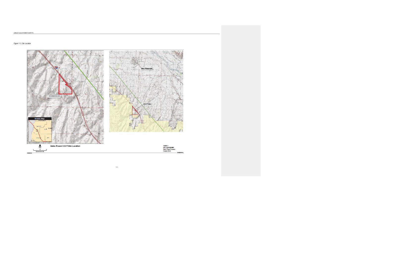
Langley Gulch power plant (LGPR) is located in Payette County, approximately 5 miles south of New Plymouth, Idaho; south of Exit 9 on Interstate 84. A map showing the physical location of LGPR is included as Figure 1-1. Payette County has been identified by the Idaho Department of Environmental Quality (IDEQ) as an attainment or unclassifiable area for all regulated criteria pollutants.
In accordance with IDAPA 58.01.01.314, this application submittal includes a project description, process flow diagram, emission rates and control equipment, State and Federal regulatory review, and compliance certifications. IDEQ permit application forms are provided in Appendix A.
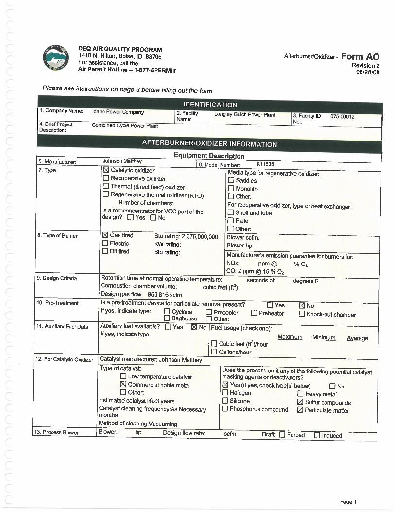
LGPR has a nominal capacity of approximately 269 megawatts (MW). The project includes a Siemens SGT6-5000F gas turbine in a one-on-one combined-cycle configuration with a Siemens SST-700 high pressure and SST900RH intermediate pressure steam turbine. The combustion turbine is equipped with a heat recovery steam generator (HRSG) which includes supplemental natural gas firing (duct firing). BACT is incorporated into the design of the facility. Dry low NOx burners and selective catalytic reduction (SCR) control NOx emissions. In addition, an oxidation catalyst controls CO and VOC emissions. Good combustion practices and burning pipeline quality natural gas minimize emissions of all remaining pollutants.
In addition to the combustion turbine, other associated emissions equipment for the facility include a diesel-fired emergency generator, a fire pump diesel engine, dry chemical storage silos, and a wet cooling tower. A facility overview drawing is included as Figure 1-2 and a scaled site plan identifying the equipment is provided as Figure 1-3.
Emission rates for each emission source are provided as well as a description of any control equipment.
A process flow diagram of the LGPR Combined Cycle Power Plant is presented in Figure 1-4.
LANGLEY GULCH POWER PLANT PTC
1-2
Figure 1-1: Site Location

LANGLEY GULCH POWER PLANT PTC
1-3
Figure 1-2: Facility Overview
Comment [kmk1]: The text on this map is really hard to read…but looks like DEQ accepted it in the PTC.

LANGLEY GULCH POWER PLANT PTC
1-4
Figure 1-3: Plant Layout

1-5
Figure 1-4: Langley Gulch Power Plant - Process Flow Diagram
Gas Turbine
Natural Gas AirEx
haus
t Hea
t
Generator Electricity
Water Steam Generator Electricity
Steam
Snake
Rive
r
Cooling Water
Water Return
Steam Condenser
Exhaust Stack
Cooling Tower
Steam TurbineExhaust Gas to Steam Heat Exchange
Cooling Water to Steam Heat Exchange
2-1
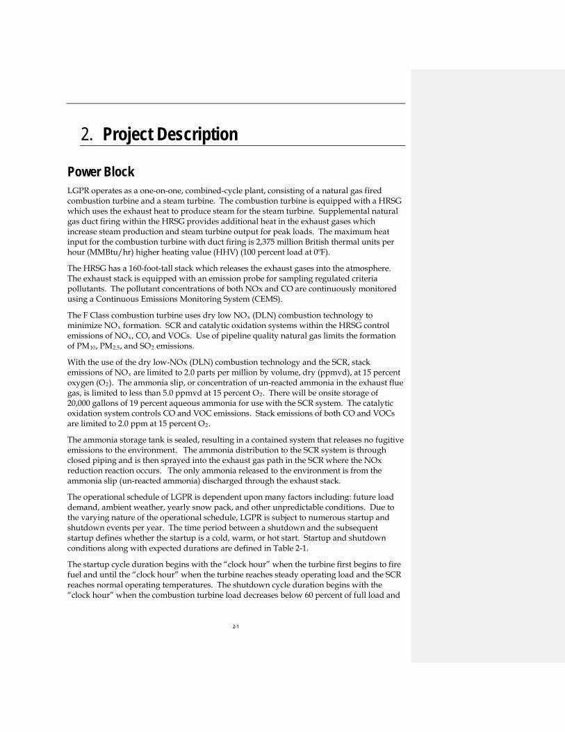
2. Project Description
Power Block LGPR operates as a one-on-one, combined-cycle plant, consisting of a natural gas fired combustion turbine and a steam turbine. The combustion turbine is equipped with a HRSG which uses the exhaust heat to produce steam for the steam turbine. Supplemental natural gas duct firing within the HRSG provides additional heat in the exhaust gases which increase steam production and steam turbine output for peak loads. The maximum heat input for the combustion turbine with duct firing is 2,375 million British thermal units per hour (MMBtu/hr) higher heating value (HHV) (100 percent load at 0ºF).
The HRSG has a 160-foot-tall stack which releases the exhaust gases into the atmosphere. The exhaust stack is equipped with an emission probe for sampling regulated criteria pollutants. The pollutant concentrations of both NOx and CO are continuously monitored using a Continuous Emissions Monitoring System (CEMS).
The F Class combustion turbine uses dry low NOx (DLN) combustion technology to minimize NOx formation. SCR and catalytic oxidation systems within the HRSG control emissions of NOx, CO, and VOCs. Use of pipeline quality natural gas limits the formation of PM10, PM2.5, and SO2 emissions.
With the use of the dry low-NOx (DLN) combustion technology and the SCR, stack emissions of NOx are limited to 2.0 parts per million by volume, dry (ppmvd), at 15 percent oxygen (O2). The ammonia slip, or concentration of un-reacted ammonia in the exhaust flue gas, is limited to less than 5.0 ppmvd at 15 percent O2. There will be onsite storage of 20,000 gallons of 19 percent aqueous ammonia for use with the SCR system. The catalytic oxidation system controls CO and VOC emissions. Stack emissions of both CO and VOCs are limited to 2.0 ppm at 15 percent O2.
The ammonia storage tank is sealed, resulting in a contained system that releases no fugitive emissions to the environment. The ammonia distribution to the SCR system is through closed piping and is then sprayed into the exhaust gas path in the SCR where the NOx reduction reaction occurs. The only ammonia released to the environment is from the ammonia slip (un-reacted ammonia) discharged through the exhaust stack.
The operational schedule of LGPR is dependent upon many factors including: future load demand, ambient weather, yearly snow pack, and other unpredictable conditions. Due to the varying nature of the operational schedule, LGPR is subject to numerous startup and shutdown events per year. The time period between a shutdown and the subsequent startup defines whether the startup is a cold, warm, or hot start. Startup and shutdown conditions along with expected durations are defined in Table 2-1.
The startup cycle duration begins with the “clock hour” when the turbine first begins to fire fuel and until the “clock hour” when the turbine reaches steady operating load and the SCR reaches normal operating temperatures. The shutdown cycle duration begins with the “clock hour” when the combustion turbine load decreases below 60 percent of full load and
2-2
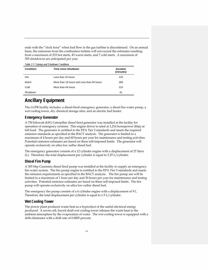
ends with the “clock hour” when fuel flow to the gas turbine is discontinued. On an annual basis, the emissions from the combustion turbine will not exceed the estimates resulting from a maximum of 253 hot starts, 45 warm starts, and 7 cold starts. A maximum of 305 shutdowns are anticipated per year.
Table 2-1: Startup and Shutdown Conditions Condition Time since Shutdown Duration
(minutes)
Hot Less than 16 hours 125
Warm More than 16 hours and Less than 64 hours 280
Cold More than 64 hours 310
Shutdown 41
Ancillary Equipment The LGPR facility includes: a diesel-fired emergency generator, a diesel fire water pump, a wet cooling tower, dry chemical storage silos, and an electric fuel heater.
Emergency Generator A 750 kilowatt (kW) Caterpillar diesel fired generator was installed at the facility for operation of emergency systems. This engine driver is rated at 1,214 horsepower (bhp) at full load. The generator is certified to the EPA Tier 2 standards and meets the required emission standards as specified in the BACT analysis. The generator is limited to a maximum of 4 hours per day and 60 hours per year for maintenance and testing activities. Potential emission estimates are based on these self-imposed limits. The generator will operate exclusively on ultra low sulfur diesel fuel.
The emergency generator consists of a 12 cylinder engine with a displacement of 27 liters (L). Therefore, the total displacement per cylinder is equal to 2.25 L/cylinder.
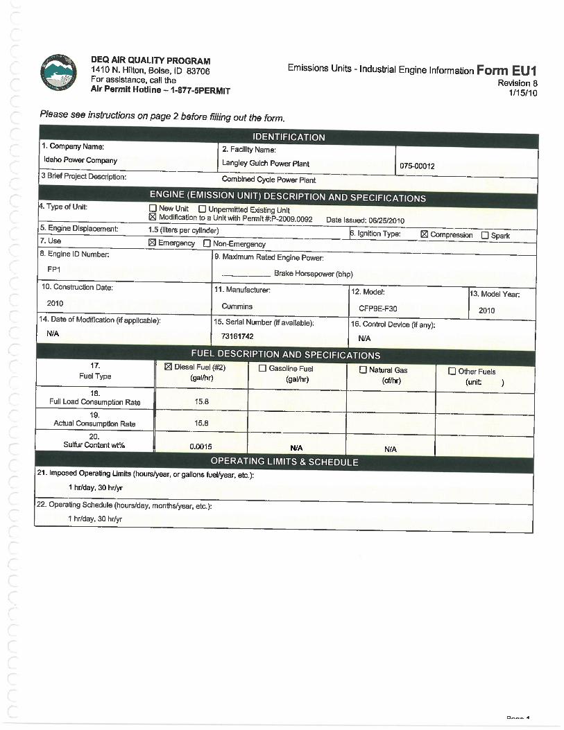
Diesel Fire Pump A 305 bhp Cummins diesel fired pump was installed at the facility to supply an emergency fire water system. The fire pump engine is certified to the EPA Tier 3 standards and meets the emission requirements as specified in the BACT analysis. The fire pump use will be limited to a maximum of 1 hour per day and 30 hours per year for maintenance and testing activities. Potential emission estimates are based on these self-imposed limits. The fire pump will operate exclusively on ultra low sulfur diesel fuel.
The emergency fire pump consists of a 6 cylinder engine with a displacement of 9 L. Therefore, the total displacement per cylinder is equal to 1.5 L/cylinder.
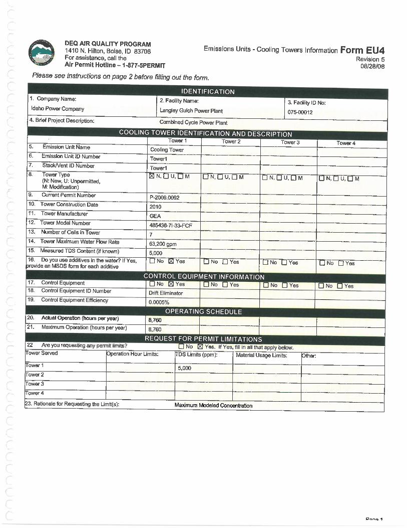
Wet Cooling Tower The power plant produces waste heat as a byproduct of the useful electrical energy produced. A seven cell, forced draft wet cooling tower releases the waste heat to the ambient atmosphere by the evaporation of water. The wet cooling tower is equipped with a drift eliminator with a drift rate of 0.0005 percent.

2-3
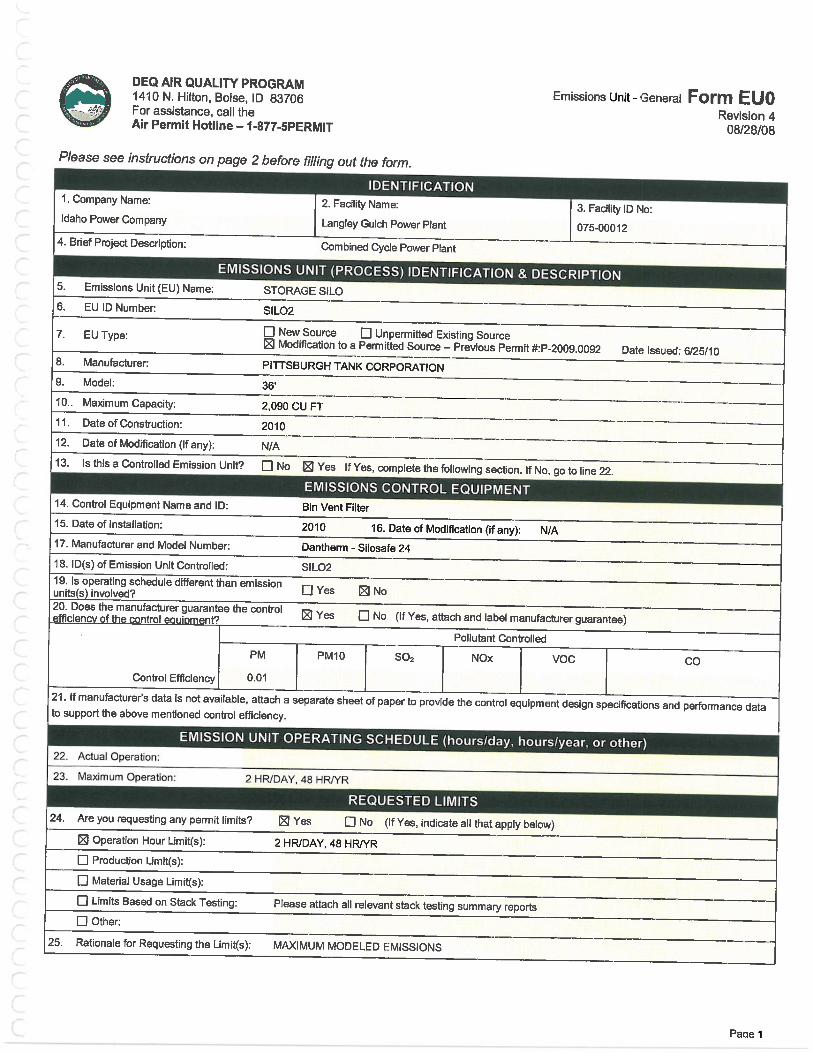
Dry Chemical Storage Silos The water treatment process requires the use of lime, magnesium oxide, and soda ash for removing suspended solids in the cooling water. These chemicals are stored onsite in bulk storage silos. During chemical loading operations, estimated to happen once per month, small amounts of PM emissions are expected to occur. The silo vents is equipped with filter media to limit the amount of PM emissions. Emissions from the loading events are included in the facility wide emission calculations

LANGLEY GULCH POWER PLANT
3-1
3. Emissions Unit Information This section provides an emissions summary for the LGPR Project.
Emissions rates for the LGPR project include: a Siemens SGT6-5000F combustion turbine operating in combined-cycle mode with supplemental duct firing, an emergency diesel fired generator, a diesel fire pump, a wet cooling tower, and dry storage silos. Additionally, fugitive road dust from on-site access roads to the facility is provided for informational purposes.
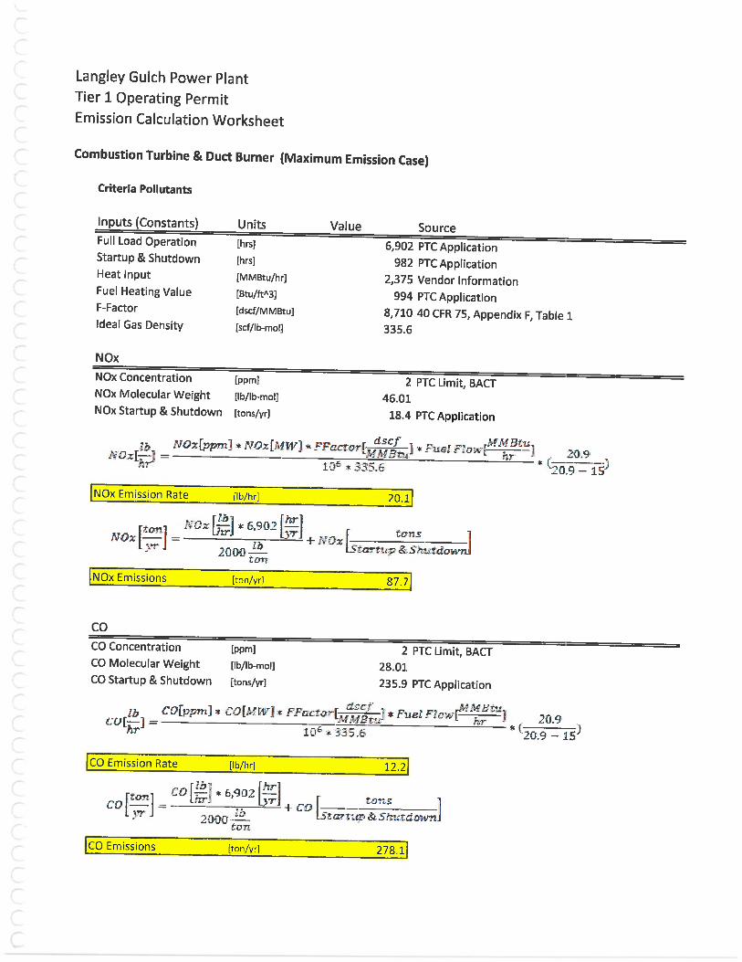
Natural Gas Combustion Turbine with Duct Burners Emissions The emission rates for the F Class combustion turbine are shown in Table 3-1. Emissions of NOx, CO, and VOCs are based on BACT emission rate of 2 ppmvd at 15 percent O2. Emissions for SO2 and PM10 are based on turbine design data and engineering estimates. Emissions in Table 3-1 are estimated at an ambient temperature of 0ºF, with the combustion turbine operating at base load with duct firing.
Table 3-1: Emissions for F-Class Combustion Turbines with Duct Burners Pollutant Hourly Emissions (lb/hr) Annual Emissions (tpy)
NOx Emissions 20.1 87.7
CO Emissions 12.2 278.1
SO2 Emissions 3.41 12.5
PM10 Emissions 12.55 48.5
VOC Emissions 7.0 74.9
CO2 Emissions 277,030 1,092,050
CH4 Emissions 5.2 20.6
N2O Emissions 0.5 2.1
Table 3-2 shows the annual LGPR toxic air pollutant (TAP) emissions from the F Class combustion turbine combined with natural gas duct firing. Emissions of TAPs were estimated using natural gas emissions factors from EPA’s AP-42, Fifth Edition, Table 3.1-3 and Tables 1.4-3 and 1.4-4 for the combustion turbine and duct firing, respectively. Annual emissions are estimated with 7,884 hours of operation per year. HAP emissions for the F Class combustion turbine and combined with duct firing were estimated at 10.4 tpy. Detailed emission calculations are provided in Appendix B.

LANGLEY GULCH POWER PLANT
3-2
Table 3-2: TAP Emission Summary for F-Class Combustion Turbine with Duct Firing Pollutant 24-Hr Ave. Emissions (lb/hr) Annual Ave. Emissions (lb/hr)
3-Methylchloranthrene 3.93E-07 Ammonia 1.86E+01 Benzene 2.35E-02 Benzo(a)pyrene 2.62E-07 Formaldehyde 1.38E+00 Hexane 4.36E-01 Naphthalene 2.92E-03 Pentane 6.30E-01 Toluene 2.78E-01 Flourene 6.11E-07 Xylenes 1.37E-01 Acetaldehyde 7.68E-02 Acrolein 1.37E-02 1,3-Butadiene 8.26E-04 Nitrous Oxide 6.94E+00 Sulfuric Acid 2.61E-01 PAH 7.34E-03 POM 2.36E-06 Arsenic 4.36E-05 Barium 1.07E-03 Beryllium 2.62E-06 Cadmium 2.40E-04 Chromium 3.39E-04 Cobalt 2.04E-05 Copper 2.06E-04 Manganese 9.21E-05 Mercury 6.30E-05 Molybdenum 2.67E-04 Nickel 4.58E-04 Selenium 5.82E-06 Vanadium 5.58E-04 Zinc 7.03E-03
Operating Profile The combustion turbine can operate at a wide range of electrical output levels while achieving the permitted BACT emission concentrations. The turbine utilizes automatic control logic to adjust fuel fractioning and cooling flows in order to reduce the emission levels at varying output levels. Depending on the ambient conditions, the output can be

LANGLEY GULCH POWER PLANT
3-3
turned down to approximately 50% of full load while meeting all permitted emission levels. Real-time CEMS data is used to verify that the turbine is within the permitted emission range. In addition, both the combustion turbine and the duct burners operate exclusively on pipeline quality natural gas which limits the SO2 and PM emissions by the maximum fuel throughput.
Emissions Control Systems and Monitoring The combustion turbine has dry low NOx burners as an integral part of the combustion system. The burners are in use any time the combustion turbine is operated and cannot be taken out of service. The burners fraction the fuel into the turbine to optimize the fuel-to-air ratio in order to get a lean burn and limit the production of thermal NOx. Downstream of the turbine exhaust, inside the HRSG, an oxidation catalyst and a selective catalytic reduction system are installed for further emissions reduction. The oxidation catalyst is a dry, precious metal catalyst. The catalyst oxidizes the flue gas as it passes through, reducing the emissions of both CO and VOCs. The catalyst is permanently installed and requires no support systems to be activated; however, the removal efficiency of the catalyst is reduced at low temperature. Therefore, during a startup event, the catalyst efficiency is reduced until flue gas temperatures rise and subsequently heat up the catalyst bed. Through historical observations, the catalyst efficiency begins to increase approximately 20-30 minutes after the combustion turbine starts. The selective catalytic reduction system is immediately downstream of the oxidation catalyst. The blower pulls hot flue gas from the HRSG through an ammonia conditioning skid. The liquid ammonia (19% aqueous) is sprayed into a mixing chamber with the hot flue gas where it vaporizes. The vaporized ammonia is then sent into a grid of injection nozzles upstream of the catalyst bed and mixes with the flue gas. As the flue gas and ammonia contact the catalyst bed, the NOx and NH3 react and produce nitrogen gas and water vapor as an outlet product. This system relies on the vaporization of the ammonia to work effectively, and therefore, cannot be operated until the temperature of the catalyst and flue gas elevated. During a startup event, the ammonia system is activated when the turbine output is approximately 50-60 percent of full load. Once activated, the ammonia system stays operational throughout the entire range of operations for the combustion turbine. At the stack exit, a CEMS umbilical pulls real-time samples of the flue gas and returns them to the emissions analyzers. The analyzers read the NOx, CO, and O2 values of the exiting flue gas into the atmosphere. The real-time and calculated hourly averages of the pollutants are sent to the onsite operator to ensure the emissions control systems are operating within the established ranges. The CEMS system is calibrated on a daily basis to ensure accuracy. In addition, the CEMS is subjected to a linearity check quarterly and an annual relative accuracy test audit in accordance with the quality assurance checks required under 40 CFR 75; Continuous Emissions Monitoring.
Equations The hourly emission rates for the combustion turbine are based upon the guarantee values provided by the turbine vendor and emission control equipment vendors. The annual emissions were based upon the maximum hourly emissions, maximum operating profile and sum of startup and shutdown emissions. The equations for estimating emissions are included in with the emission calculations.
LANGLEY GULCH POWER PLANT
3-4
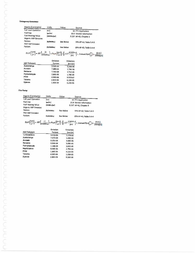
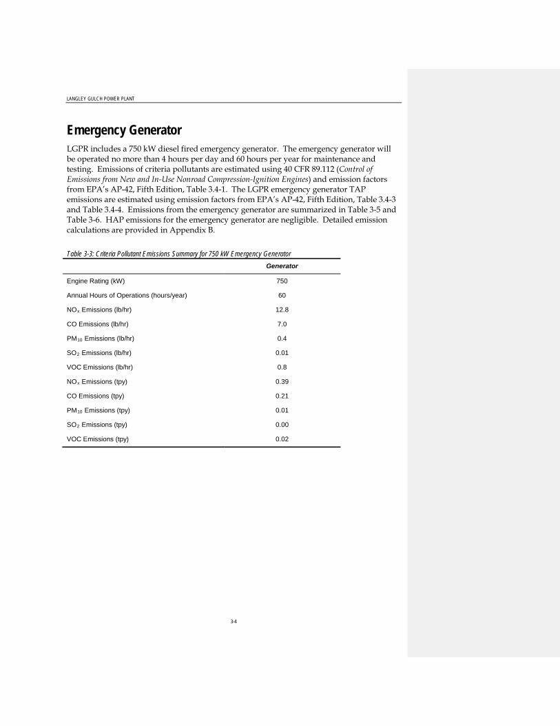
Emergency Generator LGPR includes a 750 kW diesel fired emergency generator. The emergency generator will be operated no more than 4 hours per day and 60 hours per year for maintenance and testing. Emissions of criteria pollutants are estimated using 40 CFR 89.112 (Control of Emissions from New and In-Use Nonroad Compression-Ignition Engines) and emission factors from EPA’s AP-42, Fifth Edition, Table 3.4-1. The LGPR emergency generator TAP emissions are estimated using emission factors from EPA’s AP-42, Fifth Edition, Table 3.4-3 and Table 3.4-4. Emissions from the emergency generator are summarized in Table 3-5 and Table 3-6. HAP emissions for the emergency generator are negligible. Detailed emission calculations are provided in Appendix B.
Table 3-3: Criteria Pollutant Emissions Summary for 750 kW Emergency Generator
Generator
Engine Rating (kW) 750
Annual Hours of Operations (hours/year) 60
NOx Emissions (lb/hr) 12.8
CO Emissions (lb/hr) 7.0
PM10 Emissions (lb/hr) 0.4
SO2 Emissions (lb/hr) 0.01
VOC Emissions (lb/hr) 0.8
NOx Emissions (tpy) 0.39
CO Emissions (tpy) 0.21
PM10 Emissions (tpy) 0.01
SO2 Emissions (tpy) 0.00
VOC Emissions (tpy) 0.02

LANGLEY GULCH POWER PLANT
3-5
Table 3-4: TAP Emissions Summary for 750 kW Emergency Generator Pollutant 24-Hour Average Emission
(lb/hr) Annual Average Emissions
(lb/hr)
Acenaphtene 2.35E-07
Acenaphthylene 4.64E-07
Acetaldehyde 1.27E-06
Acrolein 9.65E-06
Anthracene 6.19E-08
Benzene 3.90E-05
Benzo(a)pyrene 1.29E-08
Benz(g,h,l)perylene 2.80E-08
Fluorene 6.44E-07
Formaldehyde 3.97E-06
Naphthalene 1.59E-04
Phenanthrene 2.05E-06
Propylene Oxide 3.42E-03
POM (7-PAH Group) 1.95E-07
Pyrene 1.87E-07
Toluene 3.44E-04
Total PAH 1.07E-05
Xylenes 2.36E-04
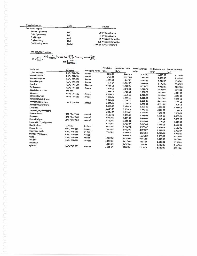
Fire Pump LGPR includes a 305 bhp diesel fired fire pump. The fire pump will be operated no more than 1 hour per day and 30 hours per year for testing and maintenance. Emissions of criteria pollutants are estimated using 40 CFR 60 Subpart IIII Emission Standards for stationary compression ignition internal combustion engines and emission factors from EPA’s AP-42, Fifth Edition, Table 3.3-1. The LGPR fire pump TAP emissions are estimated using emission factors from EPA’s AP-42, Fifth Edition, Table 3.3-2. Emissions from the fire pump are summarized in Table 3-7 and Table 3-8. HAP emissions for the fire pump are negligible. Detailed emission calculations are provided in Appendix B.

LANGLEY GULCH POWER PLANT
3-6
Table 3-5: Criteria Pollutant Emissions Summary for 305bhp Fire Pump Fire Pump
Engine Rating (bhp) 305
Annual Hours of Operations (hours/year) 30
NOx Emissions (lb/hr) 2.0
CO Emissions (lb/hr) 1.7
PM10 Emissions (lb/hr) 0.10
SO2 Emissions (lb/hr) 0.00
VOC Emissions (lb/hr) 0.10
NOx Emissions (tpy) 0.03
CO Emissions (tpy) 0.03
PM10 Emissions (tpy) 0.00
SO2 Emissions (tpy) 0.00
VOC Emissions (tpy) 0.00
Table 3-6: TAP Emissions Summary for 305 bhp Fire Pump Pollutant 24-Hour Average Emissions
(lb/hr) Annual Average Emissions
(lb/hr)
1,3-Butadiene 2.90E-07
Acenaphthene 1.00E-08
Acenaphthylene 3.56E-08
Acetaldehyde 5.40E-06
Acrolein 7.92E-06
Anthracene 1.32E-08
Benzene 6.57E-06
Benzo(a)pyrene 1.32E-09
Benz(g,h,l)perylene 3.44E-09
Fluoranthene 5.36E-08
Formaldehyde 8.31E-06
Naphthalene 7.26E-06
Phenanthrene 2.07E-07
Propylene Oxide 2.21E-04
POM (7-PAH Group) 1.23E-08
Pyrene 3.36E-08
Toluene 3.50E-05
Total PAH 1.18E-06
Xylenes 2.44E-05

LANGLEY GULCH POWER PLANT
3-7
Cooling Tower LGPR includes a forced draft, wet cooling tower equipped with drift eliminators with a drift rate of 0.0005 percent. The water flow rate is approximately 63,200 gpm with a maximum dissolved solids concentration of 5,000 parts per million by weight at nine cycles of concentration on the tower water. Particulate matter emissions are estimated using emission factors from EPA’s AP-42, Fifth Edition, Table 13.4-1 and from a technical paper presented at the 2001 Air and Waste Association Management, Calculating Realistic PM10 Emissions from Cooling Towers, J. Reisman and G. Frisbie. Emissions from the cooling tower are summarized in Table 3-9. Detailed emission calculations are provided in Appendix B.
Table 3-7: Criteria Pollutant Emissions Summary for Cooling Tower Pollutant Cooling Tower
PM10 Emissions (lb/hr) 0.66
PM10 Emissions (tpy) 2.91
Dry Chemical Storage Silos Three dry chemical storage silos are installed at the facility to house chemicals required in the water treatment process. The silos are enclosed from the environment with a vent installed near the peak of the silo to allow for equalization of pressure during chemical loading. The vents are equipped with bin vent filters which capture airborne particulate matter. The filters have a pulse air system to blast the captured PM off the filter and back into the silo. The silos are designed to hold a 30-day supply of chemicals to reduce loading time to approximately once per month. Loading the silo is expected to take approximately one hour per silo. For modeling purposes, the loading process was conservatively estimated to last 2 hours for each silo, with each silo being loaded twice per month.
Table 3-8: Criteria Pollutant Emissions Summary for Storage Silos Pollutant Storage Silos
PM10 Emissions (lb/hr) 0.13
PM10 Emissions (tpy) 0.01
Note: Emission numbers represent total for a maximum of six silos.
Fugitive Emissions The only source of fugitive dust emissions will be generated from on-site road traffic. The project site has a paved entrance road up to the administration building and around the site perimeter. The maintenance roads surrounding the facility are unpaved, gravel roads.

4-1
4. Applicable Requirements & Compliance
Facility Wide Requirements Fugitive Dust The facility must comply with the rules to control fugitive dust in accordance with IDAPA 58.01.01.650-651. [PTC Condition]
• The facility complies with the conditions by performing quarterly fugitive dust inspections. In addition, site improvements to minimize fugitive dust include paving of onsite roads and applying washed rock to the grounds.
Odors The facility must not discharge odorous gases, liquids, or solids in accordance with IDAPA 58.01.01.776. [PTC Condition]
• No odorous substances are emitted from the facility. In the event that odorous substances are discharged, the facility will take immediate actions to mitigate the source and will maintain records if complaints are received.
Visible Emissions The facility must comply with the rules to prevent visible emissions for each permitted emission source in accordance with IDAPA 58.01.01.625 [PTC Condition]
• The facility complies with the conditions by performing quarterly visible emission inspections for each permitted emission source. A “see” or “no see” evaluation is performed and any “see” evaluations are mitigated and an excess emissions report is submitted.
Process Weight Limitations The facility must comply with the PM emissions limit in accordance with IDAPA 58.01.01.700-703 for the storage silos and the cooling tower. [PTC Condition]
• The facility complies with the process weight limitations for the storage silos and the cooling tower by utilizing emission control devices and permit limitations.
o Storage silos are equipped with bin vent filters and are limited to 48 hours of loading time per year. A typical load of dry chemical is 48,000 lbs. In accordance with IDAPA 58.01.01.701.03, the emissions must not exceed 15.56 lb/hr. The silo emissions are calculated to be 0.13 lb/hr.
o Cooling tower is equipped with drift eliminators and has a TDS limit of 5,000 ppm. The maximum dissolved solids allowable in the cooling tower water are calculated to be 158,126 lbs. In accordance with IDAPA 58.01.01.701.03, the emissions must not exceed 23.26 lb/hr. The cooling tower emissions are calculated to be 0.66 lb/hr.

LANGLEY GULCH POWER PLANT
4-2
Fuel Burning Equipment The facility must comply with the PM emission limit in accordance with IDAPA 58.01.01.676 for the duct burners. [PTC Condition]
• The facility complies with the fuel burning equipment PM emission limit by operating the duct burners exclusively on pipeline quality natural gas. The PM emissions from the duct burners are guaranteed to be 2.4 lb/hr which is equal to 0.0007 gr/dscf @ 3% O2. The limit for PM grain loading is 0.015 gr/dscf @ 3% O2.
Fuel Sulfur Content The facility must comply with the sulfur content limitations in accordance with IDAPA 58.01.01.725. [PTC Condition]
• The facility only purchases diesel fuel that is rated for 15 ppm sulfur content. Fuel receipts are filed onsite.
Excess Emissions The facility must comply with the rules pertaining to excess emissions in accordance with IDAPA 58.01.01.130-136 for all permitted emission sources. [PTC Condition]
• The facility complies with the excess emissions rules through the use of a CEMS (combustion turbine and duct burner emissions), hourly runtime limits (combustion turbine, duct burner, fire pump, emergency generator, and storage silos), process weight restrictions (storage silos and cooling tower), visible emission observations, and fuel sulfur content (natural gas and diesel fuel).
• In the event of an excess emissions event, the DEQ is notified with 24 hours of the event and a detailed excess emissions report is filed within 15 days of the event.
Test Methods The facility shall use the approved test methods listed in the PTC or as determined acceptable by the DEQ to determine emissions compliance during any performance testing in accordance with IDAPA 58.01.01.157.02. [PTC Condition]
• The facility complies with the condition by submitting a testing protocol to the DEQ prior to the test date.
Combustion Turbine Emission Limits The combustion turbine must comply with the BACT and NSPS emission limits in accordance with PTC conditions 33-40. [PTC Condition]
• The combustion turbine is equipped with a CEMS to monitor and record real time NOx and CO emissions to verify compliance with conditions 33-35 and 37.
• The CEMS calculates the 12-month cumulative emissions of NOx and CO to verify compliance with condition 36.

LANGLEY GULCH POWER PLANT
4-3
• The combustion turbine and duct burner are operated exclusively on pipeline quality natural gas which contains less than 0.5 gr/hscf of sulfur. Natural gas has an heat content of approximately 994 btu/scf, therefore, the sulfur content of the pipeline natural gas is 0.0006 lb/MMbtu which is in compliance with condition 38.
• The emissions from the HRSG stack cannot exceed 12.55 lb/hr of PM. An initial emissions compliance performance test was performed. The PM emissions were verified to be less than the limit in condition 39.
• The ammonia slip from the HRSG stack shall not exceed 5 ppm @ 15% O2 on a 3-hour rolling average. An initial emissions compliance performance test was performed and verified compliance with condition 40.
Operating Requirements The combustion turbine must comply with the operational and design requirements in accordance with PTC conditions 41-50.
• The HRSG is equipped with an SCR to reduce the NOx emissions. Ammonia flow and a NOx CEMS provides monitoring capability to ensure the SCR is functioning properly.
• The HRSG is equipped with a catalytic oxidation system to reduce CO and VOC emissions. The CO CEMS provides monitoring capability to ensure the catalyst is functioning properly.
• Good combustion practices are integral into the design of the combustion turbine and duct burners. CEMS provides real time monitoring of the pollutants to verify good combustion as well as real time monitoring of the combustion system thermocouples.
• A NOx CEMS is installed and operated in accordance with the requirements of 40 CFR 75. The CEMS was certified to the requirements listed under 40 CFR 75.20.
• A CO CEMS is installed and operated in accordance with the requirements of 40 CFR 75. The CEMS was certified to the requirements listed under 40 CFR 75.20.
• The combustion turbine and pollution control equipment are maintained in accordance with the manufacturer’s recommendations. Real time monitoring of the turbine operation and pollutant concentrations provide verification that the equipment is functioning properly.
• The Combustion turbine operates exclusively on pipeline quality natural gas. The natural gas was tested for sulfur content during the certification testing.
• The ammonia injection flow meter is installed an operated in accordance with the manufacturer’s recommendations. The meter will be calibrated every 5 years.
• The ammonia injection flow rate is limited to 1.03 gpm on an hourly average. Real time monitoring and recording of the ammonia flow is on the CEMS.

LANGLEY GULCH POWER PLANT
4-4
• Operating hours for both the combustion turbine and the duct burners is monitored and recorded by the plant distributed control system (DCS).
Continuous Monitoring and Recordkeeping The combustion turbine and duct burner operations and emissions are monitored and recorded in accordance with the permit conditions 51-58.
• Each startup, shutdown, and low-load event is monitored and recorded by both the plant DCS and the CEMS.
• The NOx CEMS is installed and operated in accordance with 40 CFR 75. All modes of operation are monitored continuously and any excess emissions or monitor downtimes are recorded. Testing protocols and testing reports are submitted to the DEQ for any required performance testing. All records are maintained for 5 years.
• The NOx CEMS calculates and records the following: 1-hour NOx ppm, 1-hour NOx lb/hr, 3-hour NOx ppm, 12-month NOx tons, 1-hr applicable NOx limit, 3-hour applicable “blended average” limit, and any excess emissions produce an alarm.
• A NOx CEMS is installed.
• The NOx CEMS was certified in accordance with Performance Specification 2 of 40 CFR 60 Appendix B. The CEMS collects adequate data to validate each emissions hour and will automatically substitute data if the hour does not have validated data. The fuel flow meter is calibrated annually. No watt, steam, pressure or temperature devices feed into the CEMS logic, and therefore, no calibrations are required for accurate CEMS readings. The CEMS QA requirements are in accordance with 40 CFR 75 and the manufacturer’s recommendations.
• All data collected by the CEMS is reduced to hourly averages. Substitute data is used if the O2 concentration exceeds 19%. The validated data is used to identify excess emissions and semiannual reports are submitted that detail the CEMS downtime periods. The monthly emissions are verified to be within the limits listed under Table 1 of 40 CFR 60, Subpart KKKK.
• The CO CEMS is installed and operated in accordance with 40 CFR60, Subpart A. All modes of operation are monitored continuously and any excess emissions or monitor downtimes are recorded. Testing protocols and testing reports are submitted to the DEQ for any required performance testing. All records are maintained for 5 years.
• The CO CEMS calculates and records the following: 1-hour CO ppm, 1-hour CO lb/hr, 3-hour CO ppm, 12-month CO tons, 1-hr applicable CO limit, 3-hour applicable “blended average” limit, and any excess emissions produce an alarm.
Monitoring and Recordkeeping The facility maintains records to verify compliance with the fuel requirements, ammonia injection flow rate, and the hours of operation for the combustion turbine and duct burners.

LANGLEY GULCH POWER PLANT
4-5
• The natural gas fired in the combustion turbine is verified to meet the requirements of pipeline natural gas in accordance with 40 CFR 75, Appendix D, Section 2.3.1.4(a)(3). The testing frequency (annually) of the gas is in accordance with 40 CFR 75, Appendix D, Table D-5.
• The CEMS is used to record the ammonia injection flow rate and verified not to exceed the limit.
• The plant DCS monitors and records the operating hours of both the combustion turbine and the duct burners.
Performance Testing The facility shall comply with the performance testing requirements listed in permit conditions 64 – 68.
• The initial performance testing for the combustion turbine was completed on June 17, 2012. Compliance with each permit limit was verified.
• An fuel sulfur content analysis was performed during the performance testing to verify that the fuel met the definition of pipeline natural gas.
• A nine run RATA was performed to ensure the accuracy of the CEMS.
Reporting The facility complies with the reporting requirements defined in permit conditions 69-72.
• Excess emission and monitor downtime summary reports are submitted semiannually to the DEQ. Performance test reports are submitted annually.
• Excess emissions and downtime are verified against the 40 CFR 60, Subpart KKKK limits.
• Excess emissions of sulfur are determined to occur if the results of the lab analysis indicate that the sulfur content exceeds 0.5 gr/hscf in accordance with the pipeline natural gas definition in 40 CFR 72.2.
• Semiannual reports, including the CEMS downtime report and any excess emission reports are submitted each 6-month period.
Emergency Diesel Generator and Diesel Fire Pump Emission Limits The emergency diesel generator and the diesel fire pump are operated and maintained in order to comply with the permitted emission limits.
• An emergency diesel generator certified to the EPA Tier 2 standards was purchased, installed and operated to ensure compliance with the permitted emission levels.
• A diesel fire pump certified tot the EPA Tier 3 standards was purchased, installed, and operated to ensure compliance with the permitted emission levels.

LANGLEY GULCH POWER PLANT
4-6
Operating Requirements The facility shall comply with the operating requirements listed under permit conditions 77 – 82 to ensure compliance.
• The emergency generator is not operated in excess of 4 hours per day or 60 hours per year for maintenance and testing purposes. The diesel fire pump is not operated in excess of 1 hour per day or 30 hours per year for maintenance and testing purposes.
• The emergency generator and fire pump installed, maintained, and operated in accordance with the manufacturer’s instructions.
• The emergency generator and the fire pump are operated and maintained in accordance with the manufacturer’s recommendation. In addition, both engines are operated exclusively on ultra low sulfur diesel (ULSD).
• The emergency generator and the fire pump have non-resettable hour meters installed.
Monitoring and Recordkeeping The facility shall monitor and keep records to ensure compliance with permit conditions 83 – 86.
• An excel spreadsheet log is filled out for both the emergency generator and the fire pump each day that they are operated. The log calculates the monthly and 12-month operating time.
Cooling Tower Operating Requirements The facility shall comply with the operating requirements listed in permit conditions 87 – 90 to ensure compliance.
• The cooling tower was designed and constructed with drift eliminators to minimize the PM emissions.
• The drift eliminators are permanently installed in the cooling tower and cannot be taken out of service.
• The cooling tower is operated in accordance with the manufacturer’s instructions.
• The total dissolved solids (TDS) limit is maintained below the permitted levels by blowing down concentrated water and making up with clean water. The system flow rate is maintained within the limits by throttling the riser valves.
Monitoring and Recordkeeping The plant DCS system monitors and records the cooling tower operations continuously.
• Electronic records are available to verify both the conductivity and flow rate of the system.

LANGLEY GULCH POWER PLANT
4-7
Dry Chemical Storage Silos Operating Requirements The facility shall comply with the operating requirements listed under permit conditions 92-94.
• The dry chemical silos have bin vent filters installed, which capture the PM emissions during loading operations
• The bin vent filter is installed and operated in accordance with the manufacturer’s instructions any time material is loaded into the silo.
• An O&M manual has been developed which describes the methods used to ensure the integrity of the bin vent filter is maintained in accordance with the good operating practices.
Permit to Construct General Provisions General Compliance The facility must comply with all terms and conditions of the Permit to Construct and with the Rules for the Control of Air Pollution in Idaho.
• The conditions of the permit are verified to be in compliance. Monitoring and recordkeeping terms of the permit are maintained at the facility.
Inspection and Entry The facility shall comply with the requirement that DEQ employees may enter the facility and review the recordkeeping documents, inspect the facility, and/or sample the substances to ensure compliance.
Construction and Operation Notification The facility shall comply with the notification requirements under permit condition 99.
• A notification of the date of initiation of construction was submitted on 7/12/10.
o No delays or suspensions of construction occurred, and therefore, no notification was required.
• A notification of the anticipated date of initial startup was submitted on 3/19/12.
• A notification of the actual date of initial startup was submitted on 4/16/12.
• The facility has not reached the maximum production rate, and therefore, no notification has been submitted.
Performance Testing The facility will comply with the performance testing conditions under permit conditions 100-102.

LANGLEY GULCH POWER PLANT
4-8
• A testing protocol was submitted to the DEQ on 5/17/12 which detailed the intended testing and monitoring that was expected to take place.
• A notification of the upcoming testing was submitted to the DEQ on 5/22/12 to allow a representative to be onsite during the testing.
• A testing report was submitted following the testing, which summarized the results and verified compliance with the permitted emission levels.
Monitoring and Recordkeeping The records related to the conditions of the Permit to Construct, as well as records which support the control equipment, operating conditions and other air quality related functions are maintained for 5 years.
Certification All documents and reports submitted to the DEQ in relation to the Permit to Construct are certified to be true, accurate, and complete by the Responsible Official.
False Statements No knowingly false statements or certifications are made.
Tampering No monitoring devices or methods for compliance verification are tampered with or purposely made inaccurate.
Insignificant Activities The following activities are requested to be included under the Tier 1 operating permit.
• Operation, loading and unloading of volatile organic compound storage tanks, ten thousand (10,000) gallons capacity or less, with lids or other appropriate closure, vp not greater than eighty (80) mm Hg at twenty-one (21) degrees C. Operation, loading and unloading of gasoline storage tanks, ten thousand (10,000) gallons capacity or less, with lids or other appropriate closure.
• Welding using not more than one (1) ton per day of welding rod.
• Space heaters and hot water heaters using natural gas, propane or kerosene and generating less than five million (5,000,000) Btu/hr.

LANGLEY GULCH POWER PLANT
5-9
5. State and Federal Regulation Applicability A full state and federal regulatory applicability analysis was included in both the original PTC application and the DEQ issued Statement of Basis. The following federal applicability shows the rules that have been promulgated since the original application was submitted.
40 CFR 52 §52.21(b)(49) (49) Subject to regulation means, for any air pollutant, that the pollutant is subject to either a provision in the Clean Air Act, or a nationally-applicable regulation codified by the Administrator in subchapter C of this chapter, that requires actual control of the quantity of emissions of that pollutant, and that such a control requirement has taken effect and is operative to control, limit or restrict the quantity of emissions of that pollutant released from the regulated activity. Except that:
(i) Greenhouse gases (GHGs), the air pollutant defined in § 86.1818-12(a) of this chapter as the aggregate group of six greenhouse gases: Carbon dioxide, nitrous oxide, methane, hydrofluorocarbons, perfluorocarbons, and sulfur hexafluoride, shall not be subject to regulation except as provided in paragraphs (b)(49)(iv) through (v) of this section and shall not be subject to regulation if the stationary source maintains its total source-wide emissions below the GHG PAL level, meets the requirements in paragraphs (aa)(1) through (15) of this section, and complies with the PAL permit containing the GHG PAL.
(ii) For purposes of paragraphs (b)(49)(iii) through (v) of this section, the term tpy CO 2 equivalent emissions (CO 2 e) shall represent an amount of GHGs emitted, and shall be computed as follows:
(a) Multiplying the mass amount of emissions (tpy), for each of the six greenhouse gases in the pollutant GHGs, by the gas's associated global warming potential published at Table A-1 to subpart A of part 98 of this chapter—Global Warming Potentials. For purposes of this paragraph, prior to July 21, 2014, the mass of the greenhouse gas carbon dioxide shall not include carbon dioxide emissions resulting from the combustion or decomposition of non-fossilized and biodegradable organic material originating from plants, animals, or micro-organisms (including products, by-products, residues and waste from agriculture, forestry and related industries as well as the non-fossilized and biodegradable organic fractions of industrial and municipal wastes, including gases and liquids recovered from the decomposition of non-fossilized and biodegradable organic material).
( b ) Sum the resultant value from paragraph (b)(49)(ii)( a ) of this section for each gas to compute a tpy CO2 e.

6-1
6. References EPA. 1990. New Source Review Workshop Manual, Draft, Office of Air Quality Planning and Standards, Research Triangle Park, North Carolina, October, 1990.
EPA. 1995. SCREEN3, Model User’s Guide, EPA 454/B-95-004, September 1995.
EPA. 2004. User’s Guide for the AERMOD Meteorological Preprocessor, AERMET. Office of Air Quality Planning and Standards. November 2004.
EPA. 2004. User’s Guide for the AMS/EPA Regulatory Model, AERMOD. Office of Air Quality Planning and Standards. September 2004.
EPA. 2005. Appendix W of 40 CFR Part 51—Guideline On Air Quality Models (Revised), Office of Air Quality Planning and Standards, Research Triangle Park, North Carolina, November 2005.
EPA. 2009. AERMOD Implementation Guide. Office of Air Quality Planning and Standards. March 2009.
FLAG. 2008. Federal Land Managers’ Air Quality Related Values Workgroup (FLAG) Phase I Report. Revised 2008.
IDEQ. 2002. State of Idaho, Air Quality Modeling Guidelines (AQ-011). Idaho Department of Environmental Quality. December 2002.
IDEQ. 2010. Langley Gulch Power Plant, Permit-to-Construct. Idaho Department of Environmental Quality. June 2010