20
TIG 200 AC/DC PFC MV OWNER’S MANUAL www.duralloy.net.au | 1300 369 456
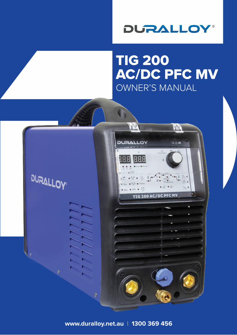
TIG 200 AC/DC PFC MVOWNER’S MANUAL
www.duralloy.net.au | 1300 369 456
Congratulations on your new DURALLOY® product!The DURALLOY range uses latest technology design and engineering to produce welding products that combine market leading value and features with durability. Designed for discerning operators who seek professional results and product quality without the price tag of a full professional setup. Design emphasis is placed on simple, functional design and operation. DURALLOY product is subject to stringent quality control and designed and manufactured to EN60974-1.2012 standards.
Common use of DURALLOY products include:• Light Engineering• Automotive• Home / Hobby Engineering• Farming• Industrial Maintenance & Repairs
For industrial welding solutions, check out the DURALLOY at www.duralloy.net.au
DURALLOY is a market leading provider of innovative power equipment solutions to a wide range of industries across Australia. Key product categories are; welding equipment, power generators and cleaning equipment.
www.duralloy.net.au | 1300 369 456
TIG 200 AC/DC PFC MVOWNER’S MANUAL
2
www.duralloy.net.au | 1300 369 456
TIG 200 AC/DC PFC MVOWNER’S MANUAL
CONTENTS
Know Your Machine
Quick Start Guide
Wireless Remote Control Configuration
Wiring Diagram
Care & Maintenance
Electrodes
Effects of MMA Welding Various Metals
Safety
Warranty
5
9
10
11
12
12
13
14
19
3
www.duralloy.net.au | 1300 369 456
TIG 200 AC/DC PFC MVOWNER’S MANUAL
TIG STICK
EN60974-1.2012
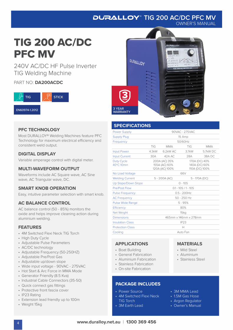
TIG 200 AC/DC PFC MV240V AC/DC HF Pulse Inverter TIG Welding MachinePART NO: DA200ACDC
3 YEAR WARRANTY
PFC TECHNOLOGYMost DURALLOY® Welding Machines feature PFC Technology for maximum electrical efficiency and consistent weld output.
DIGITAL DISPLAYVariable amperage control with digital meter.
MULTI-WAVEFORM OUTPUTWaveforms include AC Square wave, AC Sine wave, AC Triangular wave, DC.
SMART KNOB OPERATIONEasy, intuitive parameter selection with smart knob.
AC BALANCE CONTROLAC balance control (50 - 85%) monitors the oxide and helps improve cleaning action during aluminium welding.
FEATURES• 4M Switched Flexi Neck TIG Torch• High Duty Cycle • Adjustable Pulse Parameters• AC/DC technology• Adjustable Frequency (50-250HZ)• Adjustable Pre/Post Gas• Adjustable up/down slope • Wide input voltage - 90VAC - 275VAC• Hot Start & Arc Force in MMA Mode• Generator Friendly (8.5 Kva)• Industrial Cable Connectors (35-50)• Quick connect gas fittings• Protective front fascia cover• IP23 Rating• Extension lead friendly up to 100m• Weight 15kg
SPECIFICATIONSPower Supply 90VAC - 275VAC
Supply Plug 15 Amp
Frequency 50/60Hz
TIG MMA TIG MMA
Input Power 4.3kW 6.2kW AC 3.7kW 5.7kW DC
Input Current 30A 42A AC 28A 38A DCDuty Cycle 40oC 10min
200A (AC) 35%155A (AC) 60%120A (AC) 100%
170A (DC) 40%140A (DC) 60%110A (DC) 100%
No Load Voltage 66V
Welding Current 5 - 200A (AC) 5 - 170A (DC)
Up Slope/Down Slope 0 - 10S
Pre/Post Flow 0.1 - 10S / 1 - 10S
Pulse Frequency 0.5 - 200Hz
AC Frequency 50 - 250 Hz
Pulse Wide Range 5 - 95%
Efficiency 80%
Net Weight 15kg
Dimensions 465mm x 146mm x 278mm
Insulation Class IP23
Protection Class H
Cooling Auto Fan
APPLICATIONS• Boat Building• General Fabrication• Aluminium Fabrication• Stainless Fabrication• On-site Fabrication
MATERIALS• Mild Steel• Aluminium• Stainless Steel
PACKAGE INCLUDES• Power Source• 4M Switched Flexi Neck
TIG Torch• 3M Earth Lead
• 3M MMA Lead• 1.5M Gas Hose• Argon Regulator• Owner’s Manual
4

KNOW YOUR MACHINEMore detailed explanations of function on following pages.
1. Negative terminal (-) welding power output connection socket.
2. TIG torch gas connector.
3. Positive terminal (+) welding power output connection socket.
4. TIG torch remote connection socket
www.duralloy.net.au | 1300 369 456
TIG 200 AC/DC PFC MVOWNER’S MANUAL
5. LH Multifunction Display
6. RH Multifunction Display
7. Parameter Select/ Adjust Knob
8. MMA Hot Start Setting Indicator
9. MMA Welding Current Indicator
10. MMA Arc Force Setting Indicator
11. Pre Gas Flow Setting Indicator
12. Start Current Setting Indicator
13. Up Slope Setting Indicator
14. Tig Peak Welding Current Setting Indicator
15. Tig Base Welding Current Setting Indicator
16. Down Slope Setting Indicator
17. End Current Setting Indicator
18. Post Gas Flow Setting Indicator
19. Pulse Mode ‘Off’ Indicator
20. Pulse Mode ‘On’ Indicator
21. Pulse Frequency Setting Indicator
22. Pulse Width Setting Indicator
23. Clean Width Area/ AC Balance Adjustment
24. AC Frequency Adjustment
25. 4T Trigger Mode Indicator
26. Repeat Trigger Mode Indicator
27. 2T Trigger Mode Indicator
28. DC Wave Output Indicator
29. AC Triangle Wave Output Indicator
30. AC Sine Wave Output Indicator
31. AC Advanced Square Wave Output Indicator
32. Lift TIG Mode Indicator
33. HF TIG Mode Indicator
34. MMA Mode Indicator
CONTROL PANEL
5
1
4
2
3
34
33
32
3130
5 6
29
11
28 26 25 27
1213 14
19 20 23 24 21 22
1516 17
18
8
9
10
7
FURTHER CONTROLS EXPLAINEDLH Digital Multifunction Display (5)Before welding this displays the setting selected/being adjusted
using the control knob (7). During welding it displays welding
current. The parameter setting displayed is indicated by the
LEDs below the display; percentage (%), Current (A), Time (S) and
Frequency (Hz). If left inactive for several seconds, display will
revert back to main welding current setting.
RH Digital Multifunction Display (6)Before welding this displays secondary functions and error codes. During welding it displays welding voltage.
Multifunction Smart Control Knob (7)Move knob right/left and up/down to navigate around the control panel. Parameter/ setting selected will be indicated by the LED on the control panel and the value shown on the LH display (5). Adjust the parameter by turning the knob. Access the job/ program store/ recall function by pressing the knob.
Error IndicatorLights when over voltage, over current or electrical overheating (due to exceeding duty cycle) is detected and protection is activated. When protection is activated, welding output will be disabled until the safety system senses the overload has reduced sufficiently and indicator lamp goes out. May also trigger if machine experiences an internal power circuit failure.
MMA SETTINGSHot start (8)Hot start provides extra power when the weld starts to counteract the high resistance of the electrode and workpiece as the arc is started.
Arc Force (10)An MMA welding power source is designed to produce constant output current (CC). This means with different types of electrode and arc length; the welding voltage varies to keep the current constant. This can cause instability in some welding conditions as MMA welding electrodes will have a minimum voltage they can operate with and still have a stable arc. Arc Force control boosts the welding power if its senses the welding voltage is getting too low. The higher the arc force adjustment, the higher the minimum voltage that the power source will allow. This effect will also cause the welding current to increase. 0 is Arc Force off, 10 is maximum Arc Force. This is practically useful for electrode types that have a higher operating voltage requirement or joint types that require a short arc length such as out of position welds.
www.duralloy.net.au | 1300 369 456
TIG 200 AC/DC PFC MVOWNER’S MANUAL
TIG SETTINGSPre Flow (11)Pre-flow controls the period shielding gas will flow for when the torch is triggered before the arc starts. This purges the work area of atmospheric gas which could contaminate the weld before the weld starts.
Start Current Setting (12)Available in 4T trigger mode only, sets a welding current 5-100% of the main welding current activated when the trigger is held on to ‘latch’ the trigger before the main weld current is started. Once the trigger is released, the current will go through the upslope (13) period if it is set, to the main welding current (14).
Up Slope (13)When the trigger is activated, the welding current will increase gradually over the time selected up to the set main welding current (14).
Down Slope (16)When the trigger is released, the welding current will reduce gradually over the time selected down to 0. This allows the operator to complete the weld without leaving a ‘crater’ at the end of the weld pool.
End Current Setting (17)Available in 4T trigger mode only, sets a welding current 5-100% of the main welding current activated when the trigger is held on to ‘unlatch’ the trigger before the weld is finished. If downslope (16) is set, the current will go through the downslope period before going to the end current set. When the trigger is released, the arc will stop.
Post Flow Gas (18)Controls the period of time the shielding gas continues to flow for after the arc is stopped. This protects the weld area and torch tungsten from contamination while it is still hot enough to react with atmospheric gases, after the weld is finished.
PULSE SETTINGSOnly available when pulse mode (20) is selected.
Base Current (15)Sets the current of the low/ base pulse.
Pulse Frequency (21)Sets the rate that the welding output alternates between the peak and base current settings.
6
Pulse Width (22)Sets the time proportion as a percentage between the peak current and base current when using pulse mode. Neutral setting is 50%, the time period of the peak current and base current pulse is equal. Higher pulse duty setting will give greater heat input, while lower pulse duty will have the opposite effect.
AC SETTINGSOnly available in AC welding mode (29,30,31)
Clean Width Area/ ACBalance Adjustment (23)Adjusts the balance as a percentage between the forward and reverse current cycles when welding in AC output mode. The reverse part of the AC cycle gives the ‘cleaning’ effect on the weld material, while the forward cycle melts the weld material. Neutral setting is 0. Increased reverse cycle bias will give greater cleaning effect, less weld penetration and more heat in the torch tungsten, which gives the disadvantage of reducing the output current that can be used for a given tungsten size, to prevent the tungsten overheating. Increased forward cycle bias will give the opposite effect, less cleaning effect, greater weld penetration and less heat in the tungsten.
Ideally for maximum effectiveness, the clean width/AC balance should be set with as much forward cycle bias as possible, while still maintaining a sufficient level of oxidisation removal for a contamination free weld pool. The cleaner non-ferrous metal is before welding, the more effective it is to weld. This effect can also be used to reduce heat in the tungsten, allowing use of a pointed tungsten tip shape for a more defined arc.
AC Frequency Adjustment (24)Increasing AC frequency will focus the shape of the arc, resulting in a tighter, more controlled arc causing increased penetration and less heated affected area for the same current setting. Slower frequency will result in a wider, softer arc shape.
TIG 2T/4T TRIGGER CONTROL2T Mode (27)The trigger is pulled and held on to activate the welding circuit, when the trigger is released, the welding circuit stops.
4T (25)This is known as ’latching’ mode. The trigger is pulled once and released to activate the welding circuit, pulled and released again to stops the welding circuit. This function is useful to longer welds as the trigger is not required to be held on continuously. The Duralloy 200 AC/DC PFC MV also has more current control options that can be used in 4T mode.
www.duralloy.net.au | 1300 369 456
TIG 200 AC/DC PFC MVOWNER’S MANUAL
Repeat Mode (26)Cycles between peak (14) and base (15) welding current set, each time the trigger is activated. Also uses upslope (13) and down slope (17) when changing between the peak and base current settings. The number of cycles repeated before the arc stops is set on the LH display (5) when the repeat mode indicator (26) is lit.
AC/DC OUTPUT MODESDC (Direct Current) Welding Output (28)Suitable for TIG welding ferrous (iron based) metals such as mild steel and stainless steel, copper and titanium. TIG welding reactive metals such as Aluminium, Magnesium and Zinc requires AC (alternating current) output. When reactive metals are exposed to air they form an oxide layer that insulates the base metal and prevents welding current flowing, it also contaminates the weld pool. Reverse current flow is required to break through/ clean off this oxide layer so that welding can take place, while the current flow during the positive cycle does the majority of the heating of the weld pool area.
AC Triangle Wave Welding Output (29)Reduced heat input for same current setting. Especially useful for welding thin metal.
AC Sine Wave Welding Output (30)Traditional AC TIG welding wave form. Quieter, ‘soft’ arc characteristic.
AC Square Wave (31)Focused arc for maximum penetration, fast travel speed with best directional control.
7
TIG ARC STARTING MODESTIG HF/ Lift ignition modes (32/33)For TIG welding process, contact of the torch tungsten to the workpiece will cause contamination of the tungsten and the workpiece that will adversely affect the weld quality, especially when the tungsten is electrically energised. HF (high frequency) ignition sends a pulse of high energy electricity through the torch system that is capable of ‘jumping’ between the tungsten and the workpiece, ensuring arc starting without any contact between the tungsten and workpiece.
The disadvantage of HF ignition is that the high energy electrical pulse creates significant electrical and radio signal interference, which limits its use around sensitive electronic equipment such as computers.
Lift TIG ignition is a compromise that minimises tungsten contamination while eliminating the electrical interference of HF start systems.
Lift arc starting works by lightly resting the tungsten on the work piece, activating the torch trigger signal and then lifting the tungsten off. The control circuit will sense when the tungsten is removed from the work piece and send a low powered pulse of electricity through the tungsten that will cause the TIG arc to initiate. Because the tungsten is not ‘live’ when it is in contact with the work, contamination is minimised.
Program/Job MemoryThe DURALLOY TIG 200 AC/DC PFC MV has 10 memory/ job spaces that parameters can be saved to for easy recall. To access a saved program, press the control knob (7) and the program number 0-9 will show on the display. Adjust to the program number required by rotating the control knob. Once the program is accessed, it will automatically load. To return to normal parameter settings, move the control knob up, down, right or left. To save parameters set as a program, press and hold the control knob for a few seconds and the display will blink. The settings are now saved in the last program space that was selected. If setting parameters to save as a program, ensure that you start with a program number that the data is OK to overwrite, as the previous settings saved to that memory space will be lost.
www.duralloy.net.au | 1300 369 456
TIG 200 AC/DC PFC MVOWNER’S MANUAL
TIPS AND TRICKSPulse WeldingPulse welding mode switches the welding output between a high and low current output in a cyclical manner. When used correctly this function has substantial benefits in the TIG welding process including greater weld penetration for less work heat input and greater control of the weld pool.
The basic theory for setting the base current using pulse mode is that the base current should be sufficient to maintain the existing molten weld pool, while the peak current is sufficient to melt new metal in order to move/ expand the molten weld pool. Increased pulse frequency will have the effect of making the arc more tightly focused which is useful for fine stainless work and similar.
Pulsing can also be used to help move the weld pool, this technique is useful for welding out of position or with materials that have higher viscosity weld pool. Higher pulse duty setting will give greater heat input, while lower pulse duty will have the opposite effect.
Remote Current ControlThe DURALLOY 200AC/DC PFC MV can accept remote current control from a potentiometer/ analogue signal or a digital up/down button signal. Potentiometer remote control will change the current from the 5A minimum to the maximum set using the machine current control (30). Using an up/ down button remote signal, the current may be increased or decreased in 1A increments, or ‘scrolls’ up to 30A at a time if the button is held down. This is very useful for precision work. The DURALLOY 200AC/DC PFC MV can also be used with the DURALLOY Wireless remote control system. Refer to the accessories section in this manual for the options available.
Duty Cycle RatingWelding duty cycle is the percentage of actual welding time that can occur in a ten minute cycle. E.g. 20% at 160 amps - this means the welder can weld at 160 amps for 2 minutes and then the unit will need to be rested for 8 minutes. All duty cycle ratings are based on an ambient air temperature of 40°C with 50% humidity, which is the international standard for such a rating. In an environment with temperatures exceeding 40°C, the duty cycle will be less than stated. In ambient temperature less than 40°C, duty cycle performance will be higher.
8

Electrical ConnectionDURALLOY multi-voltage technology allows the machine to operate on a very wide range input voltages down as low as 90V. This means that limited capacity power supplies and long extension leads may be used without damaging the welder. However, as the supply voltage decreases, the maximum output current and duty cycle will also decrease.
To utilise the full output capacity of the machine using an extension cord, it should be a heavy duty version with a minimum cable core size of 2.5mm2. It is recommended to use the DURALLOY industrial duty 15A extension lead.
Operating EnvironmentAdequate ventilation is required to provide proper cooling. Ensure that the machine is placed on a stable level surface where clean cool air can easily flow through the unit. The DURALLOY 200AC/DC PFC MV has electrical components and control circuit boards which may be damaged by excessive dust and dirt, so a clean operating environment is important for reliable product life.
BASIC OPERATION1. ARC/ MMA Welding Operation1.1 Connect the earth cable quick connector to the negative
welding power output socket (1) Connect the earth clamp to the work piece. Contact with the work piece must be firm contact with clean, bare metal, with no corrosion, paint or scale at the contact point.
1.2 Insert an electrode into the electrode holder and connect the electrode holder and work lead to the positive welding power output socket (3).
Note: This polarity connection configuration is valid for most GP (General Purpose)
MMA electrodes. There are variances to this. If in doubt, check the electrode
specifications or consult the electrode manufacturer. Quick Start Guide - Welder
Installation
1.3 Connect the machine to suitable mains power using the mains input power lead. Switch the mains power switch to ‘on’ to power up the machine. Set to MMA welding mode (34)
1.4 Set welding parameters as required following instructions in the previous section. You are now ready to weld!
www.duralloy.net.au | 1300 369 456
TIG 200 AC/DC PFC MVOWNER’S MANUAL
2. TIG OperationNote: TIG operation requires an argon gas supply.
2.1 Connect earth cable quick connector to positive welding power output socket (3). Connect earth clamp to the work piece. Contact withwork piece must be a firm contact with clean, bare metal, with no corrosion, paint or scale at contact point.
2.2 Insert TIG torch power connection into the negative welding power output socket (1). Connect TIG torch remote plug to remote socket (4) and torch gas connection to the TIG gas outlet (2).
2.3 Connect the machine to suitable mains power using the mains input power lead. Switch the mains power switch to ‘on’ to power up the machine. Set the welding mode to ‘Lift TIG’ (32) or ‘HF TIG’ (33).
2.4 Assemble female gas quick connector to the gas line and regulator outlet fitting. Connect gas regulator to a gas cylinder (not included with machine) and connect female quick connector to male gas inlet on rear of machine. Ensure all connections are tight. Open gas cylinder valve and adjust regulator, flow should be between 5-10 l/min depending on application. Re-check regulator flow pressure with the torch triggered as static gas flow setting may drop once gas is flowing.
2.5 Set welding parameters as required followng the instructions in the previous section. You are now ready to weld!
QUICK START GUIDE - WELDER INSTALLATION
9
Any DURALLOY 200AC/DC PFC MV model can be configured to communicate exclusively with suitable DURALLOY wireless foot pedal or remote control panel. This is done by a simple process of synchronising the wireless remote control and the machine frequencies. Each interface frequency assigned is unique, so it is possible to use several wireless control systems/machines in the same area with no problems. The direct range of the DURALLOY wireless control system is approximately 100m, this will be affected by the physical location of the machine and the remote control.
To synchronise a remote control to a machine, follow these instructions:1.1 Ensure the remote control or foot pedal is switched on
1.2 Press and hold the main control adjustment knob in ‘select’ mode and turn the machine on.
1.3 As the machine powers up, the LCD display will light and then go blank again. When the display goes blank, release the control knob.
1.4 Within 10 seconds of releasing the knob, activate the remote control or foot pedal. The LCD display on the machine should blink twice to indicate successful synchronisation. Switch the machine off and back on again to start welding operation. If the operation is unsuccessful, repeat steps 1 to 5.
Please ensure the wireless foot pedal or remote control is switched off when not in use to conserve battery life. If the battery is left to go flat, the remote device may be required to be resynchronised with the machine again.
To remove the connection with a wireless remote control:2.1 Press and hold the main control adjustment knob down in
‘select’ mode and turn the machine on.
2.2 Continue holding the knob down after the LCD display goes blank. Eventually the display will blink with a wireless reset message.
2.3 Switch the machine off and back on again to start welding operation. The wireless synchronisation has now been removed.
www.duralloy.net.au | 1300 369 456
TIG 200 AC/DC PFC MVOWNER’S MANUAL
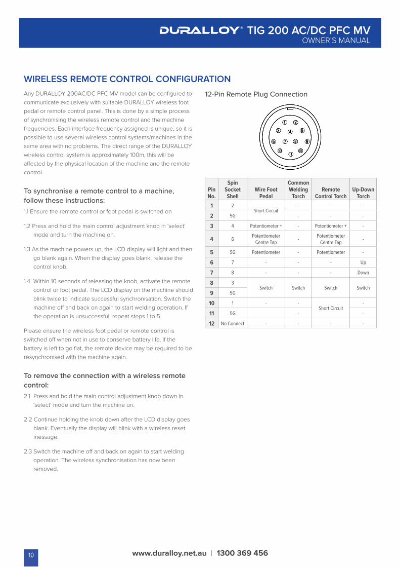
WIRELESS REMOTE CONTROL CONFIGURATION12-Pin Remote Plug Connection
Pin No.
Spin Socket Shell
Wire Foot Pedal
Common Welding
TorchRemote
Control TorchUp-Down
Torch1 2
Short Circuit- - -
2 5G - - -
3 4 Potentiometer + - Potentiometer + -
4 6 Potentiometer Centre Tap - Potentiometer
Centre Tap -
5 5G Potentiometer - Potentiometer -
6 7 - - - Up
7 8 - - - Down
8 3Switch Switch Switch Switch
9 5G
10 1 - -Short Circuit
-
11 5G - -
12 No Connect - - - -
10
www.duralloy.net.au | 1300 369 456
TIG 200 AC/DC PFC MVOWNER’S MANUAL
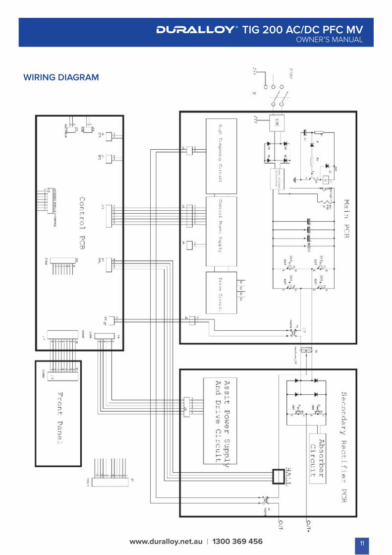
WIRING DIAGRAM
11
Keep your welding machine in top conditionThe DURALLOY 200AC/DC PFC MV does not require any special maintenance, however the user should take care of the machine as follows:
• Regularly clean the ventilation slots.
• Keep the casing clean.
• Check all cables before use.
• Check electrode holders, work lead/clamps and welding torches before use.
• Replace worn electrode holders and earth clamps, which do not provide a good connection.
• Replace worn consumable parts in a timely manner.
• Use a soft cloth or brush to clean electrical components.
• Do not use liquid cleaning products, water or especially solvents.
• Do not use compressed air to clean electrical components as this can force dirt and dust further into components, causing electrical short circuits.
• Check for damaged parts. Do not use the welderwith damaged parts.
• A damaged welder must be carefully checked by a qualified person to determine that it will operate properly. Check for breakage of parts, mountings and other conditions that may affect its operation. An authorised service centre should properly repair a damaged part. Have your welder repaired by an expert.
This appliance is manufactured in accordance with relevant safety standards. Only experts must carry out repairing of electrical appliances, otherwise considerable danger for the user may result. Use only genuine replacement parts. Do not use modified or non-genuine parts.
Storing the WelderWhen not in use the welder should be stored in the dry and frost-free environment.
WARNING! Before performing cleaning/maintenance, replacing cables / connections , make sure the welding machine is switched off and disconnected from the power supply.
www.duralloy.net.au | 1300 369 456
TIG 200 AC/DC PFC MVOWNER’S MANUAL
CARE & MAINTENANCESize of ElectrodesThe electrode size is determined by the thickness of metals being joined and can also be governed by the type of welding machine available. Small welding machines will only provide current (amperage) to run smaller sized electrodes.
For thin sections, it is necessary to use smaller electrodes otherwise the arc may burn holes through the job. A little practice will soon establish the most suitable electrode for a given application.
Storage of ElectrodesAlways store electrodes in a dry place and in their original containers.
Electrode PolarityElectrodes are generally connected to the electrode holder with the electrode holder connected positive polarity.
The work lead is connected to the negative polarity and is connected to the work piece. If in doubt consult the electrode data sheet.
ELECTRODES
12
High Tensile and Alloy SteelsThe two most prominent effects of welding these steels are the formation of a hardened zone in the weld area, and, if suitable precautions are not taken, the occurrence in this zone of under-bead cracks. Hardened zone and underbead cracks in the weld area may be reduced by using the correct electrodes, preheating, using higher current settings, using larger electrodes sizes, short runs for larger electrode deposits or tempering in a furnace.
Manganese SteelsThe effect on manganese steel of slow cooling from high temperatures causes embrittlement. For this reason it is absolutely essential to keep manganese steel cool during welding by quenching after each weld or skip welding to distribute the heat.
Cast IronMost types of cast iron, except white iron, are weldable. White iron, because of its extreme brittleness, generally cracks when attempts are made to weld it. Trouble may also be experienced when welding white-heart malleable, due to the porosity caused by gas held in this type of iron.
Copper and AlloysThe most important factor is the high rate of heat conductivity of copper, making pre-heating of heavy sections necessary to give proper fusion of weld and base metal.
Types of ElectrodesARC Welding electrodes are classified into a number of groups depending on their applications. There are a great number of electrodes used for specialised industrial purposes which are not of particular interest for everyday general work. These include some low hydrogen types for high tensile steel, cellulose types for welding large diameter pipes, etc. The range of electrodes dealt with in this publication will cover the vast majority of applications likely to be encountered; are all easy to use.
www.duralloy.net.au | 1300 369 456
TIG 200 AC/DC PFC MVOWNER’S MANUAL
EFFECTS OF MMA WELDING VARIOUS MATERIALS
13
Store and Retain this ManualRetain this manual for the safety warnings and precautions, assembly, operating, inspection, maintenance and cleaning procedures. Write the product serial number at the rear of this manual and keep this manual and the receipt in a safe and dry place for future reference.
Important Safety InformationFailure to follow the warnings and instructions may result in electric shock, fire, serious injury and/or death. Save all warnings and instructions for future reference.
www.duralloy.net.au | 1300 369 456
TIG 200 AC/DC PFC MVOWNER’S MANUAL
SAFETY
This is the safety alert symbol to alert you to potential personal injury hazards. Obey all safety messages that follow this symbol to avoid possible injury or death.
DANGER!Indicates a hazardous situation which, if not avoided, will result in death or serious injury.
WARNING!Indicates a hazardous situation which, if not avoided, could result in death or serious injury.
CAUTIONUsed with the safety alert symbol, indicates a hazardous situation which, if not avoided, could result in minor or moderate injury.
NOTE: used to address practices not related to personal injury.
General Safety Warnings1. Maintain labels and nameplates on the welder. These carry
important information. If unreadable or missing, contact DURALLOY for a replacement.
2. Avoid unintentional starting. Make sure the welder is setup correctly and you are prepared to begin work before turning on the welder.
3. Unplug before performing maintenance. Always unplug the welder from its electrical outlet before performing any inspection, maintenance, or cleaning procedures.
4. Never leave the welder unattended while energised. Turn power off before leaving the welder unattended.
5. Do not touch live electrical parts. Wear dry, insulating gloves. Do not touch the electrode or the conductor tong with bare hands. Do not wear wet or damaged gloves.
6. Protect yourself from electric shock. Do not use the welder outdoors. Insulate yourself from the work piece and the ground. Use non-flammable, dry insulating material if possible, or use dry rubber mats, dry wood or plywood, or other dry insulating material large enough to cover the area of contact with the work or the ground.
7. Avoid inhaling dust. Some dust created by power sanding, sawing, grinding, drilling, cutting, welding and other construction activities, contain chemicals known to cause cancer, birth defects or other harm. Your risk from these exposures varies, depending on how often you do this type of work. To reduce your exposure to these chemicals, work in a well-ventilated area, and work with approved safety equipment, such as dust masks that are specially designed to filter out microscopic particles.
8. People with pacemakers should consult their physician(s) before using this machine.
WARNING!Electromagnetic fields in close proximity to a heart pacemaker could cause interference, or failure of the pacemaker. The use of a Welder is NOT RECOMMENDED for pacemaker wearers. Consult your doctor.
9. Ensure that the unit is placed on a stable location before use.
WARNING!If this unit falls while plugged in, severe injury, electric shock, or fire may result.
10. Transportation Methods Lift unit with the handles provided, or use a handcart or similar device of adequate capacity. If using a fork lift vehicle, secure the unit to a skid before transporting.
CAUTIONDisconnect input power conductors from deenergized supply line before moving the welding power source.
11. Exercise good work practices.The warnings, precautions, and instructions discussed in this instruction manual cannot cover all possible conditions and situations that may occur. It must be understood by the operator that common sense and caution are factors which cannot be built into this product, but must be considered by the operator.
14
Welding Safety Instructions & Warnings
WARNING!Protect yourself and others from possible serious injury or death. Keep children away. Read the operating/Instruction manual before installing, operating or servicing this equipment. Have all installation, operation, maintenance,
and repair work performed by qualified people.
If an operator does not strictly observe all safety rules and take precautionary actions, welding products and welding processes can cause serious injury or death, or damage to other equipment or property.
Safe practices have developed from past experience in the use of welding and cutting. These practices must be learned through study and training before using this equipment. Some of these practices apply to equipment connected to power lines; other practices apply to engine driven equipment. Anyone not having extensive training in welding and cutting practices should not attempt to weld.
Safe practices are outlined in the European Standard EN60974-1 entitled: Safety in welding and allied processes.
WARNING!Only use safety equipment that has been approved by an appropriate standards agency. Unapproved safety equipment may not provide adequate protection. Eye and breathing protection must be AS/NZS compliant for the specific hazards in the work area.
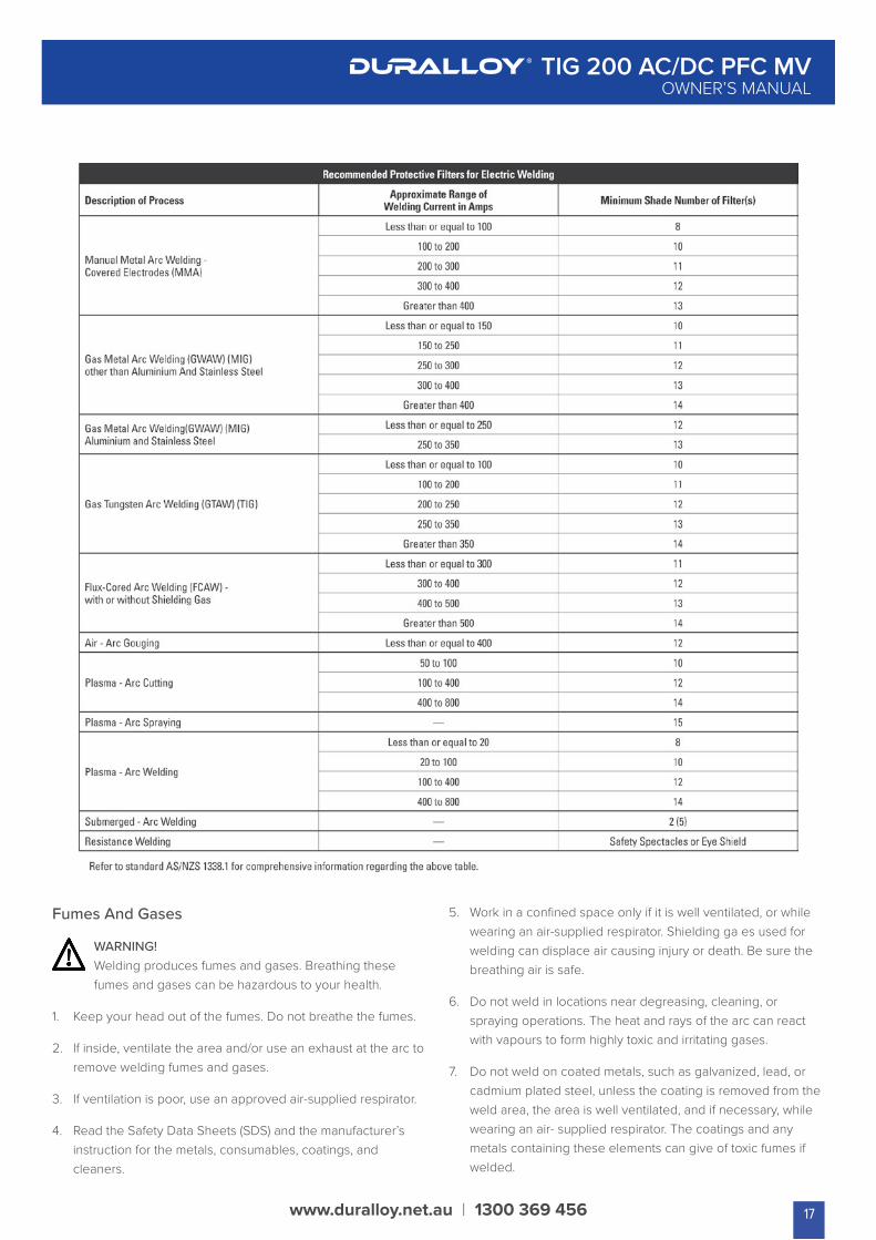
DANGER!Always wear AS/NZS compliant safety glasses and full face shield fitted with appropriate filter shade number. (Refer Filter Table in this safety section)
CAUTIONHeavy-duty work gloves, non-skid safety shoes and hearing protection used for appropriate conditions will reduce personal injuries.
CAUTIONHave the equipment serviced by a qualified repair person using identical replacement parts. This will ensure that the safety of the power tool is maintained.
www.duralloy.net.au | 1300 369 456
TIG 200 AC/DC PFC MVOWNER’S MANUAL
Personal Safety
CAUTIONKeep the work area well lit. Make sure there is adequate space surrounding the work area. Always keep the work area free of obstructions, grease, oil, trash, and other debris. Do not use equipment in areas near flammable chemicals, dust, and vapours. Do not use this product in a damp or wet location.
1. Stay alert, watch what you are doing and use common sense when operating equipment. Do not use a tool while you are tired or under the influence of drugs, alcohol or medication. A moment of distraction when operating equipment may result in serious personal injury.
2. Do not overreach. Keep proper footing and balance at all times. This enables better control of the power tool in unexpected situations.
Arc Rays can Burn Eyes and Skin
DANGER!Arc rays from the welding process produce intense heat and strong ultraviolet rays that can burn eyes and skin.
1. Use a Welding Helmet or Welding Face Shield fitted with a proper shade filter (refer AS 60974-1, AS/NZS 1337.1 and AS/NZS 1338.1 Safety Standards) to protect your face and eyes when welding or watching. (See Filter Table later in this section)
2. Wear approved safety glasses. Side shields are recommended.
3. Use protective screens or barriers to protect others from flash and glare; warn others not to watch the arc.
4. Wear protective clothing made from durable, flame-resistant material (wool and leather) and foot safety protection.
5. Never wear contact lenses while welding.
Noise Can Damage Hearing
CAUTIONNoise from some processes can damage hearing. Use AS/NZS compliant ear plugs or ear muffs if the noise level is high.
15
Work Environment Safety
CAUTIONUsed with the safety alert symbol, indicates a hazardous situation which, if not avoided, could result in minor or moderate injury.
1. When possible, move the work to a location well away from combustible materials. If relocation is not possible, protect the combustibles with a cover made of fire resistant material.
2. Remove or make safe all combustible materials for a radius of 10 metres around the work area. Use a fire resistant material to cover or block all doorways, windows, cracks, and other openings.
3. Enclose the work area with portable fire resistant screens. Protect combustible walls, ceilings, floors, etc., from sparks and heat with fire resistant covers.
4. If working on a metal wall, ceiling, etc., prevent ignition of combustibles on the other side by moving the combustibles to a safe location. If relocation of combustibles is not possible, designate someone to serve as a fire watch, equipped with a fire extinguisher, during the welding process and well after the welding is completed.
5. Do not weld or cut on materials having a combustible coating or combustible internal structure, as in walls or ceilings, without an approved method for eliminating the hazard.
6. After welding, make a thorough examination for evidence of fire. Be aware that visible smoke or flame may not be present for some time after the fire has started. Do not weld or cut in atmospheres containing dangerously reactive or flammable gases, vapours, liquids, and dust. Provide adequate ventilation in work areas to prevent accumulation of flammable gases, vapours, and dust.
7. Do not apply heat to a container that has held an unknown substance or a combustible material whose contents, when heated, can produce flammable or explosive vapours. Clean and purge containers before applying heat. Vent closed containers, including castings, before preheating, welding, or cutting.
www.duralloy.net.au | 1300 369 456
TIG 200 AC/DC PFC MVOWNER’S MANUAL
Electricity Can Kill
DANGER!Touching live electrical parts can cause fatal shocks or severe burns. The electrode and work circuit is electrically live whenever the output is on.
The input power circuit and machine internal circuits are also live when power is on. In semi-automatic or automatic wire welding, the wire, wire reel, drive roll housing, and all metal parts touching the welding wire are electrically live. Incorrectly installed or improperly grounded equipment is a hazard.
1. Do not touch live electrical parts.
2. Wear dry, hole-free insulating gloves and body protection.
3. Insulate yourself from the work and the ground using dry insulating mats or covers.
4. Disconnect input power before installing or servicing this equipment. Lock input power, disconnect switch open, or remove line fuses so power cannot be turned on accidentally.
5. Properly install and ground this equipment according to national, state, and local codes.
6. Turn off all equipment when not in use. Disconnect power to equipment if it will be left unattended or out of service.
7. Use fully insulated electrode holders. Never dip the holder in water to cool it or lay it down on the ground or the work surface. Do not touch holders connected to two welding machines at the same time or touch other people with the holder or electrode.
8. Do not use worn, damaged, undersized, or poorly spliced cables.
9. Do not wrap cables around your body.
10. Connect work piece to a good electrical ground.
11. Do not touch the electrode while in contact with the work (ground) circuit.
12. Use only well-maintained equipment. Repair or replace damaged parts as soon as practical.
13. In confined spaces or damp locations, do not use a welder with AC output unless equipped with a voltage reducer.
Arc rays from the welding process produce intense heat and strong ultraviolet rays that can burn eyes and skin. Use the following table to select the appropriate shade number for a Welding Helmet or Welding Face Shield.
16
www.duralloy.net.au | 1300 369 456
TIG 200 AC/DC PFC MVOWNER’S MANUAL
Fumes And Gases
WARNING!Welding produces fumes and gases. Breathing these fumes and gases can be hazardous to your health.
1. Keep your head out of the fumes. Do not breathe the fumes.
2. If inside, ventilate the area and/or use an exhaust at the arc to remove welding fumes and gases.
3. If ventilation is poor, use an approved air-supplied respirator.
4. Read the Safety Data Sheets (SDS) and the manufacturer’s instruction for the metals, consumables, coatings, and cleaners.
5. Work in a confined space only if it is well ventilated, or while wearing an air-supplied respirator. Shielding ga es used for welding can displace air causing injury or death. Be sure the breathing air is safe.
6. Do not weld in locations near degreasing, cleaning, or spraying operations. The heat and rays of the arc can react with vapours to form highly toxic and irritating gases.
7. Do not weld on coated metals, such as galvanized, lead, or cadmium plated steel, unless the coating is removed from the weld area, the area is well ventilated, and if necessary, while wearing an air- supplied respirator. The coatings and any metals containing these elements can give of toxic fumes if welded.
17
Fire & Explosive Risks
WARNING!Sparks and spatter fly off from the welding arc. The flying sparks and hot metal, weld spatter, work piece, and hot equipment can cause fires and burns.
Accidental contact of electrode or welding wire to metal objects can cause sparks, overheating, or fire.
1. Protect yourself and others from flying sparks and hot metal.
2. Do not weld where flying sparks can strike flammable material.
3. Remove all flammables within 10m of the welding site.
4. Be alert that welding sparks and hot materials from welding can easily go through small cracks and openings to adjacent areas.
5. Watch for fire, and keep a fire extinguisher nearby.
6. Be aware that welding on a ceiling, floor, bulkhead, or partition can cause fire on the hidden side.
7. Do not weld on closed containers such as tanks or drums.
8. Connect the work lead/clamp to the job as close to the welding area as practical to prevent welding current from travelling long, possibly unknown paths and causing electric shock and fire hazards.
9. Do not use a welder to thaw frozen pipes.
10. Remove the stick electrode from the holder or cut off the welding wire at the contact tip when not in use.
Sparks & Hot Metal
WARNING!Chipping and grinding causes flying metal, and as welds cool they can throw off slag.
1. Wear an AS/NZS approved face shield or safety goggles. Side shields are recommended.
2. Wear appropriate safety equipment to protect the skin and body.
www.duralloy.net.au | 1300 369 456
TIG 200 AC/DC PFC MVOWNER’S MANUAL
Cylinders
WARNING!Gas cylinders contain gas under high pressure. If damaged, a cylinder can explode. Since gas cylinders are normally part of the welding
1. Protect compressed gas cylinders from excessive heat, mechanical shocks, and arcs.
2. Install and secure cylinders in an upright position by chaining them to a stationary support or equipment cylinder rack to prevent falling or tipping.
3. Keep cylinders away from any welding or other electrical circuits.
4. Never allow a welding electrode to touch any cylinder.
5. Use appropriate shielding gas, regulators, hoses, and fittings designed for the specific application; maintain them and their associated parts in good condition.
6. Turn your face away from the valve outlet when opening the cylinder valve.
18
www.duralloy.net.au | 1300 369 456
TIG 200 AC/DC PFC MVOWNER’S MANUAL
19
3 year Warranty*
Duralloy Industrial Supply warrants the original retail purchaser that the Duralloy Welding and Cutting machines purchased will be free from defects in materials and workmanship for a period of 3 years* from the date of purchase by the customer. If a defect in material or workmanship becomes evident during this period, Duralloy Industrial Supply will at its option;
• Repair the product (or pay for the repair of the product)
• Replace the product
In case of warranty claim the product should be returned to the original place of purchase, with proof of purchase.
Any handling and transport costs (or other expenses) incurred in claiming warranty are not covered by this warranty. The warranty schedule is:
• Duralloy Power source only* 3 years
• Duralloy Regulator 3 months
• MIG Torches 3 months
• TIG Torches 3 months
• Plasma Torches 3 months
• Ancillary Equipment 3 months
WARRANTYDuralloy Welding Equipment / Plasma Cutting Range
The Obligation of Duralloy Industrial Supply under this warranty is limited to the circumstance set out above and is subject to:
• The customer being able to provide proof of purchase of the relevant equipment.
• A defect in either material or workmanship.
• The customer returning the product to Duralloy Industrial supply or an authorized repair agent.
• The product not having been altered or tampered with.
• The product not having been used outside the normal operating parameters of this equipment.
• The product to be in good condition and not damaged which may cause a fault
All goods come with a guarantee that cannot be excluded under the Australian Consumer laws. You as a consumer are entitled to a replacement or a refund for a major failure .You are also entitled to have the goods repaired or replaced if the products fail to be of acceptable quality.
This Warranty Provided by:
Duralloy Industrial Supply ABN 81 831 839 268
2 Hollylea Road Leumeah NSW 2560
1300 369 456

www.duralloy.net.au | 1300 369 456


