This manual contains the operating instructions and safety information for your Scag mower accessory. Reading this manual can provide you with assistance in maintenance and adjustment procedures to keep your mower performing to maximum efficiency. The specific models that this book covers are listed on the inside cover. Before operating your machine, please read all the information enclosed.
OPERATOR’S MANUAL
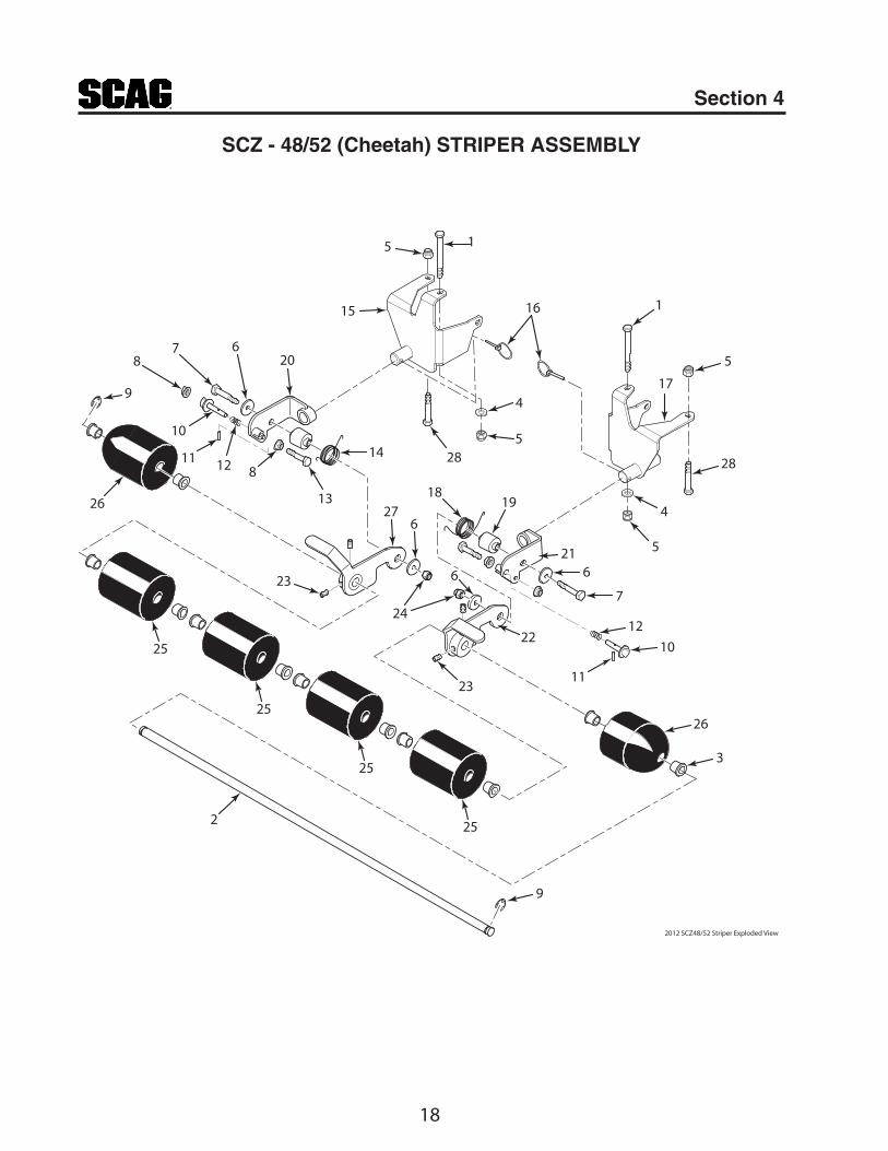
StriperModels: SZL/SFZ/SCZ48/52 STRIPER
STC/SCZ/STT STRIPER
WARNINGFAILURE TO FOLLOW SAFE OPERATING PRACTICES MAY RESULT IN
SERIOUS INJURY OR DEATH.
Read this manual completely as well as other manuals that came with your mower.•
DO NOT operate on steep slopes. To check a slope, attempt to back up it (with the •cutter deck down). If the machine can back up the slope without the wheels slipping, reduce speed and use extreme caution.
Under no circumstances should the machine be operated on slopes greater than 15 •degrees. ALWAYS FOLLOW OSHA APPROVED OPERATION.
DO NOT mow on wet grass. Wet grass reduces traction and steering control.•
Keep all shields in place, especially the grass discharge chute.•
Before performing any maintenance or service, stop the machine and remove the •spark plug wire and ignition key.
If a mechanism becomes clogged, stop the engine before cleaning.•
Keep hands, feet and clothing away from power-driven parts.•
Keep others off the mow• er (only one person at a time)
REMEMBER - YOUR MOWER IS ONLY AS SAFE AS THE OPERATOR!
HAzARD CONTROL AND ACCIDENT PREvENTION ARE DEPENDENT UPON THE AWARENESS, CONCERN, PRUDENCE, AND PROPER TRAINING OF THE PERSONNEL INvOLvED IN THE OPERATION, TRANSPORT, MAINTENANCE, AND STORAGE OF THE EqUIPMENT.
This manual covers the operating instructions and illustrated parts list for:
SzL / SFz / SCz-48/52 STRIPER with a part number of 921R
STC / SCz / STT STRIPER with a part number of 921S
Always use the model number and part number when referring to this product.
I
RTable of Contents
Table of ContentsGENERAL INFORMATIONSECTION 1 - ...................................................................................1
LIMITED WARRANTY- COMMERCIAL ACCESSORY ................................................... INSIDE BACK COvER
II
R Table of Contents
1
RSection 1
INTRODUCTION1.1
This manual has been prepared to provide the information you need to correctly assemble, operate, and maintain this Striper Accessory. Read it carefully and keep it for future reference.
THE REPLACEMENT OF ANY PART ON THIS PRODUCT BY OTHER THAN THE MANUFACTURER'S AUTHORIzED REPLACEMENT PART MAY ADvERSELY AFFECT THE PERFORMANCE, DURABILITY OR SAFETY OF THIS PRODUCT.
USE OF OTHER THAN ORIGINAL SCAG REPLACEMENT PARTS WILL vOID THE WARRANTY.
If additional information or service is needed that is not outlined in this manual, please contact your Scag Power Equipment dealer. Scag dealers are trained in the latest service methods and carry a full line of Scag replacement parts.
When ordering parts, always provide the complete model number of your Striper Accessory.
All information provided in this manual is based upon information available at the time of printing. Scag Power Equipment reserves the right to make changes at any time without notice or obligation.
DIRECTION REFERENCE1.2
The “Right” and “Left”, “Front” and “Rear” of the machine are referenced from the operator’s right and left when seated in the normal operating position and facing the forward travel direction.
SAFETY AND OPERATING 1.3 INSTRUCTIONS
note -
To avoid personal injury, it is imperative that all safety instructions be observed.
Read this operator's manual and the operator's 1. manual that is supplied with the machine this attachment is used on.
GENERAL INFORMATIONA replacement manual is available from your authorized Scag Service Dealer or by contacting: Scag Power Equipment, Service Department at P.O. Box 152, Mayville, WI 53050. You may also contact us through our website at www.scag.com The manual for this accessory can be downloaded by using the model or use the contact form to make your request. Please indicate the complete model of your Scag Accessory when requesting replacement manuals.
WARNINGDo not operate without discharge chute, mulch kit, operator controlled discharge chute (OCDC), or entire grass catcher installed.
Before removing the Striper Accessory, disengage 2. the mower, stop the engine and wait for all movement to stop.
ALWAYS3. turn the engine OFF, remove the key and wait for all movement to stop before servicing or cleaning the mower or the grass catcher.
Do not modify or alter any component of the Striper 4. Accessory or mower.
Do not allow any passengers to ride on the mower or 5. any attachments.
2
R Section 2
ASSEMBLY2.1
- note -
Use the illustrated parts list as a part number reference when fol lowing the assembly instructions.
-IMPoRtAnt-
When installing this Striper Accessory on a machine, one of the following Installation Kits must be used during installation.
*Used for SFZ61 machines with a serial number of G6800001 and Higher only.
Remove all packaging materials. Lay out the 1. mounting hardware, mounting brackets and striper assembly for easy access. Prepare the work area making sure that it is a clean, safe environment.
The following assembly instructions are specific to 2. each model this Striper Accessory is being installed on. Follow the specific instructions for your model mower.
ASSEMBLY INSTRUCTIONS -SzL / SFz2.2
Prepare the machine so there is easy and safe 1. access to the work area. Remove the key and maintain all safety related work procedures. Always wear eye and hand protection.
Using a 9/16" wrench, remove the 3/8-16 x 2-1/4" 2. hex head bolt used to secure the axle spacer to the right transaxle assembly. Be sure to retain the bolt, lockwasher and flatwasher. This hardware will be reused in step number 6. See Figure 2-1.
Remove5/16-18
HardwareAxle Spacer
Remove3/8-16 x 2-1/4”
Hex Head
Remove HardwareFigure 2-1.
Use two 1/2" wrenches to remove the 5/16-18 x 3" 3. hex head bolt, 5/16-18 x 5" hex head bolt, 5/16-18 elastic stop nuts and 5/16" flatwasher shown in Figure 2-1. Be sure to retain the flatwasher. This will be reused in step number 5.
Install the RH Striper Mounting Bracket as shown 4. in Figure 2-2. Using the new hardware provided with the Installation Kit, secure the bracket to the machine with one (1) 5/16-18 x 3-1/4" hex head bolt, one (1) 5/16-18 x 5-1/2" hex head bolt, the 5/16" flatwasher removed in step number 4 and two (2) 5/16-18 elastic stop nuts. Do not tighten this hardware at this time.
Secure the axle spacer to the transaxle assembly 5. and striper mounting bracket by reinstalling the 3/8-16 x 2-1/4" hex head bolt, 3/8" lockwasher and 3/8" flatwasher that were removed in step number 2. Torque this bolt to 39 ft. lbs. See Figure 2-2.
5/16-18 x 3-1/4”Hex Head
5/16-18Elastic Stop Nut
Removed inStep Num. 3
Removed inStep Num. 4
5/16-18Elastic Stop Nut
RH StriperMounting Bracket
Axle Spacer
Install RH Striper Mounting BracketFigure 2-2.
ASSEMBLY INFORMATION
3
RSection 2
Using the installation procedures outlined in steps 6. 2 thru 5 for the RH Striper Mounting Bracket, install and secure the LH Striper Mounting Bracket to the machine. Do not tighten the 5/16" mounting hardware at this time.
Install the Striper Roller Assembly (p/n 921R) onto 7. the mounting brackets. See Figure 2-3.
Install Roller AssemblyFigure 2-3.
Torque the 5/16" mounting hardware installed in step 8. number 5 to 19 ft. lbs.
Secure the Striper Assembly to the machine with the 9. Quick Pins supplied. See Figure 2-4.
Quick Pins
Install Quick PinsFigure 2-4.
Follow the Operating Instructions outlined in 10. Section 3 of this manual for proper operation of this accessory.
ASSEMBLY INSTRUCTIONS -STC2.3
Prepare the machine so there is easy and safe 1. access to the work area. Remove the key and maintain all safety related work procedures. Always wear eye and hand protection.
Attach the mounting brackets to the cross bar 2. between the wheel motor brackets using (2) Mounting Spacers, (4) u-bolts and (8) serrated flange nuts. See Figure 2-5. Do not tighten the hardware.
-note-
This Striper Accessory cannot be installed on an STC with a serial number below 76300001.
(4x) U-Bolts
(8x) Serrated FlangeNuts
MountingSpacer
MountingBracket
MountingSpacer
MountingBracket
Wheel MotorMounting Plate
Wheel MotorMounting Plate
Install Striper Mounting BracketsFigure 2-5.
The edge of the mounting bracket should be 3. under the wheel motor mounting plate for proper installation. See Figure 2-5.
Install the Striper Roller Assembly (p/n 921V) to the 4. mounting brackets and secure with the quick pins.
Once the Striper Roller Assembly is installed and 5. secured with the quick pins, tighten the mounting hardware on both mounting brackets.
Follow the Operating Instructions outlined in 6. Section 3 of this manual for proper operation of this accessory.
4
R Section 2
ASSEMBLY INSTRUCTIONS -SCz48/522.4
Prepare the machine so there is easy and safe 1. access to the work area. Remove the key and maintain all safety related work procedures. Always wear eye and hand protection.
Using a 9/16" wrench, remove the 3/8-16 x 2-1/4" 2. hex head bolt used to secure the axle spacer to the right transaxle assembly. Be sure to retain the bolt, lockwasher and flatwasher. This hardware will be reused in step number 6. See Figure 2-1.
Remove5/16-18
HardwareAxle Spacer
Remove3/8-16 x 2-1/4”
Hex Head
Remove HardwareFigure 2-6.
Use two 1/2" wrenches to remove the 5/16-18 x 3" 3. hex head bolt, 5/16-18 x 5" hex head bolt, 5/16-18 elastic stop nuts and 5/16" flatwasher shown in Figure 2-6. Be sure to retain the flatwasher. This will be reused in step number 5.
Install the RH Striper Mounting Bracket as shown 4. in Figure 2-7. Using the new hardware provided with the Installation Kit, secure the bracket to the machine with one (1) 5/16-18 x 3-1/4" hex head bolt, one (1) 5/16-18 x 5-1/2" hex head bolt, the 5/16" flatwasher removed in step number 3 and two (2) 5/16-18 elastic stop nuts. Do not tighten this hardware at this time.
Secure the axle spacer to the transaxle assembly 5. and striper mounting bracket by reinstalling the 3/8-16 x 2-1/4" hex head bolt, 3/8" lockwasher and 3/8" flatwasher that were removed in step number 2. Torque this bolt to 39 ft. lbs. See Figure 2-7.
5/16-18 x 3-1/4”Hex Head
5/16-18Elastic Stop Nut
Removed inStep Num. 3
Removed inStep Num. 4
5/16-18Elastic Stop Nut
RH StriperMounting Bracket
Axle Spacer
Install RH Striper Mounting BracketFigure 2-7.
Using the installation procedures outlined in steps 6. 2 thru 5 for the RH Striper Mounting Bracket, install and secure the LH Striper Mounting Bracket to the machine. Do not tighten the 5/16" mounting hardware at this time.
Install the Striper Roller Assembly (p/n 921R) onto 7. the mounting brackets. See Figure 2-8.
Install Roller AssemblyFigure 2-8.
Torque the 5/16" mounting hardware installed in step 8. number 5 to 19 ft. lbs.
Secure the Striper Assembly to the machine with the 9. Quick Pins supplied. See Figure 2-9.
5
RSection 2
Quick Pins
Install Quick PinsFigure 2-9.
Follow the Operating Instructions outlined in 10. Section 3 of this manual for proper operation of this accessory.
ASSEMBLY INSTRUCTIONS -SCz61/722.5
Prepare the machine so there is easy and safe 1. access to the work area. Remove the key and maintain all safety related work procedures. Always wear eye and hand protection.
Attach the mounting brackets to the double cross bar 2. between the hydraulic axle mounting plates using (8) u-bolts and (16) serrated flange nuts. See Figure 2-10. Do not tighten the hardware.
(16x) Serrated FlangeNuts
L.H. MountingBracket
R.H. MountingBracket
(8x) U-Bolts
Mounting Bracket InstallFigure 2-10.
Slide the mounting brackets outward to the edge of 3. the axle motor mounting plates. Do not tighten the hardware. See Figure 2-11.
Mounting Bracket PositionFigure 2-11.
Install the Striper Roller Assembly (p/n 921V) to the 4. mounting brackets and secure with the quick pins. See Figure 2-12.
6
R Section 2
Install Roller AssemblyFigure 2-12.
Once the Striper Roller Assembly is installed and 5. secure, tighten the mounting hardware on both mounting brackets.
Follow the Operating Instructions outlined in 6. Section 3 of this manual for proper operation of this accessory.
ASSEMBLY INSTRUCTIONS -STT2.6
Prepare the machine so there is easy and safe 1. access to the work area. Remove the key and maintain all safety related work procedures. Always wear eye and hand protection.
Attach the mounting brackets to the cross bar 2. between the wheel motor brackets using (4) u-bolts and (8) serrated flange nuts. See Figure 2-13. Do not tighten the hardware.
-note-
If the Tiger Striper is installed on an STT with a serial number below 7219999, part number 423966 mounting spacer will need to be installed between the mounting bracket and cross bar. See Figure 2-13.
STT with a serial number of 7219999 or Below
(4x) U-Bolts
(8x) Serrated FlangeNuts
(4x) U-Bolts
(8x) Serrated FlangeNuts
MountingBracket
MountingBracket
MountingSpacer
MountingSpacer
MountingBracket
MountingBracket
Mounting Bracket InstallFigure 2-13.
The edge of the mounting bracket should be 3. under the wheel motor mounting plate for proper installation. See Figure 2-13.
Install the left and right hand Striper Stop Brackets 4. (p/n 423953 & p/n 423954) to the frame and secure with (4) 3/8-16 x 1" bolts and (4) elastic stop nuts. See Figure 2-14.
423953 L.H.Stop Bracket
423954 R.H.Stop Bracket
(4) 3/8-16 x 1" Bolt
(4) 3/8-16 ElasticStop Nut
Install Striper Stop BracketsFigure 2-14.
7
RSection 2
Install the Striper Roller Assembly (p/n 921V) to the 5. mounting brackets and secure with the quick pins.
Once the Striper Roller Assembly is installed and 6. secure, tighten the mounting hardware on both mounting brackets.
Follow the Operating Instructions outlined in 7. Section 3 of this manual for proper operation of this accessory.
8
R Section 3
OPERATING INSTRUCTIONS3.1
To operate the Striper Accessory, you will need to lower the roller to the operating position. The Striper can be easily removed or locked in the transport position whenever the machine is being transported or when striping is not needed.
To unlock the Striper from the transport position, lift 1. up slightly on the handle and turn the lock pin until the small roll pin lines up with the slot. See Figure 3-1.
Roll Pin
Push and Turn Pin to line up Roll Pin with Slot to Unlock
Lift Up onHandle
Unlocking the Stripe RollerFigure 3-1.
Repeat this procedure on the opposite side.2.
The Stripe Roller is now ready to operate.
LAWN STRIPING3.2
HOW DOES LAWN STRIPING WORK?
The “stripe” that you see on the lawn is actually light reflecting off the blades of grass. The direction in which the grass is bent determines the “light” or “dark” stripe. When the blades of grass are bent away from you, the grass appears lighter in color because light is reflecting off of the length of the blade. When the blades of grass are bent towards you, the stripe appears darker as you are looking at more of the tips of the blades (a smaller reflective surface) and the shadows under the blades of grass. Cutting a lawn in the up/down, north/south, east/west, opposing directions provides the best stripe effect.
You may find that certain grasses have a more noticeable stripe (stripe easier) than others. Cutting the grass at a different height can sometimes change the intensity of the stripe. A slightly higher cut (example: 3" versus 2.5") can provide more grass to be bent over, thus producing a more noticeable stripe. In some types of grass, this may have the opposite or no effect.
Grass that tends to be "stiff" and resists bending will not yield a stripe as well as a softer grass that bends easily.
Note that you do not need to cut the grass in order to stripe it. The roller simply needs to be in the unlocked/engaged position. You may find that when creating more advanced, overlapping striping patterns, you can complete the job faster by applying the overlaying stripes without the blades engaged.
Striping can be used to draw attention to particular landscape features. It can be used to further enhance the finished, manicured cut that your Scag mower delivers.
LAWN STRIPING GUIDELINES3.3
A stripe pattern can add richness and depth to any lawn. Here are some guidelines to help produce various patterns and to enhance your striping techniques.
BASIC STRIPE PATTERN:
Begin by mowing the perimeter around the property (Reference Figure 3-2). Next, mow in opposing directions through the remaining property (as shown in Figure 3-2). Take care when turning at the end of each row to prevent turf damage. A simple "Y" type turn at the end of each row will reduce the chance of turf damage while setting the mower up for the next row to be mowed.
Finish the job by mowing the perimeter again. This will remove any stripe pattern irregularities left from turning at the end of each row and delivers a finished look.
Basic Stripe PatternFigure 3-2.
OPERATING INFORMATION
9
RSection 3
CHECKERBOARD" PATTERN:
Begin by mowing the perimeter around the property (Reference Figure ). Next, mow in opposing directions (North and South or East and West) through the remaining portion of the property (as shown in Figure 3-3). Take care when turning at the end of each row to prevent turf damage. A simple "Y" type turn at the end of each row will reduce the chance of turf damage while setting the mower up for the next row to be mowed. Now, travel in the opposite direction of the original mowing pattern (if you were mowing North and South, now mow East and West, etc). Reference Figure 3-3.
Finish the job by mowing the perimeter again. This will remove any stripe pattern irregularities left from turning at the end of each row and delivers a finished look.
Checkerboard PatternFigure 3-3.
"DIAGONAL OR CRISS-CROSS" PATTERN:
This pattern is achieved using the same techniques as the "Checkerboard" pattern. Simply apply the stripes in a diagonal direction. See Figure 3-4.
Diagonal PatternFigure 3-4.
REMOvING THE STRIPE ROLLER3.4
The Stripe Roller can be easily removed whenever the machine is being transported or when striping is not needed. To remove the Striper, follow the instructions below.
- note -
The Stripe Roller is removed the same way for all models. For pictoral clarity purposes, only the SCZ model is shown..
Prepare the machine so there is easy and safe 1. access to the work area. Remove the key and maintain all safety related work procedures. Always wear eye and hand protection.
Lock the Stripe Roller up in the transport position by 2. lifting upward on the handle, push and turn the lock pin 90 degrees. The small roll pin must be out of the slot in the bracket to lock in the transport position. See Figure 3-5.
Push andTurn Pin to Lock
Roll Pin
Locking Roller in transport PositionFigure 3-5.
Repeat on opposite side.3.
Once the Stripe Roller is locked in the transport 4. position, remove the quick pins securing the Stripe Roller to the mounting brackets. See Figure 3-6.
10
R Section 3
Quick Pins
Removing Stripe RollerFigure 3-6.
Slide the Stripe Roller off of the mounting brackets.5.
To install the Stripe Roller, slide the assembly on 6. to the mounting brackets and reinstall the quick pins. Once the Stripe Roller has been reinstalled, follow Section 3.1 Operating Instructions for proper operation.
Any part of the Scag commercial accessory manufactured by Scag and found, in the reasonable judgment of Scag, to be defective in material or workmanship, will be repaired or replaced by an Authorized Scag Service Dealer without charge for parts and labor.
The Scag accessory, including any defective part, must be returned to an Authorized Scag Service Dealer within the warranty period. The expense of delivering the accessory to the dealer for warranty work and the expense of returning it back to the owner after repair or replacement will be paid for by the owner. Scag’s responsibility in respect to claims is limited to making the required repairs or replacements, and no claim of breach of warranty shall be cause for cancellation or rescission of the contract of sale of any Scag machine. Proof of purchase will be required by the dealer to substantiate any warranty claim. All warranty work must be performed by an Authorized Scag Service Dealer.
This warranty is limited to 90 days from the date of original retail purchase for any Scag accessory that is used for commercial purposes, or any other income-producing purpose including rental use.
The warranty for the grass catcher blower assemblies (excluding the belt) is limited to 1-year from the date of original retail purchase. 90 Days for rental use.
This warranty does not cover any accessory that has been subject to misuse, neglect, negligence, or accident, or that has been operated in any way contrary to the operating instructions as specified in the Operator's Manual. The warranty does not apply to any damage to the accessory that is the result of improper maintenance, or to any accessory or parts that have not been assembled or installed as specified in the Operator's Manual.
The warranty does not cover any accessory that has been altered or modified. In addition, the warranty does not extend to repairs made necessary by normal wear, or by the use of parts or accessories which, in the reasonable judgment of Scag, are either incompatible with the Scag mower or adversely affect its operation, performance or durability. This warranty does not cover engines and electric starters, which are warranted separately by their manufacturer.
Scag Power Equipment reserves the right to change or improve the design of any accessory without assuming any obligation to modify any accessory previously manufactured.
All other implied warranties are limited in duration to the 90 day warranty period. Accordingly, any such implied warranties including merchantability, fitness for a particular purpose, or otherwise, are disclaimed in their entirety after the expiration of the appropriate ninety day warranty period. Scag’s obligation under this warranty is strictly and exclusively limited to the repair or replacement of defective parts and Scag does not assume or authorize anyone to assume for them any other obligation. Some states do not allow limitations on how long an implied warranty lasts, so the above limitation may not apply to you.
Scag assumes no responsibility for incidental, consequential or other damages including, but not limited to, expense for gasoline, oil, expense of delivering the machine to an Authorized Scag Service Dealer and expense of returning it back to the owner, mechanic’s travel time, telephone or telegram charges, rental of a like product during the time warranty repairs are being performed, travel, loss or damage to personal property, loss of revenue, loss of use of the mower, loss of time, or inconvenience. Some states do not allow the exclusion or limitation of incidental or consequential damages, so the above limitation or exclusion may not apply to you.
This warranty gives you specific legal rights, and you may also have other rights which vary from state to state.