TC 3 Edition 04.17 AGA Product brochure · GB Tightness controls • Adjustable test period which can be adapted to different systems • Adjustable test instant allows quick system start • Maximum safety thanks to self-monitoring electronics
Transcript
TC
3 Edition 04.17
AGA
Product brochure · GB
Tightness controls• Adjustable test period which can be adapted to different
systems
• Adjustable test instant allows quick system start
• Maximum safety thanks to self-monitoring electronics
2 · TC · Edition 04.17
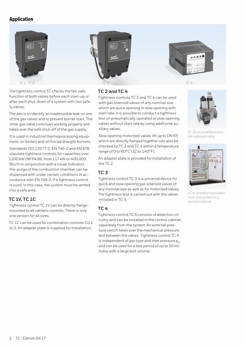
TC 1, TC 2 TC 3 TC 4
Application
The tightness control TC checks the fail-safe function of both valves before each start-up or after each shut-down of a system with two safe-ty valves.
The aim is to identify an inadmissible leak on one of the gas valves and to prevent burner start. The other gas valve continues working properly and takes over the safe shut-off of the gas supply.
It is used in industrial thermoprocessing equip-ment, on boilers and on forced draught burners.
Standards ISO 13577-2, EN 746-2 and EN 676 stipulate tightness controls for capacities over 1200 kW (NFPA 86: from 117 kW or 400,000 Btu/h in conjunction with a visual indicator). Pre-purge of the combustion chamber can be dispensed with under certain conditions in ac-cordance with EN 746-2, if a tightness control is used. In this case, the system must be vented into a safe area.
TC 1V, TC 1CTightness control TC 1V can be directly flange-mounted to all valVario controls. There is only one version for all sizes.
TC 1C can be used for combination controls CG 1 to 3. An adapter plate is supplied for installation.
TC 2 and TC 4Tightness controls TC 2 and TC 4 can be used with gas solenoid valves of any nominal size, which are quick opening or slow opening with start rate. It is possible to conduct a tightness test on pneumatically operated or slow opening valves without start rate by using additional au-xiliary valves.
Slow opening motorized valves VK up to DN 65 which are directly flanged together can also be checked by TC 2 and TC 4 within a temperature range of 0 to 60°C (32 to 140°F).
An adapter plate is provided for installation of the TC 2.
TC 3Tightness control TC 3 is a universal device for quick and slow opening gas solenoid valves of any nominal size as well as for motorized valves. The tightness test is carried out with the valves installed in TC 3.
TC 4Tightness control TC 4 consists of detection cir-cuitry and can be installed in the control cabinet, separately from the system. An external pres-sure switch takes over the mechanical pressure test between the valves. Tightness control TC 4 is independent of gas type and inlet pressure pu and can be used for a test period of up to 10 mi-nutes with a large test volume.
TC 1V on a valVario dou-ble solenoid valve
TC 4 installed separately from the system in a control cabinet
TC · Edition 04.17 · 3
V1 V2
VADVAS
PZ
pu pz
VP
TC 1V
pu2
TC 1V
OK
9
V2V1
GFA
V1
pu2
CG
V1 V2
PZ
pu pz
TC 1C
PZ
VP
TC 1C
9
OK
GFA
Application examplesPZ = Internal pressure sensor of the TC for the
comparison of inlet pressure pu and inter-space pressure pz
pd = Outlet pressure
VP = Test volume
TC 1V with valVario controlsMains voltage = control voltage V1: quick or slow opening valve with start rate. V2: pressure regulator with solenoid valve.
Tightness control TC 1V checks gas solenoid valves V1 and V2 and the pipe between the valves for tightness. If both valves are tight, the TC forwards the OK enable signal to the automa-tic burner control unit GFA. This opens valves V1 and V2 simultaneously. The burner starts.
TC 1C with combination control CG..D or CG..VMains voltage = control voltage V1 and V2: quick opening valves.
TC 1C is directly flange-mounted to combination control CG..D or CG..V and checks gas solenoid valves V1 and V2 in the combination control for tightness.
Once the tightness test has been carried out successfully, the tightness control forwards the OK enable signal to the automatic burner control unit GFA. This opens valves V1 and V2 in the combination control CG simultaneously. The burner starts.
4 · TC · Edition 04.17
TC 2 with two gas solenoid valvesMains voltage = control voltage V1 and V2: quick or slow opening valves with start rate.
TC 2 checks gas solenoid valves V1 and V2 and the pipe between the valves for tightness. If both valves are tight, the TC forwards the OK enable signal to the automatic burner control unit GFA. This opens valves V1 and V2 simulta-neously. The burner starts.
V2V1
pu2
V1 V2
PZ
pu pz
TC 2
VP
TC 2
9
OK
GFA
GFAV1
pu2
V1 V2
PZ
pu pz
TC 2V3
VP
TC 2
OK
V2
9
V3
TC 2 with two gas solenoid valves and one auxiliary valve for dischargeMains voltage = control voltage V1 and V2: quick or slow opening valves with start rate. V3: quick or slow opening valve with start rate, nominal size is dependent on test volume VP and inlet pressure pu, but is at least DN 15.
TC 2 checks gas solenoid valves V1, V2, the au-xiliary valve V3 and the pipe between the valves for tightness. It must be ensured that the interspace pz is vented during the 3-second opening time. This is not guaranteed by the gas pressure regula-tor downstream of V2. A relief line is thus used to discharge the test volume VP safely into the combustion chamber or into a safe area. Auxilia-ry valve V3 can also be used as a pilot gas valve. Since valve V2 remains closed during the test, it can also be a slow opening motorized valve VK. Once the tightness test has been carried out successfully, the tightness control forwards the OK enable signal to the automatic burner control unit GFA. The GFA opens the gas solenoid valves V1 and V2 simultaneously. The burner starts.
TC · Edition 04.17 · 5
pu2
V1 V2
PZ
pu pz
TC 2
V3
VP
GFAV1
TC 2
OK
9
V3
V2
TC 2 with two gas solenoid valves and one auxiliary valve for dischargeMains voltage = control voltage V1: quick or slow opening valve with start rate. V2: any. V3: quick opening, nominal size is dependent on test volume VP and inlet pressure pu, but is at least DN 15.
TC 2 checks gas solenoid valves V1, V2, the au-xiliary valve V3 and the pipe between the valves for tightness. If all the gas solenoid valves are tight, the tight-ness control forwards the OK enable signal to the automatic burner control unit GFA. The GFA opens the gas solenoid valves V1 and V2 simul-taneously. The burner starts. A relief line is used to discharge the test volume VP into a safe area. Thanks to the installed auxili-ary valve V3, valve V2 can also be a slow opening motorized valve VK.
V2V1
pu2
V1 V2
PZ
pu pz
TC 2
K1
DG VAS
VAS
V3
V4
VAS
DG
VAS
PZ
VP
TC 2
OK
K1
V1
V2
9
TC 2 in a multiple burner system with several valves installed in seriesMains voltage = control voltage
V3 and V4: quick opening, nominal size is depen-dent on test volume VP and inlet pressure pu, but is at least DN 15.
When using slow opening main valves (V1 and V2), auxiliary valves (V3 and V4) must be used for the supply and discharge of the test volu-me VP. TC 2 checks the central shut-off valve V1, the gas solenoid valve V2, the auxiliary valves V3 and V4 and the pipe between these valves for tightness. Valve V2 can only be checked for tightness when the pressure downstream of V2 approximately corresponds to the atmospheric pressure and the volume downstream of valve V2 is 5 x VP. The gas solenoid valve VAS and the pressure switch DGVAS are used to relieve the pressure. The pressure switch must be adjusted in such a way so that enough pressure is relieved and no air can get into the pipework. Once the tightness test has been carried out successfully, TC 2 opens the main valves V1 and V2 with the OK enable signal and enables the downstream burner control units.
6 · TC · Edition 04.17
TC 3 in a multiple burner system with several valves installed in seriesV1 and V2: any.
TC 3 checks slow opening main valves V1 and V2 and the pipe between these valves for tightness. The test volume VP is supplied and discharged via the TC 3 auxiliary valves. Valve V2 can only be checked for tightness when the pressure downstream of V2 approximately corresponds to the atmospheric pressure and the volume downstream of valve V2 is 5 x VP. The gas solenoid valve VAS and the pressure switch DGVAS are used to relieve the pressure. The pressure switch must be adjusted in such a way so that enough pressure is relieved and no air can get into the pipework.
Once the tightness test has been carried out successfully, TC 3 opens the main valves V1 and V2 with the OK enable signal and enables the downstream burner control units.
K1
DG VAS
VAS
VAS
DG
VAS
PZ
TC 3
OK
9
V1 V2
pu pz
VP
PZ
TC 3
pu2
pu pd
K1
V1
V2
1 2 3 4 5 6 7 8 9 10 111213
OK
L1(+)N(-)
TC 4
pu2
V1
V1
V2
V2
pu
PZ
TC 4
pz
VP
PZ
DG
GFA
TC 4 with two gas solenoid valvesV1 and V2: quick or slow opening valves with start rate.
TC 4 checks gas solenoid valves V1 and V2 and the pipe between the valves for tightness. The external pressure switch DG monitors the pressure between the two valves. Once the tightness test has been carried out successfully, TC 4 forwards the OK enable signal to the automatic burner control unit GFA. The GFA opens the gas solenoid valves V1 and V2 simultaneously. The burner starts.
TC · Edition 04.17 · 7
1 2 3 4 5 6 7 8 9 10 111213
OK
L1(+)N(-)
TC 4
V1
V3V2
V1 V2
pu pz
V3pu2
PZDG
TC 4
ϑ
VP
PZ
GFA
TC 4 with two gas solenoid valves and one auxiliary valve for dischargeV1: quick or slow opening valve with start rate. V2: any. V3: quick opening, nominal size is dependent on
test volume VP and inlet pressure pu, but is at least DN 15.
TC 4 checks gas solenoid valves V1, V2, the au-xiliary valve V3 and the pipe between the valves for tightness. It must be ensured that the interspace pz is vented during the 2-second opening time. This is not guaranteed by the gas pressure regulator downstream of V2. A relief line is thus used to di-scharge the test volume VP safely into the com-bustion chamber or into a safe area. Since valve V2 remains closed during the test, it can also be a slow opening motorized valve VK. If all the gas solenoid valves are tight, TC 4 for-wards the OK enable signal to the automatic burner control unit GFA. The GFA opens the gas solenoid valves V1 and V2 simultaneously. The burner starts.
pz
pu2
OK
L1(+)N(-)
TC 4
1 2 3 4 5 6 7 8 9 10 111213
V1
pu
V3
V2
TC 4
V3
V2V1
PZ
VP
DG
PZ
TC 4 in a multiple burner system with two auxiliary valves for supply and dischargeV1: any. V2 and V3: quick opening, nominal size is depen-dent on test volume VP and inlet pressure pu, but is at least DN 15.
TC 4 checks the central shut-off valve V1, the auxiliary valves V2 and V3, the burner valves and the pipe between these valves for tightness. The test volume VP is supplied via the auxiliary valve V3. The external pressure switch DG monitors the pressure between the gas solenoid valves V1, V2 and the burner valves. Once the tightness test has been carried out successfully, TC 4 opens gas solenoid valve V1. The TC forwards the OK enable signal simulta-neously to the automatic burner control units for the burner valves. The burner valves open and the burners start. Thanks to the relief line and auxiliary valve V2, the test volume VP is discharged into a safe area or into the combustion chamber.
8 · TC · Edition 04.17
pu2
OK
L1(+)N(-)
TC 4
K1
k1
VAS
1 2 3 4 5 6 7 8 9 10 111213
DGVASk1
V1 V2
pu
TC 4
V1
V2
VAS
PZ
DG
VAS
pz
VP
PZ
PZDG
TC 4 in a multiple burner system with several valves installed in seriesV1 and V2: quick or slow opening valves with start rate.
Tightness control TC 4 checks the central shut-off valve V1, the gas solenoid valve V2 and the pipe between these valves for tightness. Valve V2 can only be checked for tightness when the pressure downstream of V2 approximately corresponds to the atmospheric pressure. The gas solenoid valve VAS and the pressure switch DGVAS are used to relieve the pressure. The pressure switch must be adjusted in such a way so that enough pressure is relieved and no air can get into the pipework. After the thermostat/start-up signal ϑ has been applied, first DGVAS is checked. If the pressure downstream of V2 is correct, the VAS closes and the tightness test is started. Once the tightness test has been carried out successfully, TC 4 opens the main valves V1 and V2 with the OK enable signal and enables the downstream burner control units.
TC · Edition 04.17 · 9
Technical data
TC 1, TC 2, TC 3
Electrical dataMains voltage and control voltage: 120 V AC, -15/+10%, 50/60 Hz, 230 V AC, -15/+10%, 50/60 Hz, 24 V DC, ±20%.
Power consumption (all LEDs green): 5.5 W at 120 V AC and 230 V AC, 2 W at 24 V DC, TC 3: plus 8 VA for an auxiliary valve.
Fine-wire fuse: 5 A, slow-acting, H, 250 V, pursu-ant to IEC 60127-2/5, F1: protection of valve outputs (terminals 15 and 16), fault signal (terminal 12) and supply of the control inputs (terminals 2, 7 and 8). F2: protection of safety interlock/controller ena-ble signal (terminal 6).
The input current at terminal 1 must not exceed 5 A.
Max. load current (terminal 6) for safety inter-lock/controller enable and valve outputs (termi-nals 15 and 16): at 230/120 V AC mains voltage, max. 3 A resistive load; at 24 V DC mains voltage, max. 5 A resistive load.
External fault signal (terminal 12): fault output at 120 V AC/230 V AC/24 V DC mains and control voltage: max. 5 A, fault output at 120 V AC/230 V AC mains volta-ge, 24 V DC control voltage: max. 100 mA.
TC switching cycles: 250,000 pursuant to EN 13611.
Reset: using a button on the device or by remote reset.
EnvironmentGas type: natural gas, town gas, LPG (gaseous), biogas (max. 0.1 %-by-vol. H2S) and air.
The gas must be clean and dry in all temperature conditions and must not contain condensate.
Inlet pressure pu: 10 to 500 mbar (3.9 to 195 „WC).
Measurement time tM: 5 to 30 s, adjustable. Set at the factory to 30 s.
Medium and ambient temperatures: -20 to +60°C (-4 to +140°F). No condensation permitted.
Long-term use in the upper ambient tempera-ture range accelerates the ageing of the elasto-mer materials and reduces the service life.
Storage temperature: -20 to +40°C (-4 to +104°F).
Mechanical dataLength of connection cable: at 230 V AC/120 V AC: any, at 24 V DC (supply connected to PE): max. 10 m permitted, at 24 V DC (supply not connected to PE): any.
For quick opening individual valvesFor quick or slow opening valves
RN
With Rp internal threadWith NPT internal thread
05 pu max. 500 mbar
WQK
Mains voltage:230 V AC, 50/60 Hz120 V AC, 50/60 Hz
24 V DC
/W/Q/K
Control voltage:230 V AC, 50/60 Hz120 V AC, 50/60 Hz
24 V DC
TC 4
Code DescriptionTC Tightness control4 In control cabinet1 Testing before or after burner run0 External pressure switch required
-1-10
Test period:10 – 60 s
100 – 600 s
TNK
Mains voltage:220/240 V AC, 50/60 Hz110/120 V AC, 50/60 Hz
24 V DC=
Maintenance cyclesTightness controls TC require little servicing. We recommend carrying out a function check once a year or twice a year in the case of biogas.
12 · TC · Edition 04.17 03
25
06
30
Technical Information bulletin for this productwww.docuthek.com Search term: TC