25
Tiles ™ Installation Manual Complete instructions to install the Friant Tiles ™ panel system

Tiles™ Installation Manual
Complete instructions
to install the Friant
Tiles™ panel system

Page 2Tiles™ Installation Manual
Introduction ........................................................................................................................................................... 3
Tile Assembly, Frames, Connectors, and Change of Height Wedge Installation ............................................................................................................ 4
Tiles Assembly, Frames, Connectors, and Change of Height Wedge Installation ............................................... 5
Connectors Cover, Finished End Cover, Finished End Change of Height Cover, Installation .................................................................................................................... 6
Stacking Frame, and Stacking Connector Installation .......................................................................................... 7
8-Wire Electrical, Base Feed Installation .............................................................................................................. 8
8-Wire Electrical, Base Power Retro, and Beltline Power Retro Installation .................................................................................................................... 9
8-Wire Electrical, Beltline Power Retro Duplex Clip Installation ........................................................................... 10
8-Wire Electrical, In-Frame Power Jumper and Pass-Through Power Jumper Installation ...................................................................................................... 11
8-Wire Electrical, Beltline Power Transfer Installation .......................................................................................... 12
Fabric Tiles, Marker Board Tiles, Perforated Tiles, and Window Tiles Installation ............................................................................................................................... 13
Rail Tiles, Power and Data Tiles Installation ........................................................................................................ 14
Shelf Ends and Shelf Installation .......................................................................................................................... 15
Flipper Door Unit Door/Cover Installation ............................................................................................................. 16
Worksurface Installation ....................................................................................................................................... 17
Worksurface Installation ....................................................................................................................................... 18
Worksurface Installation ....................................................................................................................................... 19
Transaction Surfaces Installation ......................................................................................................................... 20
Worksurface Support End Panels, and Half Leg Installation ................................................................................ 21
Open Metal Worksurface Support Installation ...................................................................................................... 22
Door Frame Installation ........................................................................................................................................ 23
Supporting Pedestals and Lateral Files Installation .............................................................................................. 24
Table of Contents

Page 3Tiles™ Installation Manual
The Tiles™ System is composed of full and/or partial height Walls, Support Cabinets, Wall Mounted and Free-Standing components, and accessories.
The Tiles™ System is consid-ered to be portable furniture; therefore, subject to applicable local Fire, Electrical and Building Codes. Check with local authori-ties prior to installation.
Electrical Statement:
Friant’s Tiles™ System Electrical Distribution System is listed with the Underwriters Laboratories, and complies with the National Electrical Code, ANSI/BIFMA 70. Check with local authorities prior to installing the product.
Tiles™ System Installation ManualIntroductionThe Tiles™ System Installation manual provides the necessary instruction for the safe installation of the Tiles™ System for:
• The Installers with visual and written instructions.• The End Users to ensure continued safe use of the product when maintaining and reconfiguring the product.
To ensure proper installation of the product, the Tiles™ System requires layout and wall supports as specified in this manual. Reconfiguration of the product and additions to an installation must be performed per the instructions in this manual to ensure the continued safe use of the product. Friant & Associates, LLC does not assume any responsibility for product that is altered in any way.
WARNING:
Failure to follow the instructions in this manual can result in product damage, personal injury, or death.

Page 4Tiles™ Installation Manual
Tile Assembly, Frames, Connectors, and Change of Height Wedge Installation
Notched Tab
Notched Tab
Draw Rod
Draw Rod
Post
Cap Screw
Cap Screw
Frame
Frame
Frames of Equal Heights1. Connect Draw Rod to the first frame by
inserting the bottom hook on Draw Rod into rectangular opening at the bottom of the frame. Loosen Cap Screw, so it lines up with Notched Tab at the top of the Frame.
2. Lift second Frame to engage bottom hook on the Draw Rod to the rectangular opening at the bottom of the second Frame.
3. Position Frames so that notched Tab on one is fitted between shoulders of adjacent Cap Screw of Draw Rod.
NOTE: Be sure that the Glides are all the way in at the bottom of the Frame. If floor is very uneven, Glide adjustment should be made during assembly of product.
4. Tighten Cap Screw until stiles come together.
Frame to Connector of Equal Height1. To connect a Frame to a Connector of
equal height, you need a Draw Rod of the same height.
2. Connect Draw Rod to the Connector by inserting the bottom hook on Draw Rod into rectangular opening at the bottom of of the Connector. Loosen Cap Screw, so it lines up with the Notched Tab at the top of the Connector.
3. Position Frame so that notched Tab on the Frame is fitted between shoulders of adjacent Cap Screw of Draw Rod. Hold Frame against Connector and tighten Cap Screw until Frame and Connector come together.
Page 5Tiles™ Installation Manual
Frame
Change of
Height Wedge
Change of
Height Wedge
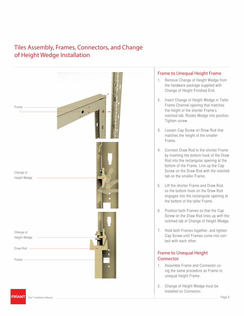
Frame to Unequal Height Frame1. Remove Change of Height Wedge from
the hardware package supplied with Change of Height Finished End.
2. Insert Change of Height Wedge in Taller Frame Channel opening that matches the height of the shorter Frame’s notched tab. Rotate Wedge into position. Tighten screw.
3. Loosen Cap Screw on Draw Rod that matches the height of the smaller Frame.
4. Connect Draw Rod to the shorter Frame by inserting the bottom hook of the Draw Rod into the rectangular opening at the bottom of the Frame. Line up the Cap Screw on the Draw Rod with the notched tab on the smaller Frame.
5. Lift the shorter Frame and Draw Rod, so the bottom hook on the Draw Rod engages into the rectangular opening at the bottom of the taller Frame.
6. Position both Frames so that the Cap Screw on the Draw Rod lines up with the notched tab of Change of Height Wedge.
7. Hold both Frames together, and tighten Cap Screw until Frames come into con-tact with each other.
Frame to Unequal Height Connector1. Assemble Frame and Connector us-
ing the same procedure as Frame to unequal height Frame.
2. Change of Height Wedge must be installed on Connector.
Tiles Assembly, Frames, Connectors, and Change of Height Wedge Installation
Draw Rod
Frame

Page 6Tiles™ Installation Manual
Rectangular Slot
Extended Tab
Connector
Connector Cover
Finished End
Frame
Extended Tabs
Finished End Change of Height
Connector Covers, and Finished End Covers1. Position the Covers onto the Frame
Channel so that the extended Tabs pass through the rectangular slots on the side of the Frame or Connector.
2. Hold the Cover tight against the Frame or Connector, and slide the Cover down until the top of the Cover is flush with the Frame Top Cap or Connector Top Cap.
3. To remove, hold the bottom of the Cover, and pull up until it disengages from Frame or Connector.
Change of Height Finished End
WARNING:A Change of Height Wedge must be installed when two Frames or Connectors of unequal height are connected.
Frame Top Cap must be in place prior to installing Finished End Change of Height.
Connectors Cover, Finished End Cover, Finished End Change of Height Cover, Installation
1. Hold the Cover tight against the Frame or Connector, and slide the Cover down until the top of the Cover is flush with the Frame Top Cap or Connector Top Cap.
2. To remove, hold the bottom of the Cover, and pull up until it disengages from Frame or Connector.
WARNING: If the Connector Cover, Finished End or Change of Height Finished End does not sit flush with the top of the Frame or Con-nector, remove the Cover and adjust the Extended Tabs until the Cover sits flush.
3. Do not use a rubber mallet to force the Cover down.
Page 7Tiles™ Installation Manual
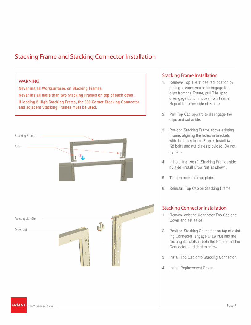
Stacking Frame Installation1. Remove Top Tile at desired location by
pulling towards you to disengage top clips from the Frame, pull Tile up to disengage bottom hooks from Frame. Repeat for other side of Frame.
2. Pull Top Cap upward to disengage the clips and set aside.
3. Position Stacking Frame above existing Frame, aligning the holes in brackets with the holes in the Frame. Install two (2) bolts and nut plates provided. Do not tighten.
4. If installing two (2) Stacking Frames side by side, install Draw Nut as shown.
5. Tighten bolts into nut plate.
6. Reinstall Top Cap on Stacking Frame.
Stacking Frame and Stacking Connector Installation
WARNING: Never install Worksurfaces on Stacking Frames.
Never install more than two Stacking Frames on top of each other.
If loading 2-High Stacking Frame, the 900 Corner Stacking Connector and adjacent Stacking Frames must be used.
Rectangular Slot
Stacking Frame
Draw Nut
Bolts
Stacking Connector Installation1. Remove existing Connector Top Cap and
Cover and set aside.
2. Position Stacking Connector on top of exist-ing Connector, engage Draw Nut into the rectangular slots in both the Frame and the Connector, and tighten screw.
3. Install Top Cap onto Stacking Connector.
4. Install Replacement Cover.

Page 8Tiles™ Installation Manual
Base Feed Housing
Base Feed
Base Feed
Base Feed
All electrical connections to the
building electrical sources must be
wired by a licensed electrician.
WARNING:Disconnect power before servicing.
WARNING:All electrical connections must be fully engaged and locked. A loose connection can cause fire and/or electrical shock.
Base Power Entry, Direct Connect1. The Base Power Entry plugs directly into
a Power Retro assembly at a Duplex Outlet connection point.
2. Locate the appropriate connecting point on the Frame. The Base Cover must be opened to allow access.
3. Pass the Flex Conduit through the Base Cover closest to the connecting point. Place the Base Feed housing into posi-tion, and slide between the brackets toward the connection assembly. Ensure that the Connector is fully engaged. Press further until the spring tab clicks into position.Return the Base Cover to the closed position.
4. Return the Base Cover to the closed position.
8-Wire Electrical, Base Feed Installation

Page 9Tiles™ Installation Manual
8-Wire Electrical, Base Power Retro, and Beltline Power Retro Installation
Frame
Frame
Frame
Self Tapping Screws
Support Bar
Support Bar
Power Retro
Power Retro
Festoon
Bottom Rail
WARNING:Disconnect power before servicing.
WARNING:All electrical connections must be fully engaged and locked. A loose connection can cause fire and/or electrical shock.
Baseline Power Retro1. Place Baseline Power Retro over Bot-
tom Rail and line up holes in the Power Retro mounting bracket with the holes in the Bottom Rail.
2. Secure with the Self Tapping Screws provided and tighten securely.
3. Connect Festoon to the Power Retro.
Beltline Power Retro1. Install Support Bar at the desired height,
and secure with Self Tapping Screws provided on both sides of the Frame.
2. Place Baseline Power Retro over Support Bar and line up holes in the Power Retro mounting bracket with the holes in the Support Bar.
3. Secure with the Self Tapping Screws provided and tighten securely.
4. Connect Festoon to the Power Retro.

Page 10Tiles™ Installation Manual
8-Wire Electrical, Beltline Power Retro Duplex Clip Installation
Duplex Clip Installation1. Insert Clip at an angle into slits on top of
the Beltline Power Support Bar.
2. Straighten Clip and slide Clip, either left or right, over the Duplex Outlet.
Duplex Outlet
Duplex Outlet
Beltline Power Support Bar
Beltline Power Support Bar
Clip
Clip

Page 11Tiles™ Installation Manual
8-Wire Electrical, In-Frame Power Jumper and Pass-Through Power Jumper Installation
Power Retro
Beltline Power Retro
Beltline Power Retro
In-Frame Power Jumper
Receptacle Bracket
Base Covers
Pass-Through
Power Jumper
WARNING: Disconnect power before servicing.
WARNING:All electrical connections must be fully engaged and locked. A loose connection can cause fire and/or electrical shock.
This is used to connect power from the Baseline Power Retro to the Beltline Power Retro.
1. To install the Flex Conduit Power Jumper, place connecting end into the right hand Receptacle Bracket on Power Retro. Press in until fully engaged, and the spring tab clicks into position.
2. Repeat this procedure at Baseline Power Retro.
Pass-Through Power Jumper
This Power Jumper is used to extend power from a Powered Frame through a Non-Powered Frame to an adjacent Powered Frame. It can only be used at the Baseline Power Retro.
1. To install the Flex Conduit Pass-Through Power Jumper, open Base Covers of Frames to be connected. Lay Flex Conduit at the bottom of the wire management. Connect Pass-Through Power Jumper to Power Retro on adjacent Frames. Press until fully engaged, and the spring tab clicks into position.

Page 12Tiles™ Installation Manual
WARNING:Disconnect power before servicing.
WARNING: All electrical connections must be fully engaged and locked. A loose connection can cause fire and/or electrical shock.
Beltline Power Transfer
This Power Transfer is used to extend power through a 3- or 4-Way Connector at Belt Line level. It connects to the Beltline Power Retro on either side of the connector and takes the place of the Festoon.
1. To install the Flex Conduit, connect Beltline Power Transfer Jumper to the Beltline Power Retro on one Frame. Let Flex Conduit drop down below the Con-nector Post, and back up on the other side of the Connector Post. Bring Flex Conduit back up to the Power Retro on the other side of the Connector Post.
2. Secure bottom of Flex Conduit to Frame with plastic Tie Strip provided.
3. Make sure that both connections are fully engaged, and the spring tabs click into position.
8-Wire Electrical, Beltline Power Transfer Installation

Page 13Tiles™ Installation Manual
Fabric Tiles, Marker Board Tiles, Perforated Tiles, and Window Tiles Installation
Top Clip
Bottom Hook
Slot
Slot
Tether
Tile
Note: Install Tiles from bottom to top on
a Frame. Beltline power and electrical
components should be installed pirior to
other tiles.
Fabric Tiles, Marker Board Tiles, Perforated Tiles, Window Tiles1. Install Bottom Tile by holding Tile at an
angle. Engage Bottom Hooks into the slots on vertical member of the Frame. Right hand slot fits into keyhole slot. Pivot Tile forward until the top Clips engage into Frame. Pressure is required to snap the Clips into Frame.
2. Heavier Tiles, such as Window Tiles, are mounted with a tether in addition to the mounting clips. Tether can be installed or removed from Frame by twisting it 45 degrees and bending it as needed.
WARNING: Incorrect installation can cause Tiles to fall, causing product damage and/or personal injury.
1. Hook bottom on Frame.
2. Insert tether into top of Frame.
3. Snap top into Frame.

Page 14Tiles™ Installation Manual
Rail Tiles, Power and Data Tiles Installation
Latch Plate
Frame
Screws
Rail Tile
Adjustable Clip
Tiles can be removed individually from any position. When more than one Tile is removed from the same Frame, remove the upper Tile first.
Rail TilesInstallation is the same for other Tiles except:
1. Secure Rail Tile to the Frame with screws provided.
Power and Data Tiles1. Secure Latch Plates (from hardware pack)
with screws provided.
2. Holding Tile at an angle, engage bottom hooks into the slots on the vertical mem-ber of the Frame. Right hand slot fits into keyhole slot. Pivot Tile forward until the two clips engage into Latch Plates. Pressure is required to snap the Clips into Latch Plates.
3. To remove Tiles, reverse the above procedure.
Wire Management1. If wire management is required, install the
adjustable clip into the hole in Latch Plate.
2. Hang cables from the Adjustable Clip.

Page 15Tiles™ Installation Manual
Shelf Ends and Shelf Installation
Shelf Mounting
Screws
Shelf
Shelf
Mounting Screw
Shelf Ends
Shelf End
Top Tab
Hanger Bracket
Frame
Shelf Ends Installation1. Position Shelf End over Frame or Wall
Strip at required height. Shelf Mounting Screws must be at the bottom edge and face the opposite Shelf End
2. Rotate Shelf End back. Insert Top Tab on each Shelf End hanger bracket in to the slots on the Frame or Wall Strip. Rotate front of Shelf End down to fully engage all clips into slots.
3. Lock Shelf Ends in place by pushing down until all clips are fully seated.
Shelf Installation
1. Loosen Shelf Mounting Screws at the bottom edge of each Shelf End.
2. Position Shelf between Shelf Ends.
3. Line up the slots on each sides of the Shelf with Mounting Screws on each Shelf End. Press down on Shelf. Ensure Shelf is fully seated on the Mounting Screws.
4. Tighten all Mounting Screws.

Page 16Tiles™ Installation Manual
Flipper Door Unit Door/Cover Installation
Mounting
Screws
Rear Slot
Door/Cover Assembly
Front Mounting Screws
Flipper Door Unit Door/Cover Installation 1. Loosen Mounting Screws at the top edge
of each Shelf End.
2. With Door/Cover Assembly in the open position, lower rear slots in door guides over the back Mounting Screws.
3. Push Door/Cover Assembly back until front slots in door guides drop over Front Mounting Screws.
4. Make sure the Door/Cover Assembly is fully seated onto Mounting Screws.
5. Tighten all Mounting Screws
WARNING:All screws must be tightened. Failure to do so could cause the Shelf to fall, resulting in product damage or personal injury.

Page 17Tiles™ Installation Manual
Worksurface Installation
Page 17
Rectangular Worksurface Installation
WARNING:All worksurface support used to support the same worksurface must be mounted at the same height.
1. Install Cantilever Bracket on Frame by inserting the tab on the top hook of the Cantilever Bracket into the Frame slot at the desired height. Rotate bottom of Cantilever Bracket into Frame to engage all hooks.
2. Repeat procedure for Cantilever on other side of the Worksurface.
3. For Worksurfaces 60” to 84” wide, install Center Support on center Frame at the same height as the Cantilevers on the right and left side.
4. Push down on all Worksurface supports to ensure all hooks are fully seated in slots.
5. Install Shoulder Screws and Front Spacers provided onto Worksurface in pre-drilled holes.
6. Install Worksurface by inserting Shoulder Screws into keyhole slots in rear of Cantile-ver Brackets. Push Worksurface back until Front Spacers engage the front holes in the Cantilever Brackets.
7. For Workspaces 60” wide or greater, align Center Support Tab with pilot hole in the underside of the Worksurface. See picture on next page.
8. Level Worksurface by adjusting the leveling screw at the front of the Cantilever Brackets.
9. Install adjacent Worksurfaces as required.
10. Attach Ganging Plates between adjacent Worksurfaces.
Frame
Tab
Center Support
Top Hook
Cantilever Bracket
Front Spacer
Worksurface
Shoulder Screw
Cantilever Bracket
Page 18Tiles™ Installation Manual
Worksurface Installation
Page 18
Cantilever Bracket
Cantilever Bracket
Center Support
Center Support
Corner Bracket
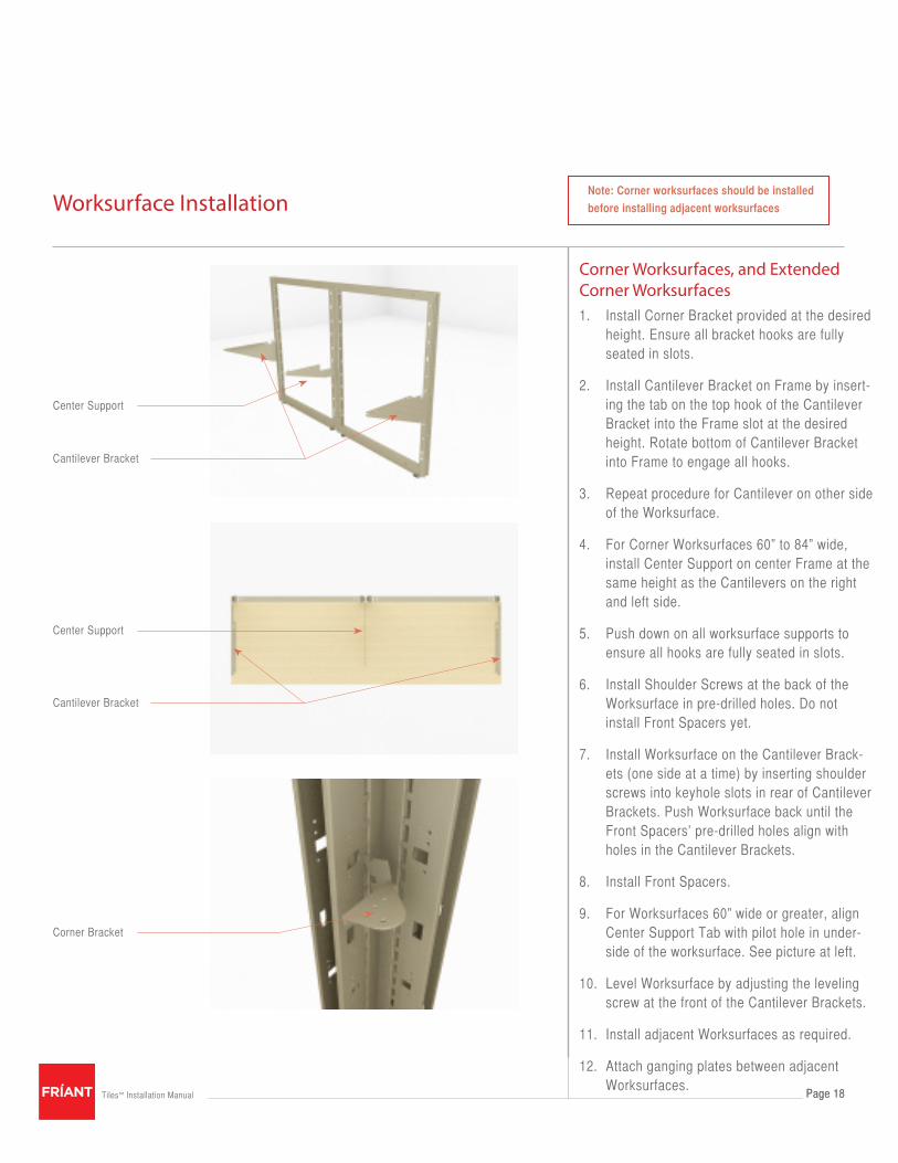
Note: Corner worksurfaces should be installed
before installing adjacent worksurfaces
Corner Worksurfaces, and Extended Corner Worksurfaces1. Install Corner Bracket provided at the desired
height. Ensure all bracket hooks are fully seated in slots.
2. Install Cantilever Bracket on Frame by insert-ing the tab on the top hook of the Cantilever Bracket into the Frame slot at the desired height. Rotate bottom of Cantilever Bracket into Frame to engage all hooks.
3. Repeat procedure for Cantilever on other side of the Worksurface.
4. For Corner Worksurfaces 60” to 84” wide, install Center Support on center Frame at the same height as the Cantilevers on the right and left side.
5. Push down on all worksurface supports to ensure all hooks are fully seated in slots.
6. Install Shoulder Screws at the back of the Worksurface in pre-drilled holes. Do not install Front Spacers yet.
7. Install Worksurface on the Cantilever Brack-ets (one side at a time) by inserting shoulder screws into keyhole slots in rear of Cantilever Brackets. Push Worksurface back until the Front Spacers’ pre-drilled holes align with holes in the Cantilever Brackets.
8. Install Front Spacers.
9. For Worksurfaces 60” wide or greater, align Center Support Tab with pilot hole in under-side of the worksurface. See picture at left.
10. Level Worksurface by adjusting the leveling screw at the front of the Cantilever Brackets.
11. Install adjacent Worksurfaces as required.
12. Attach ganging plates between adjacent Worksurfaces.

Page 19Tiles™ Installation Manual
Worksurface Installation
Page 19
1200 and 1350 Worksurface Installation
Note: 1200 and 1350 Worksurfaces should be
installed before adjacent Worksurfaces.
1. Install Corner Bracket provided in the corner at the desired height. Ensure all bracket hooks are fully seated in slots.
2. Install Cantilever Bracket on Frame by inserting the tab on the top hook of the Cantilever Bracket into the Frame slot at the desired height. Rotate bottom of Cantilever Bracket into Frame to engage all hooks.
3. Repeat procedure for Cantilever on other side of the Worksurface.
4. Install Shoulder Screws at the back of the Worksurface in pre-drilled holes. Do not install Front Spacers yet.
5. Install Worksurface on the Cantilever Brackets (one side at a time) by insert-ing shoulder screws into keyhole slots in rear of Cantilever Brackets. Push Worksurface back until the Front Spac-ers’ predrilled holes align with holes in the Cantilever Brackets.
6. Install Front Spacers.
7. Install adjacent Worksurfaces if needed.
8. Level Worksurface by adjusting the lev-eling screw at the front of the Cantilever Brackets.
9. Attach ganging plates between adjacent Worksurfaces.
Corner Bracket
Right hand Cantilever
Corner Bracket
Left hand Cantilever

Page 20Tiles™ Installation Manual
Transaction Surfaces Installation
Page 20
Corner Transaction Surface (same procedure as above)
1. Remove Top Tiles from both sides of Frames.
2. Remove existing Frame Top Cap from Frames and store for future use.
3. Secure Mounting U-shape Brackets provided to the bottom of the Transaction Surface, using pre-drilled holes.
4. Align Corner Transaction Surface on Frames and push down until firmly seated.
5. Secure Rectangular Transaction Surface Assembly to Frame, using self-drilling screws provided. Use pre-drilled holes in Brackets as template.
6. Replace Tiles on Frame.
Frame
Mounting Bracket
Self Drilling Screws
Transaction Surface
Mounting Brackets
Screws
Rectangular Transaction Surface1. Remove Top Tiles from both sides of
Frame.
2. Remove existing Frame Top Cap from Frame and store for future use.
3. Secure Mounting U-shape Brackets (pro-vided) to the bottom of the Transaction Surface, using the pre-drilled holes.
NOTE: Two (2) Mounting Brackets are re-
quired for 24” and 30”W Transaction Surface.
Three (3) Mounting Brackets are required for
36”, 42” and 48”W Transaction Surface.
Four (4) Mounting Brackets are required for
60”W Transaction Surfaces.
4. Center Rectangular Transaction Surface on Frame and push down until firmly seated.
5. Secure Rectangular Transaction Surface Assembly to Frame with self-drilling screws provided. Use pre-drilled holes in Brackets as template.
6. Replace Tiles on Frame.

Page 21Tiles™ Installation Manual
Worksurface Support End Panels, and Half Leg Installation
Page 21
End Panel and Half Leg Installation1. Position Hanger Clip to End Panel, ei-
ther in a right hand or left hand position as required.
2. Install and tighten four (4) screws into outer holes of Hanger Clip.
NOTE: Do not install safety clip at this time.
3. Mount End Panel or Half Leg with bot-tom Hanger Clip hook engaged in sec-ond slot from bottom of Frame. Hanger Clip can be mounted one slot higher or lower depending on required Worksur-face height.
NOTE: Safety Clip must be secured to End
Panel and Frame. Failure to do so could
cause product instability and/or physical
injuries.
4. Install Safety Clip into Hanger Frame and align Clip with pilot holes in Support Panel. Tighten screws to secure safety clip.
5. Level End Panel or Half Leg by adjusting Glide under front end of Support Panel.
Installing Worksurfaces
1. Mount Worksurface onto End Panel or Half Leg by inserting shoulder screw into rear slotted hole on top of End Panel or Half Leg. Push Worksurface back until Front Spacer screw drops into front hole of Support Panel.
2. For Half Legs, install Ganging Plates between adjacent Worksurfaces.
Slotted Hole
Hanger Clip
Safety Clip
Glide

Page 22Tiles™ Installation Manual
Open Metal Worksurface Support Installation
Page 22
NOTE: Open Metal Worksurface Support is
only to be used in End Run Application.
1. Assemble Bracket and Spacers as shown. Adjust for right or left hand Instal-lation.
2. Hold Bracket and Spacers together. Install Bushing and secure with Cap Screw. Do not tighten. Align Bracket Assembly in the correct position and tighten Cap Screw.
3. Adjust the height of the Bracket Assembly by removing the Adjustment Screw. Slide the inner tube to the desired height and re-insert Adjustment Screw. Tighten screw.
4. Make sure the Adjustment Screw faces under the Worksurface and is not visible from the End of Run.
5. Adjust Safety Clips and Attachment Bracket for right or left application
6. Align bottom Attachment Bracket with bottom slot in Hanger Frame. Insert At-tachment Brackets into Hanger Frame and push down on Open Metal Worksurface Support until firmly seated.
7. Insert Safety Clip into Hanger Frame. Align holes in Safety Clip with holes in Open Return, and secure Safety Clip with screws provided.
Note: Safety Clip must be secured to Open
Return and Frame. Failure to do so could cause
product instability and/or physical injuries.
8. Install Corner Worksurface Bracket to match the height of the Bracket Assembly.
9. Install Worksurface.
Attachment bracket
Safety Clips
Bracket
Spacers
Front Tube
Corner Worksurface Bracket
Bushing and Cap Screw

Page 23Tiles™ Installation Manual
Door Frame Installation
Page 23
NOTE: Door swing cannot be changed.
If opposite swing configuration is needed,
a new door is required.
1. Door Frame is factory assembled for either left or right hand swing.
2. Place Door Frame at the proper location with door swing on the desired side of Frame.
3. Connect Door Frame to adjacent Frame with Draw Rod.
4. Adjust adjacent Frame Glides so door opening is square with the door. Door Frame must be parallel to the flat face of the door.
5. Loosen bottom screws on each side of opening above Threshold. Press Thresh-old to floor and tighten screws.
6. Position Trim Strips and press in place.
Top Jam
Threshold
Threshold
Screw
Trim Strips
Page 24Tiles™ Installation Manual
Supporting Pedestals and Lateral FilesInstallation
Page 24
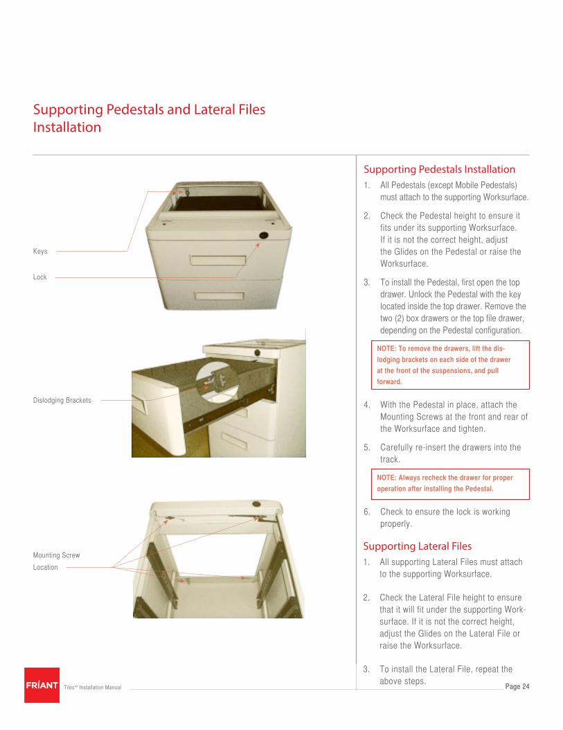
Supporting Pedestals Installation1. All Pedestals (except Mobile Pedestals)
must attach to the supporting Worksurface.
2. Check the Pedestal height to ensure it fits under its supporting Worksurface. If it is not the correct height, adjust the Glides on the Pedestal or raise the Worksurface.
3. To install the Pedestal, first open the top drawer. Unlock the Pedestal with the key located inside the top drawer. Remove the two (2) box drawers or the top file drawer, depending on the Pedestal configuration.
NOTE: To remove the drawers, lift the dis-
lodging brackets on each side of the drawer
at the front of the suspensions, and pull
forward.
4. With the Pedestal in place, attach the Mounting Screws at the front and rear of the Worksurface and tighten.
5. Carefully re-insert the drawers into the track.
NOTE: Always recheck the drawer for proper
operation after installing the Pedestal.
6. Check to ensure the lock is working properly.
Keys
Lock
Dislodging Brackets
Mounting Screw
Location
Supporting Lateral Files1. All supporting Lateral Files must attach
to the supporting Worksurface.
2. Check the Lateral File height to ensure that it will fit under the supporting Work-surface. If it is not the correct height, adjust the Glides on the Lateral File or raise the Worksurface.
3. To install the Lateral File, repeat the above steps.

5.1.10
4901 EAST 12th St / Oakland / California 94601 / T: 510.535.5113 / F: 510.535.5237 / friant.com


