Tilted axis rotation, candidates for chiral bands, and wobbling motion in 138Nd
C. M. Petrache,1 S. Frauendorf,2 M. Matsuzaki,3 R. Leguillon,1 T. Zerrouki,1 S. Lunardi,4 D. Bazzacco,4 C. A. Ur,4 E. Farnea,4
C. Rossi Alvarez,4 R. Venturelli,4 and G. de Angelis5
1Centre de Spectrometrie Nucleaire et de Spectrometrie de Masse, Universite Paris-Sud and CNRS/IN2P3,Batiment 104-108, F-91405 Orsay, France
2Department of Physics, University of Notre Dame, Notre Dame, Indiana 46556, USA3Department of Physics, Fukuoka University of Education, Munakata, Fukuoka 811-4192, Japan
4Dipartimento di Fisica dell’Universit and INFN Sezione di Padova, I-35131 Padova, Italy5INFN Laboratori Nazionali di Legnaro, I-35020 Legnaro, Italy
(Received 13 July 2012; revised manuscript received 6 September 2012; published 17 October 2012)
High-spin states in 138Nd were investigated using the reaction 94Zr(48Ca, 4n), detecting coincident γ rays withthe GASP spectrometer. A rich level scheme was constructed including four bands of negative parity at low spins,eight bands of dipole transitions, and eight bands of quadrupole transitions at medium spins. The cranked shellmodel and the tilted-axis cranking model are used to assign configurations to the observed bands, where zeropairing is assumed. For selected configurations the case of finite pairing is also considered. A consistent notationfor configuration assignment that applies for both zero and finite pairing is introduced. The observed bands areinterpreted as rotation around the short and long principal axes (quadrupole bands), as well as around a tiltedaxis (dipole bands). The dipole bands have an intermediate character, between magnetic and collective electricrotation. A pair of dipole bands is identified as candidates for chiral partners. The possible existence of thewobbling mode at low deformation and medium spins is discussed. The consistent interpretation of the multitudeof observed bands strongly supports the existence of stable triaxial deformation at medium spins in 138Nd.
The existence of triaxial nuclei has been the subject ofa longstanding debate. The possibility of soft and rigidtriaxiality has been proposed very early [1,2], and manytheoretical and experimental studies have been devoted tothis intriguing phenomenon since then. More recently, twounique fingerprints of triaxiality in nuclei have been intensivelystudied: the wobbling motion [3] and the dynamic chirality[4,5]. These exotic types of motion were observed in specificregions of the nuclear chart: the wobbling motion in theodd-even Lu nuclei with A ∼ 160 [6] and the chirality primarlyin the odd-odd and odd-even nuclei with A ∼ 130 nuclei[4,7,8]. In the nuclei 136−140Nd, surrounding the subject of thepresent paper, the rotational bands at medium and high spinshave been successfully interpreted with model calculationsbased on triaxial shapes [9–13]. In the same mass regionnearly degenerate bands with the same spin and parity havebeen observed, and interpreted as chiral partners (for example134Pr and 135Nd [4,7,8]). As a primary prerequisite of chirality,the nuclides must have a triaxial shape. The evolution fromaxial to triaxial shape in 136Nd was discussed in Ref. [9].The authors of Refs. [11–13] proposed stable triaxiality athigh-spin in 138,139,140Nd. A highly deformed band in 138Ndand a superdeformed (SD) band in 140Nd were suggested inRefs. [14,15], respectively.
The present study is devoted to 138Nd and reports states atlow and medium spins. The level scheme has been constructedup to much higher spins and excitation energy of around 45hand 24 MeV, respectively. Many new levels were establishedat low and medium spins, leading to a very rich and rathercomplete level scheme. Of particular interest are one band of
quadrupole transitions which is interpreted as manifestationof the wobbling mode and several dipole bands which areinterpreted as rotation around a tilted axis of the intrinsicreference system. Such a variety of excitations in a singlenucleus, most of them being explained by assuming a triaxialshape, makes 138Nd one of the best studied examples oftriaxiality at medium and high spins.
The level structure of 138Nd was first studied using a (p, 4n)reaction by Yoshikawa [17] and through the β+ decay of138Pm by Deslauriers et al. [18]. High-spin states in 138Ndhave been previously studied by Muller-Veggian et al. [19,20]and de Angelis et al. [21] up to spin 19h and 21h, respectively.More recently, four high-spin bands were observed in 138Ndusing the 94Zr(48Ca, 4n) reaction at an energy of 195 MeV[11]. Gamma-ray coincidences were measured with the 8π
spectrometer consisting of 20 Ge detectors with anti-Comptonshields and an inner ball of 71 BGO scintillator detectors.Two of the four observed bands were linked to low-lyingstates. A highly deformed band was also reported froma GASP experiment using the same 94Zr(48Ca, 4n) reactionat beam energies of 188 and 195 MeV [14]. The linkingtransitions of the highly deformed band to low-lying stateswere not identified, and therefore the spins and parity were notdetermined experimentally.
The details of the experimental setup are briefly discussed inSec. II. The results including the level scheme are presented inSec. III. The configurations of the different bands are discussedin Sec. IV on the basis of theoretical calculations using theCranked Shell Model (CSM) [22], the Tilted Axis Cranking(TAC) model [5,23,24], and the Cranked Nilsson + BCSformalism [25–27]. Finally, the configuration assignments anda summary are given in Secs. V and VI.
C. M. PETRACHE et al. PHYSICAL REVIEW C 86, 044321 (2012)
II. EXPERIMENTAL DETAILS
High-spin states in 138Nd have been populated via the94Zr(48Ca, 4n) reaction at beam energies of 188 and 195 MeV.The target consisted of a stack of two self-supporting 94Zrfoils of 400 μg/cm2 thickness each. The 48Ca beam of3−4 pnA was provided by the XTU Tandem accelerator ofthe Laboratori Nazionali di Legnaro. The GASP array with 40Compton-suppressed Ge detectors and the 80-element BGOball has been used for a standard coincidence measurement.Events were collected when at least three suppressed Gedetectors and three BGO detectors of the inner ball fired incoincidence. A total of 1.9 x 10⁹ triple- or higher-fold eventshave been collected. The 138Nd nucleus was one of the mostintensely populated in the reaction, with about 30% of thefusion cross section.
In order to search for discrete bands we have pro-duced a three-dimensional histogram of energies from triple-coincident γ -ray events, from which we extracted γ -γmatrices gated on selected transitions of 138Nd. From thecoincidence relationships we could assign to 138Nd manynew transitions, which are organized in several bands. Thetransition multipolarities have been extracted from the Direc-tional Correlation of Oriented states (DCO) ratios using theprocedure described in Ref. [7].
III. RESULTS AND LEVEL SCHEME
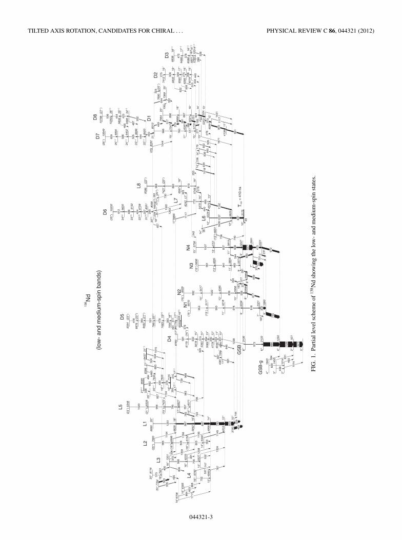
The level scheme of 138Nd is shown in Fig. 1. Most of theobserved transitions were grouped in four bands of negativeparity at low spins (N1–N4), eight bands at medium spins(L1–L8), and eight bands of dipole transitions (D1–D8). Wealso draw the levels which were assigned to the γ band fromβ-decay studies [18], even though they were not observed inthe present experiment. The energies, relative intensities, DCOratios, and spin-parity assignments of the observed transitionsare reported in Table I. The spectroscopic data on 138Nd arevery much enriched with respect to the previous studies [11,17–21]. The newly constructed level scheme will be discussedseparately for the bands of quadrupole and dipole transitions.
A. Ground-state band and the negative-parity states
The ground-state band is yrast up to spin 6+. The 69-keVtransition connecting the 10+ isomer to the 8+ state was notobserved in our measurement. Evidence for the existence ofthis transition was given in Ref. [20], where the measuredenergy was 66.9 keV. We add credibility to the 69-keVvalue, which results from the difference between the 8+ and10+ states whose energies are well established through theconnecting transitions between many high-spin states of thepresent level scheme which were not observed in Ref. [20].The only other observed transition populating the 8+ state isthe newly observed 1238-keV transition de-exciting the dipoleband D4.
Most of the populated states decay through γ cascadesinvolving the two 556.7- and 557.3-keV members of the557-keV triplet peak. We observed all the previously reportedtransitions between the negative-parity states and toward the
ground-state band and their positions in the level scheme areconfirmed, with the exception of the 563-, 839-, and 1022-keVtransitions. The 563-keV transition belongs to 138Nd butde-excites the 20+ state at 7764 keV toward which decays thestrongest high-spin rotational band, which will be publishedseparately [16]. The 839- and 1022-keV transitions are inmutual coincidence and were placed in the newly observedband N2. We observed several new transitions between thelow-lying negative-parity states with energies of 144, 187, 359,558, and 577 keV, and we inverted the order of the transitionsin the cascades 373–677 and 391–659 keV. We also changedthe parity of the two nonyrast 8+ states to negative parity. Thethree newly observed transitions with energies of 187, 558, and577 keV firmly define the new 10− state at 3556 keV, on top ofwhich are placed the 839-, 1022-, and 992-keV quadrupoletransitions of band N2. The 8− state at 2998 keV has anunbalanced intensity, with twice more intensity feeding thestate than the intensity de-exciting it. This can be an indicationof the isomeric character of the 8− state with a lifetime ofthe order of several nanoseconds, but this was not possible todeduce from the present data set.
The high-lying levels of these bands are nonyrast andtherefore are very weakly populated. The most intense are theN3 and N4 bands, which are strongly populated from the 10+state through the 329- and 454-keV transitions, respectively.We identified one more transition on top of both bands N1and N2, with energies of 953 and 992 keV, respectively. Thenew 926-keV transition populating the 11− state of band N4at 3915 keV is in cascade with the new 736-keV transitionde-exciting the 14− state lying below band D1. We have alsoidentified a new weak transition of 242 keV linking the 16−state of band D1 to the 15− state of band N4, which mostprobably is an M1/E2 transition.
An important experimental result is that we confirm theDCO for the 1018-keV transition populating the 13− state ofband N4, which is in agreement with a stretched quadrupoletransition. We assign an E2 multipolarity to the 1018-keVtransition, which therefore de-excites a 15− state and inducesa negative parity for band D1. This result and the observationof the 242-keV transition and of the 736–926 keV cascadelinking band D1 to N4 are all arguments in favor of negativeparity for band D1, which is in disagreement with Ref. [21],in which a positive-parity was proposed for band D1.
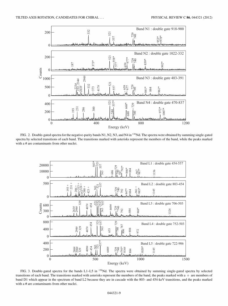
Spectra obtained by doubly gating on selected transitionsof the different bands are shown in Fig. 2.
B. The medium-spin bands L1–L5
The most intense band above the 10+ state at 3700 keV isband L1, which was assigned a πh2
11/2 configuration from thesystematics of the 10+ states in the sequence of the N = 78 iso-tones and from the comparison with the 136Ce proton core [21].In addition to band L1, we identified four more bands, labeledL2–L5, which mainly decay to band L1. Spectra showing thetransitions in the different bands are given in Fig. 3.
Some of the transitions connecting bands L2–L5 to bandL1 were observed previously [21]. Bands L3 and L4 decay toband L1 via both stretched and nonstretched E2 transitions.
044321-2
TILTED AXIS ROTATION, CANDIDATES FOR CHIRAL . . . PHYSICAL REVIEW C 86, 044321 (2012)
FIG
.1.
Part
iall
evel
sche
me
of13
8N
dsh
owin
gth
elo
w-
and
med
ium
-spi
nst
ates
.
044321-3
C. M. PETRACHE et al. PHYSICAL REVIEW C 86, 044321 (2012)
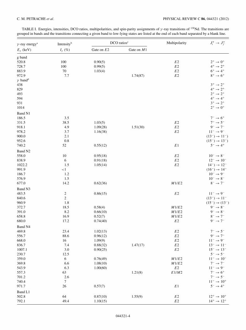
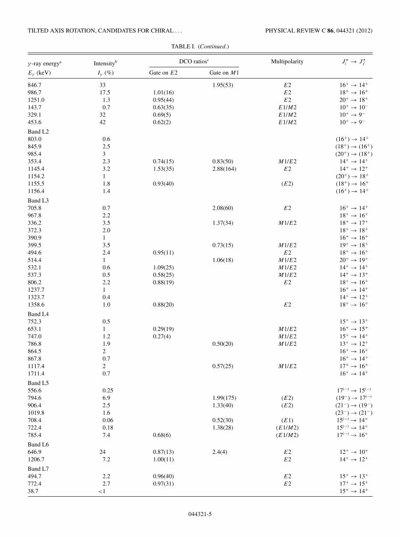
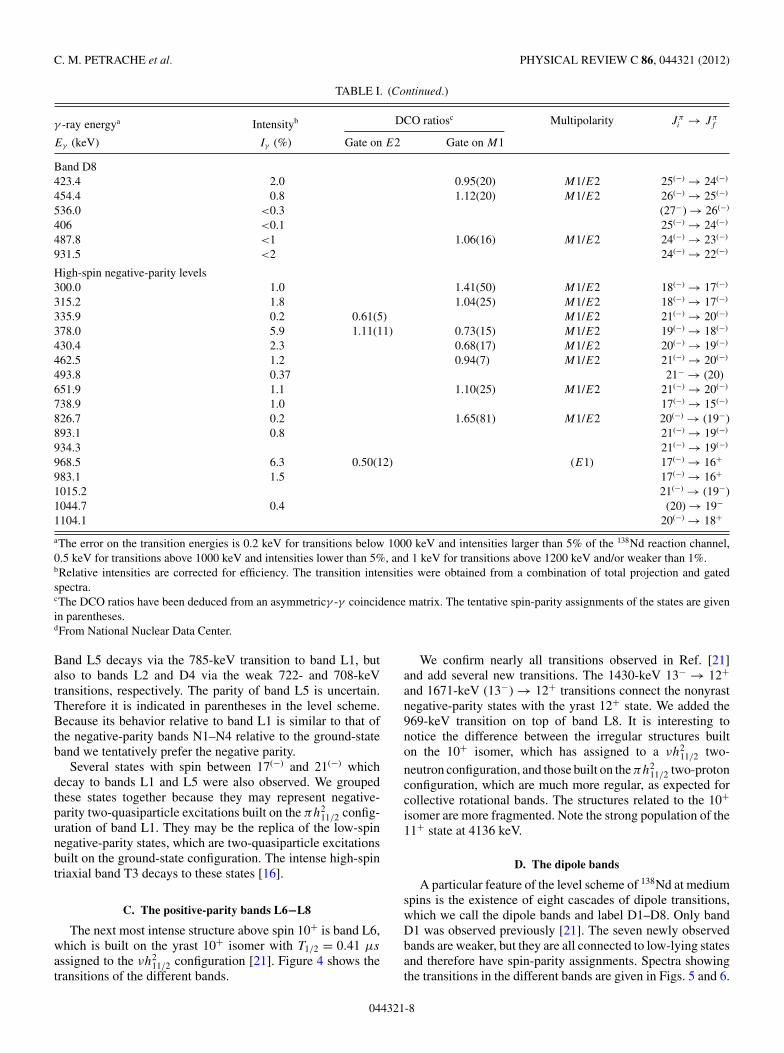
TABLE I. Energies, intensities, DCO ratios, multipolarities, and spin-parity assignments of γ -ray transitions of 138Nd. The transitions aregrouped in bands and the transitions connecting a given band to low-lying states are listed at the end of each band separated by a blank line.
aThe error on the transition energies is 0.2 keV for transitions below 1000 keV and intensities larger than 5% of the 138Nd reaction channel,0.5 keV for transitions above 1000 keV and intensities lower than 5%, and 1 keV for transitions above 1200 keV and/or weaker than 1%.bRelative intensities are corrected for efficiency. The transition intensities were obtained from a combination of total projection and gatedspectra.cThe DCO ratios have been deduced from an asymmetricγ -γ coincidence matrix. The tentative spin-parity assignments of the states are givenin parentheses.dFrom National Nuclear Data Center.
Band L5 decays via the 785-keV transition to band L1, butalso to bands L2 and D4 via the weak 722- and 708-keVtransitions, respectively. The parity of band L5 is uncertain.Therefore it is indicated in parentheses in the level scheme.Because its behavior relative to band L1 is similar to that ofthe negative-parity bands N1–N4 relative to the ground-stateband we tentatively prefer the negative parity.
Several states with spin between 17(−) and 21(−) whichdecay to bands L1 and L5 were also observed. We groupedthese states together because they may represent negative-parity two-quasiparticle excitations built on the πh2
11/2 config-uration of band L1. They may be the replica of the low-spinnegative-parity states, which are two-quasiparticle excitationsbuilt on the ground-state configuration. The intense high-spintriaxial band T3 decays to these states [16].
C. The positive-parity bands L6−L8
The next most intense structure above spin 10+ is band L6,which is built on the yrast 10+ isomer with T1/2 = 0.41 μs
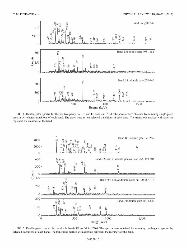
assigned to the νh211/2 configuration [21]. Figure 4 shows the
transitions of the different bands.
We confirm nearly all transitions observed in Ref. [21]and add several new transitions. The 1430-keV 13− → 12+and 1671-keV (13−) → 12+ transitions connect the nonyrastnegative-parity states with the yrast 12+ state. We added the969-keV transition on top of band L8. It is interesting tonotice the difference between the irregular structures builton the 10+ isomer, which has assigned to a νh2
11/2 two-neutron configuration, and those built on the πh2
11/2 two-protonconfiguration, which are much more regular, as expected forcollective rotational bands. The structures related to the 10+isomer are more fragmented. Note the strong population of the11+ state at 4136 keV.
D. The dipole bands
A particular feature of the level scheme of 138Nd at mediumspins is the existence of eight cascades of dipole transitions,which we call the dipole bands and label D1–D8. Only bandD1 was observed previously [21]. The seven newly observedbands are weaker, but they are all connected to low-lying statesand therefore have spin-parity assignments. Spectra showingthe transitions in the different bands are given in Figs. 5 and 6.
044321-8
TILTED AXIS ROTATION, CANDIDATES FOR CHIRAL . . . PHYSICAL REVIEW C 86, 044321 (2012)
0
200
0
200
0
500
1000
0 400 800 1200Energy (keV)
0
200
400
Band N1 : double gate 918-900
Band N2 : double gate 1022-332
Band N3 : double gate 483-391
Band N4 : double gate 470-837
668*
332
332
223#
232,
234
#26
3#
417#
286
193 23
1
294#
380
521
521
521
521
557*
972*
729
961*
1007
*
68054
4
729
729
729
841*65
9
740
740
740
740
557
884
373
558*
557
677*
839*
992*
373*
187
953*
577
659
978*
677
Cou
nts
FIG. 2. Double-gated spectra for the negative-parity bands N1, N2, N3, and N4 in 138Nd. The spectra were obtained by summing single-gatedspectra by selected transitions of each band. The transitions marked with asterisks represent the members of the band, while the peaks markedwith a # are contaminants from other nuclei.
0
10000
20000
0
500
0
300
600
Cou
nts
0
400
800
0 500 1000 1500Energy (keV)
0
200
400
Band L1 : double gate 454-557
Band L2 : double gate 803-454
Band L3 : double gate 706-503
Band L4 : double gate 752-503
Band L5 : double gate 722-906
521
521
521
521
521
557
557
557
729
729
729
729
729
884
884
884
884
884
503*
563
686
740
787 79
2*79
279
278
779
5*
846*
967
987*
1145
1145
1156
503
669#
740
740
740
740
847*
961
+
193
+23
1 +
286
+31
3 +
324
+35
3 380
+42
3 +
985*
329
407#
407#
409#
263#
294#
290#
280#
294#
454
454
454
532
537
968*
1324
329
557
557*
563
563
653
640#
972
806
816#50
3
1020
*
329
FIG. 3. Double-gated spectra for the bands L1–L5 in 138Nd. The spectra were obtained by summing single-gated spectra by selectedtransitions of each band. The transitions marked with asterisks represent the members of the band, the peaks marked with a + are members ofband D1 which appear in the spectrum of band L2 because they are in cascade with the 803- and 454-keV transitions, and the peaks markedwith a # are contaminants from other nuclei.
044321-9
C. M. PETRACHE et al. PHYSICAL REVIEW C 86, 044321 (2012)
0
5x10⁴
105
0
150
300
Cou
nts
0 500 1000 1500Energy (keV)
0
300
600Band L8: double gate 278-440
Band L7: double gate 495-1152
Band L6: gate 647
819
860
969 11
52
1207
*
639
111749
5
1609
1263
440
231,
228
286
379,
381
193
602
324
424
156
557
1263
772*
521
278
819
424
518
293
293
1117
860
488
357
647
1322
647
819*
1207
336
228
860*
969*
325
357
120 18
7
278
293
313
357
772
1431
1671
228
424
1117
FIG. 4. Double-gated spectra for the positive-parity L6, L7, and L8 bands in 138Nd. The spectra were obtained by summing single-gatedspectra by selected transitions of each band. The gates were set on selected transitions of each band. The transitions marked with asterisksrepresent the members of the band.
0
2000
4000
0
300
600
0
200
400
0 500 1000 1500Energy (keV)
0
100
200
Band D1: double gate 193-286
Band D2: sum of double gates on 268-275-349-404
Band D3: sum of double gates on 120-187-313
Band D4: double gate 201-1238
231*
313
324
380*
440
Cou
nts
518*
557
602 74
072
9
803
926
1152
444
449*
884
315*
376
290*
280
294*
233*
972
521
224
729
557 88
4
120* 18
7*
324
373 37
8*
472*
521
528
647
729
961
803
268*
275*
349* 63
964
7
1152
521
803
332
313
324
961
647
659
668
505
423
521
506*
502*
581*
1431
1117
FIG. 5. Double-gated spectra for the dipole bands D1 to D4 in 138Nd. The spectra were obtained by summing single-gated spectra byselected transitions of each band. The transitions marked with asterisks represent the members of the band.
044321-10
TILTED AXIS ROTATION, CANDIDATES FOR CHIRAL . . . PHYSICAL REVIEW C 86, 044321 (2012)
0
400
800
0
400
800
0
1000
2000
0 500 1000 1500Energy (keV)
0
150
300
450
Band D5: double gate 478-311
Cou
nts
Band D6: sum of double gates 1263-228-356-488
Band D7: double gate 286-440
Band D8: double gate 286-932
379,
381
379,
381
228*
518
518
449
44923
123
119
319
3
313
313
324,
323
324,
323
423*
440
505*44
4*
932
1152
1152
1152
1207
961
961
647
647
647
884
884
884
729
729
729
729
521*
803
803
557
557
837
819
224* 39
3*
973
581 79
2
503
557
740
294,
290
329
315
454
233
278
295
440
424*
488*
495
503
77255
7357*
325
521
394*
666#
588
659
454 53
6
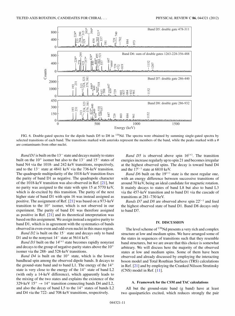
FIG. 6. Double-gated spectra for the dipole bands D5 to D8 in 138Nd. The spectra were obtained by summing single-gated spectra byselected transitions of each band. The transitions marked with asterisks represent the members of the band, while the peaks marked with a #are contaminants from other nuclei.
Band D1 is built on the 13− state and decays mainly to statesbuilt on the 10+ isomer but also to the 13− and 15− states ofband N4 via the 1018- and 242-keV transitions, respectively,and to the 13− state at 4841 keV via the 736-keV transition.The quadrupole multipolarity of the 1018-keV transition fixesthe parity of band D1 as negative. The quadrupole characterof the 1018-keV transition was also observed in Ref. [21], butno parity was assigned to the state with spin 15 at 5770 keV,which is de-excited by this transition. The parity of the nexthigher state of band D1 with spin 16 was instead assigned aspositive. The assignment of Ref. [21] was based on a 973-keVtransition to the 10+ isomer, which is not observed in ourexperiment. The parity of band D1 was therefore assignedas positive in Ref. [21] and its theoretical interpretation wasbased on this assignment. We assign instead a negative parity toband D1, which is in agreement with the systematics of bandsobserved in even-even and odd-even nuclei in this mass region.
Band D2 is built on the 15− state and decays only to bandD1 and to the nonyrast 14− state at 5614 keV.
Band D3 built on the 14(+) state becomes rapidly nonyrastand decays to the group of negative-parity states above the 10+isomer via the 288- and 528-keV transitions.
Band D4 is built on the 10+ state, which is the lowestbandhead spin among the observed dipole bands. It decays tothe ground-state band and to band L1. The energy of the 14+state is very close to the energy of the 14+ state of band L2(with only a 14-keV difference), which apparently leads tothe mixing of the two states and explains the existence of the329-keV 15+ → 14+ transition connecting bands D4 and L2,and also the decay of band L5 to the 14+ states of bands L2and D4 via the 722- and 708-keV transitions, respectively.
Band D5 is observed above spin 16(+). The transitionenergies increase regularly up to spin 21 and becomes irregularat the highest observed spins. The decay is toward band D4and the 17(−) state at 6810 keV.
Band D6 built on the 19(+) state is the most regular one,with an energy difference between successive transitions ofaround 70 keV, being an ideal candidate for magnetic rotation.It mainly decays to states of band L8 but also to band L3via the 457-keV transition and to band D1 via the cascade oftransitions at 281–730 keV.
Bands D7 and D8 are observed above spin 22(−) and feedthe highest observed state of band D1. Band D8 decays onlyto band D7.
IV. DISCUSSION
The level scheme of 138Nd presents a very rich and complexstructure at low and medium spins. We have arranged some ofthe states in sequences of transitions such that they resembleband structures, but we are aware that this choice is somewhatarbitrary. We will discuss here the majority of the observedstates at low and medium spins. Some of them have beenobserved and already discussed by employing the interactingboson model and Total Routhian Surfaces (TRS) calculationsin Ref. [21] and by employing the Cranked Nilsson Strutinsky(CNS) model in Ref. [11].
A. Framework for the CSM and TAC calculations
All but the ground-state band (g band) have at leasttwo quasiparticles excited, which reduces strongly the pair
044321-11
C. M. PETRACHE et al. PHYSICAL REVIEW C 86, 044321 (2012)
0.342
42.5
43
43.5
44
44.5
45
45.5
0 0.05 0.1 0.15 0.2 0.25 0.3 0.3h / MeV
0 100 110 120 130 140 150 160 170 18 (deg)
A B
C
A
E F
G H
I
= 90o = 0.35 MeV = 0, 180o
(MeV)0.3 0.25 0.2 0.15 0.1 0.05 0
(MeV)
e'
(MeV)
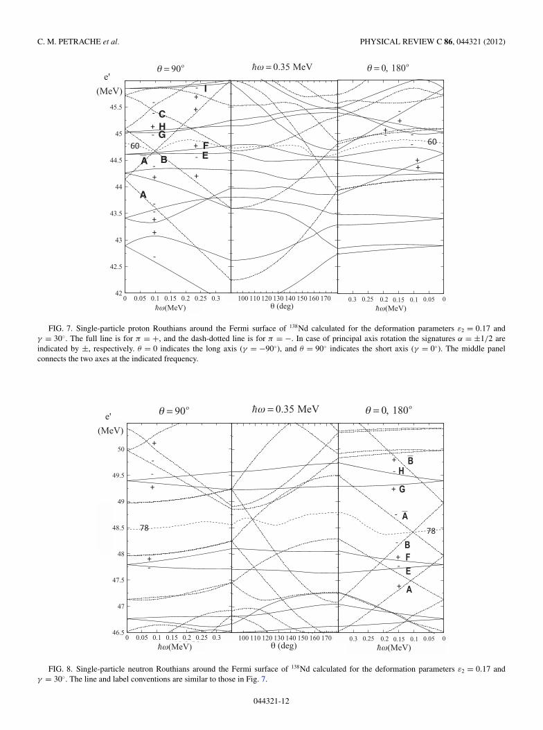
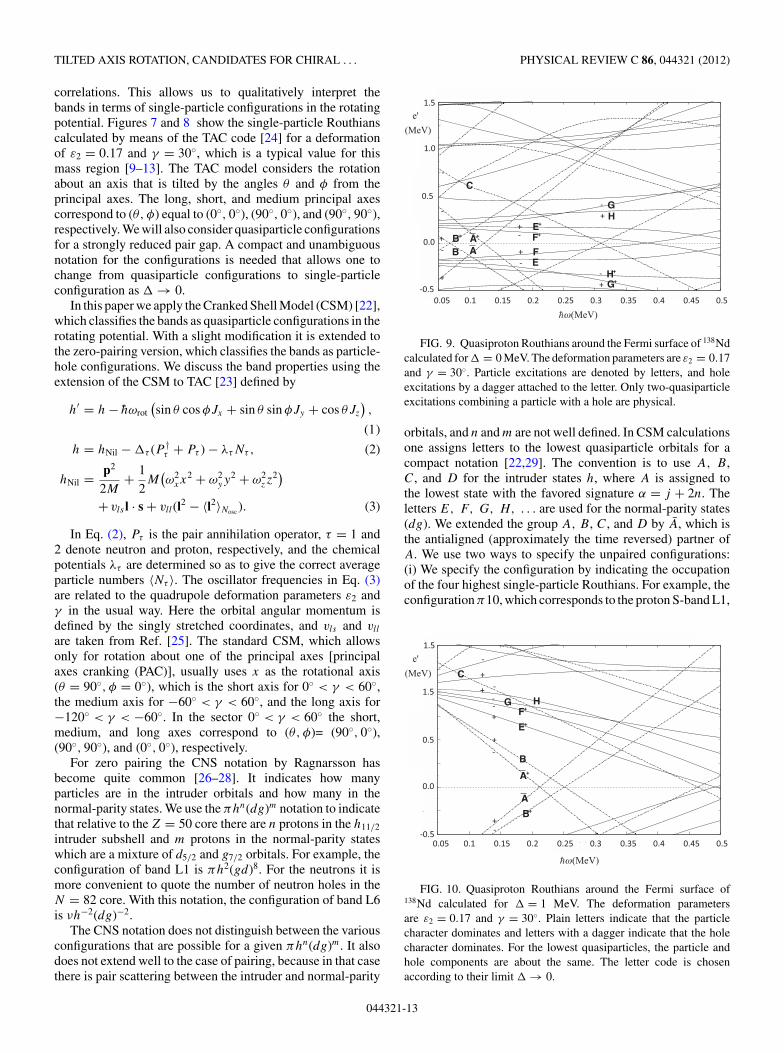
FIG. 7. Single-particle proton Routhians around the Fermi surface of 138Nd calculated for the deformation parameters ε2 = 0.17 andγ = 30◦. The full line is for π = +, and the dash-dotted line is for π = −. In case of principal axis rotation the signatures α = ±1/2 areindicated by ±, respectively. θ = 0 indicates the long axis (γ = −90◦), and θ = 90◦ indicates the short axis (γ = 0◦). The middle panelconnects the two axes at the indicated frequency.
00.050.10.150.20.250.30.35h / MeV
= 90o = 0.35 MeV = 0, 180o
46.5
47
47.5
48
5
49
49.5
50
50.5
0 0.05 0.1 0.15 0.2 0.25 0.3 0.35h / MeV
e(
)/M
eV
0 100 110 120 130 140 150 160 170 180 (deg)
A
B
A
EF
G
H
(MeV)0.3 0.25 0.2 0.15 0.1 0.05 0
(MeV)
e'
(MeV)
B
48.
FIG. 8. Single-particle neutron Routhians around the Fermi surface of 138Nd calculated for the deformation parameters ε2 = 0.17 andγ = 30◦. The line and label conventions are similar to those in Fig. 7.
044321-12
TILTED AXIS ROTATION, CANDIDATES FOR CHIRAL . . . PHYSICAL REVIEW C 86, 044321 (2012)
correlations. This allows us to qualitatively interpret thebands in terms of single-particle configurations in the rotatingpotential. Figures 7 and 8 show the single-particle Routhianscalculated by means of the TAC code [24] for a deformationof ε2 = 0.17 and γ = 30◦, which is a typical value for thismass region [9–13]. The TAC model considers the rotationabout an axis that is tilted by the angles θ and φ from theprincipal axes. The long, short, and medium principal axescorrespond to (θ, φ) equal to (0◦, 0◦), (90◦, 0◦), and (90◦, 90◦),respectively. We will also consider quasiparticle configurationsfor a strongly reduced pair gap. A compact and unambiguousnotation for the configurations is needed that allows one tochange from quasiparticle configurations to single-particleconfiguration as → 0.
In this paper we apply the Cranked Shell Model (CSM) [22],which classifies the bands as quasiparticle configurations in therotating potential. With a slight modification it is extended tothe zero-pairing version, which classifies the bands as particle-hole configurations. We discuss the band properties using theextension of the CSM to TAC [23] defined by
h′ = h − hωrot(sin θ cos φJx + sin θ sin φJy + cos θJz
),
(1)
h = hNil − τ (P †τ + Pτ ) − λτNτ , (2)
hNil = p2
2M+ 1
2M
(ω2
xx2 + ω2
yy2 + ω2
zz2)
+ vls l · s + vll(l2 − 〈l2〉Nosc ). (3)
In Eq. (2), Pτ is the pair annihilation operator, τ = 1 and2 denote neutron and proton, respectively, and the chemicalpotentials λτ are determined so as to give the correct averageparticle numbers 〈Nτ 〉. The oscillator frequencies in Eq. (3)are related to the quadrupole deformation parameters ε2 andγ in the usual way. Here the orbital angular momentum isdefined by the singly stretched coordinates, and vls and vll
are taken from Ref. [25]. The standard CSM, which allowsonly for rotation about one of the principal axes [principalaxes cranking (PAC)], usually uses x as the rotational axis(θ = 90◦, φ = 0◦), which is the short axis for 0◦ < γ < 60◦,the medium axis for −60◦ < γ < 60◦, and the long axis for−120◦ < γ < −60◦. In the sector 0◦ < γ < 60◦ the short,medium, and long axes correspond to (θ, φ)= (90◦, 0◦),(90◦, 90◦), and (0◦, 0◦), respectively.
For zero pairing the CNS notation by Ragnarsson hasbecome quite common [26–28]. It indicates how manyparticles are in the intruder orbitals and how many in thenormal-parity states. We use the πhn(dg)m notation to indicatethat relative to the Z = 50 core there are n protons in the h11/2
intruder subshell and m protons in the normal-parity stateswhich are a mixture of d5/2 and g7/2 orbitals. For example, theconfiguration of band L1 is πh2(gd)8. For the neutrons it ismore convenient to quote the number of neutron holes in theN = 82 core. With this notation, the configuration of band L6is νh−2(dg)−2.
The CNS notation does not distinguish between the variousconfigurations that are possible for a given πhn(dg)m. It alsodoes not extend well to the case of pairing, because in that casethere is pair scattering between the intruder and normal-parity
FIG. 9. Quasiproton Routhians around the Fermi surface of 138Ndcalculated for = 0 MeV. The deformation parameters are ε2 = 0.17and γ = 30◦. Particle excitations are denoted by letters, and holeexcitations by a dagger attached to the letter. Only two-quasiparticleexcitations combining a particle with a hole are physical.
orbitals, and n and m are not well defined. In CSM calculationsone assigns letters to the lowest quasiparticle orbitals for acompact notation [22,29]. The convention is to use A, B,C, and D for the intruder states h, where A is assigned tothe lowest state with the favored signature α = j + 2n. Theletters E, F, G, H, . . . are used for the normal-parity states(dg). We extended the group A, B, C, and D by A, which isthe antialigned (approximately the time reversed) partner ofA. We use two ways to specify the unpaired configurations:(i) We specify the configuration by indicating the occupationof the four highest single-particle Routhians. For example, theconfiguration π10, which corresponds to the proton S-band L1,
FIG. 10. Quasiproton Routhians around the Fermi surface of138Nd calculated for = 1 MeV. The deformation parametersare ε2 = 0.17 and γ = 30◦. Plain letters indicate that the particlecharacter dominates and letters with a dagger indicate that the holecharacter dominates. For the lowest quasiparticles, the particle andhole components are about the same. The letter code is chosenaccording to their limit → 0.
044321-13
C. M. PETRACHE et al. PHYSICAL REVIEW C 86, 044321 (2012)
is πABEF . (ii) We specify the configuration by indicatingthe particle-hole excitations relative to the S configurationπ10, which we use as reference (particle-hole vacuum). Forexample, the πABCE configuration is generated by excitingF to C, and therefore we will denote it by πF−1C.
The particle-hole notation naturally extends to the case of fi-nite pairing. In the limit → 0 a quasiparticle becomes eithera particle or a hole. There are twice as many quasiparticle statesas single-particle states. Each state has a conjugate partnerwith opposite energy, which is labeled by a dagger; e.g., A†
is the conjugate of A. Conventionally, the Routhians that havenegative energy for ω = 0 are labeled by the dagger. However,it is completely open which state of the conjugate pair is giventhe dagger. Here we use the freedom to additionally indicatewhether the quasiparticle is predominantly a particle (nodagger) or a hole (dagger). We indicate this by using the plainletters for quasiparticles that become particles and attach thedagger to the quasiparticles that become holes. For example thequasiparticle G becomes the particle G and the quasiparticleF † becomes the hole F−1. The quasiparticle vacuum is takenas the paired proton S band. The quasiparticle configurationπF †G becomes πF−1G for zero pairing. For moderate pairingthe notation still indicates that F † is predominantly a hole andG predominantly a particle. Of course, for strong pairing thelowest quasiparticles are approximately half particle and halfhole. Figures 9 and 10 illustrate the notation.
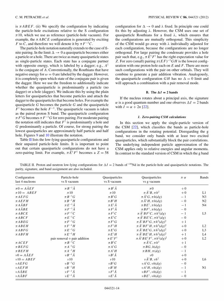
Table II lists the low-lying quasiparticle configurations andtheir unpaired particle-hole limits. It is important to pointout that certain quasiparticle configurations do not have azero-pairing limit. For example, πE†F † becomes a Z = 58
configuration for → 0 and λ fixed. In principle one couldfix this by adjusting λ. However, the CSM uses one set ofquasiparticle Routhians for a fixed λ, which ensures thatthe configurations are mutually orthogonal. This simplicityof the CSM would go away with λ individually adjusted foreach configuration, because the configurations are no longerorthogonal. For large pairing the condensate provides a holepair such that, e.g., πE†F † has the right expectation value forZ. For zero (small) pairing π (EF )−1GH is the lowest config-uration with one proton hole each on E and F . There are moresuch configurations with the pair on other orbitals. They willcombine to generate a pair addition vibration. Analogously,the quasiparticle configuration GH has no = 0 limit andwill approach a combination with a pair removal mode.
B. The �I = 2 bands
If the nucleus rotates about a principal axis, the signatureα is a good quantum number and one observes I = 2 bandswith I = α + 2n [22].
1. Zero-pairing CSM calculations
In this section we apply the single-particle version ofthe CSM [22], which classifies the bands as particle-holeconfigurations in the rotating potential. Disregarding the gband, we consider only bands with at least two excitedquasiparticles, which substantially block the pair correlations.The underlying independent particle approximation of theCSM applies only to relative energies and angular momenta.In contrast to the standard version of CSM in which the g band
TABLE II. Proton and neutron low-lying configurations for I = 2 bands of 138Nd in the particle-hole and quasiparticle notations. Theparity, signature, and band assignment are also included.
Configuration Particle-hole Quasiparticles Quasiparticles π α Bandslast 4 nucleons vs S vacuum vs S vacuum vs g vacuum
TILTED AXIS ROTATION, CANDIDATES FOR CHIRAL . . . PHYSICAL REVIEW C 86, 044321 (2012)
0 0.2 0.4 0. 6
0
0.5
1
1.5
e′ (
MeV
)
N2N3N4L2L3L4L5L1
0 0.2 0.4 0. 6
-4
0
4N2N3N4L2L3L4L5L1
0 0.2 0.4 0. 6h_ ω (MeV) h
_ ω (MeV)
0
1
e′ (
MeV
)
π B-1H (N2)
π B-1G (N3)
π E-1A- (N4)
π F-1A-
π F-1G
π F-1H (L2)
π E-1G (L3)
π E-1H (L4)
π F-1C (L5)
π E-1C
π ABEF (L1)
0 0.2 0.4 0. 6
-4
0
4
i (h_
)i (
h_)
π B-1H (N2)
π B-1G (N3)
π E-1A- (N4)
π F-1A-
π F-1G
π F-1H (L2)
π E-1G (L3)
π E-1H (L4)
π F-1C (L5)
π E-1C
π ABEF (L1)
FIG. 11. (Color online) Experimental and calculated Routhians and single-particle alignments relative to band L1 for the I = 2 bandsL2–L5 and N2–N4 of 138Nd. Parity and signature (π, α) are indicated by the line type: full (+, 0), dashed (+, 1), dotted (−, 0), and dash-dotted(−, 1).
is used as reference, in this paper we will use the proton S-bandL1 as reference.
The experimental particle-hole Routhians e′ and alignmentsi for each band are obtained by following the standardprocedure as described, e.g., in Refs. [22,23] for extractingtotal Routhians E′(I ), angular momenta J (I ), and frequenciesω(I ) from the level energies E(I ), where the expressionfor K = 0 are used. The reference functions E′
L1(ω) andJL1(ω) are constructed as smooth interpolations between thepoints E′(ω(I )) and J (ω(I )) obtained for band L1. From theEn
′(ω(I )) and Jn(ω(I )) values of a given band n we subtractthe EL1
′(ω) and JL1(ω) values of band L1 calculated at thesame frequencies,
e′n(ω(I )) = En
′(ω(I )) − EL1′(ω(I )), (4)
in(ω(I )) = Jn(ω(I )) − JL1(ω(I )). (5)
The experimental Routhians e′ and the single-particle align-ments i relative to the L1 reference are shown in the upperpanels of Figs. 11 and 20 and 21 for the bands of quadrupoleand dipole transitions, respectively. The reference band L1appears as a horizontal line in all figures.
The main features of rotational spectra can be understood ina simple way that has been discussed before (cf., e.g., [5,23]).
There are two h11/2 protons which align their angular momentawith the short axis, because this orientation corresponds tomaximal overlap of their doughnut-like density distributionwith the triaxial core. As a consequence, the h11/2 protonsfavor rotation about the short axis. As seen in the middle panelof Fig. 7, the Routhians A and B have a pronounced minimumat θ = 90◦. There are two h11/2 neutron holes, which align theirangular momenta with the long axis, because this orientationminimizes the overlap with the triaxial core. As a consequence,the h11/2 neutron holes favor rotation about the long axis. Asseen in the middle panel of Fig. 8, the neutron Routhians A andB have pronounced maxima at θ = 0◦, which means that holesin these two orbitals drive the rotational axis to θ = 0◦. Alter-natively, one may say that the two neutrons on A and B favorthe long axis. The h11/2 neutrons on the lower orbitals do notdrive the rotational axis significantly, because to each Routhiancorresponds a conjugate one (barred) that nearly compensatesfor the drive. The collective angular momentum originatingfrom the rest of the nucleons is maximal for the medium axis,for which the deviation from axial symmetry is maximal.
The TAC calculations show (see below) that the proton con-figurations with at least one of the h11/2 orbitals A, B, and C oc-cupied combined with the neutrons in the ground configurationν0 = νAAEF all rotate about the short axis (90◦, 0◦). Table II
044321-15
C. M. PETRACHE et al. PHYSICAL REVIEW C 86, 044321 (2012)
list the low-lying proton configurations, which combined withthe neutron g configuration ν0 generate the regular I = 2bands. The possible assignments to the observed bands ofquadrupole transitions in 138Nd are included as well.
The lower panels of Fig. 11 display the calculated Routhi-ans and single-particle alignments relative to the proton Sconfiguration π10 = πABEF combined with the neutrong configuration ν0, which is associated with band L1. Wecalculated the total Routhian E′(ω, θ, φ, ε, γ ) as given bythe TAC model [24] as a function of the two tilt angles θ ,φ, the deformation parameter ε, and the triaxiality parameterγ . The calculation shows that the minimum lies always at(θ, φ) = (90◦, 0◦); i.e., the nucleus rotates about the short axis.The minimum of E′ (equilibrium deformation) at a frequencyof hω = 0.3 MeV is found for ε2 = 0.15 and γ = 30◦. Wecalculated moment of inertia with these parameters. The valueof J (2) = 17.5h2/MeV compares well with the experimentalvalue of 19h2/MeV [obtained as the slope of a straight-linefit to the function JL1(ω)]. The negative-parity bands N2, N3,and N4 contain only one rotational aligned h11/2 orbital ascompared to the reference proton S configuration containingtwo of them. The panel with experimental single-particlealignments in Fig. 11 shows in fact two groups, one belowand one above the zero line corresponding to the L1 reference:the group below is formed by the bands N2–N4, which involveone h11/2 orbital, and the group above is formed by the bandsL2–L5, which involve two or three aligned h11/2 orbitals.The concrete configuration assignment is based on parity,signature, and alignment. Additionally, we took into accountthat the two bands in 136Nd that correspond to N2 and N3show a backbend [9]. The backbends are interpreted as the re-spective configuration changes πB−1G → π (EF )−1CG andπB−1H → π (EF )−1CH , which are assisted by the residualpair correlations. The alternative configurations πE−1A andπF−1A do not allow such backbends. For this reason, the N2and N3 bands are assigned to the higher pair of configurationsπB−1H and πB−1G shown in Fig. 11. (The wrong energyorder should not be of too much concern, because the neglectedcorrelations may lead to comparable energy shifts.) Excitingone or two protons from (E,F ) into (G,H ) generates thepositive-parity configurations with nearly the same alignment,slightly above the reference, which are assigned to the bandsL2, L3, and L4. Band L5 has a higher alignment than L1, whichindicates an extra h11/2 proton. For this reason we interpretit as πF−1C. All the bands associated with configurationsinvolving only protons display a regular rotational sequencewith a value of J (2) similar to that of the reference L1.
For the neutron S configuration ν10 with the two h11/2
orbitals A and B occupied, combined with the proton inthe g configuration π0 we calculated the total RouthianE′(ω, θ, φ, ε, γ ) by means of the TAC model [24]. Theminimum lies always at (θ, φ) = (0◦, 0◦); i.e., the nucleusrotates about the long axis. The equilibrium deformationfor hω = 0.4 MeV is found at ε2 = 0.14 and γ = 38◦. Thecalculated moment of inertia of J (2) = 6.5 h2/MeV is toosmall to support an extended regular rotational sequence,which reflects the proximity of the N = 82 shell closure andthe suppression of the proton angular momentum by the paircorrelations. We assign the three states of band L6 to this
configuration, which is used as reference for configurationsthat rotate about the long axis. The reference functions E′
L6(ω)and JL6(ω) are generated analogous to the reference forrotation about the short axis, by replacing L6 for L1. Thestraight-line fit to JL6 has a slope of J (2) = 8h2/MeV, whichcompares well with the TAC value. Because of the smallcollectivity of rotation about the long axis, other configurationsare not expected to support extended regular rotational bands;rather they may show up as sequences with roughly constanttransition energies (tidal waves; cf. [30]). The sequences N1,L7, and L8 are of this kind. They may correspond to theconfigurations indicated in Table II. The other configurationswith the correct parity and signature are alternatives. Anunambiguous assignment is not possible. The configurationsin Table II generated by the excitation of neutrons from the(E,F ) into the (G,H ) orbitals require around 2 MeV, whichis too high (see in Fig. 8) to qualify for bands L7 and L8.Possible alternative configurations for bands L7 and L8 caninvolve the excitation of one or two protons from (E,F ) into(G,H, I ) coupled to the neutron S configuration, as in thecase of band L2, which involves one- or two-proton excitationcoupled to the proton S configuration. Such configurations willbe considered in Sec. IV B2. However, it also seems possiblethat band L7 is the one-phonon wobbling excitation built on theneutron S configuration, which will be discussed in Sec. IV B3.
Figure 11 shows that the unpaired calculations fairly wellreproduce the relative alignments of the different bands,which were used to make the configuration assignments.The experimental alignments are shifted upward by about2h. Such a shift can be attributed to residual dynamic paircorrelations, which reduce the angular momentum of theproton S-band L1 (reference) more strongly than in theother bands (cf. Sec. IV B2). This kind of modification hasbeen discussed in Ref. [31]. The calculated Routhians crossaround hω = 0.2 MeV while with the experimental ones theycross around 0.45 MeV. Again, this is to be attributed tothe neglected correlations in our extremely simplifying CSMinterpretation. In particular, dynamic pair correlations, but alsoshape polarization, may be responsible for the energy shifts.As will be demonstrated in a forthcoming publication, onemay derive experimental single-particle Routhians from theneighboring odd-Z isotones, which place the crossing at theright frequency [32].
One should note that bands with even spin and negativeparity such as band N2 were also observed in neighboringnuclei such as 136Nd [33] and 136Ce [34], being interpreted asproton π (dg)1h1 and ν(sd)1h1, respectively. The more collec-tive behavior of the bands in 136Nd allowed their observationup to high spins after two band crossings, whereas the bands in136Ce are very similar to those observed in 138Nd. They wereinterpreted as rotational bands of a nucleus with nearly axialshape around a principal axis of the intrinsic reference system.We adopt the two-proton πB−1H configuration for band N2,which is similar to that assigned to the low-lying even-spinnegative-parity band of 136Nd.
Band N4 mainly decays to the ground-state band, andit has weak connecting transitions to the other negative-parity bands. It is interpreted as the πE−1A configuration.This interpretation is in agreement with the feeding and
044321-16
TILTED AXIS ROTATION, CANDIDATES FOR CHIRAL . . . PHYSICAL REVIEW C 86, 044321 (2012)
depopulation pattern of the band, which is mainly fed at the 9−state from band L1 through the strong 454-keV E1 transition.This can be explained by a simple quasiproton excitation fromthe π (dg) orbitals active in band N4 to the πh orbital activein band L1. The E1 transitions from band N4 to the g band,whose states are dominated by the π (dg) configuration, canalso be explained by a de-excitation from the πh orbital activein band N4 to the π (dg) orbitals active in the g band. Anotherfeature supporting the interpretation of band N4 as based onthe πE−1A configuration is that band D1, which is assignedto the πF−1A ⊗ ν10 configuration (see below), decays onlyto the 13− and 15− states of band N4 and not to the othernegative-parity bands. Furthermore, the two 9− states of bandsN1 and N4 have energies of 3239 and 3247 keV, respectively.Despite the very small energy difference of only 8 keV thetwo states do not interact. This supports the assignment ofvery different configurations to bands N1 and N4, with bandN1 built on the νB−1H configuration and band N4 built on theπE−1A configuration.
The 8− state at 2980 keV is weakly populated by the 577-and 391-keV transitions from bands N2 and N3, respectively.This can be explained by a πF−1A proton configuration andwould complete the set of four two-quasiparticle negative-parity bands based on proton configurations with even and oddspins, as also predicted by the calculations shown in Fig. 11.
The assignment of the πh2 configuration (π10) to bandL1 is also based on systematics and interacting boson modelcalculations [21]. As one can see in Figs. 12 and 13, whichshow the experimental excitation energy relative to a rotatingliquid drop reference [36], the average slope of band L1 issmaller than that of the g band, suggesting a larger moment ofinertia for band L1. This is in agreement with the results of the
0 5 10 15 20 25Spin, I [h-]
-3
-2
-1
0
1
2
E - E
rld(d
ef) (
MeV
)
Band GSB Band N1Band N2
Band N3
Band N4Band L1Band L5
FIG. 12. (Color online) Experimental excitation energy relativeto a rotating liquid drop reference for the negative-parity bands, theground-state band, and the L1 band in 138Nd. Solid and dashed linesare used for positive- and negative-parity configurations, respectively.Closed symbols are used for signature α = 0 and open symbols forsignature α = 1.
0 5 10 15 20 25Spin, I [h-]
-3
-2
-1
0
1
2
E - E
rld(d
ef) (
MeV
)
Band GSBBand GSB-gBand L1Band L2 Band L3 Band L4 Band L6Band L7Band L8
FIG. 13. (Color online) The same as in Fig. 12 for the low- andmedium-spin positive-parity bands.
TRS calculations, which show a triaxial shape with ε2 = 0.17and γ = +30◦ for the assigned πh2 configuration [21].
2. Paired CSM calculations
The CSM calculations in the preceding sections, in whichzero pairing was assumed, provide an understanding of theglobal features of the band structure. As discussed there,some deviations from the observed data remain. Here theI = 2 positive-parity bands are compared with quasiparticleconfigurations calculated by means of the CSM with finitepairing [22,35], in order to assert the consequences of residualpair correlations.
For the bands L1–L5 we repeated the calculations, adoptingthe same deformation parameters ε2 = 0.17 and γ = +30◦
-0.5
0
0.5
1
1.5
0 0.1 0.2 0.3 0.4 0.5
e′ (
MeV
)
h rot (MeV)-
E++
F+- H +
G -
C -
EEA B+
FIG. 14. Proton Routhians as functions of rotational frequencyfor 138Nd, calculated using the constant mean-field parametersε2 = 0.17, γ = +30◦, and p = 0.3 MeV. The chemical potential isadjusted at each rotational frequency so that the quasiparticle vacuumhas the correct particle number. This causes a small irregularity at thecrossing at hωrot = 0.12 MeV. Positive- and negative-parity states aredrawn by solid and dot-dashed curves, respectively.
044321-17
C. M. PETRACHE et al. PHYSICAL REVIEW C 86, 044321 (2012)
0
0.2
0.4
0.6
0.8
1
0.3 0.35 0.4 0.45 0.5
e′L
n (
MeV
)
hω rot (MeV)-
(a)
L2L3L4L5
0
0.2
0.4
0.6
0.8
1
0.3 0.35 0.4 0.45 0.5
e′ (
MeV
)
hω rot (MeV)-
(b)
πE+
F+
πF+
H
πE+
H
πF+
C
0
0.2
0.4
0.6
0.8
1
0.3 0.35 0.4 0.45 0.5
e′ (
MeV
)
hω rot (MeV)-
(c)
ν (-1/2,-1/2)ν (+1/2,+1/2)
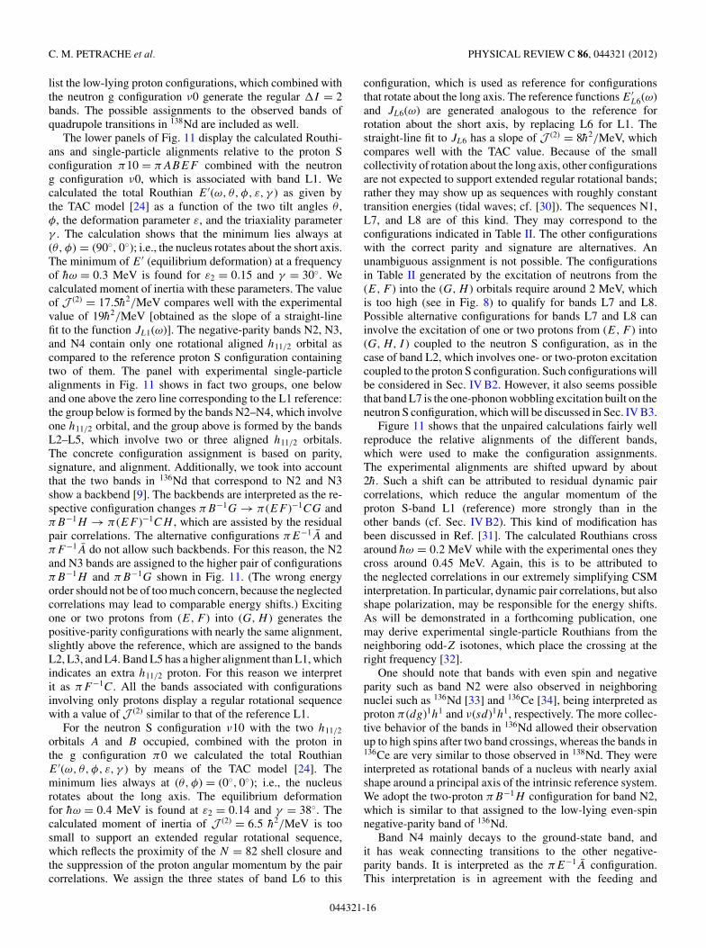
FIG. 15. (Color online) (a) Experimental Routhians of bands L2–L5 relative to that of band L1. (b) and (c) Energy difference betweenthe different calculated (two-quasiparticle ⊗ π10) configurations andthe π10 configuration assigned to band L1. The calculations areperformed at constant mean-field parameters ε2 = 0.17, γ = +30◦,and p = 0.3 MeV.
(short axis) and pairing parameters n = 1.0 MeV and p =0.3 MeV, whereas chemical potentials were adjusted at eachrotational frequency such that the quasiparticle vacuum hasthe correct particle number. As seen in Fig. 14, the protonS configuration πh2π0ν0 = π10ν0 becomes yrast at hωrot =0.12 MeV. As for the zero-pairing calculations, we examinetwo-quasiparticle excitations relative to this configuration.Figure 15(a), extracted from Fig. 11, shows the experimentalRouthians e′ of bands L2–L5 relative to band L1. Their slopes
-0.5
0
0.5
1
1.5
0 0.1 0.2 0.3 0.4 0.5
e’ (M
eV)
hωrot (MeV)-
F++
G -
I -
A -
B +
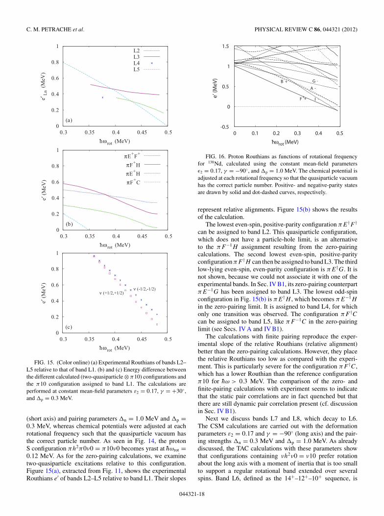
FIG. 16. Proton Routhians as functions of rotational frequencyfor 138Nd, calculated using the constant mean-field parametersε2 = 0.17, γ = −90◦, and p = 1.0 MeV. The chemical potential isadjusted at each rotational frequency so that the quasiparticle vacuumhas the correct particle number. Positive- and negative-parity statesare drawn by solid and dot-dashed curves, respectively.
represent relative alignments. Figure 15(b) shows the resultsof the calculation.
The lowest even-spin, positive-parity configuration πE†F †
can be assigned to band L2. This quasiparticle configuration,which does not have a particle-hole limit, is an alternativeto the πF−1H assignment resulting from the zero-pairingcalculations. The second lowest even-spin, positive-parityconfiguration πF †H can then be assigned to band L3. The thirdlow-lying even-spin, even-parity configuration is πE†G. It isnot shown, because we could not associate it with one of theexperimental bands. In Sec. IV B1, its zero-pairing counterpartπE−1G has been assigned to band L3. The lowest odd-spinconfiguration in Fig. 15(b) is πE†H , which becomes πE−1H
in the zero-pairing limit. It is assigned to band L4, for whichonly one transition was observed. The configuration πF †Ccan be assigned to band L5, like πF−1C in the zero-pairinglimit (see Secs. IV A and IV B1).
The calculations with finite pairing reproduce the exper-imental slope of the relative Routhians (relative alignment)better than the zero-pairing calculations. However, they placethe relative Routhians too low as compared with the experi-ment. This is particularly severe for the configuration πF †C,which has a lower Routhian than the reference configurationπ10 for hω > 0.3 MeV. The comparison of the zero- andfinite-pairing calculations with experiment seems to indicatethat the static pair correlations are in fact quenched but thatthere are still dynamic pair correlation present (cf. discussionin Sec. IV B1).
Next we discuss bands L7 and L8, which decay to L6.The CSM calculations are carried out with the deformationparameters ε2 = 0.17 and γ = −90◦ (long axis) and the pair-ing strengths n = 0.3 MeV and p = 1.0 MeV. As alreadydiscussed, the TAC calculations with these parameters showthat configurations containing νh2ν0 = ν10 prefer rotationabout the long axis with a moment of inertia that is too smallto support a regular rotational band extended over severalspins. Band L6, defined as the 14+–12+–10+ sequence, is
044321-18
TILTED AXIS ROTATION, CANDIDATES FOR CHIRAL . . . PHYSICAL REVIEW C 86, 044321 (2012)
0
0.2
0.4
0.6
0.8
1
0.3 0.35 0.4 0.45 0.5
e′L
n-e
′ L6
(M
eV)
hωrot (MeV)-
(a)
L7L8
0
0.2
0.4
0.6
0.8
1
0.3 0.35 0.4 0.45 0.5
e′ (
MeV
)
hωrot (MeV)-
(b)
πGI
πF+I
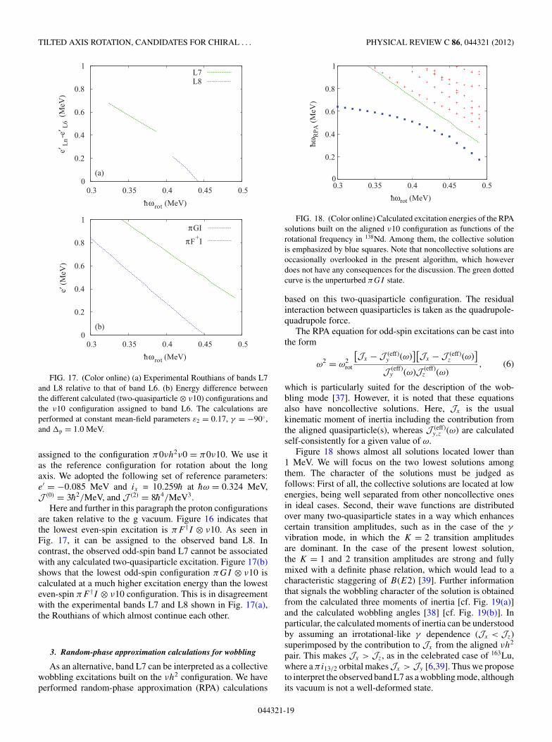
FIG. 17. (Color online) (a) Experimental Routhians of bands L7and L8 relative to that of band L6. (b) Energy difference betweenthe different calculated (two-quasiparticle ⊗ ν10) configurations andthe ν10 configuration assigned to band L6. The calculations areperformed at constant mean-field parameters ε2 = 0.17, γ = −90◦,and p = 1.0 MeV.
assigned to the configuration π0νh2ν0 = π0ν10. We use itas the reference configuration for rotation about the longaxis. We adopted the following set of reference parameters:e′ = −0.085 MeV and ix = 10.259h at hω = 0.324 MeV,J (0) = 3h2/MeV, and J (2) = 8h4/MeV3.
Here and further in this paragraph the proton configurationsare taken relative to the g vacuum. Figure 16 indicates thatthe lowest even-spin excitation is πF †I ⊗ ν10. As seen inFig. 17, it can be assigned to the observed band L8. Incontrast, the observed odd-spin band L7 cannot be associatedwith any calculated two-quasiparticle excitation. Figure 17(b)shows that the lowest odd-spin configuration πGI ⊗ ν10 iscalculated at a much higher excitation energy than the lowesteven-spin πF †I ⊗ ν10 configuration. This is in disagreementwith the experimental bands L7 and L8 shown in Fig. 17(a),the Routhians of which almost continue each other.
3. Random-phase approximation calculations for wobbling
As an alternative, band L7 can be interpreted as a collectivewobbling excitations built on the νh2 configuration. We haveperformed random-phase approximation (RPA) calculations
0
0.2
0.4
0.6
0.8
1
0.3 0.35 0.4 0.45 0.5
hωR
PA
(M
eV)
-
hωrot (MeV)-
FIG. 18. (Color online) Calculated excitation energies of the RPAsolutions built on the aligned ν10 configuration as functions of therotational frequency in 138Nd. Among them, the collective solutionis emphasized by blue squares. Note that noncollective solutions areoccasionally overlooked in the present algorithm, which howeverdoes not have any consequences for the discussion. The green dottedcurve is the unperturbed πGI state.
based on this two-quasiparticle configuration. The residualinteraction between quasiparticles is taken as the quadrupole-quadrupole force.
The RPA equation for odd-spin excitations can be cast intothe form
ω2 = ω2rot
[Jx − J (eff)
y (ω)][Jx − J (eff)
z (ω)]
J (eff)y (ω)J (eff)
z (ω), (6)
which is particularly suited for the description of the wob-bling mode [37]. However, it is noted that these equationsalso have noncollective solutions. Here, Jx is the usualkinematic moment of inertia including the contribution fromthe aligned quasiparticle(s), whereas J (eff)
y,z (ω) are calculatedself-consistently for a given value of ω.
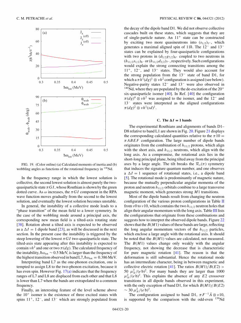
Figure 18 shows almost all solutions located lower than1 MeV. We will focus on the two lowest solutions amongthem. The character of the solutions must be judged asfollows: First of all, the collective solutions are located at lowenergies, being well separated from other noncollective onesin ideal cases. Second, their wave functions are distributedover many two-quasiparticle states in a way which enhancescertain transition amplitudes, such as in the case of the γ
vibration mode, in which the K = 2 transition amplitudesare dominant. In the case of the present lowest solution,the K = 1 and 2 transition amplitudes are strong and fullymixed with a definite phase relation, which would lead to acharacteristic staggering of B(E2) [39]. Further informationthat signals the wobbling character of the solution is obtainedfrom the calculated three moments of inertia [cf. Fig. 19(a)]and the calculated wobbling angles [38] [cf. Fig. 19(b)]. Inparticular, the calculated moments of inertia can be understoodby assuming an irrotational-like γ dependence (Jx < Jz)superimposed by the contribution to Jx from the aligned νh2
pair. This makes Jx > Jz, as in the celebrated case of 163Lu,where a πi13/2 orbital makesJx > Jy [6,39]. Thus we proposeto interpret the observed band L7 as a wobbling mode, althoughits vacuum is not a well-deformed state.
044321-19
C. M. PETRACHE et al. PHYSICAL REVIEW C 86, 044321 (2012)
0
20
40
60
80
0.3 0.35 0.4 0.45 0.5
J(h2 M
eV-1
)-
hωrot (MeV)-
(a) Jx
Jy(eff)
Jz(eff)
0
15
30
45
60
75
90
0.3 0.35 0.4 0.45 0.5
θ wob
, φ w
ob (
deg)
hωrot (MeV)-
(b) θwobφwob
FIG. 19. (Color online) (a) Calculated moments of inertia and (b)wobbling angles as functions of the rotational frequency in 138Nd.
In the frequency range in which the lowest solution iscollective, the second lowest solution is almost purely the two-quasiparticle state πGI , whose Routhian is shown by the greendotted curve. As ω increases, the πGI component in the RPAwave function moves gradually from the second to the lowestsolution, and eventually the lowest solution becomes unstable.
In general, the instability of a collective mode leads to a“phase transition” of the mean field to a lower symmetry. Inthe case of the wobbling mode around a principal axis, thecorresponding new mean field is a tilted-axis rotating state[38]. Rotation about a tilted axis is expected to be observedas a I = 1 dipole band [23], as will be discussed in the nextsection. In the present case the instability is triggered by thesteep lowering of the lowest πGI two-quasiparticle state. Thetilted-axis state appearing after this instability is expected tocontain νh2 and one or two π (dg). The calculated frequency ofthe instability, hωrot ∼ 0.5 MeV, is larger than the frequency ofthe highest transition observed in band L7, hωrot = 0.386 MeV.
Interpreting band L7 as the one-phonon excitation, one istempted to assign L8 to the two-phonon excitation, because ithas even spin. However Fig. 17(a) indicates that the frequencyranges of L7 and L8 are displaced from each other and that L8is lower than L7 when the bands are extrapolated to a commonfrequency.
Finally, an interesting feature of the level scheme abovethe 10+ isomer is the existence of three excited states withspins 11+, 12−, and 13− which are strongly populated from
the decay of the dipole band D1. We did not observe collectivecascades built on these states, which suggests that they areof single-particle nature. An 11+ state can be constructedby exciting two more quasineutrons into (s1/2)1+ , whichgenerates a maximal aligned spin of 11h. The 12− and 13−states can be explained by four-quasiparticle configurationswith two protons in (d5/2g7/2)6+ coupled to two neutrons in(h11/2s1/2)6− or (h11/2d3/2)7− , respectively. Such configurationswould explain the strong connecting transitions among the11+, 12−, and 13− states. They would also account forthe strong population from the 13− state of band D1, forwhich a πh1(dg)1 ⊗ νh2 configuration is assigned (see below).Negative-parity states 12− and 13− were also observed in140Nd, where they are populated by the de-excitation of the 20+six-quasiparticle isomer [40]. In Ref. [40] the configurationπ (dg)4 ⊗ νh2 was assigned to the isomer, and the 12− and13− states were interpreted as the aligned configurationsπ (dg)2 ⊗ νh1(sd)1.
C. The �I = 1 bands
The experimental Routhians and alignments of bands D1–D8 relative to band L1 are shown in Fig. 20. Figure 21 displaysthe corresponding calculated quantities relative to the π10 =πABEF configuration. The large number of dipole bandsoriginates from the combination of h11/2 protons, which alignwith the short axis, and h11/2 neutrons, which align with thelong axis. As a compromise, the rotational axis lies in theshort-long principal plane, being tilted away from the principalaxes by a large angle. The tilt breaks the Rx(π ) symmetrythat induces the signature quantum number, and one observesa I = 1 sequence of rotational states, i.e., a dipole band[5]. The rotational mode is predominantly of magnetic nature,because the mutually perpendicular angular momenta of theproton and neutron h11/2 orbitals combine to a large transversemagnetic moment, which generates strong M1 transitions.
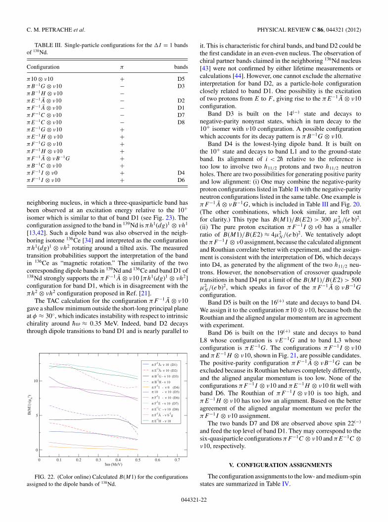
Most of the dipole bands result from changing the neutronconfiguration of the various proton configurations in Table IIfrom ν0 to ν10, which contains the two h11/2 neutron holes thatalign their angular momentum with the long axis. Table III liststhe configurations that originate from these combinations andsuggests how to interpret the observed dipole bands. Figure 22shows that the B(M1) values of these bands are large, reflectingthe long angular momentum vectors of the h11/2 particles,which enclose a large angle with the rotational axis. It shouldbe noted that the B(M1) values are calculated, not measured.The B(M1) values change only weakly with the angularfrequency, not showing the decrease that is characteristicfor pure magnetic rotation [41]. The reason is that thedeformation is still substantial. Hence the rotational modehas an intermediate character, being in between magnetic andcollective electric rotation [41]. The ratios B(M1)/B(E2) >
50 μ2N/(e b)2. For many bands they are larger than 1000
μ2N/(e b)2. This explains the absence of any E2 crossover
transitions in all dipole bands observed in this experiment,with the only exception of band D1, for which B(M1)/B(E2)∼ 30 μ2
N/(e b)2.The configuration assigned to band D1, πF−1A ⊗ ν10,
is supported by the comparison with the odd-even 139Nd
044321-20
TILTED AXIS ROTATION, CANDIDATES FOR CHIRAL . . . PHYSICAL REVIEW C 86, 044321 (2012)
0 0.2 0.4 0.6 0.8
0
1
2e′
(M
eV)
D1D2D3D4L1
0 0.2 0.4 0.6 0.8
0
4
i (h_
)i (
h_)
D1D2D3D4L1
0 0.2 0.4 0.6 0.8
h_ ω (MeV)
0
1
2
e′ (
MeV
)
π F-1A- - ν 10 (D1)
π E-1A- - ν 10 (D2)
π B-1G - ν 10 (D3)
π B-1H - ν 10
π F-1I - ν 0 (D4)
π ABEF - ν B-1G
π ABEF - ν F-1
A-
π ABEF (L1)
0 0.2 0.4 0.6 0.8
h_ ω (MeV)
-2
0
2
π F-1A- - ν 10 (D1)
π E-1A- - ν 10 (D2)
π B-1G - ν 10 (D3)
π B-1H - ν 10
π F-1I - ν 0 (D4)
π ABEF - ν B-1G
π ABEF - ν F-1A-
π ABEF (L1)
FIG. 20. (Color online) Experimental and calculated Routhians and single-particle alignments relative to band L1 for the I = 1 bandsD1–D4 of 138Nd. The line type indicates the parity: full (π = +) or dash-dotted (π = −). All calculated Routhians, except πABEIν0, areshifted by Eexp,L6(10+) − [Ecalc,ν10(ω = 0) − Ecalc,ν0(ω = 0)] in order to account for the energy needed for breaking a neutron pair.
0 0.2 0.4 0.6 0.8
-1
0
1
2
e′ (
MeV
)
D5D6D7D8L1
0 0.2 0.4 0.6 0.8
0
4
8
D5D6D7D8L1
0 0.2 0.4 0.6 0.8
h_ ω (MeV)
-1
0
1
2
e′ (
MeV
)
π 10 - ν 10 (D5)
π F-1I - ν 10 (D6)
π F-1C - ν 10 (D7)
π E-1C - ν 10 (D8)
π F-1A- - ν B-1
G
π E-1H - ν 10
π ABEF (L1)
0 0.2 0.4 0.6 0.8
h_ ω (MeV)
0
4
8
i (h_)
i (h_)
π 10 - ν 10 (D5)
π F-1I - ν 10 (D6)
π F-1C - ν 10 (D7)
π E-1C - ν 10 (D8)
π F-1A- - ν B-1
G
π E-1H - ν 10
π ABEF (L1)
FIG. 21. (Color online) Experimental and calculated Routhians and single-particle alignments relative to band L1 for the I = 1 bandsD5–D8 of 138Nd. The line type indicates the parity: full (π = +) or dash-dotted (π = −). All calculated Routhians, except πABEIν0, areshifted by Eexp,L6(10+) − [Ecalc,ν10(ω = 0) − Ecalc,ν0(ω = 0)] in order to account for the energy needed for breaking a neutron pair.
044321-21
C. M. PETRACHE et al. PHYSICAL REVIEW C 86, 044321 (2012)
TABLE III. Single-particle configurations for the I = 1 bandsof 138Nd.
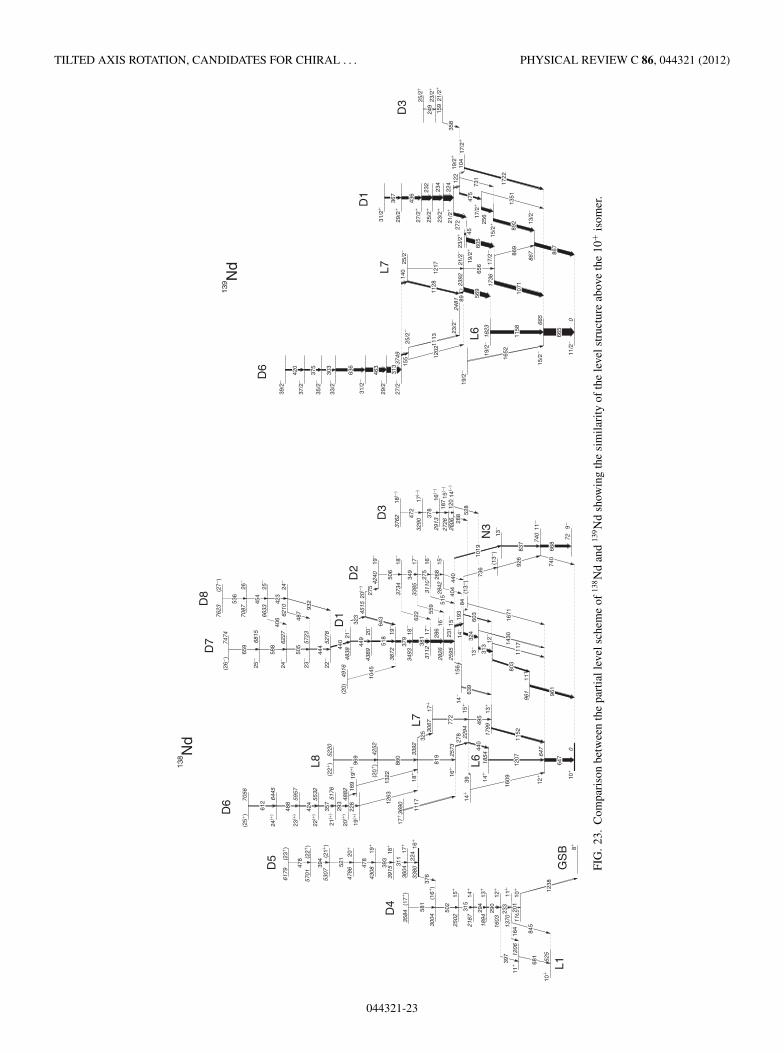
neighboring nucleus, in which a three-quasiparticle band hasbeen observed at an excitation energy relative to the 10+isomer which is similar to that of band D1 (see Fig. 23). Theconfiguration assigned to the band in 139Nd is πh1(dg)1 ⊗ νh1
[13,42]. Such a dipole band was also observed in the neigh-boring isotone 136Ce [34] and interpreted as the configurationπh1(dg)1 ⊗ νh2 rotating around a tilted axis. The measuredtransition probabilities support the interpretation of the bandin 136Ce as “magnetic rotation.” The similarity of the twocorresponding dipole bands in 139Nd and 136Ce and band D1 of138Nd strongly supports the πF−1A ⊗ ν10 [πh1(dg)1 ⊗ νh2]configuration for band D1, which is in disagreement with theπh2 ⊗ νh2 configuration proposed in Ref. [21].
The TAC calculation for the configuration πF−1A ⊗ ν10gave a shallow minimum outside the short-long principal planeat φ ≈ 30◦, which indicates instability with respect to intrinsicchirality around hω ≈ 0.35 MeV. Indeed, band D2 decaysthrough dipole transitions to band D1 and is nearly parallel to
0 0.1 0.2 0.3 0.4 0.5 0.6 0.7_hω (MeV)
0
5
10
B(M
1) (
µ n²)
π F-1A- - ν 10 (D1)
π E-1A- - ν 10 (D2)
π B-1G - ν 10 (D3)
π B-1H - ν 10
π F-1I - ν 0 (D4)
π 10 - ν 10 (D5)
π F-1I - ν 10 (D6)
π F-1E - ν 10 (D7)
π E-1C - ν 10 (D8)
π F-1A- - ν b-1
g
π E-1H - ν 10
FIG. 22. (Color online) Calculated B(M1) for the configurationsassigned to the dipole bands of 138Nd.
it. This is characteristic for chiral bands, and band D2 could bethe first candidate in an even-even nucleus. The observation ofchiral partner bands claimed in the neighboring 136Nd nucleus[43] were not confirmed by either lifetime measurements orcalculations [44]. However, one cannot exclude the alternativeinterpretation for band D2, as a particle-hole configurationclosely related to band D1. One possibility is the excitationof two protons from E to F , giving rise to the πE−1A ⊗ ν10configuration.
Band D3 is built on the 14(−) state and decays tonegative-parity nonyrast states, which in turn decay to the10+ isomer with ν10 configuration. A possible configurationwhich accounts for its decay pattern is πB−1G ⊗ ν10.
Band D4 is the lowest-lying dipole band. It is built onthe 10+ state and decays to band L1 and to the ground-stateband. Its alignment of i < 2h relative to the reference istoo low to involve two h11/2 protons and two h11/2 neutronholes. There are two possibilities for generating positive parityand low alignment: (i) One may combine the negative-parityproton configurations listed in Table II with the negative-parityneutron configurations listed in the same table. One example isπF−1A ⊗ νB−1G, which is included in Table III and Fig. 20.(The other combinations, which look similar, are left outfor clarity.) This type has B(M1)/B(E2) > 300 μ2
N/(e b)2.(ii) The pure proton excitation πF−1I ⊗ ν0 has a smallerratio of B(M1)/B(E2) ≈ 4μ2
N/(e b)2. We tentatively adoptthe πF−1I ⊗ ν0 assignment, because the calculated alignmentand Routhian correlate better with experiment, and the assign-ment is consistent with the interpretation of D6, which decaysinto D4, as generated by the alignment of the two h11/2 neu-trons. However, the nonobservation of crossover quadrupoletransitions in band D4 put a limit of the B(M1)/B(E2) > 500μ2
N/(e b)2, which speaks in favor of the πF−1A ⊗ νB−1G
configuration.Band D5 is built on the 16(+) state and decays to band D4.
We assign it to the configuration π10 ⊗ ν10, because both theRouthian and the aligned angular momentum are in agreementwith experiment.
Band D6 is built on the 19(+) state and decays to bandL8 whose configuration is νE−1G and to band L3 whoseconfiguration is πE−1G. The configurations πF−1I ⊗ ν10and πE−1H ⊗ ν10, shown in Fig. 21, are possible candidates.The positive-parity configuration πF−1A ⊗ νB−1G can beexcluded because its Routhian behaves completely differently,and the aligned angular momentum is too low. None of theconfigurations πF−1I ⊗ ν10 and πE−1H ⊗ ν10 fit well withband D6. The Routhian of πF−1I ⊗ ν10 is too high, andπE−1H ⊗ ν10 has too low an alignment. Based on the betteragreement of the aligned angular momentum we prefer theπF−1I ⊗ ν10 assignment.
The two bands D7 and D8 are observed above spin 22(−)
and feed the top level of band D1. They may correspond to thesix-quasiparticle configurations πF−1C ⊗ ν10 and πE−1C ⊗ν10, respectively.
V. CONFIGURATION ASSIGNMENTS
The configuration assignments to the low- and medium-spinstates are summarized in Table IV.
044321-22
TILTED AXIS ROTATION, CANDIDATES FOR CHIRAL . . . PHYSICAL REVIEW C 86, 044321 (2012)
FIG
.23
.C
ompa
riso
nbe
twee
nth
epa
rtia
llev
elsc
hem
eof
138N
dan
d13
9N
dsh
owin
gth
esi
mila
rity
ofth
ele
vels
truc
ture
abov
eth
e10
+is
omer
.
044321-23
C. M. PETRACHE et al. PHYSICAL REVIEW C 86, 044321 (2012)
TABLE IV. Configuration assignments to the low- and medium-spin bands of 138Nd in terms of particle-hole excitations with respect to theπABEF = π10 reference configuration assigned to band L1 or the corresponding quasiproton vacuum for small finite pairing. The rotationaxis is also indicated, which can be tilted (TAC) or parallel to a principal axis (PAC) of the intrinsic reference system of the nucleus. In the caseof PAC, l and s indicate the long and short axes, respectively.
Band Intensity (%) Configuration Rotation type States Comments
g band 100 π0 ⊗ ν0 2+−8+
γ band γ band 2+−4+ Decays to g bandN1 39 π0 ⊗ νB−1Hν10 PAC-l 5−
1 −15− Decays to g bandN2 14 πB−1Hπ10 ⊗ ν0 PAC-s 8−
L1 64 π10 ⊗ ν0 PAC-s 10+−20+ Decays to N2, N3L2 6 πF −1Hπ10 ⊗ ν0 or πE†F †π10 ⊗ ν0 PAC-s 14+, 16+, 18+ Decays to L1L3 2 πE−1Gπ10 ⊗ ν0 or πF †Hπ10 ⊗ ν0 PAC-s 14+−20+ Decays to L1, L4L4 2 πE−1Hπ10 ⊗ ν0 PAC-s 13+, 15+ Decays to L1, L3L5 8 πF −1Cπ10 ⊗ ν0 or π10 ⊗ νh2 PAC-s 15(−)−23(−) Decays to L1, D4L6 24 π0 ⊗ ν10 PAC-l 10+−14+ Band head is isomericL7 11 wobbling or π0 ⊗ νF −1Gν10 or πGIπ0 ⊗ ν10 PAC-l 13+−17+ Decays to L6L8 2 π0 ⊗ νE−1Gν10 or πF †Iπ0 ⊗ ν10 PAC-l 16+−22+ Decays to L7D1 21 πF −1Aπ10 ⊗ ν10 TAC 13−−21− Decays to N4, L8D2 2 πE−1Aπ10 ⊗ ν10 or chiral TAC 15−−19− Decays to D1D3 1 πB−1Gπ10 ⊗ ν10 TAC 14−−18− Decays to nonyrast π = −D4 5 πF −1Iπ10 ⊗ ν0 or πF −1A ⊗ νb−1g TAC 10+−17+ Decays to L1 and GSBD5 1 π10 ⊗ ν10 TAC 16(+)−23(+) Decays to D4 and π = −D6 4 πF −1Iπ10 ⊗ ν10 or πE−1H ⊗ ν10 TAC 19(+)−(25+) Decays to L7D7 3 πF −1Cπ10 ⊗ ν10 TAC 22(−)−(26−) Decays to D1D8 2 πE−1Cπ10 ⊗ ν10 TAC 24(−)−(27−) Decays to D7
VI. SUMMARY
High-spin states in 138Nd have been populated in thereaction 94Zr(48Ca, 4n) at beam energies of 188 and 195 MeV.The GASP spectrometer was used to detect the γ -ray coinci-dences. A very rich and rather complete level scheme wasconstructed. Most of the existing information was confirmed.New bands were observed at low and medium spins (fournegative-parity bands at low spins, eight bands of quadrupoletransitions, and eight bands of dipole transitions at mediumspins). The observed bands were discussed using the CSM,TAC and RPA approaches. The possible existence of awobbling excitation was suggested, which would be the first inthis mass region. Configuration assignments for the differentbands were proposed that correspond to rotation either arounda principal axis or a tilted axis of the intrinsic reference system
of one and the same nucleus. The orientation depends on thepresence in the configurations of protons and neutrons in theh11/2 orbitals. Two dipole bands have properties which areconsistent with a dynamic chirality. They represent candidatesfor chiral partners in an even-even nucleus. The consistency ofthe configuration assignments to the observed bands stronglysuggests the existence of a stable triaxial deformation atmedium spin in this mass region.
ACKNOWLEDGMENTS
This work was supported by the Japan Society for thePromotion of Science (JSPS) under the “FY2011 JSPSInvitation Fellowship Program for Research in Japan,” IDNo. L-11516, and US Department of Energy Grant No.DE-FG02-95ER4093.
[1] L. Wilets and M. Jean, Phys. Rev. 102, 788 (1956).[2] A. S. Davydov and A. A. Chaban, Nucl. Phys. 20, 499 (1960);
8, 237 (1958).[3] A. Bohr and B. R. Mottelson, Nuclear Structure (Benjamin,
Reading, MA, 1975), Vol. II.[4] S. Frauendorf and J. Meng, Nucl. Phys. A 617, 131 (1997).[5] S. Frauendorf, Rev. Mod. Phys. 73, 463 (2001).[6] S. W. Ødegard et al., Phys. Rev. Lett. 86, 5866 (2001).[7] C. M. Petrache, D. Bazzacco, S. Lunardi, C. Rossi Alvarez,
G. de Angelis, M. De Poli, D. Bucurescu, C. A. Ur, P. B. Semmes,and R. Wyss, Nucl. Phys. A 597, 106 (1996).
[8] S. Mukhopadhyay et al., Phys. Rev. Lett. 99, 172501(2007).
[9] C. M. Petrache et al., Phys. Lett. B 373, 275 (1996).[10] C. M. Petrache et al., Nucl. Phys. A 617, 228 (1997).[11] C. M. Petrache et al., Phys. Rev. C 61, 011305(R) (1999).[12] C. M. Petrache et al., Phys. Rev. C 72, 064318 (2005).[13] S. Bhowal et al., Phys. Rev. C 84, 024313 (2011).[14] S. Lunardi et al., Phys. Rev. C 69, 054302 (2004).[15] A. Neußer et al., Phys. Rev. C 70, 064315 (2004).[16] C. M. Petrache et al. (private communication).[17] N. Yoshikawa, Nucl. Phys. A 243, 143 (1974).
TILTED AXIS ROTATION, CANDIDATES FOR CHIRAL . . . PHYSICAL REVIEW C 86, 044321 (2012)
[18] J. Deslauriers, S. C. Gujrathi, and S. K. Mark, Z. Phys. A 303,151 (1981).
[19] M. Muller-Veggian, H. Beuscher, R. M. Lieder, Y. Gono, D. R.Haenni, A. Neskakis, and C. Mayer-Boricke, Z. Phys. A 290, 43(1979).
[20] M. Muller-Veggian, H. Beuscher, D. R. Haenni, R. M. Lieder,A. Neskakis, and C. Mayer-Boricke, Nucl. Phys. A 344, 89(1980).
[21] G. de Angelis et al., Phys. Rev. C 49, 2990 (1994).[22] R. Bengtsson and S. Frauendorf, Nucl. Phys. A 327, 139
(1979).[23] S. Frauendorf, Nucl. Phys. A 557, 250c (1993).[24] S. Frauendorf, Nucl. Phys. A 677, 115 (2000).[25] T. Bengtsson and I. Ragnarsson, Nucl. Phys. A 436, 14 (1985).[26] I. Ragnarsson, Nucl. Phys. A 591, 387 (1995).[27] A. V. Afanasjev, D. B. Fossan, G. J. Lane, and I. Ragnarsson,
Phys. Rep. 322, 1 (1999).[28] I. Ragnarsson, V. P. Janzen, D. B. Fossan, N. C. Schmeing, and
R. Wadsworth, Phys. Rev. Lett. 74, 3935 (1995).[29] R. Bengtsson, S. Frauendorf, and F. R. May, At. Data Nucl. Data
Tables 35, 15 (1986).[30] S. Frauendorf, Y. Gu, and J. Sun, Int. J. Mod. Phys. E 20, 465
(2011).
[31] Y. R. Shimizu et al., Rev. Mod. Phys. 61, 131 (1989).[32] S. Frauendorf and C. M. Petrache [Phys. Rev C (to be
published)].[33] C. M. Petrache et al., Phys. Lett. B 373, 275 (1996).[34] S. Lakshmi, H. C. Jain, P. K. Joshi, Amita, P. Agarwal, A. K.
Jain, and S. S. Malik, Phys. Rev. C 66, 041303(R) (2002).[35] M. Matsuzaki, Y. R. Shimizu, and K. Matsuyanagi, Phys. Rev.
C 69, 034325 (2004).[36] B. G. Carlsson and I. Ragnarsson, Phys. Rev. C 74, 011302(R)
(2006).[37] E. R. Marshalek, Nucl. Phys. A 331, 429 (1979).[38] M. Matsuzaki and S.-I. Ohtsubo, Phys. Rev. C 69, 064317
(2004).[39] M. Matsuzaki, Y. R. Shimizu, and K. Matsuyanagi, Phys. Rev.
C 65, 041303(R) (2002).[40] C. M. Petrache et al., Phys. Rev. C 74, 034304
(2006).[41] S. Frauendorf, Rev. Mod. Phys. 73, 463 (2001).[42] S. Kumar, R. Palit, H. C. Jain, I. Mazumdar, P. K. Joshi, S. Roy,
A. Y. Deo, Z. Naik, S. S. Malik, and A. K. Jain, Phys. Rev. C76, 014306 (2007).
[43] E. Mergel et al., Eur. Phys. J. A 15, 417 (2002).[44] S. Mukhopadhyay et al., Phys. Rev. C 78, 034311 (2008).