21
DIGITAL ANALOG CONVERSTERS

8/6/2019 Tim Eric 1
http://slidepdf.com/reader/full/tim-eric-1 1/21
DIGITAL ANALOG CONVERSTERS

8/6/2019 Tim Eric 1
http://slidepdf.com/reader/full/tim-eric-1 2/21
DAC
Changes a digital value back into an analog voltage
Digital-to-analog conversion can be achieved
using a network of resistors called ³ladder
network´.
ADCObtains a digital value changes a digital value
back into an analog voltage
8/6/2019 Tim Eric 1
http://slidepdf.com/reader/full/tim-eric-1 3/21
Ladder Network
One Popular scheme uses a network resistors.
Accepts inputs of binary values at, typically, 0V
or Vref , and provider an output voltage proportionalto the binary input value.

8/6/2019 Tim Eric 1
http://slidepdf.com/reader/full/tim-eric-1 4/21
A ladder network with four input voltages, representing 4
bits of digital data and dc voltage output.
R R R R
Vi(1)
D1
Vi(2)
D2
Vi(3)
D3
Vi(0)
D0
Digital input
8/6/2019 Tim Eric 1
http://slidepdf.com/reader/full/tim-eric-1 5/21
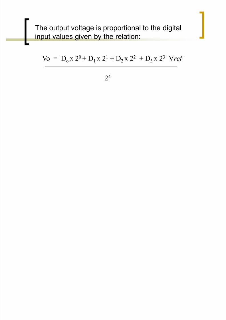
The output voltage is proportional to the digital
input values given by the relation:
Vo = Do x 20 + D1 x 21 + D2 x 22 + D3 x 23 Vref
24

8/6/2019 Tim Eric 1
http://slidepdf.com/reader/full/tim-eric-1 6/21

8/6/2019 Tim Eric 1
http://slidepdf.com/reader/full/tim-eric-1 7/21
In the above example the output voltage resultingshould be:
V0 = 0 x 1 + 1 x 2 + 1 x 4 + 0 x 8 (16 V) = 6 V
16
8/6/2019 Tim Eric 1
http://slidepdf.com/reader/full/tim-eric-1 8/21
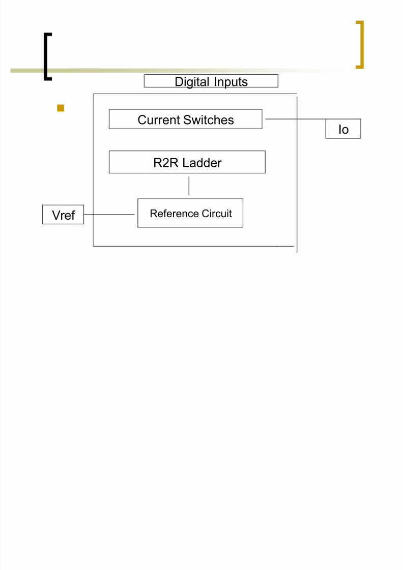
Current Switches
R2R Ladder
Reference CircuitVref
Digital Inputs
Io

8/6/2019 Tim Eric 1
http://slidepdf.com/reader/full/tim-eric-1 9/21
DUAL SLOPE CONVERSION
Popular method for converting an analog
voltage into digital value
The analog voltage to be converted is applied
through an electronic switch to an integrator or
ramp-generator circuit.

8/6/2019 Tim Eric 1
http://slidepdf.com/reader/full/tim-eric-1 10/21
Ladder Voltage
Count Interval
Start Stop Count
Analog Voltage

8/6/2019 Tim Eric 1
http://slidepdf.com/reader/full/tim-eric-1 11/21
LADDER NETWORK CONVERSION
method for converting an analog voltage intodigital with counter and comparator circuits
A digital counter advances from zero count while a ladder network driven by the counter
outputs a staircase voltage.

8/6/2019 Tim Eric 1
http://slidepdf.com/reader/full/tim-eric-1 12/21
Timer IC Unit Operation
8/6/2019 Tim Eric 1
http://slidepdf.com/reader/full/tim-eric-1 13/21
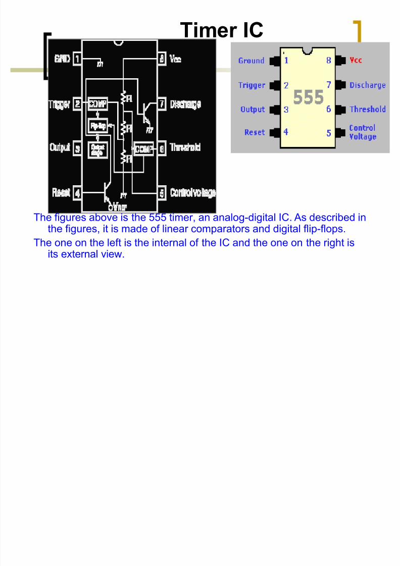
Timer IC
The figures above is the 555 timer, an analog-digital IC. As described inthe figures, it is made of linear comparators and digital flip-flops.
The one on the left is the internal of the IC and the one on the right isits external view.
8/6/2019 Tim Eric 1
http://slidepdf.com/reader/full/tim-eric-1 14/21
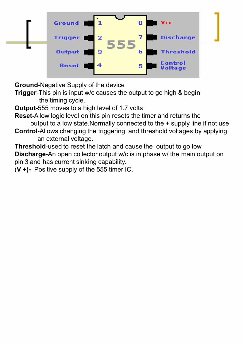
Ground-Negative Supply of the deviceTr igger -This pin is input w/c causes the output to go high & begin
the timing cycle.
Output-555 moves to a high level of 1.7 volts
Reset- A low logic level on this pin resets the timer and returns the
output to a low state.Normally connected to the + supply line if not use
Control-Allows changing the triggering and threshold voltages by applying
an external voltage.
Threshold-used to reset the latch and cause the output to go low
Dischar ge-An open collector output w/c is in phase w/ the main output on
pin 3 and has current sinking capability.
(V +)- Positive supply of the 555 timer IC.

8/6/2019 Tim Eric 1
http://slidepdf.com/reader/full/tim-eric-1 15/21
Multivibrators
Two-state devices called multivibrators
are used extensively in digital electronics.
The bistable multivibrators are called flip-flops and are the basic memory devices used
in sequential logic. Other two-state devices
include the astable multivibrator which serves
as an oscillator and the monostablemultivibrator ("one-shot" multivibrator) which
can serve as a pulse source.
8/6/2019 Tim Eric 1
http://slidepdf.com/reader/full/tim-eric-1 16/21
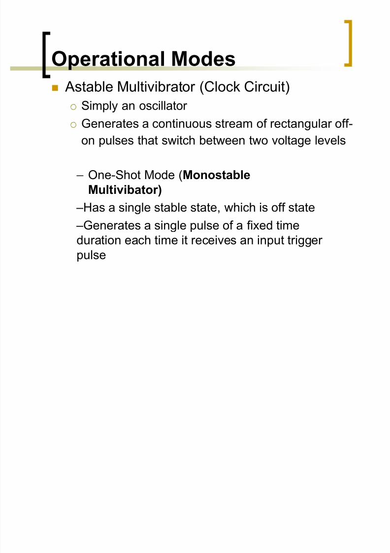
Operational Modes Astable Multivibrator (Clock Circuit)
Simply an oscillator
Generates a continuous stream of rectangular off-
on pulses that switch between two voltage levels
± One-Shot Mode (Monostable
Multivibator)
±Has a single stable state, which is off state
±Generates a single pulse of a fixed time
duration each time it receives an input trigger
pulse
8/6/2019 Tim Eric 1
http://slidepdf.com/reader/full/tim-eric-1 17/21
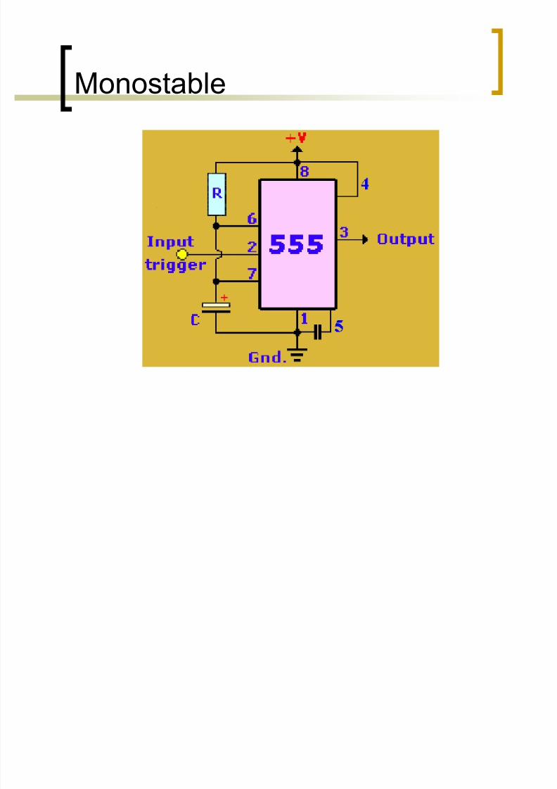
M
onostable
8/6/2019 Tim Eric 1
http://slidepdf.com/reader/full/tim-eric-1 18/21
M
onostable monostable timer is a one-stable timer; that is, it
returns to its original (stable) state (off) after a
certain period of time. Monostable operation is
characterized by the clothes iron, which switches
itself off after being unattended for 10 minutes.
Each time the iron is moved, a small sensor resets
the timer to zero to begin another count. The iron
remains on as long as it is moved within the 10-minute limit.
8/6/2019 Tim Eric 1
http://slidepdf.com/reader/full/tim-eric-1 19/21
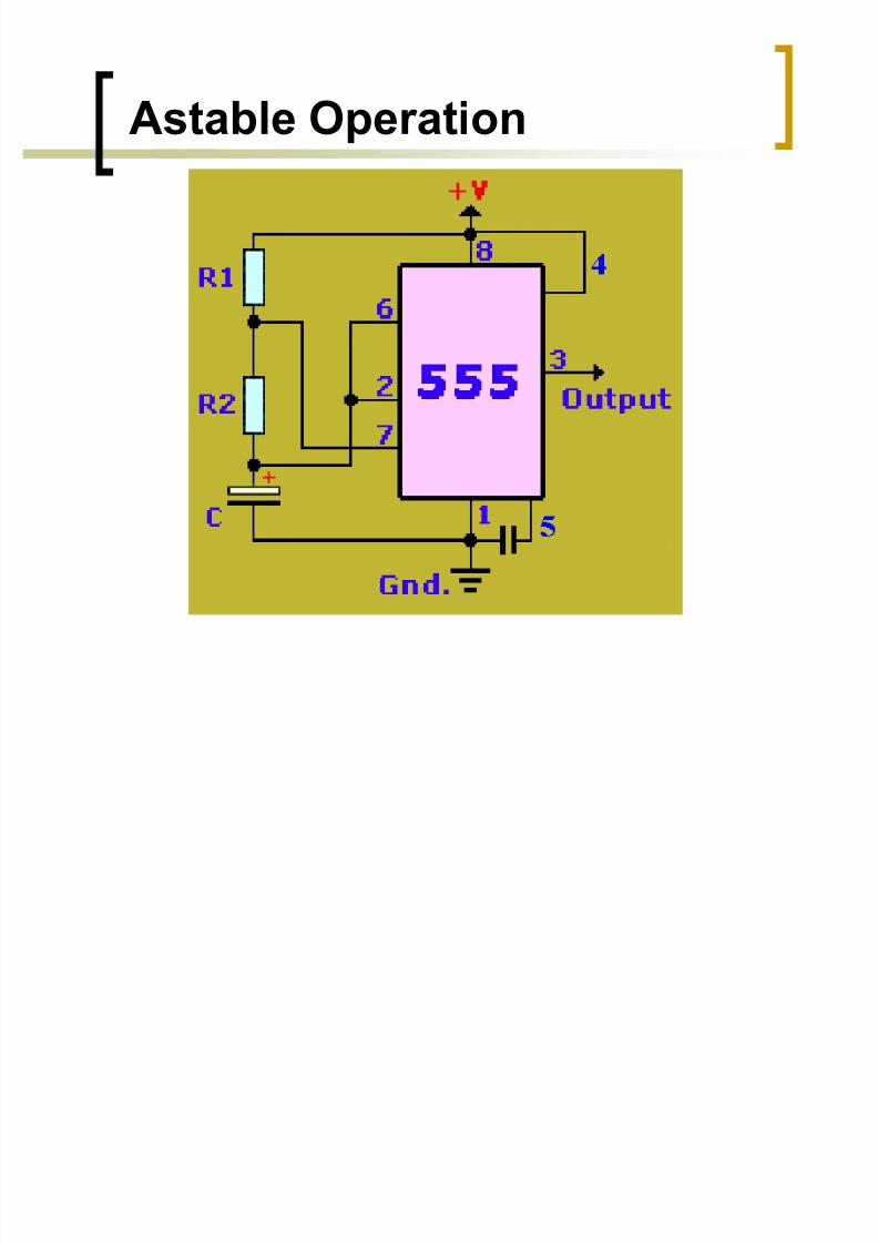
Astable Operation

8/6/2019 Tim Eric 1
http://slidepdf.com/reader/full/tim-eric-1 20/21
AstableOne that is constantly pulsing, never staying
in one state or the other. It is constantly
switching between its two states. The flashing
light or pulsing buzzer that warns that the
seat belts are not fastened when you start a
car is an example of astable operation. In this
mode, the output pulse is fed back into the
chip to trigger another pulse, and the the
result is a continuous pulsed signal.

8/6/2019 Tim Eric 1
http://slidepdf.com/reader/full/tim-eric-1 21/21
Reported By:
Chris Pactolerin
BS-Computer Science 4


