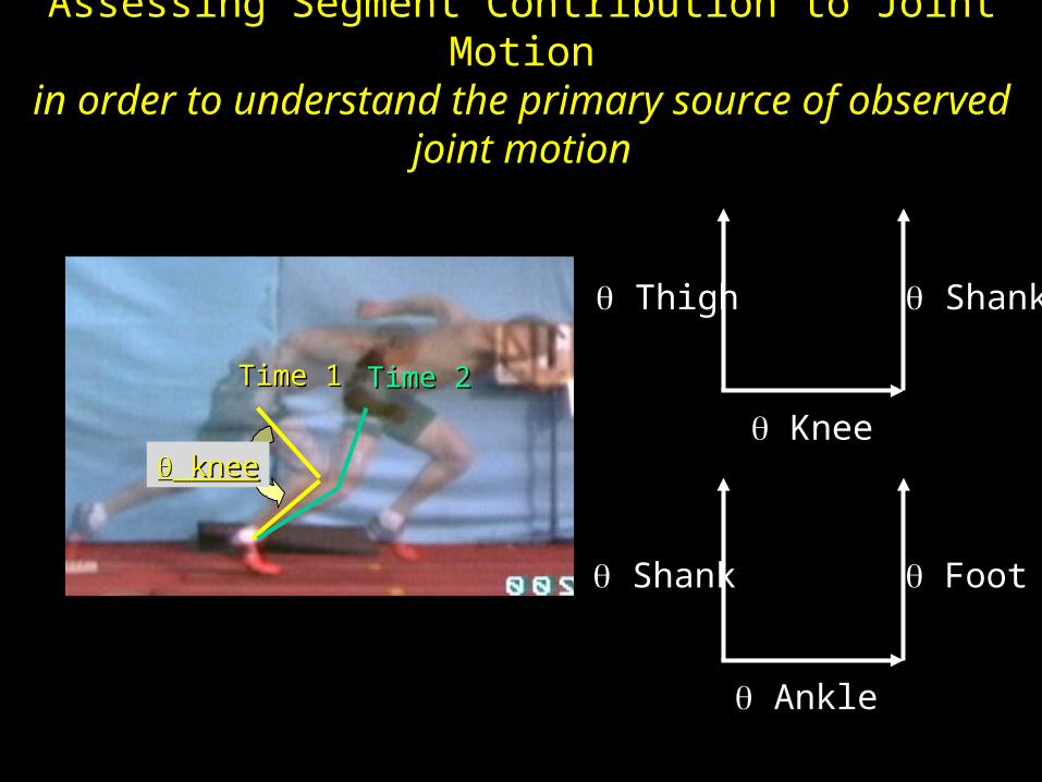
Time 1 shank thigh Knee Segment Angles are ABSOLUTE ANGLES , measured with respect to a (stationary) global vertical or horizontal reference axis. Joint Angles are RELATIVE ANGLES , measured between two adjacent segments with the angle’s vertex at the joint center. Angular Kinematics
Transcript
Time 1
shank
thigh Knee
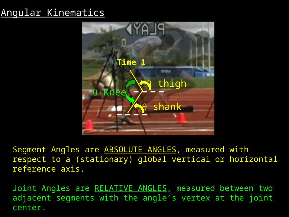
Segment Angles are ABSOLUTE ANGLES, measured with respect to a (stationary) global vertical or horizontal reference axis.
Joint Angles are RELATIVE ANGLES, measured between two adjacent segments with the angle’s vertex at the joint center.
Angular Kinematics
Time 1 Time 2
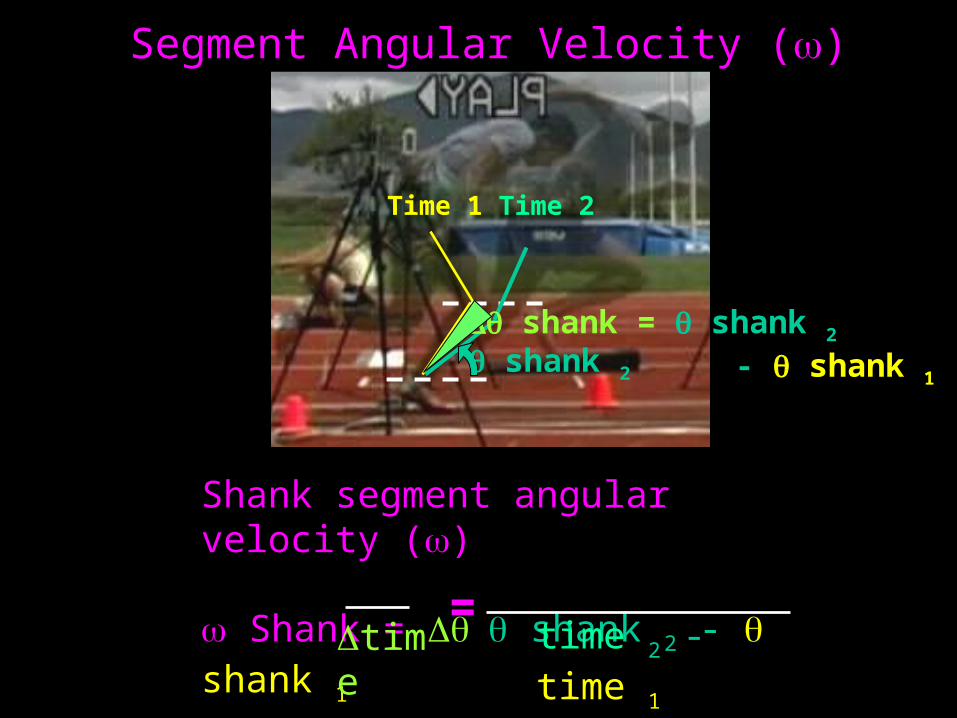
shank = shank 2 - shank 1
shank 2
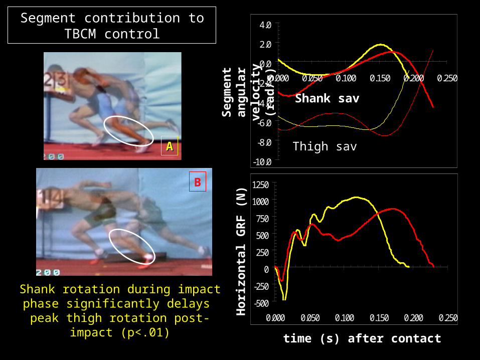
Shank segment angular velocity ()
Shank = shank 2 - shank
1
time 2 - time 1
time
=
Segment Angular Velocity ()
Calculating Segment Angular Position with segment endpoint coordinate data (x, y)
(0.65, 0.90)
(0.85, 0.50)
(0, 0) +X
+Y
Calculating JOINT Angular Position with Segment Angular Position Data
+Y
(0, 0) +X
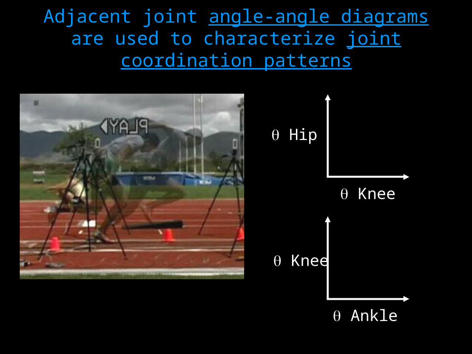
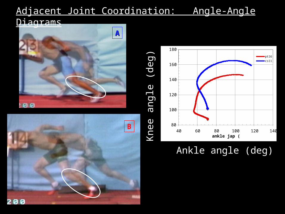
Adjacent joint angle-angle diagrams are used to characterize joint coordination
patterns
Knee
Hip
Knee
Ankle
100
120
140
160
180
200
100 120 140 160 180 200
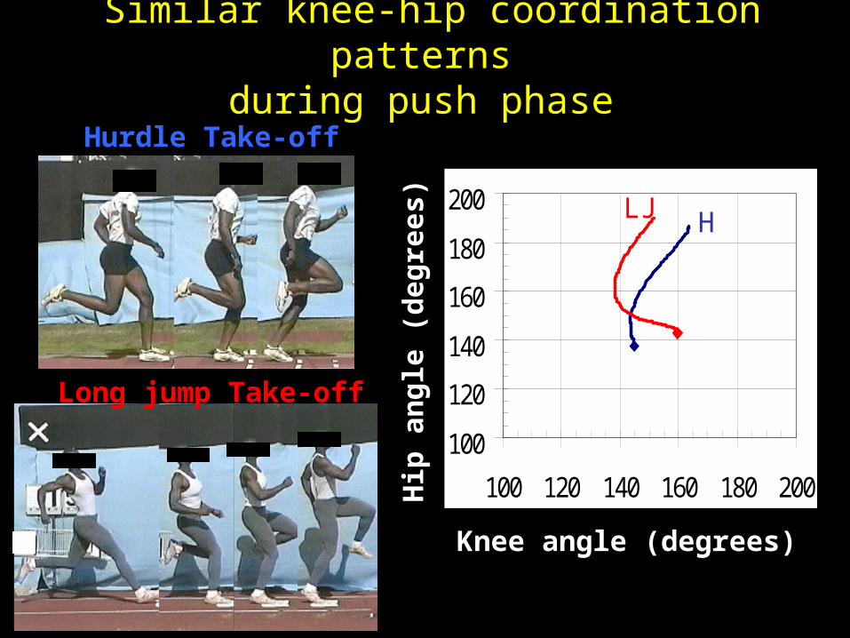
Knee angle (degrees)
Hip
an
gle
(d
eg
rees)
Similar knee-hip coordination patterns during push phase
Hurdle Take-off
Long jump Take-off
HLJ
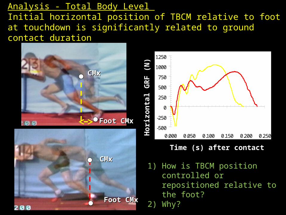
Analysis - Total Body Level Initial horizontal position of TBCM relative to foot at touchdown is significantly related to ground contact duration
-500
-250
0
250
500
750
1000
1250
0.000 0.050 0.100 0.150 0.200 0.250
Time (s) after contactH
oriz
onta
l GR
F (
N)
CMxCMx
Foot CMxFoot CMx
CMxCMx
Foot CMxFoot CMx
1) How is TBCM position controlled or repositioned relative to the foot?
2) Why?
Assessing Segment Contribution to Joint Motionin order to understand the primary source of