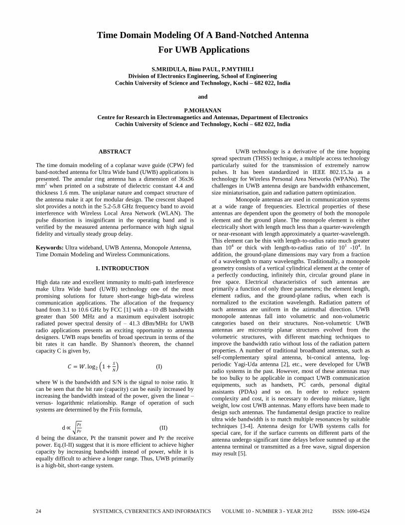
Time Domain Modeling Of A Band-Notched Antenna
For UWB Applications
S.MRIDULA, Binu PAUL, P.MYTHILI
Division of Electronics Engineering, School of Engineering
Cochin University of Science and Technology, Kochi – 682 022, India
and
P.MOHANAN
Centre for Research in Electromagnetics and Antennas, Department of Electronics
Cochin University of Science and Technology, Kochi – 682 022, India
ABSTRACT
The time domain modeling of a coplanar wave guide (CPW) fed
band-notched antenna for Ultra Wide band (UWB) applications is
presented. The annular ring antenna has a dimension of 36x36
mm2 when printed on a substrate of dielectric constant 4.4 and
thickness 1.6 mm. The uniplanar nature and compact structure of
the antenna make it apt for modular design. The crescent shaped
slot provides a notch in the 5.2-5.8 GHz frequency band to avoid
interference with Wireless Local Area Network (WLAN). The
pulse distortion is insignificant in the operating band and is
verified by the measured antenna performance with high signal
fidelity and virtually steady group delay.
Keywords: Ultra wideband, UWB Antenna, Monopole Antenna,
Time Domain Modeling and Wireless Communications.
1. INTRODUCTION
High data rate and excellent immunity to multi-path interference
make Ultra Wide band (UWB) technology one of the most
promising solutions for future short-range high-data wireless
communication applications. The allocation of the frequency
band from 3.1 to 10.6 GHz by FCC [1] with a –10 dB bandwidth
greater than 500 MHz and a maximum equivalent isotropic
radiated power spectral density of – 41.3 dBm/MHz for UWB
radio applications presents an exciting opportunity to antenna
designers. UWB reaps benefits of broad spectrum in terms of the
bit rates it can handle. By Shannon's theorem, the channel
capacity C is given by,
𝐶 = 𝑊. log2 1 +𝑆
𝑁 (I)
where W is the bandwidth and S/N is the signal to noise ratio. It
can be seen that the bit rate (capacity) can be easily increased by
increasing the bandwidth instead of the power, given the linear –
versus- logarithmic relationship. Range of operation of such
systems are determined by the Friis formula,
d ∝ 𝑃𝑡
𝑃𝑟 (II)
d being the distance, Pt the transmit power and Pr the receive
power. Eq.(I-II) suggest that it is more efficient to achieve higher
capacity by increasing bandwidth instead of power, while it is
equally difficult to achieve a longer range. Thus, UWB primarily
is a high-bit, short-range system.
UWB technology is a derivative of the time hopping
spread spectrum (THSS) technique, a multiple access technology
particularly suited for the transmission of extremely narrow
pulses. It has been standardized in IEEE 802.15.3a as a
technology for Wireless Personal Area Networks (WPANs). The
challenges in UWB antenna design are bandwidth enhancement,
size miniaturisation, gain and radiation pattern optimization.
Monopole antennas are used in communication systems
at a wide range of frequencies. Electrical properties of these
antennas are dependent upon the geometry of both the monopole
element and the ground plane. The monopole element is either
electrically short with length much less than a quarter-wavelength
or near-resonant with length approximately a quarter-wavelength.
This element can be thin with length-to-radius ratio much greater
than 104 or thick with length-to-radius ratio of 101 -104. In
addition, the ground-plane dimensions may vary from a fraction
of a wavelength to many wavelengths. Traditionally, a monopole
geometry consists of a vertical cylindrical element at the center of
a perfectly conducting, infinitely thin, circular ground plane in
free space. Electrical characteristics of such antennas are
primarily a function of only three parameters; the element length,
element radius, and the ground-plane radius, when each is
normalized to the excitation wavelength. Radiation pattern of
such antennas are uniform in the azimuthal direction. UWB
monopole antennas fall into volumetric and non-volumetric
categories based on their structures. Non-volumetric UWB
antennas are microstrip planar structures evolved from the
volumetric structures, with different matching techniques to
improve the bandwidth ratio without loss of the radiation pattern
properties. A number of traditional broadband antennas, such as
self-complementary spiral antenna, bi-conical antenna, log-
periodic Yagi-Uda antenna [2], etc., were developed for UWB
radio systems in the past. However, most of these antennas may
be too bulky to be applicable in compact UWB communication
equipments, such as handsets, PC cards, personal digital
assistants (PDAs) and so on. In order to reduce system
complexity and cost, it is necessary to develop miniature, light
weight, low cost UWB antennas. Many efforts have been made to
design such antennas. The fundamental design practice to realize
ultra wide bandwidth is to match multiple resonances by suitable
techniques [3-4]. Antenna design for UWB systems calls for
special care, for if the surface currents on different parts of the
antenna undergo significant time delays before summed up at the
antenna terminal or transmitted as a free wave, signal dispersion
may result [5].
SYSTEMICS, CYBERNETICS AND INFORMATICS VOLUME 10 - NUMBER 3 - YEAR 201224 ISSN: 1690-4524
Frequency (GHz)
2 4 6 8 10 12 14 16 18
Re
fle
ctio
n C
oe
ffic
ien
t (d
B)
-35
-30
-25
-20
-15
-10
-5
0
The UWB printed monopole antenna consists of a
monopole patch and a ground plane, both printed on the same or
opposite side of a substrate, while a microstrip line or CPW is
located in the middle of the ground plane to feed the monopole
patch. Compared with the ultra wide band metal-plate monopole
antenna, the UWB printed monopole antenna does not need a
perpendicular ground plane. Therefore, it is of smaller volume
and is suitable for integrating with monolithic microwave
integrated circuits (MMIC). To broaden the bandwidth of this
kind of antennas, a number of monopole shapes have been
developed, such as heart-shape, U-shape, circular-shape and
elliptical-shape etc. The UWB printed monopoles are more
suitable for small portable devices where volume constraint is a
significant factor.
Coplanar waveguide (CPW) fed antennas have the
advantage of a balanced structure, since the feed lines and the
radiating structure are on the same side of the substrate [6-7].
CPW fed slot antennas are also very good candidates for UWB
applications. The antennas discussed in [8] use a large slot for
bandwidth enhancement and L or T shapes for size reduction. A
CPW fed tapered ring slot antenna which can achieve a relatively
large bandwidth is introduced in [9]. The wide band slot antenna
[10] uses a large aperture and a modified microstrip feed to create
multiple resonances. In another technique, a rotated slot is
proposed [11] wherein two modes of close resonances are excited
by a microstrip feed line. A tapered slot feeding structure is used
to transform the guided waves to free space waves in [12]. In
[13], a microstrip fed triangular slot antenna with a double T
shaped tuning stub is introduced. The double T shaped stub is
fully positioned within the slot region on the opposite side of the
triangular slot. But the antenna has large dimension of 55x65mm2
with limited bandwidth of 3.3GHz.
Due to the co-allocation of the UWB frequency band
with frequency bands reserved for narrowband wireless
technologies, there is a need to provide filtering in those bands to
avoid interference from or causing interference to narrowband
devices. So the use of a band stop filter becomes necessary.
Several antennas have been reported in literature aiming at size
reduction, bandwidth enhancement and WLAN interference
avoidance [14-18].
The uniplanar nature and compact structure of the CPW
fed annular ring antenna presented in this paper make it apt for
modular design. The crescent shaped slot inserted into the UWB
antenna aims at rejecting the 5.15-5.825GHz band corresponding
to IEEE 802.11a and HiperLAN/2.
2. ANTENNA GEOMETRY
The structure comprises of a slotted annular ring shaped
monopole antenna fed by a 50Ω CPW with a serrated ground
plane as shown in Fig.1. The antenna is printed on a substrate of
εr = 4.4, loss tangent (tanδ) = 0.02 and thickness h=1.6 mm. The
strip width (Wf) and gap (g) of the Coplanar Waveguide (CPW)
feed are derived using standard design equations for 50Ω input
impedance [19]. The dimensions are optimized for ultra wide
band performance after exhaustive simulation using Ansoft HFSS
V.12. The accuracy of the antenna dimension is very critical at
microwave frequencies. Therefore photolithography technique is
used to fabricate the antenna geometry. Photolithography is the
process of transferring geometrical shapes from a photo-mask to a
surface.
3. FREQUENCY DOMAIN RESULTS
Fig.2. illustrates the reflection characteristics of the antenna,
measured using HP 8510C Vector Network analyzer. The antenna
exhibits 2:1 VSWR bandwidth from 2.9 GHz to 17.4 GHz, with a
notch in the 4.8 GHz – 5.8 GHz band. The antenna is developed
from a conventional CPW fed disc antenna of radius r1. The inner
disc of radius r2 inserted into the disc results in an annular ring
antenna, shifting the lower edge of the resonant band from 3.26
GHz to 3.09 GHz, thus catering to the UWB requirement from
3.1 to 10.6 GHz. The crescent shaped slot of dimensions c1,c2
introduces a notch in the reflection characteristics. The serrations
in the ground plane are responsible for fine tuning and precise
positioning of the notch.
Fig.2.Reflection characteristics of the antenna
Wg Wf
Fig.1 Antenna Geometry (all dimensions in mm)
Lg=15, Wg=16, g=0.35,Wf=3, Ls=1.2,Ws= 3
r1=11, r2=2.3, c1=6.5, c2=6.2
x
y
z
Lg
g
Ws
r1
Ls
r2
c1
c2
SYSTEMICS, CYBERNETICS AND INFORMATICS VOLUME 10 - NUMBER 3 - YEAR 2012 25ISSN: 1690-4524
The current distribution in the antenna at different
resonant frequencies in the operating band is illustrated in Fig.3.
The bi-directional currents in the crescent shaped slot at 5.6 GHz
[Fig.3(c)] account for the notch in the reflection characteristics.
Typical measured radiation patterns of the antenna at 3.5 GHz
and 7.1 GHz are shown in Fig.4. The antenna is linearly polarized
along Y direction with good cross polar isolation in the entire
band of operation. The antenna exhibits an average gain of 0.9dBi
in the operating band. These characteristics confirm the suitability
of the antenna for UWB operations.
4. TIME DOMAIN RESULTS
Good frequency domain performance does not necessarily ensure
satisfactory time domain behavior. Linear phase delay or constant
group delay is a mandatory requirement for an UWB antenna. A
flat group delay is required so that the high and low-frequency
signal components arrive at the receiver simultaneously. To study
the time domain behaviour, two identical prototypes of the
antenna are used as a transmitter – receiver system [20]. As
shown in Fig.5, the measured group delay remains almost
constant with variation less than 2 nanosecond for the face-to-
face orientation. Similar results are obtained for the side-by-side
and back-to-back orientations. This indicates a good time domain
performance of the antenna throughout the operating band,
barring the notch band.
Transient response of the antenna is studied by
modeling the antenna by its transfer function. For this, the
transmission coefficient S21 is measured using HP8510C
Network analyzer in the frequency domain for the face-to-face
and side-by-side orientations placing the antennas at a distance
R=10cm. From the S21 values of the UWB antenna system thus
measured, the transfer function of the system is computed as
follows.
j
eSRcH
c
Rj
212 (III)
Where c is the free space velocity and R is the distance between
the two antennas. This transfer function is multiplied with the
spectrum of the input signal, which is chosen as a fourth order
Rayleigh Pulse given by
𝑆𝑖 𝑡 = 16𝑥4 − 48𝑥2 + 12 𝑒−𝑥2
𝜎4 ;
(IV)
𝑤ℎ𝑒𝑟𝑒 𝑥 =𝑡 − 1
𝜎 , 𝜎 𝑖𝑠 𝑡ℎ𝑒 𝑝𝑢𝑙𝑠𝑒 𝑤𝑖𝑑𝑡ℎ
The inverse FFT of the product of H(ω) and the
spectrum of the input signal gives the waveform at the receiver.
The transmitted and received wave forms for the face-to-face and
side-by-side orientations of the antenna are shown in Fig.6. It is
evident that the received pulses are almost identical.
(a) 3.5GHz (b) 7.4 GHz
(c) 5.6 GHz
Fig.3. Current distribution at various frequencies in
the operating band of the antenna
Fig.4 Measured Radiation Pattern
7.1GHz
-60 -50 -40 -30 -20 -10 0
0
30
60
90
120
150
180
210
240
270
300
330
7_1Eco
7_1Ex
7_1Hco
7_1Hx
3.5GHz
-60 -50 -40 -30 -20 -10
0
30
60
90
120
150
180
210
240
270
300
330
3_5Eco
3_5Ex
3_5Hco
3_5Hx
SYSTEMICS, CYBERNETICS AND INFORMATICS VOLUME 10 - NUMBER 3 - YEAR 201226 ISSN: 1690-4524
In UWB systems it is very important to characterize the
transient behavior of the radio propagation channel, specifically
for impulse radio systems. Pulse fidelity involves the
autocorrelation of two different time domain waveforms and
compares the shape of the pulses disregarding the amplitude and
the time delay. A low fidelity between transmitted and received
pulse means that the distortion of the received pulses is high and
hence loss of system information is high [21]. The fidelity factor
between transmitted and received signals in Tx/Rx setups
between two identical antennas in different orientations are
calculated for the fourth order Rayleigh pulse [Fig.7].
𝐹 𝜃, 𝜑 = 𝑚𝑎𝑥 𝜏
𝑆𝑡 𝑡 𝑆𝑟 𝑡+𝜏,𝜃 ,𝜑 𝛼
−𝛼𝑑𝑡
𝑆𝑡2𝛼
−𝛼 𝑡 𝑑𝑡 𝑆𝑟
2𝛼
−𝛼 𝑡 ,𝜃 ,𝜑 𝑑𝑡
(V)
It is clear from the figure that fidelity factor is greater
than 0.9 for τ=50ps, where τ is the pulse width fidelity factor.
These values for the fidelity factor show that the proposed
antenna imposes negligible effects on the transmitted pulses.
According to FCC regulations, UWB systems must
comply with stringent EIRP limits in the frequency band of
operation. EIRP is the amount of power that would have to be
emitted by an isotropic antenna to produce the peak power
density of the antenna under test. EIRP is calculated as
𝐸𝐼𝑅𝑃 = 𝑆𝑖 𝑓 𝐻 𝑓 ∙4𝜋𝑟𝑓
𝑐 (VI)
Fig.8 shows the measured EIRP emission level of the
antenna excited with a fourth order Rayleigh pulse with pulse
width factor τ =50ps. As it is clear from the figure, EIRP of the
antenna satisfies the FCC masks for the entire UWB band.
Fig.8 Measured EIRP of the antenna
EIRP
Frequency(GHz)
2 4 6 8 10 12 14
EIR
P
-300
-250
-200
-150
-100
-50
0
frequency vs indoor mask
frequency vs outdoor mask
frequency vs EIRP
Fig.5. Measured group delay of the antenna (nsec)
Frequency (GHz)
4 6 8 10 12
Gro
up
de
lay
-3e-7
-2e-7
-1e-7
0
1e-7
face-to-face orientation
Fig.7 Fidelity of the antenna in different orientations
Fidelity
Pulse Width(Sec)
0 5e-11 1e-10 2e-10 2e-10
Fid
elity
0.5
0.6
0.7
0.8
0.9
1.0
1.1
face-to-face
45o
900
1350
1800
2250
2700
3150
2D Graph 2
time(ns)
0.6 0.8 1.0 1.2 1.4
norm
alised s
ignal str
ength
-1.0
-0.5
0.0
0.5
1.0
1.5
input
output (face-to-face)
output( side-by-side)
Fig.6 Transmitted and Received Pulse for different
orientations of the antenna
SYSTEMICS, CYBERNETICS AND INFORMATICS VOLUME 10 - NUMBER 3 - YEAR 2012 27ISSN: 1690-4524
5. CONCLUSIONS
The time domain modeling of a compact Ultra wide band
monopole antenna with band rejection characteristics is
presented. The prototype offers -10dB impedance band from 2.9
GHz to 17.4 GHz, with an overall size of 36mm x 36mm,
catering to the UWB spectral and temporal requirement.
Furthermore, the crescent shaped slot inserted into the radiator
rejects the 5.2 - 5.8 GHz WLAN band. Broad impedance
bandwidth, stable radiation patterns, reasonable gain and
excellent time domain characteristics are the main attractions of
this antenna.
6. ACKNOWLEDGMENT
The authors gratefully acknowledge the financial support by the
AICTE, Govt. of India under the scheme RPS(C) File.No:
8023/BOR/RID/RPS-12/2008-09 dt 30.10.2008. They are also
thankful to C.M.Nijas, Research scholar, CREMA, Department of
Electronics, CUSAT for the help rendered in fabrication and
measurement.
7. REFERENCES
[1] Federal Communications Commissission, First report
and order, revision of part 15 of Commission’s rule regarding UWB transmission system FCC02-48, April 2002.
[2] Kraus, J.D.: ‘Antennas’ McGraw-Hill, 2nd edn., Ch. 15, 1988.
[3] S. I. Latif, L. Shafai, and S. K. Sharma, “Bandwidth enhancement and size reduction of microstrip slot antennas,” IEEE Trans. Antennas Propag., Vol. 53, No. 3, Mar. 2005, pp. 994–1003.
[4] E. S. Angelopoulos, A. Z. Anastopoulos, D. I. Kaklamani, A. A. Alexandridis, F. Lazarakis, and K. Dangakis, “Circular and elliptical CPW-fed slot and microstrip-fed antennas for ultrawideband applications,” IEEE Antennas Wireless Propag. Lett., Vol. 5, No. 3, Jun. 2006, pp.294–297.
[5] K. Siwiak and D. McKeown, Ultra-Wideband Radio Technology.New York: Wiley, 2005, pp. 97–111.
[6] J. Liang, L. Gu, C.C. Chiau, X. Chen and C.G. Parini, “Study of CPW-fed circular disc monopole antenna for ultra wideband applications,” IEE Proc.-Microw. Antennas Propag., Vol. 152, No. 6, December 2005, pp.520-526.
[7] Xinan Qu,1 Shun-Shi Zhong,1 and Wei Wang, “Study of the band-notch function for a UWB circular disc monopole antenna,” Microwave and Optical Technology Letters, Vol. 48, No. 8, August 2006, pp.1667-1670.
[8] S. I. Latif, L. Shafai, and S. K. Sharma, Bandwidth enhancement and size reduction of microstrip slot antennas, IEEE Trans.Antennas Propag., Vol. 53, 2005, pp. 994-1003.
[9] T.G.Ma and C.H. Tseng, An ultra wide band coplanar waveguide-fed tapered ring slot antenna, IEEE Trans. Antennas Propag., Vol. 54, 2006, pp. 1105-1111.
[10] N.Behdad and K.Sarabandi, A multiresonant single element wide-band slot antenna, IEEE Trans.Antennas Propag., Vol. 53, 2005, pp. 994-1003.
[11] J.Y.Jan and J.W.Su,Band width enhancement of a printed wide slot antenna with a rotated slot, IEEE
Trans.Antennas Propag., Vol. 53, 2005, pp. 2111-2114.
[12] T.G.Ma and S.K.Jeng, Planar miniature tapered slot fed annular slot antennas for ultra wide band radios, IEEE Trans.Antennas Propag., Vol. 53, 2005, 1194-1202.
[13] JoongHan Yoon, Triangular slot antenna with a double T shaped tuning stub for wide band operation, Microwave and Optical Technology letters., Vol. 49, 2007, pp. 2123-2128.
[14] J. Liang, C. C. Chiau and C. G. Parini, “Study of Printed Circular Monopole Antenna for UWB Systems,” IEEE Trans. Antennas Propag., Vol. 53, No. 11, November 2005, pp. 3500-3504.
[15] Pengcheng Li, Jianxin Liang and Xiadong Chen, “Study of printedelliptical/circular slot antennas for ultrawideband applications antenna IEEE Trans. Antennas Propag., Vol. 54, No. 6, June 2006, pp. 1670-1675.
[16] Q. Wu, R. Jin, J. Geng, and J. Lao, “Ultra-wideband rectangular disk monopole antenna with notched ground,” Electron. Lett., Vol. 43, No. 11, May 2007pp. 1100–1101.
[17] Wen-Shan Chan,and Kuang-Yuan Ku,”Bandwidth enhancement of open slot antenna for UWB applications,” Microwave and Optical Technology Letters, Vol. 50, No. 2, February 2008, pp.438-439.
[18] M. Ojaroudi, C. Ghobadi, and J. Nourinia, “Small square monopole antenna with inverted T-shaped notch in the ground plane for UWB application,” IEEE Antennas Wireless Propag. Lett., Vol. 8, Jul. 2009, pp. 728–731.
[19] R.Garg,P.Bhartia,I.Bahl and A.Ittipiboon, Microstrip Antenna Design Handbook.Norwood,MA:Artech House, 2001.
[20] Y.Duroc,A.Ghiotto,T.P.Vuong and S.Tedjini, UWB Antennas: Systems With Transfer Function and Impulse Response, IEEE Trans.Antennas Propag., Vol. 55, 2007, pp. 1449-1451.
[21] A. Mehdipour, K. Mohammadpour-Aghdam and R. Faraji- Dana, “Complete dispersion analysis of vivaldi antenna for ultra wideband applications” Progress In Electromagnetic Research, PIER 77, 2007.
SYSTEMICS, CYBERNETICS AND INFORMATICS VOLUME 10 - NUMBER 3 - YEAR 201228 ISSN: 1690-4524