24
WWW.MEGGER.COM Time Domain Reflectometers - Applications The word “Megger” is a registered trademark $9.95

WW
W.M
EG
GER
.CO
M
Time Domain Reflectometers -Applications
The word “Megger” is a registered trademark
$9.95

TABLE OF CONTENTS
Technology Review ..............................................................................................1
Applications ..........................................................................................................6
Telephone/CATV .....................................................................................................6
Testing in the Work Center ................................................................................6
Moisture in Twisted Pair .....................................................................................7
Locating Bridged Taps ........................................................................................8
Locating Splits and Re-splits ..............................................................................10
Upgrading Cable Plants for xDSL .....................................................................11
Locating and Removing Load Coils ...................................................................12
Finding Repeat Troubles ...................................................................................12
Cellular ............................................................................................................13
Electric ..................................................................................................................14
Track Down Illegal Electrical Taps .....................................................................14
Low Voltage Networks .....................................................................................15
Other TDR Applications ........................................................................................17
Mining .............................................................................................................17
Railroad ............................................................................................................18
Outside Broadcasting .......................................................................................18
Urban Heating and Cooling ..............................................................................18
Products Available from Megger ......................................................................19
Megger CFL510G .................................................................................................19
Megger TDR500/3 ................................................................................................19
Megger CFL535F ..................................................................................................20
Megger TDR900 ...................................................................................................20

www.megger.com Time Domain Reflectometers 1
TIME DOMAIN REFLECTOMETER - TECHNOLOGY REVIEWTwo side-by-side conductors that are separated by an insulator (as in a cable) have a characteristic impedance between them. If the distance between the conductors does not change, this impedance does not change. If the distance between them increases, the impedance goes up. If the distance between them decreases, the impedance goes down. Time Domain Reflectometers (TDRs) use simple transmission line theory and pulse reflection principles to detect these impedance changes along a cable. The TDR transmits high frequency electrical pulses that travel through the cable until a change in characteristic impedance is encountered. Depending on the nature of the impedance change either all or part of the transmitted pulse will reflect back to the TDR.
Figure 1- Time Domain Reflectometer Basic Operation
A change in a cable’s characteristic impedance will cause one of two types of reflections: positive or negative.
n Positive reflections are caused by increases in impedance as the conductors go farther apart.
n Negative reflections are caused by decreases in impedance as the conductors get closer together.
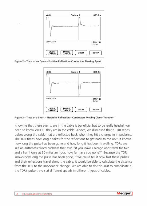
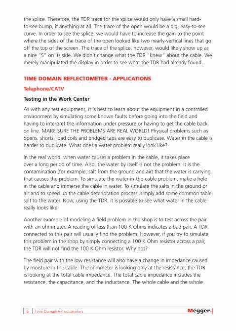
As shown in Figure 2, the reflections are translated by the TDR to traces which can be interpreted to indicate that certain “events” such as opens, shorts, splices, etc. are in the cable. But all traces follow these two basic rules stated above and are displayed on a TDR as shown in Figures 2 and 3.
2 Time Domain Reflectometers
Figure 2 – Trace of an Open – Positive Reflection- Conductors Moving Apart
Figure 3 – Trace of a Short – Negative Reflection – Conductors Moving Closer Together
Knowing that these events are in the cable is beneficial but to be really helpful, we need to know WHERE they are in the cable. Above, we discussed that a TDR sends pulses along the cable that are reflected back when they hit a change in impedance. The TDR times how long it takes for the reflections to get back to the unit. It knows how long the pulse has been gone and how long it has been travelling. TDRs are like an arithmetic word problem that asks “if you leave Chicago and travel for two and a half hours at 50 miles an hour, how far have you gone?” Because the TDR knows how long the pulse has been gone, if we could tell it how fast these pulses and their reflections travel along the cable, it would be able to calculate the distance from the TDR to the impedance change. We are able to do this. But to complicate it, the TDR’s pulse travels at different speeds in different types of cables.
VOP=0.670Cursor519.1 ft
893 ft>Gain = 0<0 ft
LESSCABLE
MORECABLE
ZOOM SETUP
VOP=0.670Cursor519.1 ft
893 ft>Gain = 0<0 ft
LESSCABLE
MORECABLE
ZOOM SETUP

www.megger.com Time Domain Reflectometers 3
Fortunately we can tell the TDR how fast the pulses and their reflections travel in various cables. This speed is usually stated as a ratio of the speed of the pulse in the cable divided by the speed of light in a vacuum. This ratio is called the Velocity of Propagation (VoP). If the VoP is 0.80, the speed of the pulse is 80% of the speed of light in a vacuum or 0.8 x 186,000 miles per second. The manufacturer of the cable states the VoP. Some VoPs by cable type are:
n Communications coax – (with some exceptions) between 0.80 and 0.90
n Twisted pair n 22 gauge filled – 0.66 n 22 gauge air-core – 0.67 n 24 gauge filled – 0.62 n 24 gauge air-core – 0.67
n Coax transmission line – 0.99
If we can see the length markings or measure it to get the length of a section of cable, we can work backwards with a TDR and calculate the VoP. (This gets a bit tricky with twisted pair because the conductors are longer than the cable.)
The TDR now has enough information to calculate where the “event” is. Like our trip from Chicago, it knows how long the pulse and its reflection travelled and it knows how fast that pulse was going. The TDR merely has to do the arithmetic, a LOT of arithmetic.
Does it matter if the event that we are trying to find is very close to the TDR, or far away? It sure does. We can “look” along the entire distance of a very long cable by varying the power, the “width”, of the pulses that the TDR sends out. This is the amount of time that the transmitter is turned on.
We “set” the pulse width. TDRs have varying pulse width settings and modern units, while allowing the operator to vary the pulse width, will automatically set the proper pulse width to best display the first event. The larger the pulse width, the more energy and, therefore, the further the signal will travel on a given cable. A TDR’s distance range is determined by how far the transmitted pulse will travel while still having a detectable reflection returned.

4 Time Domain Reflectometers
Why don’t we just send the most powerful pulse all the time? The width of the transmitted pulse will affect the TDR’s ability to identify reflections. It’s a bit like walking in from the dark and turning on a bright light. The power of the light overpowers our receivers (eyes) and blinds us for a minute. Our eyes adjust by reducing the amount of light that enters our receivers. The TDR’s receivers don’t do this so lower-powered pulses for closer-in events have to be sent. The width of the pulse is sometimes referred to as the dead zone; the distance that the TDR is blind. Figure 4 is a table that relates the typical dead zone at launch to the pulse width in communications coax.
Pulse Width Dead Zone
<1 ns
One billionth
1 foot
2 ns 3 feet
10 ns 14 feet
100 ns 55 feet
1 µs
One millionth
430 feet
2 µs 810 feet
4 µs 1,600 feet
Figure 4 – Pulse Width Dead Zones
We not only have to worry about blind spots at launch (right next to the TDR) but the reflections of events also have blind spots, the size of which are related to the pulse width. The second of two closely-spaced reflections may become masked by the dead zone of the first one.
We’ll consider later what the shape of a trace tells us about an event but for now accept that the signatures displayed in Figure 5 show a twisted pair cable of 3,000 foot length with a splice at 2,000 feet. Signature 1 used a pulse width of 160 ns. Signature 2 used a pulse width of 500 ns and signature 3 used a pulse width of 2 µs. Notice the lengths of the launch dead zones. Also consider the dead zones following the splice. If the splice were a short bridged tap, we wouldn’t see the end of the lateral if we used the 500 ns pulse width.

www.megger.com Time Domain Reflectometers 5
Figure 5 - Pulse Width and Dead Zone
Gain is another variable that we can set that needs consideration. Gain has nothing to do with the physics of what the TDR is doing. Rather, it is a way for us to adjust the trace that the TDR is showing us. It is the degree to which the trace deviates from the horizontal. Remember that a TDR shows us events in a cable that cause the impedance to change at that spot. Consider also that elements that are placed in the cable are meant to exactly match the impedance of that cable so as to minimize the very reflection that the TDR depends on. So, elements such as well-made splices and terminations are, by design, hard for a TDR to see. Modern TDRs adjust the display such that they try to show the trace of the most prominent element. To do this they automatically adjust the gain of the display to nicely show, for example, a major event such as an open. This is all well and good if what we want to see is the open. But, what if we really wanted to see a well-made splice that was somewhere before the open? The impedance mismatch at the open is much more than that at
160 ns
500 ns
2 µs
6 Time Domain Reflectometers
the splice. Therefore, the TDR trace for the splice would only have a small hard-to-see bump, if anything at all. The trace of the open would be a big, easy-to-see curve. In order to see the splice, we would have to increase the gain to the point where the sides of the trace of the open looked like two nearly-vertical lines that go off the top of the screen. The trace of the splice, however, would likely show up as a nice “S” on its side. We didn’t change what the TDR “knew” about the cable. We merely manipulated the display in order to see what the TDR had already found.
TIME DOMAIN REFLECTOMETER - APPLICATIONS
Telephone/CATV
Testing in the Work Center
As with any test equipment, it is best to learn about the equipment in a controlled environment by simulating some known faults before going into the field and having to interpret the information under pressure or having to get the cable back on line. MAKE SURE THE PROBLEMS ARE REAL WORLD! Physical problems such as opens, shorts, load coils and bridged taps are easy to duplicate. Water in the cable is harder to duplicate. What does a water problem really look like?
In the real world, when water causes a problem in the cable, it takes place over a long period of time. Also, the water by itself is not the problem. It is the contamination (for example, salt from the ground and air) that the water is carrying that causes the problem. To simulate the water-in-the-cable problem, make a hole in the cable and immerse the cable in water. To simulate the salts in the ground or air and to speed up the cable deterioration process, simply add some common table salt to the water. Now, using the TDR, it is possible to see what water in the cable really looks like.
Another example of modeling a field problem in the shop is to test across the pair with an ohmmeter. A reading of less than 100 K Ohms indicates a bad pair. A TDR connected to this pair will usually find the problem. However, if you try to simulate this problem in the shop by simply connecting a 100 K Ohm resistor across a pair, the TDR will not find the 100 K Ohm resistor. Why not?
The field pair with the low resistance will also have a change in impedance caused by moisture in the cable. The ohmmeter is looking only at the resistance; the TDR is looking at the total cable impedance. The total cable impedance includes the resistance, the capacitance, and the inductance. The whole cable and the whole

www.megger.com Time Domain Reflectometers 7
fault is included in the impedance. To simulate the fault with just a resistor is not simulating the whole fault. It will not indicate the quality of the cable or how far away the problem is. A TDR will. Therefore, when simulating a field problem in the shop, make certain the whole problem (or model) is simulated.
Moisture in Twisted Pair
Scenario: A rural telephone subscriber complained of a noisy telephone line. The noise is traced to the drop. The subscriber has a 2,800 foot two-pair drop to the home, along a country road ditch, through the yard, and into the house. The unused pair is found to be quieter so the customer is switched to the quieter pair. The problem appears to be solved for now. A few months later, the customer started complaining again!
Basic tests are once again conducted on the pairs and the original pair now appears quieter. This is a common problem experienced when water gets into a cable; noisy pairs going quiet and quiet pairs becoming noisy.
A large percentage of twisted pair problems fall within the moisture-in-the-cable category. How to locate the problem, why one pair may be affected but not another, and how much of the cable is affected are all problems you have to address.
A TDR will find water in the cable. It shows up as a lowering of the cable impedance. Most times though, it is not possible to accurately tell how wide the water problem is. In filled cable, moisture cannot migrate inside the cable so it is always a point problem. In air-core or pulp cable, moisture can migrate anywhere along the cable.
Figure 6: Water in the Cable (example)
8 Time Domain Reflectometers
By testing the cable from both ends and recording the distance to fault in all pairs, it is possible to determine approximately how wide the problem is.
When testing through water, measurements up to the water are very accurate. After the water, distance readings may be erroneous due to a change in the VF (velocity factor) caused by the water. Even though the moisture may be 20 or 30 feet wide, each pair usually becomes impregnated at different points. The range of these points will indicate the length of the problem.
Water can seep into the conductors through pin holes in the plastic insulator around the conductors. Water in a multi-paired, air-core cable may be several feet wide. When testing each pair, the footage to the problem may read different for each pair. This is because the water has penetrated through the conductor insulation at different points and shorted out the conductors at different footages.
After performing TDR tests on the pairs, the location and how wide the water damage ranges are now known. But it is still necessary to locate where the water actually entered the cable. The break in the sheath will not necessarily be within the span of where the water is found and will not necessarily show up in the testing. If the break in the sheath of the cable is not fixed, the problem will show up again in the future.
If the hole in the sheath happens to be at a high point in the cable, the water will enter through the hole then migrate to a lower point. If the water entry point is not found, it may be necessary to visually inspect the cable. It is also necessary to check the integrity of the sheath.
Locating Bridged Taps
A bridged tap is a component within a telephone system that can be one of the easiest things to locate with a TDR. It can also be one of the most incorrectly identified components.
The definition of a bridged tap itself can often cause confusion. Some people refer to a bridged tap as the lateral which extends off of a main cable circuit. However, the true definition of a bridged tap is the point on the cable where a lateral connects to the main cable.
www.megger.com Time Domain Reflectometers 9
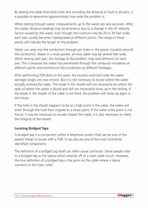
A bridged tap is not a section of cable. Therefore, we will refer to the point of connection of the lateral to the main cable as the bridged tap. The cable extending from the bridged tap to the subscriber will be referred to as the lateral.
A B C D
Figure 7: Bridged Tap (example)
Figure 7 is a common waveform which results from testing a section of cable containing a bridged tap from which a lateral extends to the subscriber.
Referring to Figure 7, a person reviewing the waveform might assume the following:
Point A: The TDR’s pulse from the point of connection.
Point B: (downward reflection) The point of a bridged tap on the main cable.
Point C: The end of the lateral.
Point D: The end of the main cable circuit.
However, Figure 7 could also be the result of a somewhat different cable layout as explained below. A common mistake that is made when testing through bridged taps is to incorrectly identify the end of the lateral for the end of the main cable circuit.
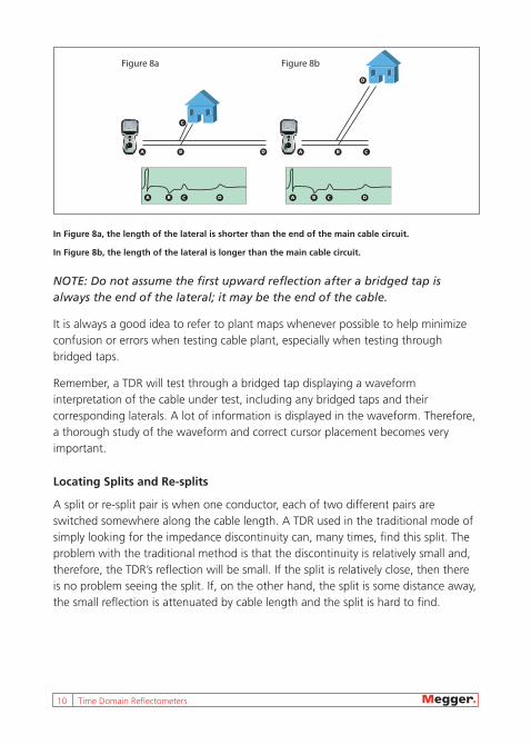
Figures 8a and 8b show two slightly different cable plant layouts. However, notice that the resulting waveforms are identical.
10 Time Domain Reflectometers
A A BB
C
CD
D
A B C D A B C D
Figure 8a Figure 8b
In Figure 8a, the length of the lateral is shorter than the end of the main cable circuit.
In Figure 8b, the length of the lateral is longer than the main cable circuit.
NOTE: Do not assume the first upward reflection after a bridged tap is always the end of the lateral; it may be the end of the cable.
It is always a good idea to refer to plant maps whenever possible to help minimize confusion or errors when testing cable plant, especially when testing through bridged taps.
Remember, a TDR will test through a bridged tap displaying a waveform interpretation of the cable under test, including any bridged taps and their corresponding laterals. A lot of information is displayed in the waveform. Therefore, a thorough study of the waveform and correct cursor placement becomes very important.
Locating Splits and Re-splits
A split or re-split pair is when one conductor, each of two different pairs are switched somewhere along the cable length. A TDR used in the traditional mode of simply looking for the impedance discontinuity can, many times, find this split. The problem with the traditional method is that the discontinuity is relatively small and, therefore, the TDR’s reflection will be small. If the split is relatively close, then there is no problem seeing the split. If, on the other hand, the split is some distance away, the small reflection is attenuated by cable length and the split is hard to find.

www.megger.com Time Domain Reflectometers 11
A B
A B
A B
A B
Figure 9: Split Followed by Re-split (traditional mode)
Using the Model CFL535F in the XTALK mode greatly enhances the reflection and makes finding splits that are far away much easier.
Figure 10 is an example of a split, and split/re-split and their corresponding TDR waveforms using the XTALK mode.
A
A B
B
Figure 10: Split Followed by Re-split (XTALK mode)
Upgrading Cable Plants for xDSL
There are two components found in outside plant that can affect service while upgrading for digital circuits such as xDSL. These components are bridged taps (or laterals), and load coils. Removing bridged taps and load coils is necessary for upgrading, so finding them becomes a challenge.

12 Time Domain Reflectometers
It may be difficult to identify the open at the end of the lateral, but you shouldn’t need to know where the end of the lateral is, only where the bridged tap is. The end of the cable may not be clearly defined because some of the TDR’s pulse energy will be lost going through the tap and lateral.
A bridged tap on a TDR will look similar to a short or downward reflection. Keep in mind that the TDR does not distinguish between the lateral and the continuing length of cable. After finding and removing a lateral, make sure you retest the cable for any laterals that may have been missed.
Locating and Removing Load Coils
Next, find all of the load coils in the system because loaded analog systems and digital systems such as xDSL are not compatible. Distinguishing a load coil from what appears to be an open at the end of the cable may not be easy unless you know exactly what you’re looking for.
There are two basic rules in identifying a load coil from an open. First, a load coil generally displays a more rounded appearance than an open. Second, load coil spacing is very particular; at 3,000 feet (914 m) or 6,000 feet (1829 m) intervals, depending on the location in the section. While not all load coils look the same, if you see an open-like reflection on the waveform at approximately 6,000 feet (1829 m) from the TDR, suspect a load coil. Remember that because the TDR’s signal cannot pass through a load coil, the first load coil is all that you will see. Once you have found the first, remove it and retest the cable.
Finding Repeat Troubles
A major problem in troubleshooting outside plant is locating intermittent faults. The first indication of an intermittent fault is when a telephone customer complains of noisy static or no dial tone or a cable customer complains of snowy reception, which is an intermittent signal. The problem is usually a high resistance series fault or intermittent connectors.
One of the more frustrating troubles found in outside plant today is noisy static. Many times, the customer calls with complaints of sizzling on the line. However, by the time the trouble ticket is received, there is no trouble found. This is because many times, these types of troubles come and go as do the loop current on line. When there is no loop current, the fault heals itself. As soon as you leave the trouble, and the customer uses the line again, they report the same type of trouble again.

www.megger.com Time Domain Reflectometers 13
Solid cases of trouble are very easy to locate with the help of a TDR. If the trouble comes and goes, the technician will have a difficult time getting a distance reading with a TDR. This is very difficult with intermittent faults and repeat-type trouble. When this type of trouble is located very close to the subscriber end of the line, the trouble is usually a high resistance open (series resistance fault).
To locate noisy static troubles quickly and easily with the CFL535F, do the following:
1. Disconnect at the protector on the subscriber end.
2. Confirm the trouble. Connect a butt set, turn the speaker on and listen to the line. Confirm that the trouble you hear (if any) is what the customer reported, and not a separate case of trouble.
3. Turn the butt set to mute, and dial the silent termination. This is done to prevent any noise picked up by the microphone of the butt set being put on the line. It may affect the TDR waveform.
4. Connect the CFL535F. Connect the test probe leads to the pair under test. Continue to keep the butt set connected to the pair with the silent termination.
5. Switch on the TDR by touching the POWER key.
6. Initiate the intermittent fault locate mode.
7. Wait for the fault to occur. With the loop current on line, the trouble will normally appear within 5 to 10 minutes.
Cellular
The TDR can be a very useful tool when turning-up a new cell site. Within a single cell there may be as many as six antenna cables with multiple transmit antenna cables and multiple receive antenna cables.
During installation, it is possible that the cables can become mixed up. Installers are usually more intent on safely making all the right mechanical connections, rather than making sure the cables are connected to the proper antennas. On the other hand, the site operator is very interested in the accuracy of matching cables to antennas.
14 Time Domain Reflectometers
Graphic style TDRs can easily distinguish between receive antenna cables and transmit antenna cables. With the noise filter turned off, connect the TDR to the transmission cable with an antenna in place, zoom in and study the waveform. A very noisy waveform will be seen. The RF signal from the antenna will show up on the TDR baseline as noise. A relatively high gain antenna, such as the receive antenna, will have more signal amplitude than a relatively low gain transmit antenna. This difference in amplitude allows distinction between receive antennas and transmit antennas and makes sure they are not mislabeled and swapped.
If it is necessary to see the actual waveform of the cable under test, even with the antenna connected, simply turn the instrument on and activate the TDR’s noise filter. It will remove most of the RF signal even in a relatively high RF energy level environment.
Electric
Track Down Illegal Electrical Taps
Illegal taps are a huge problem for many electric companies throughout the world because millions of dollars are lost due to theft of service. An illegal tap occurs when an individual connects to the power cable before it reaches the meter. When a customer connects before the meter, they bypass the meter that measures power consumption. In the United States, and other similar networks, power is distributed using high voltage lines to the neighborhood. The high voltage is reduced by a step down transformer near the customer’s home. The smaller low voltage is the 110 Volts that runs most of our appliances. In most cases homes receive two phases of 110 Volts in order to power larger appliances that run on 220 Volts. These two phases are run with a neutral. Normally, the drop line will run directly from the transformer to the house. However, the power company may run a feeder cable of 110 Volts to connect a strip of houses or businesses. Either way, the cable runs to a meter box that registers power usage for the billing process. After the meter, the cable runs to a breaker box and then is distributed throughout the subscriber’s home or office.
When looking for an illegal tap, focus should be placed on the drop line from the meter to the transformer. In the case of aerial cables, focus only on the section of cable that is not visible. This may be the cable inside the conduit, which can be 4-12 feet (1-4 meters) of cable. In the case of buried cable, lengths are often much longer; however, the focus is still on the cable running between the meter and

www.megger.com Time Domain Reflectometers 15
the manhole. To steal power, the customer only needs to tap one phase and use the neutral already in the house. However many connect to both, if not all three phases. Theft of service often occurs at the meter. In this case it is necessary to pull the meter in order to gain access to the cables. Power to the customers will be disconnected when the meter is removed; however, the lines being tested are still live. Testing should be done as quickly as possible, to restore power to the customer. Connect the TDR test leads to the phases, using the CFL535F. It is equipped with an internal voltage blocking filter to protect the operator and instrument. Always connect to the phases first because these are the cables that the customer would tap to steal power. Next, test between the neutral on each of the phases. By testing all the cables, one may discover a difference in waveforms that could prove to be a tap. It is important to save each test for comparison analysis. The stored waveform can then be used to document whether or not a tap was discovered.
Documentation of a tap is also important because of possible legal problems between the customer and the power company. If done incorrectly, testing live power cable can be dangerous.
Low Voltage Networks
In many countries, the 220 VAC residential power distribution system consists of a central local substation transformer which distributes power via three phase cables. A service connection is hard wired into the feed cable as a tee joint which is fed to each consumer. The number of consumers supplied from a particular substation depends on system design and could be as few as ten and as many as several hundred.
To apply the TDR to the low voltage network, the user must be aware of the network they are testing. The tee joints on this type of power network increase the complexity of the waveform trace. The service connection tee joints reflect and split the TDR pulse. The net effect is a complex TDR waveform trace and attenuation that reduces the testable length. The TDR can be useful on the low voltage network, but the user must be wary.
Isolating a fault to a section or particular run of cable will prove valuable by allowing the operator to get closer to the fault. Although the TDR traces produced by the low voltage network are complex, a short or open circuit can be easily visible if the TDR is connected close to the fault. Be aware of how the fault manifests itself and make logical conclusions based on this information. If a group of customers

16 Time Domain Reflectometers
are off-supply after a certain point, it suggests a break in the cable. Testing from a point close to the break will yield better results because of the potential for a more conclusive trace.
The best methods for fault locating on a complex network involve a “before and after” or “good vs. bad” comparison. A healthy TDR trace produced by the complex network shows many reflections caused by the service connection taps and the ends of these cables. Even a gross fault down the network will be masked by the other features of the network. In many cases, comparison and differential techniques are the only option.
Figure 11: Before and After Comparisons
A good practice is to store a TDR waveform trace at the beginning of the troubleshooting process for a particular fault. This creates a reference to compare subsequent traces after the fault has been modified by actions such as replacing fuses, high potential testing, or burning techniques. Once the fault has changed characteristics, before and after traces are compared either by displaying both traces simultaneously on screen or in a difference mode. The point of significant difference on the trace is most likely the fault location.
Although not quite as definitive as a before and after trace in which the fault has changed because of an action, comparison to a good phase can also indicate a fault location. Again, the process is to store a good trace of another phase in the cable as a reference in order to compare the faulty trace.

www.megger.com Time Domain Reflectometers 17
RED
BLUE
YELLOW
Figure 12: Good versus Bad Comparison
Figure 12 shows an example of where an open circuit fault is located on the yellow phase. The blue phase is chosen arbitrarily as common. A TDR trace is stored between the red and blue phases (good) and compared to a TDR trace between the blue and yellow phase (bad). A point of significant difference is most likely the fault location. With this procedure, keep in mind the two traces will not necessarily be identical as will be the case with a before and after test of the same cable. Differences in service connection joint locations and lengths may add minor different features on the TDR trace which are not the fault.
Other TDR Applications
Mining
Because of the risk of explosion, most countries do not allow TDRs down mines. However, as the mine deepens, shafts are dug from the surface and umbilical cables are dropped down. These cables carry power for the tools and telecommunication needs. Due to the distances involved, these cables, especially those used for telecommunications, become stretched and are likely to fail. Simple numeric or graphical TDRs are used to test cable integrity and locate failures such as opens and shorts.

18 Time Domain Reflectometers
Railroad
Various railway systems use twisted pair cables to operate cross arms and light signals. A TDR and cable locator can help sectionalize a fault within these cables and greatly reduce troubleshooting time. Pinpointing a broken or pinched cable in a fraction of the time it would normally take saves time, money, and possibly lives.
Another unique application with railroads is to locate disconnects between railcars. Railcar sections can consist of 100 or more cars. Finding a loose connection with a TDR can save time and money by helping to determine an approximate distance to an open (faulted) cable, versus the traditional method of manually inspecting each connection between cars.
Outside Broadcasting
Outside broadcast vehicles carry an enormous amount of cables depending on the situation; e.g., sporting events can use ten or more different camera locations. Due to the temporary nature of the installation, cables get damaged and TDRs are extensively used to quickly find the faults as they can work on all different types of cable without re-calibration; i.e., from power cables to coax to twisted pair, all of which are in use in an outside broadcast. In outside broadcasting, the camera cables in particular, usually triax construction, are vulnerable. On large sites, e.g. race tracks and golf courses, many drums of cable will be linked together to reach some of the cameras.
Urban Heating and Cooling
Some countries run pipes to their buildings which run hot water in the winter to heat the building. Within the insulation material of the pipe is a pair of wires. If water leaks from the pipe, it will soak the wires and change their impedance. The TDR will detect the impedance change and thus aid in pinpointing the water leak.
www.megger.com Time Domain Reflectometers 19
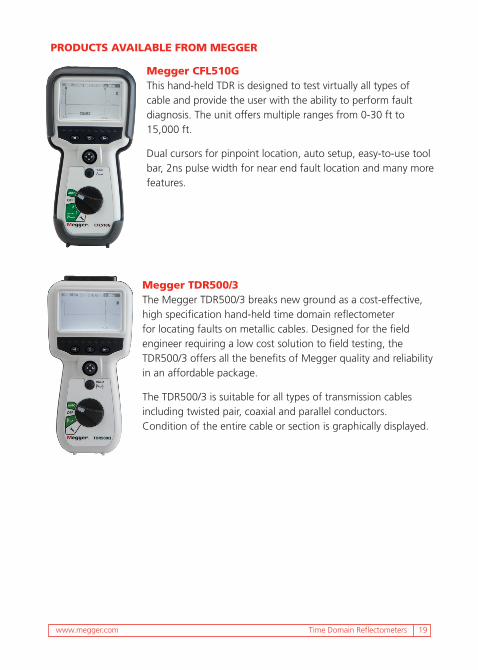
PRODUCTS AVAILABLE FROM MEGGER
Megger CFL510GThis hand-held TDR is designed to test virtually all types of cable and provide the user with the ability to perform fault diagnosis. The unit offers multiple ranges from 0-30 ft to 15,000 ft.
Dual cursors for pinpoint location, auto setup, easy-to-use tool bar, 2ns pulse width for near end fault location and many more features.
Megger TDR500/3The Megger TDR500/3 breaks new ground as a cost-effective, high specification hand-held time domain reflectometer for locating faults on metallic cables. Designed for the field engineer requiring a low cost solution to field testing, the TDR500/3 offers all the benefits of Megger quality and reliability in an affordable package.
The TDR500/3 is suitable for all types of transmission cables including twisted pair, coaxial and parallel conductors. Condition of the entire cable or section is graphically displayed.
20 Time Domain Reflectometers
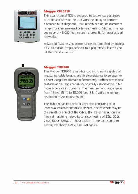
Megger CFL535FThis dual-channel TDR is designed to test virtually all types of cable and provide the user with the ability to perform advanced fault diagnosis. The unit offers nine measurement ranges for ideal near-end or far-end testing. Maximum range coverage of 48,000 feet makes it a great fit for practically all networks.
Advanced features and performance are simplified by adding an auto-cursor. Simply connect to a pair, press a button and let the TDR do the rest.
Megger TDR900The Megger TDR900 is an advanced instrument capable of measuring cable lengths and finding distance to an open or a short using time domain reflectometry. It offers exceptional features and a range capability normally associated with far more expensive instruments. The measurement range spans from 15 feet (5 m) to 10,000 feet (3 km) with a minimum resolution of 20 inches (50 cm).
The TDR900 can be used for any cable consisting of at least two insulated metallic elements, one of which may be the sheath or shield of the cable. The meter has automatic internal matching networks to allow testing of 25Ω, 50Ω, 75Ω, 100Ω, 125Ω, or 150Ω cables. (These correspond to power, telephony, CATV, and LAN cables.)


Megger is your source for testing needsMegger offers the following high-quality instruments for testing
telecommunication systems.
n Time Domain Reflectometers n Insulation Resistance Test Equipment
n Battery Test Equipment n Multimeters/Clampmeters
n Ground Resistance Test Equipment n Time Domain Reflectometers
n Low Resistance Ohmmeters
Visit our website for additional information at www.megger.com.
UNITED STATES 2621 Van Buren Avenue Norristown, PA 19403 Phone: 866-254-0962 Phone: 610-676-8500 Fax: 610-676-8610
TDR_AG_en_V01
OTHER TECHNICAL SALES OFFICESDallas USA, College Station USA, Sydney AUSTRALIA, Täby SWEDEN, Ontario CANADA, Trappes FRANCE, Oberursel GERMANY, Aargau SWITZERLAND, Dubai UAE, Mumbai INDIA, Johannesburg SOUTH AFRICA, and Chonburi THAILAND


