15
DOE/SC-ARM-TR-256 Time-Resolved Aerosol Filter Sampler Instrument Handbook November 2020 F Mei L Goldberger
DOE/SC-ARM-TR-256
Time-Resolved Aerosol Filter Sampler Instrument Handbook
November 2020
F Mei L Goldberger

DISCLAIMER
This report was prepared as an account of work sponsored by the U.S. Government. Neither the United States nor any agency thereof, nor any of their employees, makes any warranty, express or implied, or assumes any legal liability or responsibility for the accuracy, completeness, or usefulness of any information, apparatus, product, or process disclosed, or represents that its use would not infringe privately owned rights. Reference herein to any specific commercial product, process, or service by trade name, trademark, manufacturer, or otherwise, does not necessarily constitute or imply its endorsement, recommendation, or favoring by the U.S. Government or any agency thereof. The views and opinions of authors expressed herein do not necessarily state or reflect those of the U.S. Government or any agency thereof.

DOE/SC-ARM-TR-256
Time-Resolved Aerosol Filter Sampler Instrument Handbook F Mei L Goldberger Both at Pacific Northwest National Laboratory November 2020 Work supported by the U.S. Department of Energy, Office of Science, Office of Biological and Environmental Research

F Mei and L Goldberger, November 2020, DOE/SC-ARM-TR-256
iii
Acronyms and Abbreviations
AAF ARM Aerial Facility ACCESS aerosol counting, composition, extinction, and sizing system ADC ARM Data Center AMS aerosol mass spectrometer ARM Atmospheric Radiation Measurement ASCII American Standard Code for Information Interchange CPC condensation particle counter MCPC mixing condensation particle counter MIST multiple instrument stackable tower MOPC mixing condensation particle counter netCDF Network Common Data Form PC personal computer STAP single-channel tricolor absorption photometer UAS unmanned aerial system UAV unmanned aerial vehicle UTC Coordinated Universal Time VDC volts direct current

F Mei and L Goldberger, November 2020, DOE/SC-ARM-TR-256
iv
Contents
Acronyms and Abbreviations ...................................................................................................................... iii 1.0 Instrument Title .................................................................................................................................... 1 2.0 Mentor Contact Information ................................................................................................................. 1 3.0 Vendor/Developer Contact Information ............................................................................................... 1 4.0 Instrument Description ......................................................................................................................... 1 5.0 Measurements Taken ............................................................................................................................ 1 6.0 Links to Definitions and Relevant Information .................................................................................... 2
6.1 Data Object Description ............................................................................................................... 2 6.2 Data Ordering ............................................................................................................................... 2 6.3 Data Plots ..................................................................................................................................... 3 6.4 Data Quality ................................................................................................................................. 3 6.5 Calibration Database .................................................................................................................... 4
7.0 Technical Specification ........................................................................................................................ 5 7.1 Input Values ................................................................................................................................. 5 7.2 Output Values ............................................................................................................................... 5
8.0 Instrument System Functional Diagram ............................................................................................... 6 9.0 Instrument/Measurement Theory.......................................................................................................... 6 10.0 Setup and Operation of Instrument ....................................................................................................... 6 11.0 Software ................................................................................................................................................ 7 12.0 Calibration ............................................................................................................................................ 7 13.0 Maintenance.......................................................................................................................................... 8 14.0 Safety .................................................................................................................................................... 8 15.0 Citable References ................................................................................................................................ 8
Figures
1 The chemical filter’s housekeeping data during a laboratory bench test. ............................................... 3 2 Context for the chemical sampler. .......................................................................................................... 4 3 Ambient aerosol chemical information collected by the filter sampler during a wildfire event on
8/14/18. ................................................................................................................................................... 4 4 Image of aerosol chemical filter sampler from the manufacturer’s website........................................... 6 5 MIST instrument payload tower. ............................................................................................................ 7 6 ArcticShark with nose inlet installed. ..................................................................................................... 7

F Mei and L Goldberger, November 2020, DOE/SC-ARM-TR-256
v
Tables
1 Data file column definitions. .................................................................................................................. 2 2 Filter sampler specification parameters. ................................................................................................. 5
F Mei and L Goldberger, November 2020, DOE/SC-ARM-TR-256
1
1.0 Instrument Title The U.S. Department of Energy Atmospheric Radiation Measurement (ARM) user facility’s aerosol counting, composition, extinction, and sizing system (ACCESS) includes a base module (9400), a filter sampler (9401), an advanced mixing condensation particle counter (MCPC, 9403), a miniaturized optical particle counter (MOPC, 9405), and a single-channel tricolor absorption photometer (STAP, 9406).
This handbook describes the principles and operations of the filter sampler.
2.0 Mentor Contact Information Fan Mei Pacific Northwest National Laboratory 902 Battelle Boulevard P.O. Box 999, MSIN K4-28 Richland, Washington 99352 Tel: 509-375-3965 [email protected]
3.0 Vendor/Developer Contact Information Fred Brechtel 1789 Addison Way Hayward, California 94544 Tel: 510-732-9723 https://www.brechtel.com
4.0 Instrument Description The miniaturized eight-channel filter sampler for time-resolved aerosol chemistry measurements is part of the ACCESS payload, ideal for deployment on unmanned aerial vehicles (UAVs) due to its small size, portability, low weight, and low power usage. The filter sampler is controlled by the base module, a ruggedized tablet PC with user interface software preinstalled. The sampler itself is an eight-channel filter sampler (Model 9401 FILT) for offline chemical composition measurements.
5.0 Measurements Taken The Model 9401 sampler performs time-resolved filter sampling to acquire aerosol samples from UAV with remote control capability. With eight filter channels, multiple samples can be obtained with the time resolution tailored to the aerosol loading. The samples collected are then analyzed offline once the collection is complete.
F Mei and L Goldberger, November 2020, DOE/SC-ARM-TR-256
2
6.0 Links to Definitions and Relevant Information Product website: https://www.brechtel.com/products-item/filter-sampler/
Instrument webpage from arm.gov: https://www.arm.gov/capabilities/instruments/filteraerosol-air
6.1 Data Object Description
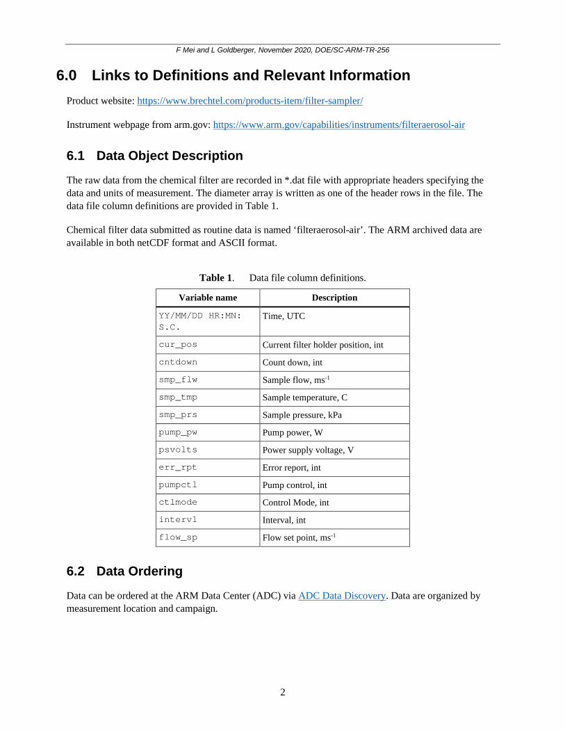
The raw data from the chemical filter are recorded in *.dat file with appropriate headers specifying the data and units of measurement. The diameter array is written as one of the header rows in the file. The data file column definitions are provided in Table 1.
Chemical filter data submitted as routine data is named ‘filteraerosol-air’. The ARM archived data are available in both netCDF format and ASCII format.
Table 1. Data file column definitions.
Variable name Description
YY/MM/DD HR:MN: S.C.
Time, UTC
cur_pos Current filter holder position, int
cntdown Count down, int
smp_flw Sample flow, ms-1
smp_tmp Sample temperature, C
smp_prs Sample pressure, kPa
pump_pw Pump power, W
psvolts Power supply voltage, V
err_rpt Error report, int
pumpctl Pump control, int
ctlmode Control Mode, int
intervl Interval, int
flow_sp Flow set point, ms-1
6.2 Data Ordering
Data can be ordered at the ARM Data Center (ADC) via ADC Data Discovery. Data are organized by measurement location and campaign.

F Mei and L Goldberger, November 2020, DOE/SC-ARM-TR-256
3
6.3 Data Plots
The Brechtel software records housekeeping data from the chemical filter. The filters are analyzed offline. Figure 1 shows the housekeeping plots that the ARM Aerial Facility (AAF) field crew use to check the instrument health during flight operation.
Figure 1. The chemical filter’s housekeeping data during a laboratory bench test.
6.4 Data Quality
The ACCESS suite of instrumentation was tested in the laboratory during a wildfire event on 4 August 2018. An inlet connected the ACCESS suite to the ambient air 10 m above the ground. Figure 2 shows the total number concentration observed by two condensation particle counters. One is a water-based particle counter (Magic CPC), and the other one also belongs to the ACCESS suite, which is an advanced mixing CPC. The difference between the two CPCs was less than 20% during this sampling period. The filter samples collected simultaneously were analyzed using a unique extraction-aided aerosol mass spectrometer(AMS). Dr. Zhang’s group operated this AMS from the University of California, Davis, https://etox.ucdavis.edu/zhang-qi. As shown in Figure 3, aerosol particles collected were primarily made of organic matters. The analysis information can be found in http://www.asrc.cestm.albany.edu/qz/AMS%20organic%20data%20and%20analysis.pdf.

F Mei and L Goldberger, November 2020, DOE/SC-ARM-TR-256
4
Figure 2. Context for the chemical sampler. Ambient aerosol measured by Magic condensation particle counter (CPC) and the ACCESS mixing CPC during a wildfire event on 8/14/2018. Top: total aerosol number concentration recorded both by the ACCESS mixing CPC and a Magic CPC. Bottom: an agreement between the CPCs.
Figure 3. Ambient aerosol chemical information collected by the filter sampler during a wildfire event on 8/14/18.
6.5 Calibration Database
The instrument mentors periodically verify the filter sampler calibration.
08/15-00:00 03:00
UTC time
0
2000
4000
6000
8000
Tota
l num
ber c
once
ntra
tion,
cm
-3
Magic CPC
Mixing CPC
21:30 22:00 22:30 23:00 23:30 08/15-00:00 00:30 01:00 01:30 02:00 02:30 03:00 03:30
UTC time
1
1.1
1.2
1.3
1.4
1.5
NM
agic
CPC
/NC
PC
96%
1%1%2%0%
10
8
6
4
2
0
% o
f tot
al
150140130120110100908070605040302010m/z (amu)
O/C = 0.50, H/C = 1.33, N/C = 0.028, OM/OC = 1.81
CxHy C
xHyO1 CxHyO2
HyO1
CxHyNpCxHyOzNp C
xHyOzSq
UAS7d_HROrg

F Mei and L Goldberger, November 2020, DOE/SC-ARM-TR-256
5
7.0 Technical Specification
Table 2. Filter sampler specification parameters.
PARAMETER VALUE
Number of filter channels 8
Filter type Teflon, 1 μm pore
Filter size 13 mm diameter
Sample flow 0.1-3 lpm
Size: Main body 3"dia x 3.5" high/7.6 x 8.9 cm
Size: Pump assembly 3.5 x 2.3 x 2.5 in/8.9 x 5.8 x 6.6 cm
Weight 1.5 lbs/0.7 kg
Supply voltage 12 VDC
Power 10 watts
The filters or substrates will be analyzed offline, and the offline analysis determines the data accuracy.
7.1 Input Values
Depending on the flight plan, this filter sampler can run with the “manual” mode or “auto” mode. Under manual mode, the user will need to input the sampling spot location and duration. Under auto mode, the sampler will sample through each spot based on the set duration.
7.2 Output Values
Filter position – sample flow – temperature – pressure – error report

F Mei and L Goldberger, November 2020, DOE/SC-ARM-TR-256
6
8.0 Instrument System Functional Diagram
Figure 4. Image of aerosol chemical filter sampler from the manufacturer’s website.
9.0 Instrument/Measurement Theory The aerosol chemical filter sampler draws air from a universal inlet over a single filter installed in one of eight of its filter holders. The aerosol and sticky gases are trapped on the Teflon filter, while the remaining gases are exhausted out a port on the other side. After a preprogrammed time, the filter holders rotate, and aerosol is collected onto a new filter. Accounting for filter cross-sectional area, sample flow rate, and time, the air volume collected onto the filter is calculated.
The filters can be analyzed offline in several ways. The aerosol and sticky gases collected from the filter can be extracted into a solution and characterized using aerosol mass spectroscopy for chemical information.
10.0 Setup and Operation of Instrument Deployment on a TigerShark or ArcticShark unmanned aerial system (UAS)
The ACCESS aerosol chemistry filter is installed on the multiple instrument stackable tower (MIST) in the main payload bay of the ArcticShark UAS. The MIST itself is seated in the payload bay connected by four vibration isolators to reduce noise. Outside air is brought into the payload via a universal inlet installed on the nose of the UAS. The inlet is pumped actively via a scroll pump and controlled with a mass flow controller. The instrument is initialized by an onboard data acquisition system that operates the Brechtel LabVIEW software. The data is transmitted to scientists on the ground in real time.

F Mei and L Goldberger, November 2020, DOE/SC-ARM-TR-256
7
Figure 5. MIST instrument payload tower. Left: on laboratory bench. Right: Schematic with instrument
placement clarified.
Figure 6. ArcticShark with nose inlet installed.
11.0 Software The data acquisition unit on the ArcticShark is installed with the manufacturer’s LabView software.
For further details, consult the manufacturer’s manual.
12.0 Calibration The filter sampler flow needs to be checked weekly during the field study and calibrated at least before and after each field campaign or as needed.

F Mei and L Goldberger, November 2020, DOE/SC-ARM-TR-256
8
13.0 Maintenance The filter holders and connective tubing require periodic cleaning to remove impurities. One maintenance kit is included with the sampler.
14.0 Safety This unit has no safety concerns during regular operation.
15.0 Citable References [1] Filter Sampler Model 9401. https://www.brechtel.com/products-item/filter-sampler/. Accessed 08/25/2020.
[2] Bates, TS, PK Quinn, JE Johnson, A Corless, FJ Brechtel, SE Stalin, C Meinig, and J Burkhart. 2013. “Measurements of atmospheric aerosol vertical distributions above Svalbard, Norway using unmanned aerial systems (UAS).” Atmospheric Measurement Techniques 6(8): 2115−2120, https://doi.org/10.5194/amt-6-2115-2013


![Particle resolved simulation of aerosol size, composition ...nriemer/papers/zaveri_2010.pdf · 2001; Forster et al., 2007]. Among other key advances, the next generation of climate](https://static.documents.pub/doc/80x56/5f26850ce4e447606a0a893f/particle-resolved-simulation-of-aerosol-size-composition-nriemerpaperszaveri2010pdf.jpg)


