41 st Annual Precise Time and Time Interval (PTTI) Meeting 67 TIME TRANSFER BY LASER LINK - T2L2: RESULTS OF THE FIRST YEAR OF OPERATION Philippe Guillemot CNES – French Space Agency, Toulouse, France E-mail: [email protected]Pierre Exertier Observatoire de la Côte d’Azur, Grasse, France Etienne Samain, Francis Pierron, Jean-Marie Torre Observatoire de la Côte d’Azur, Caussol, France Sylvie Leon CNES – French Space Agency, Paris, France Abstract The Time Transfer by Laser Link (T2L2) experiment is a joint CNES and OCA space mission that will perform ground-to-ground time transfer with an expected time stability of about 1 ps over 1,000 s and 10 ps over 1 day and a time accuracy in the 100 ps range. The T2L2 instrument is onboard the Jason-2 satellite launched in June 2008. It has been in operation for 18 months. After a short period devoted to the characterization and the calibration of the system, the mission is in its “operational” phase. First ground-to-space time transfers have demonstrated noise levels of some tens of picoseconds and a preliminary time stability of a few picoseconds over integration times of some tens of seconds, clearly limited by the onboard clock. The 2009 T2L2 experimental program has two major experiences. The first one is a common-clock time transfer between two co-located laser stations MeO and FTLRS. The second is the validation of a distant comparison between cold atoms fountain clocks and RF time transfer systems. This validation is done with 3 regular laser stations (France, Poland, Japan) and also the French transportable laser ranging system (FTLRS) based at Paris (Syrte). The availability on these sites of both a GPS and a TWSTFT station will allow a direct comparison of T2L2 with RF time transfer techniques. After summarizing the principle, the exploitation plan, and the objectives of the mission, the paper will present first results of these experiences and others validations of the T2L2 system. INTRODUCTION Optical time transfer is an evolution of current time transfer systems profiting from advantages of the optical domain as compared to radiofrequency techniques such as higher modulation bandwidth,
Transcript
41st Annual Precise Time and Time Interval (PTTI) Meeting
67
TIME TRANSFER BY LASER LINK - T2L2:
RESULTS OF THE FIRST YEAR OF OPERATION
Philippe Guillemot CNES – French Space Agency, Toulouse, France
Pierre Exertier Observatoire de la Côte d’Azur, Grasse, France
Etienne Samain, Francis Pierron, Jean-Marie Torre
Observatoire de la Côte d’Azur, Caussol, France
Sylvie Leon CNES – French Space Agency, Paris, France
Abstract
The Time Transfer by Laser Link (T2L2) experiment is a joint CNES and OCA space mission that will perform ground-to-ground time transfer with an expected time stability of about 1 ps over 1,000 s and 10 ps over 1 day and a time accuracy in the 100 ps range. The T2L2 instrument is onboard the Jason-2 satellite launched in June 2008. It has been in operation for 18 months. After a short period devoted to the characterization and the calibration of the system, the mission is in its “operational” phase. First ground-to-space time transfers have demonstrated noise levels of some tens of picoseconds and a preliminary time stability of a few picoseconds over integration times of some tens of seconds, clearly limited by the onboard clock.
The 2009 T2L2 experimental program has two major experiences. The first one is a
common-clock time transfer between two co-located laser stations MeO and FTLRS. The second is the validation of a distant comparison between cold atoms fountain clocks and RF time transfer systems. This validation is done with 3 regular laser stations (France, Poland, Japan) and also the French transportable laser ranging system (FTLRS) based at Paris (Syrte). The availability on these sites of both a GPS and a TWSTFT station will allow a direct comparison of T2L2 with RF time transfer techniques.
After summarizing the principle, the exploitation plan, and the objectives of the mission, the
paper will present first results of these experiences and others validations of the T2L2 system.
INTRODUCTION Optical time transfer is an evolution of current time transfer systems profiting from advantages of the optical domain as compared to radiofrequency techniques such as higher modulation bandwidth,
41st Annual Precise Time and Time Interval (PTTI) Meeting
68
insensitivity to ionosphere, and mono-carrier scheme. After its early predecessor LASSO [1], the T2L2 (Time Transfer by Laser Link) instrument [2], developed by CNES (Centre National d'Etudes Spatiales) and OCA (Observatoire de la Côte d'Azur), will prove the concept of time transfer based on a free-space laser link. The principle is derived from Satellite Laser Ranging (SLR) and relies on the propagation of laser pulses between the clocks to be synchronized. T2L2 will provide the capability to compare today’s most stable frequency standards with unprecedented stability and accuracy. Expected T2L2 performances are in the 100 ps range for accuracy, with an ultimate time stability about 1 ps over 1,000 s and 10 ps over 1 day. The objectives of the T2L2 experiment on Jason-2 are threefold:
• Technological validation of optical time transfer, including the validation of the experiment, its time stability, and accuracy and of one-way laser ranging
• Characterization of the onboard Doris oscillator for Jason-2 purposes and a contribution to the
Jason-2 laser ranging core mission • Scientific applications such as time and frequency metrology (comparison of distant clocks,
calibration of RF links), fundamental physics (anisotropy of the speed of light, possible drift of the fine structure constant), earth observation, or very long baseline interferometry (VLBI).
The Jason-2 satellite has been successfully launched on 30 June 2008. The T2L2 instrument has been turned on for the first time a few days later, on 25 June, and is fully operational since that date. Then the second part of 2008 has been devoted to a first functional validation of the T2L2 system, from the on-board instrument up to data processing at the T2L2 Scientific Mission Center (OCA, Grasse). A preliminary evaluation of the performances has also been done [3]. The 2009 T2L2 experimental program shall contribute to the calibration/validation of T2L2 performances through two major experiences. The first one is a common-clock time transfer between two co-located laser stations at the OCA: a fixed one, MeO (Optical Metrology), and the French Transportable Laser Station (FTLRS). The second is a distant comparison (600 km) between two cold atoms fountain clocks. This configuration is made possible by the installation of the FTLRS at SYRTE (Paris) and the installation of the SYRTE mobile fountain FOM on the site of Calern linked to the MeO laser station. The availability, on these two sites, of both a GPS and a TWSTFT station will also allow a direct comparison of T2L2 with RF time transfer techniques. T2L2 PRINCIPLE T2L2 allows the synchronization of remote clocks on Earth and the monitoring of satellite clocks. The experiment is based on the propagation of light pulses between the clocks to be synchronized. The light pulses carry the temporal information from one clock to another. The ground and satellite clocks (the ultra-stable oscillator USO of DORIS in the case of Jason-2) to be synchronized are linked to a laser station and to the T2L2 space equipment, respectively. The T2L2 payload is constituted of a photo-detection device, a time-tagging unit, and a retro-reflector. The laser station emits asynchronous, short light pulses (~ 20 ps FWHM) towards the satellite. Retro-reflecting corner-cubes return a fraction of the received photons back to the station. The station records the start (tS) and return (tR) time of each light pulse. The T2L2 payload records the arrival time (tB) in the temporal reference frame of the onboard oscillator, which is then downloaded to the ground via a regular microwave
41st Annual Precise Time and Time Interval (PTTI) Meeting
69
communication link. The set of these three dates {tS, tB, tR} is called a “triplet.” For a given light pulse emitted from station A, the synchronization TGS[A] between the ground clock A and the satellite clock is then derived from :
GeomSagnacInstrBRS
AGS tttT τττ +++−+
=2][
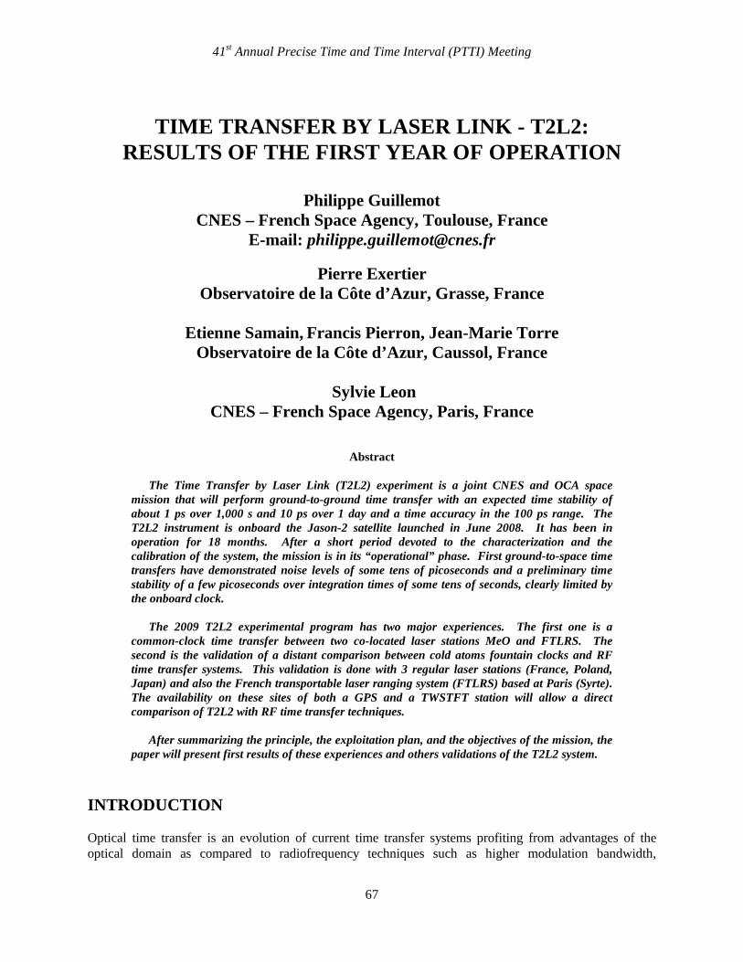
The T2L2 payload, launched in June 2008 together with the Jason-2 space vehicle dedicated to the observation of the oceans, consists of the T2L2 instrument itself, the ultra-stable oscillator of the DORIS receiver as the reference clock, and a laser retro-reflector (LRA – Laser Ranging Array) to reflect the light pulses. The T2L2 instrument is divided in two parts:
• On the one hand, the electronics subsystem, a box of 8 kg with a footprint of 270 mm × 280 mm and a height of 150 mm with a total power consumption of about 42 W, is mounted inside the payload module, on the X+ wall
• And, on the other hand, two optical units for linear and non-linear detection, mounted on an interface plate with an active thermal control and fixed on the LRA boom. Whereas the linear detector is housed inside the linear unit, the nonlinear detector is housed in the electronic unit so that the nonlinear detection unit is linked to the electronic subsystem, thanks to an optic fiber.
Figure 1. T2L2 Flight Model: The electronic unit (left), and optical units together with the LRA (right).
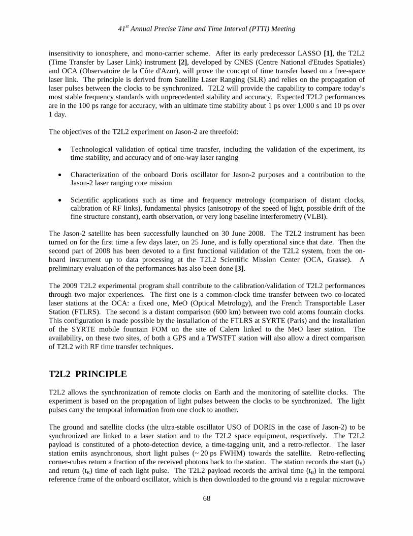
Figure 2 shows the synoptic of the whole T2L2 space instrument. The photo-detection unit is composed of two avalanche photo-detectors. One is working in a special “Geiger” mode for precise chronometry, the other one is in linear gain mode in order to trigger the system and to measure the received optical energy [4-6]. The event timer is a dedicated design, built with a programmable logic array at 100 MHz for rough timing and a vernier for precise measurement with a resolution of 1 ps [7].
41st Annual Precise Time and Time Interval (PTTI) Meeting
70
Figure 2. Synoptic of the whole T2L2 space instrument. The linear photo detection is able to pre-trigger the Geiger module with an advance of a few ns. This delay is generated by an optical delay line connected to the Geiger detection.
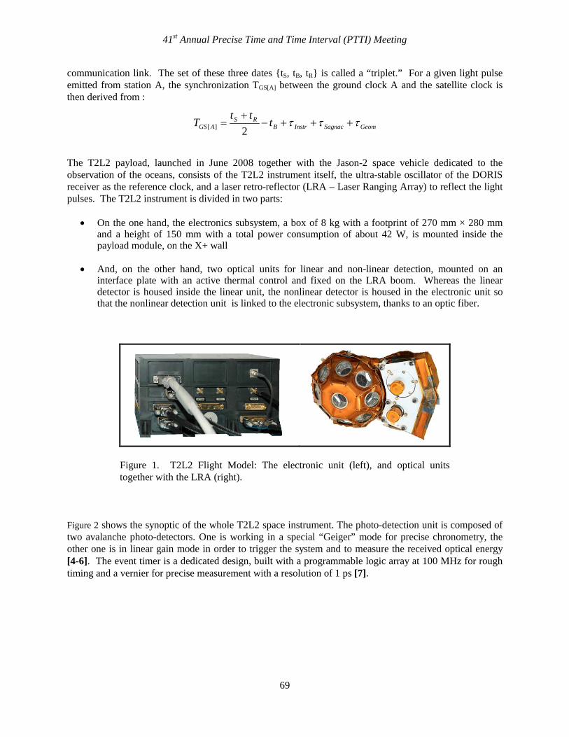
The performances of the T2L2 Flight Model have been determined during two main test campaigns, first before the delivery of the instrument, then during its integration on the Jason-2 space vehicle [8]. The goals of these campaigns were first to determine the true performances of the instrument and second to establish calibration tables in order to elaborate a model of the instrument. At the end, these test campaigns have allowed to confirm the performances of the instrument, over a wide range of operating conditions (single photon or multi photon mode, various angle of incidence of the light, different temperatures, vacuum or atmospheric pressure…). The requirements [Eq. 1] are nearly fulfilled even in the single-photon/worst-case mode (Figure 3): Requirement: 12
212
12 )( +− ×+×≤ τττσ KKx
with spsK 6.121 = and sfsK 6.122 = (Eq.1)
Figure 3. Stability (time variance) of the whole detection/event timer chain in single-photon mode.
41st Annual Precise Time and Time Interval (PTTI) Meeting
71
I. DATA PROCESSING Several steps are necessary to process the data. TRIPLET EXTRACTIONS The events recorded by the T2L2 space instrument don’t contain any information of the source: the events of all the laser stations are blended together. So the first step of the treatment consists of associating the laser events recorded by T2L2 with those emitted by the stations. We have first to synchronize T2L2 local time with UTC. The absolute frequency offset of the local oscillator and the delay between space and ground are known with an accuracy that permits one to directly recognize the events by their dates. The process consists then of comparing, for each laser event, the computed arrival dates, deduced from the departure date and the orbit, with the onboard UTC dates. INSTRUMENTAL CORRECTIONS The instrumental corrections τInstr concern both the space and the ground segments. On the ground, the accuracy is obtained by an internal calibration. During the pass on the satellite (or just before or just after), some events are also acquired on a calibration target located at a known position. The final propagation delay is the difference between the data directly obtained on the satellite and those obtained on reference target. At the satellite several considerations have to be taken into account [8]:
• Geometrical delay between the reference point of the T2L2 detection module and the reference point of the LRA. This is obtained with the attitude information given by the stellar sensors of Jason-2 and the knowledge of the geometry of the space optics.
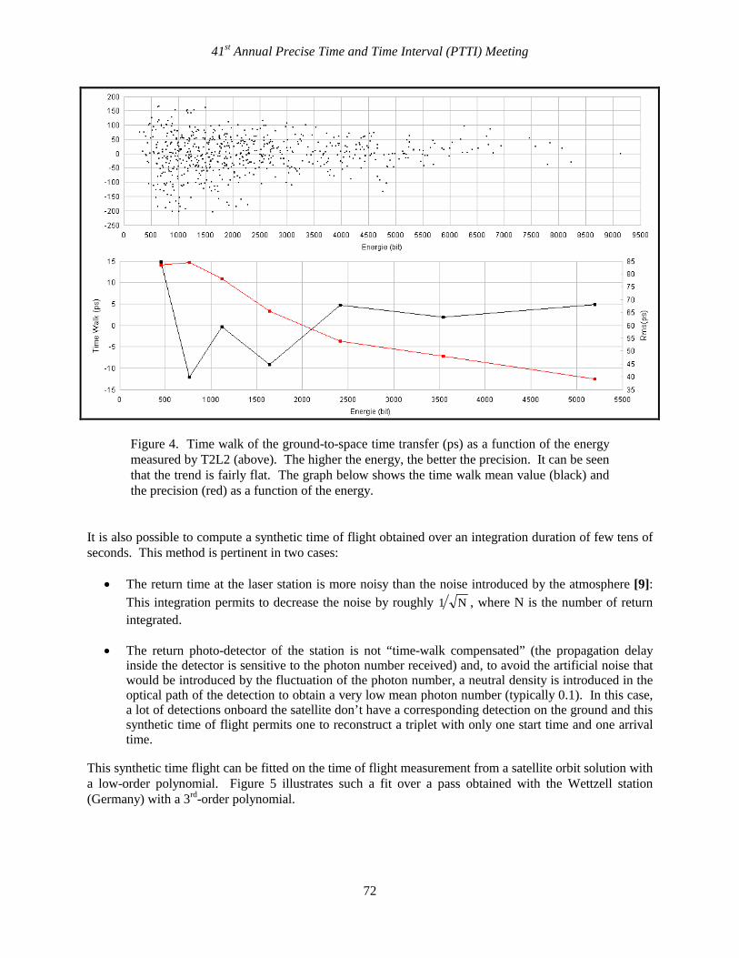
• Time walk compensation of the photo-detection module, which is sensitive to the photon number received (Figure 4). This is done through the information given by the linear photo-detector of the instrument that give, for each event detected, the energy received.
• Angular compensation of the photo-detection. This is also computed from the attitude information. • Event timer calibration based on some internal calibrations automatically generated.
TIME OF FLIGHT DETERMINATION The determination of the time of flight TFlight between the ground and the space segment is, of course, fundamental for the time transfer computation. It permits direct comparison of the start time tS at the station and the arrival time at the satellite of every laser events. This time of flight is based on the difference between the start time and the return time in the frame of the ground station divided by 2 and corrected by the distance between the LRA and the photo-detection module τGeom. At this stage, the time of flight can be directly used echo by echo. If the precision of the measurements is optimal, this process is the best one: The uncertainty of the satellite position and the uncertainty introduced by the atmosphere are removed.
41st Annual Precise Time and Time Interval (PTTI) Meeting
72
Figure 4. Time walk of the ground-to-space time transfer (ps) as a function of the energy measured by T2L2 (above). The higher the energy, the better the precision. It can be seen that the trend is fairly flat. The graph below shows the time walk mean value (black) and the precision (red) as a function of the energy.
It is also possible to compute a synthetic time of flight obtained over an integration duration of few tens of seconds. This method is pertinent in two cases:
• The return time at the laser station is more noisy than the noise introduced by the atmosphere [9]: This integration permits to decrease the noise by roughly N1 , where N is the number of return integrated.
• The return photo-detector of the station is not “time-walk compensated” (the propagation delay inside the detector is sensitive to the photon number received) and, to avoid the artificial noise that would be introduced by the fluctuation of the photon number, a neutral density is introduced in the optical path of the detection to obtain a very low mean photon number (typically 0.1). In this case, a lot of detections onboard the satellite don’t have a corresponding detection on the ground and this synthetic time of flight permits one to reconstruct a triplet with only one start time and one arrival time.
This synthetic time flight can be fitted on the time of flight measurement from a satellite orbit solution with a low-order polynomial. Figure 5 illustrates such a fit over a pass obtained with the Wettzell station (Germany) with a 3rd-order polynomial.
41st Annual Precise Time and Time Interval (PTTI) Meeting
73
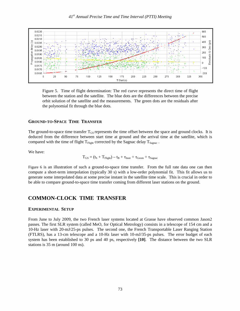
Figure 5. Time of flight determination: The red curve represents the direct time of flight between the station and the satellite. The blue dots are the differences between the precise orbit solution of the satellite and the measurements. The green dots are the residuals after the polynomial fit through the blue dots.
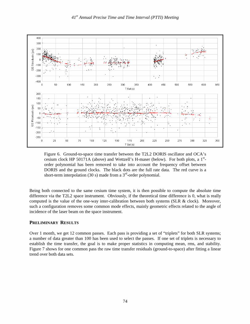
GROUND-TO-SPACE TIME TRANSFER The ground-to-space time transfer TGS represents the time offset between the space and ground clocks. It is deduced from the difference between start time at ground and the arrival time at the satellite, which is compared with the time of flight TFlight corrected by the Sagnac delay TSagnac . We have:
TGS = (tS + TFlight) – tB + τInstr + τGeom + τSagnac Figure 6 is an illustration of such a ground-to-space time transfer. From the full rate data one can then compute a short-term interpolation (typically 30 s) with a low-order polynomial fit. This fit allows us to generate some interpolated data at some precise instant in the satellite time scale. This is crucial in order to be able to compare ground-to-space time transfer coming from different laser stations on the ground. COMMON-CLOCK TIME TRANSFER EXPERIMENTAL SETUP From June to July 2009, the two French laser systems located at Grasse have observed common Jason2 passes. The first SLR system (called MeO, for Optical Metrology) consists in a telescope of 154 cm and a 10-Hz laser with 20-mJ/25-ps pulses. The second one, the French Transportable Laser Ranging Station (FTLRS), has a 13-cm telescope and a 10-Hz laser with 10-mJ/35-ps pulses. The error budget of each system has been established to 30 ps and 40 ps, respectively [10]. The distance between the two SLR stations is 35 m (around 100 ns).
41st Annual Precise Time and Time Interval (PTTI) Meeting
74
Figure 6. Ground-to-space time transfer between the T2L2 DORIS oscillator and OCA’s cesium clock HP 50171A (above) and Wettzell’s H-maser (below). For both plots, a 1st- order polynomial has been removed to take into account the frequency offset between DORIS and the ground clocks. The black dots are the full rate data. The red curve is a short-term interpolation (30 s) made from a 3rd-order polynomial.
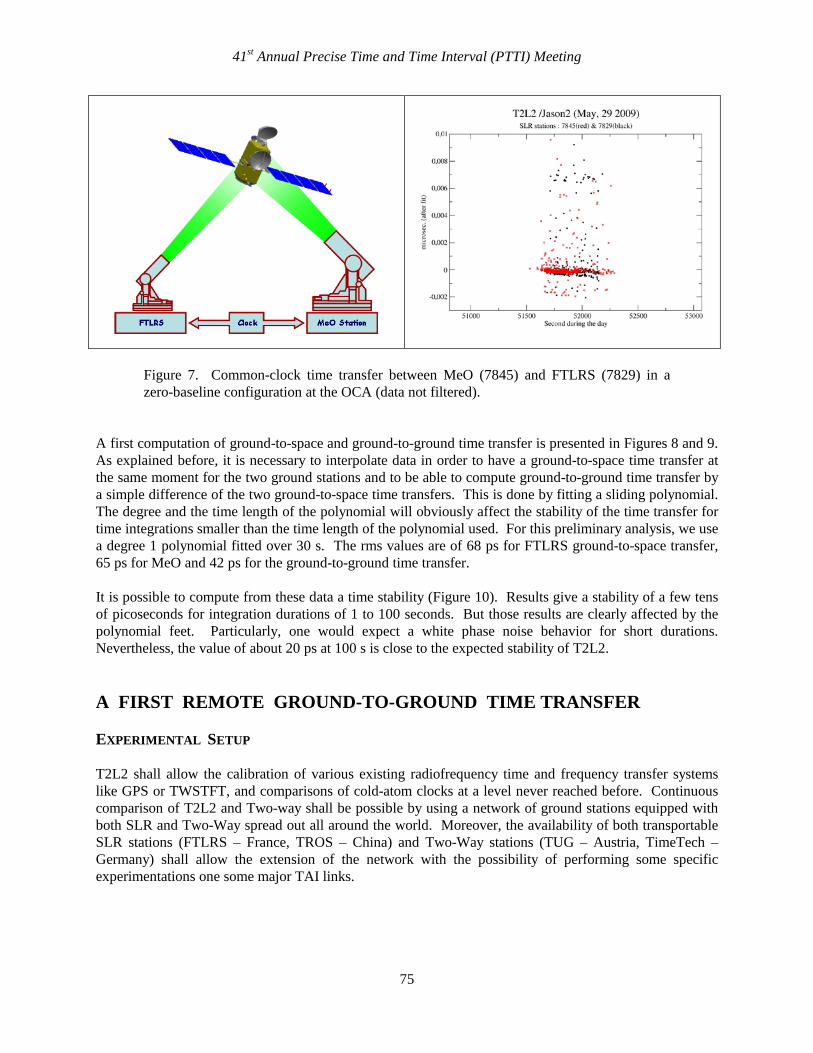
Being both connected to the same cesium time system, it is then possible to compute the absolute time difference via the T2L2 space instrument. Obviously, if the theoretical time difference is 0, what is really computed is the value of the one-way inter-calibration between both systems (SLR & clock). Moreover, such a configuration removes some common mode effects, mainly geometric effects related to the angle of incidence of the laser beam on the space instrument. PRELIMINARY RESULTS Over 1 month, we get 12 common passes. Each pass is providing a set of “triplets” for both SLR systems; a number of data greater than 100 has been used to select the passes. If one set of triplets is necessary to establish the time transfer, the goal is to make proper statistics in computing mean, rms, and stability. Figure 7 shows for one common pass the raw time transfer residuals (ground-to-space) after fitting a linear trend over both data sets.
41st Annual Precise Time and Time Interval (PTTI) Meeting
75
Figure 7. Common-clock time transfer between MeO (7845) and FTLRS (7829) in a zero-baseline configuration at the OCA (data not filtered).
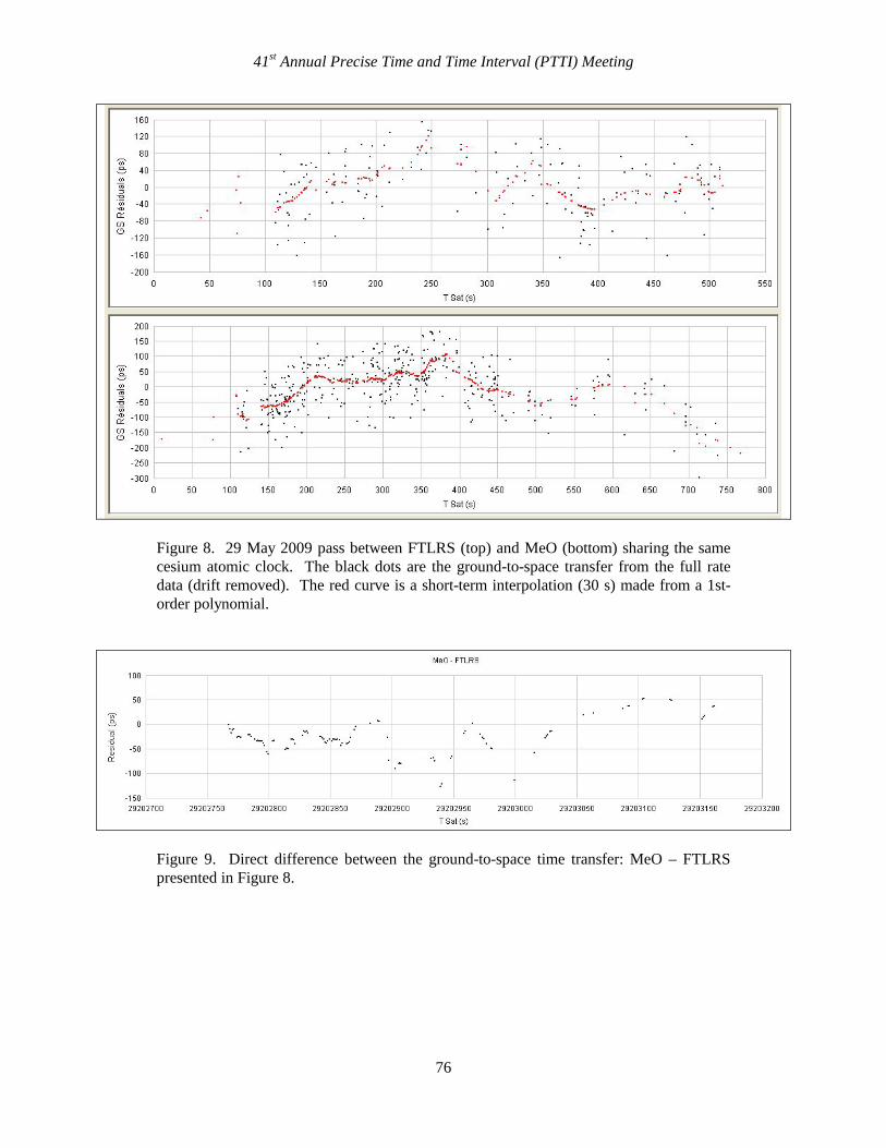
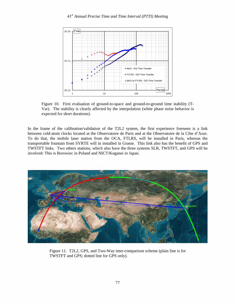
A first computation of ground-to-space and ground-to-ground time transfer is presented in Figures 8 and 9. As explained before, it is necessary to interpolate data in order to have a ground-to-space time transfer at the same moment for the two ground stations and to be able to compute ground-to-ground time transfer by a simple difference of the two ground-to-space time transfers. This is done by fitting a sliding polynomial. The degree and the time length of the polynomial will obviously affect the stability of the time transfer for time integrations smaller than the time length of the polynomial used. For this preliminary analysis, we use a degree 1 polynomial fitted over 30 s. The rms values are of 68 ps for FTLRS ground-to-space transfer, 65 ps for MeO and 42 ps for the ground-to-ground time transfer. It is possible to compute from these data a time stability (Figure 10). Results give a stability of a few tens of picoseconds for integration durations of 1 to 100 seconds. But those results are clearly affected by the polynomial feet. Particularly, one would expect a white phase noise behavior for short durations. Nevertheless, the value of about 20 ps at 100 s is close to the expected stability of T2L2. A FIRST REMOTE GROUND-TO-GROUND TIME TRANSFER EXPERIMENTAL SETUP T2L2 shall allow the calibration of various existing radiofrequency time and frequency transfer systems like GPS or TWSTFT, and comparisons of cold-atom clocks at a level never reached before. Continuous comparison of T2L2 and Two-way shall be possible by using a network of ground stations equipped with both SLR and Two-Way spread out all around the world. Moreover, the availability of both transportable SLR stations (FTLRS – France, TROS – China) and Two-Way stations (TUG – Austria, TimeTech – Germany) shall allow the extension of the network with the possibility of performing some specific experimentations one some major TAI links.
41st Annual Precise Time and Time Interval (PTTI) Meeting
76
Figure 8. 29 May 2009 pass between FTLRS (top) and MeO (bottom) sharing the same cesium atomic clock. The black dots are the ground-to-space transfer from the full rate data (drift removed). The red curve is a short-term interpolation (30 s) made from a 1st- order polynomial.
Figure 9. Direct difference between the ground-to-space time transfer: MeO – FTLRS presented in Figure 8.
41st Annual Precise Time and Time Interval (PTTI) Meeting
77
1E-12
1E-11
1E-10
1 10 100 1000Tau [s]
T-Var
MeO - G/S Time Transfer
FTLRS - G/S Time Transfer
MeO vs FTLRS - G/G Time Transfer
Figure 10. First evaluation of ground-to-space and ground-to-ground time stability (T-Var). The stability is clearly affected by the interpolation (white phase noise behavior is expected for short durations).
In the frame of the calibration/validation of the T2L2 system, the first experience foreseen is a link between cold-atom clocks located at the Observatoire de Paris and at the Observatoire de la Côte d’Azur. To do that, the mobile laser station from the OCA, FTLRS, will be installed in Paris, whereas the transportable fountain from SYRTE will in installed in Grasse. This link also has the benefit of GPS and TWSTFT links. Two others stations, which also have the three systems SLR, TWSTFT, and GPS will be involved: This is Borowiec in Poland and NICT/Koganei in Japan.
Figure 11. T2L2, GPS, and Two-Way inter-comparison scheme (plain line is for TWSTFT and GPS; dotted line for GPS only).
41st Annual Precise Time and Time Interval (PTTI) Meeting
78
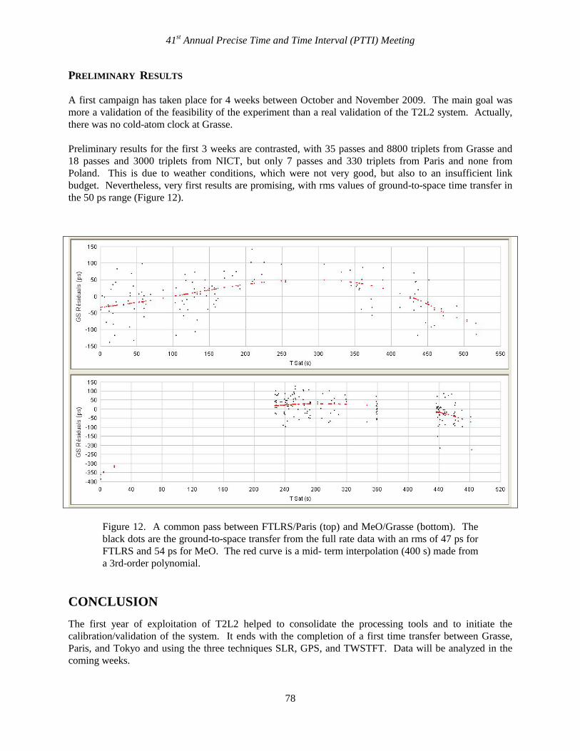
PRELIMINARY RESULTS A first campaign has taken place for 4 weeks between October and November 2009. The main goal was more a validation of the feasibility of the experiment than a real validation of the T2L2 system. Actually, there was no cold-atom clock at Grasse. Preliminary results for the first 3 weeks are contrasted, with 35 passes and 8800 triplets from Grasse and 18 passes and 3000 triplets from NICT, but only 7 passes and 330 triplets from Paris and none from Poland. This is due to weather conditions, which were not very good, but also to an insufficient link budget. Nevertheless, very first results are promising, with rms values of ground-to-space time transfer in the 50 ps range (Figure 12).
Figure 12. A common pass between FTLRS/Paris (top) and MeO/Grasse (bottom). The black dots are the ground-to-space transfer from the full rate data with an rms of 47 ps for FTLRS and 54 ps for MeO. The red curve is a mid- term interpolation (400 s) made from a 3rd-order polynomial.
CONCLUSION The first year of exploitation of T2L2 helped to consolidate the processing tools and to initiate the calibration/validation of the system. It ends with the completion of a first time transfer between Grasse, Paris, and Tokyo and using the three techniques SLR, GPS, and TWSTFT. Data will be analyzed in the coming weeks.
41st Annual Precise Time and Time Interval (PTTI) Meeting
79
Even if models for corrections and interpolation of data need to be improved, rms values of a few tens of picoseconds are observed for both ground-to-space and ground-to-ground time transfer. Clearly, these results should be strengthened in coming months, thanks to the continuous operation of T2L2, but also through a new campaign involving the FTLRS in Paris and cold-atom clocks, scheduled from May 2010. ACKNOWLEDGMENTS The authors wish to thank the FTLRS and MeO teams from the Observatoire de la Côte d’Azur for operating the SLR stations, SYRTE staff for its welcome and support at the Observatoire de Paris, ILRS and the stations of Borowiec and Koganei for their contribution to the T2L2 project through the availability of SLR data, the Time & Frequency Team from CNES, and the French Civil Aviation for its help in making the installation and operation of FTLRS in Paris possible.
REFERENCES [1] P. Fridelance and C. Veillet, 1995, “Operation and Data Analysis in the LASSO Experiment,”
Metrologia, 32, 27-33. [2] P. Fridelance, E. Samain, and C. Veillet, 1997, “T2L2 – Time Transfer by Laser Link: A New Optical
Time Transfer Generation,” Experimental Astronomy, 7, No. 3. [3] P. Guillemot, E. Samain, P. Vrancken, P. Exertier, and S. Leon, 2009, “Time transfer by laser link -
T2L2: An Opportunity to Calibrate RF Links,” in Proceedings of the 40th Annual Precise Time and Time Interval (PTTI) Systems and Applications Meeting, 1-4 December 2008, Reston, Virginia, USA (U.S. Naval Observatory, Washington, D.C.), pp. 95-106.
[4] E. Samain, 1998, “Timing of optical pulses by photodiode in Geiger mode,” Applied Optics, 37, 502-
506. [5] I. Procazka and K. Hamal, 1994, “Recent Achievements in Solid State Detector Technology for Laser
Ranging,” in Proceedings of the 9th International Workshop on Laser Ranging Instrumentation, 7-11 November, Canberra, Australia, Vol. 2, p. 469.
[6] R. H. Kingston, 1978, Detection of Optical and Infrared Radiation (Springer Verlag, Berlin), p. 52. [7] E. Samain, 2002, “An Ultra Stable Event Timer,” in Proceedings of the 13th International Workshop
on Laser Ranging Instrumentation, 7-11 October 2002, Washington, D.C., USA. [8] P. Vrancken, 2008, “Characterization of T2L2 (Time Transfer by Laser Link) on the Jason 2 Ocean
Altimetry Satellite and Micrometric Laser Ranging,” thesis, University of Nice (Sophia Antipolis). [9] P. L. Bender, 1992, “Atmospheric Refraction and Satellite Laser Ranging,” in Refraction of
Transatmospheric Signals in Geodesy: Proceedings of the Symposium (edited by J. C. de Munck and T. A. T. Spoelstra), 19-22 May 1992, The Hague, The Netherlands, pp. 117-125.
[20] P. Exertier, P. Bonnefond, F. Deleflie, F. Barlier, M. Kasser, R. Biancale, and Y. Menardet, 2006,
“Contribution of laser ranging to Earth’s sciences,” Comptes Rendus Géoscience, 338, 958-967.
41st Annual Precise Time and Time Interval (PTTI) Meeting