▪ How can we make sure the circuit works correctly
▪ Designing Testbenches
Carnegie Mellon
3
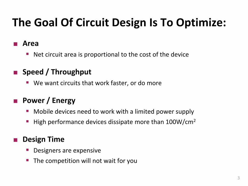
The Goal Of Circuit Design Is To Optimize:
Area
▪ Net circuit area is proportional to the cost of the device
Speed / Throughput
▪ We want circuits that work faster, or do more
Power / Energy
▪ Mobile devices need to work with a limited power supply
▪ High performance devices dissipate more than 100W/cm2
Design Time
▪ Designers are expensive
▪ The competition will not wait for you
Carnegie Mellon
4
Requirements Depend On Application
Carnegie Mellon
5
Timing
Until now, we investigated mainly functionality
What determines how fast a circuit is andhow can we make faster circuits?
A
Y
Time
delay
A Y
Carnegie Mellon
6
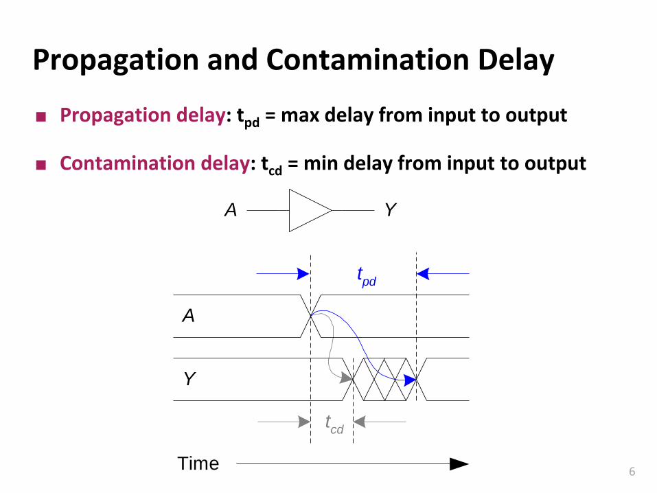
Propagation and Contamination Delay
Propagation delay: tpd = max delay from input to output
Contamination delay: tcd = min delay from input to output
A
Y
Time
A Y
tpd
tcd
Carnegie Mellon
7
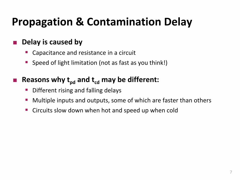
Propagation & Contamination Delay
Delay is caused by
▪ Capacitance and resistance in a circuit
▪ Speed of light limitation (not as fast as you think!)
Reasons why tpd and tcd may be different:
▪ Different rising and falling delays
▪ Multiple inputs and outputs, some of which are faster than others
▪ Circuits slow down when hot and speed up when cold
Carnegie Mellon
8
Critical (Long) and Short Paths
Critical (Long) Path: tpd = 2 tpd_AND + tpd_OR
Short Path: tcd = tcd_AND
AB
C
D Y
Critical Path
Short Path
n1
n2
Carnegie Mellon
9
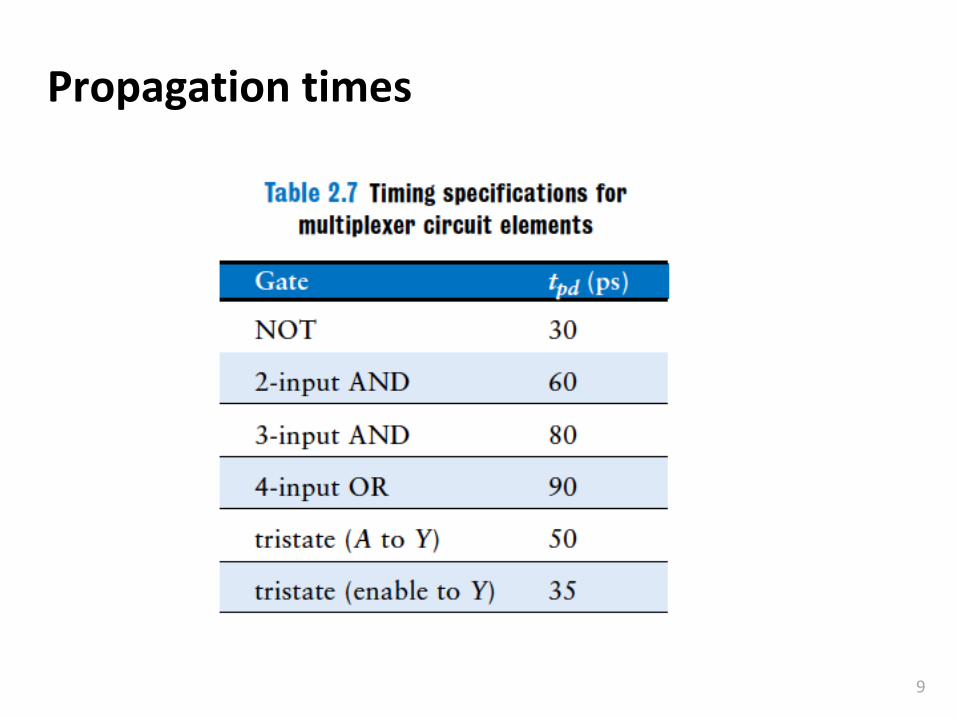
Propagation times
Carnegie Mellon
10
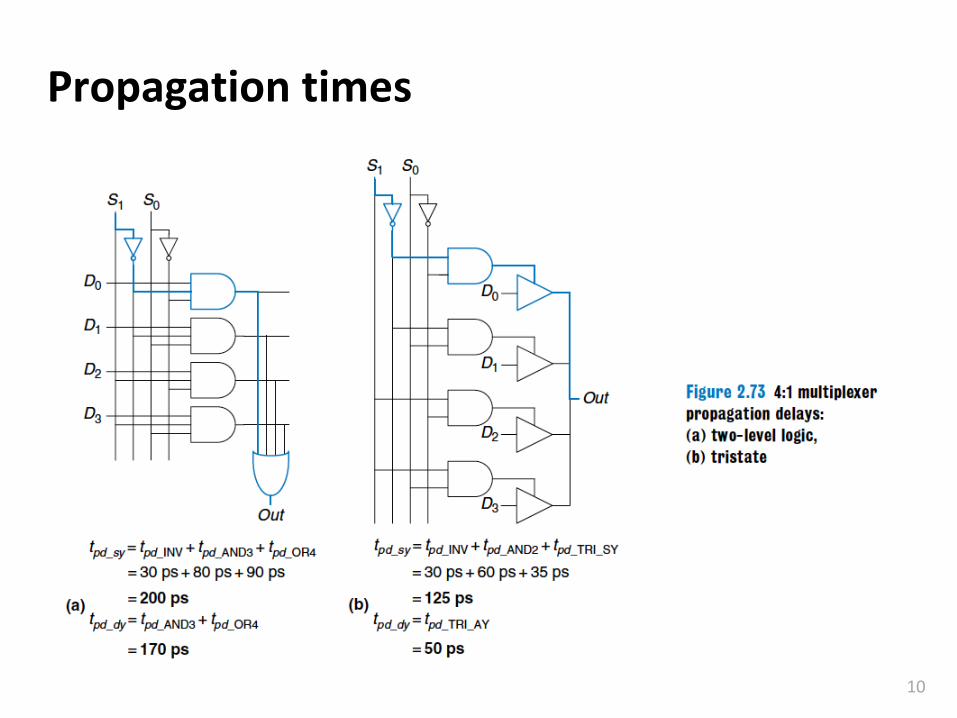
Propagation times
Carnegie Mellon
11
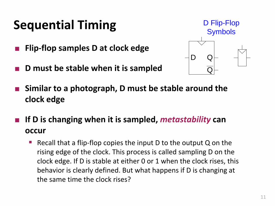
Sequential Timing
Flip-flop samples D at clock edge
D must be stable when it is sampled
Similar to a photograph, D must be stable around the clock edge
If D is changing when it is sampled, metastability can occur
▪ Recall that a flip-flop copies the input D to the output Q on the rising edge of the clock. This process is called sampling D on the clock edge. If D is stable at either 0 or 1 when the clock rises, this behavior is clearly defined. But what happens if D is changing at the same time the clock rises?
D Flip-Flop
Symbols
D Q
Q
Carnegie Mellon
12
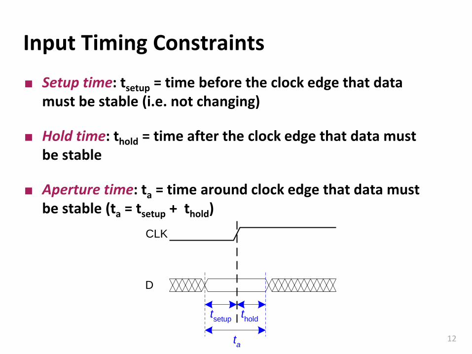
Input Timing Constraints
Setup time: tsetup = time before the clock edge that data must be stable (i.e. not changing)
Hold time: thold = time after the clock edge that data must be stable
Aperture time: ta = time around clock edge that data must be stable (ta = tsetup + thold)
CLK
tsetup
D
thold
ta
Carnegie Mellon
13
Output Timing Constraints
Propagation delay: tpcq = time after clock edge that the output Q is guaranteed to be stable (i.e., to stop changing)
Contamination delay: tccq = time after clock edge that Q might be unstable (i.e., start changing)
CLK
tccq
tpcq
Q
Carnegie Mellon
14
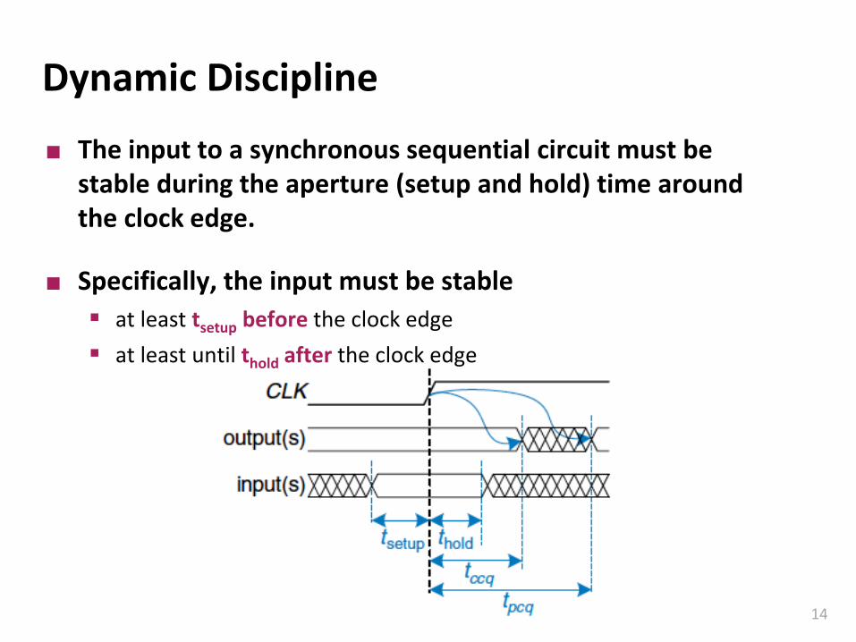
Dynamic Discipline
The input to a synchronous sequential circuit must be stable during the aperture (setup and hold) time around the clock edge.
Specifically, the input must be stable
▪ at least tsetup before the clock edge
▪ at least until thold after the clock edge
Carnegie Mellon
15
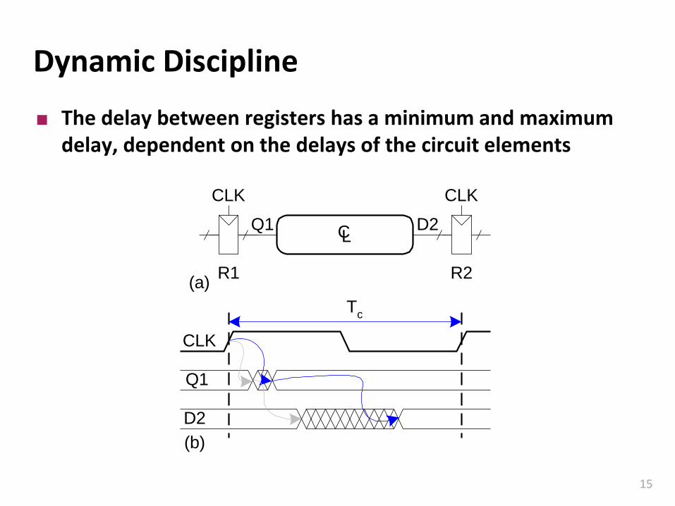
Dynamic Discipline
The delay between registers has a minimum and maximum delay, dependent on the delays of the circuit elements
CL
CLKCLK
R1 R2
Q1 D2
(a)
CLK
Q1
D2
(b)
Tc
Carnegie Mellon
16
Setup Time Constraint
The clock period or cycle time, Tc, is the time between rising edges of a repetitive clock signal. Its reciprocal, fc=1/Tc, is the clock frequency.
All else being the same, increasing the clock frequency increases the work that a digital system can accomplish per unit time.
Frequency is measured in units of Hertz (Hz), or cycles per second:
▪ 1 megahertz (MHz) 106 Hz
▪ 1 gigahertz (GHz) 109 Hz.
Carnegie Mellon
17
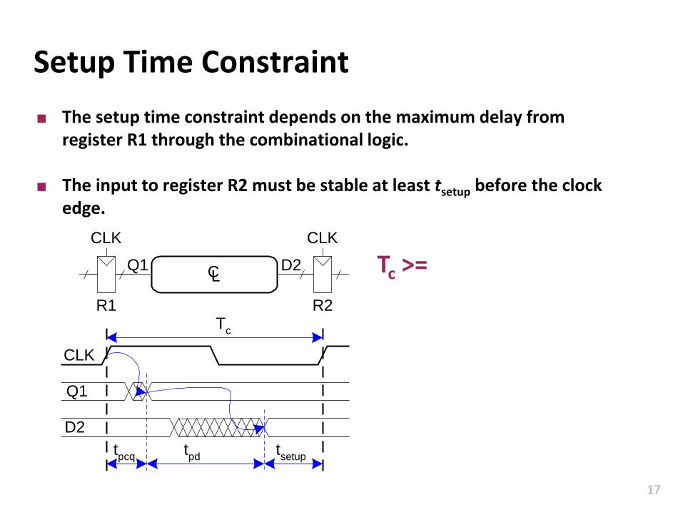
Setup Time Constraint
The setup time constraint depends on the maximum delay from register R1 through the combinational logic.
The input to register R2 must be stable at least tsetup before the clock edge.
CLK
Q1
D2
Tc
tpcq
tpd
tsetup
CL
CLKCLK
Q1 D2
R1 R2
Tc >=
Carnegie Mellon
18
Setup Time Constraint
The setup time constraint depends on the maximum delay from register R1 through the combinational logic.
The input to register R2 must be stable at least tsetup before the clock edge.
CLK
Q1
D2
Tc
tpcq
tpd
tsetup
CL
CLKCLK
Q1 D2
R1 R2
Tc >= tpcq + tpd + tsetup
tpd <=
Carnegie Mellon
19
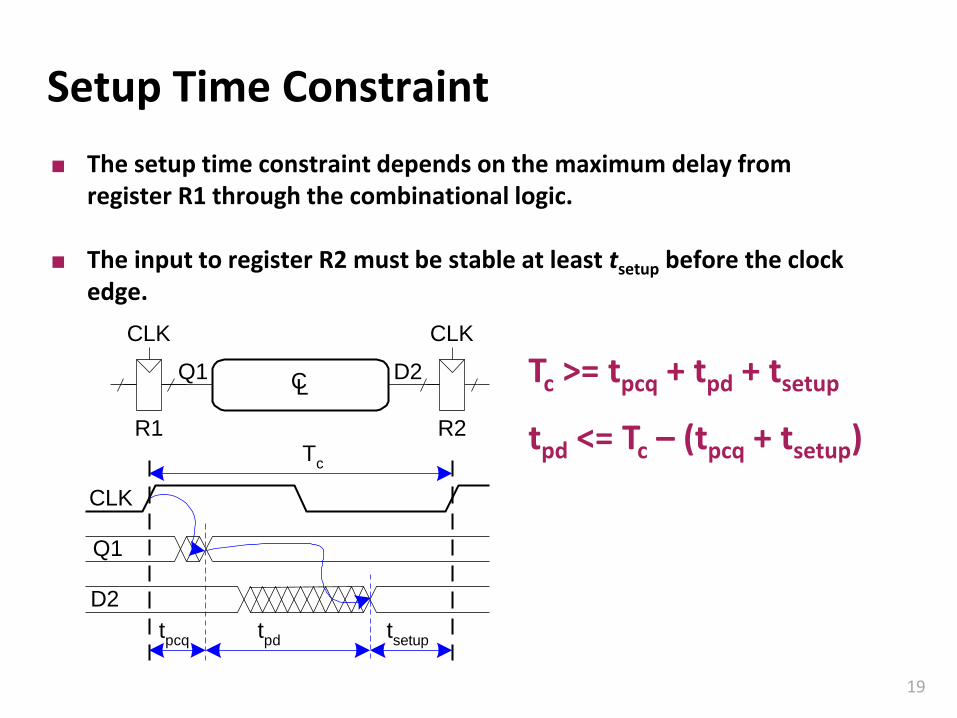
Setup Time Constraint
The setup time constraint depends on the maximum delay from register R1 through the combinational logic.
The input to register R2 must be stable at least tsetup before the clock edge.
CLK
Q1
D2
Tc
tpcq
tpd
tsetup
CL
CLKCLK
Q1 D2
R1 R2
Tc >= tpcq + tpd + tsetup
tpd <= Tc – (tpcq + tsetup)
Carnegie Mellon
20
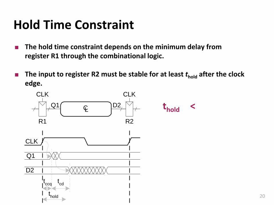
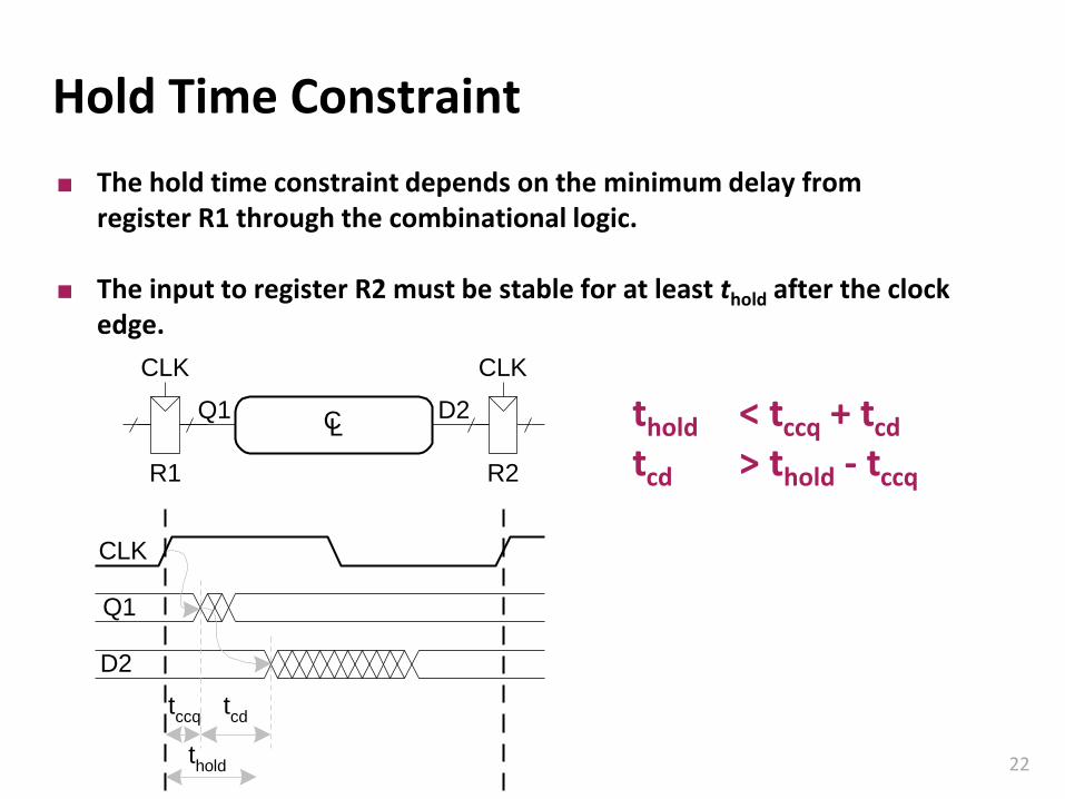
Hold Time Constraint
The hold time constraint depends on the minimum delay from register R1 through the combinational logic.
The input to register R2 must be stable for at least thold after the clock edge.
CLK
Q1
D2
tccq
tcd
thold
CL
CLKCLK
Q1 D2
R1 R2
thold <
Carnegie Mellon
21
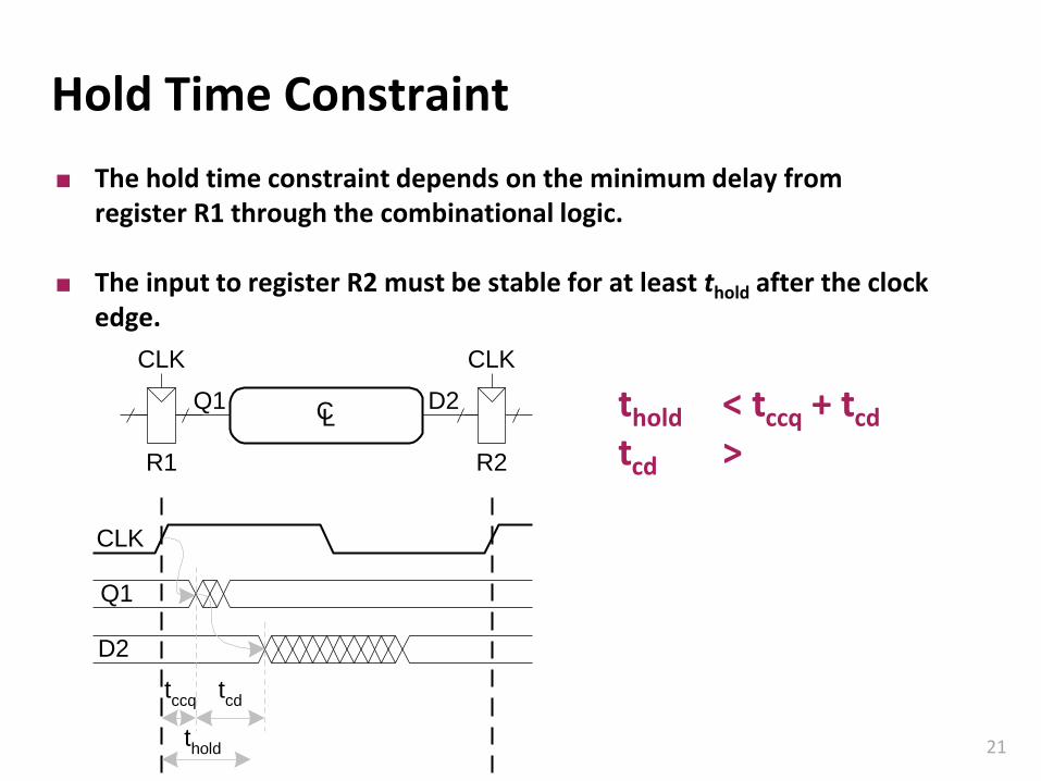
Hold Time Constraint
The hold time constraint depends on the minimum delay from register R1 through the combinational logic.
The input to register R2 must be stable for at least thold after the clock edge.
CLK
Q1
D2
tccq
tcd
thold
CL
CLKCLK
Q1 D2
R1 R2
thold < tccq + tcd
tcd >
Carnegie Mellon
22
Hold Time Constraint
The hold time constraint depends on the minimum delay from register R1 through the combinational logic.
The input to register R2 must be stable for at least thold after the clock edge.
CLK
Q1
D2
tccq
tcd
thold
CL
CLKCLK
Q1 D2
R1 R2
thold < tccq + tcd
tcd > thold - tccq
Carnegie Mellon
23
Timing AnalysisCLK CLK
A
B
C
D
X'
Y'
X
Y
per
gate
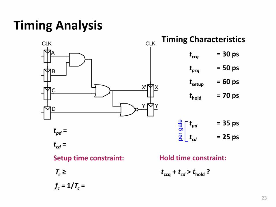
Timing Characteristics
tccq = 30 ps
tpcq = 50 ps
tsetup = 60 ps
thold = 70 ps
tpd = 35 ps
tcd = 25 pstpd =
tcd =
Setup time constraint:
Tc ≥
fc = 1/Tc =
Hold time constraint:
tccq + tcd > thold ?
Carnegie Mellon
24
Timing AnalysisCLK CLK
A
B
C
D
X'
Y'
X
Y
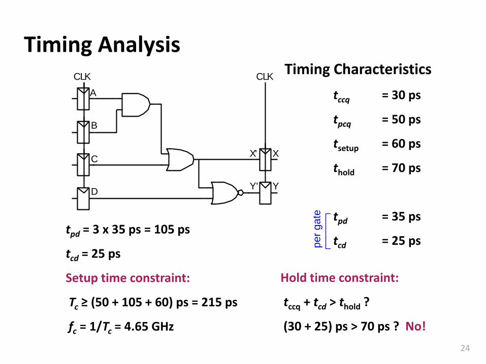
tpd = 3 x 35 ps = 105 ps
tcd = 25 ps
Setup time constraint:
Tc ≥ (50 + 105 + 60) ps = 215 ps
fc = 1/Tc = 4.65 GHz
Hold time constraint:
tccq + tcd > thold ?
(30 + 25) ps > 70 ps ? No!p
er
gate
Timing Characteristics
tccq = 30 ps
tpcq = 50 ps
tsetup = 60 ps
thold = 70 ps
tpd = 35 ps
tcd = 25 ps
Carnegie Mellon
25
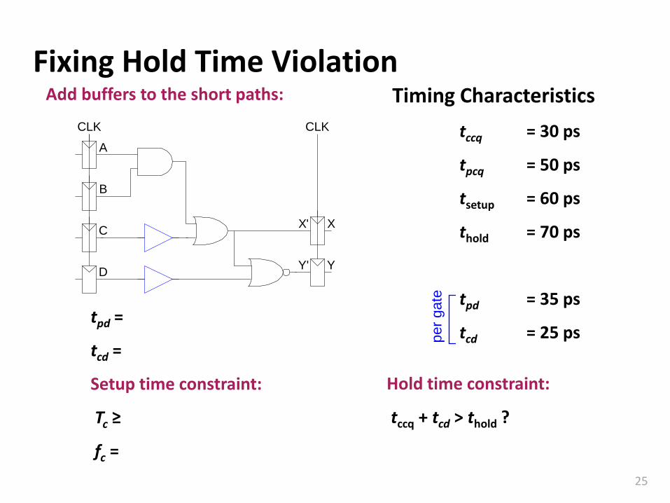
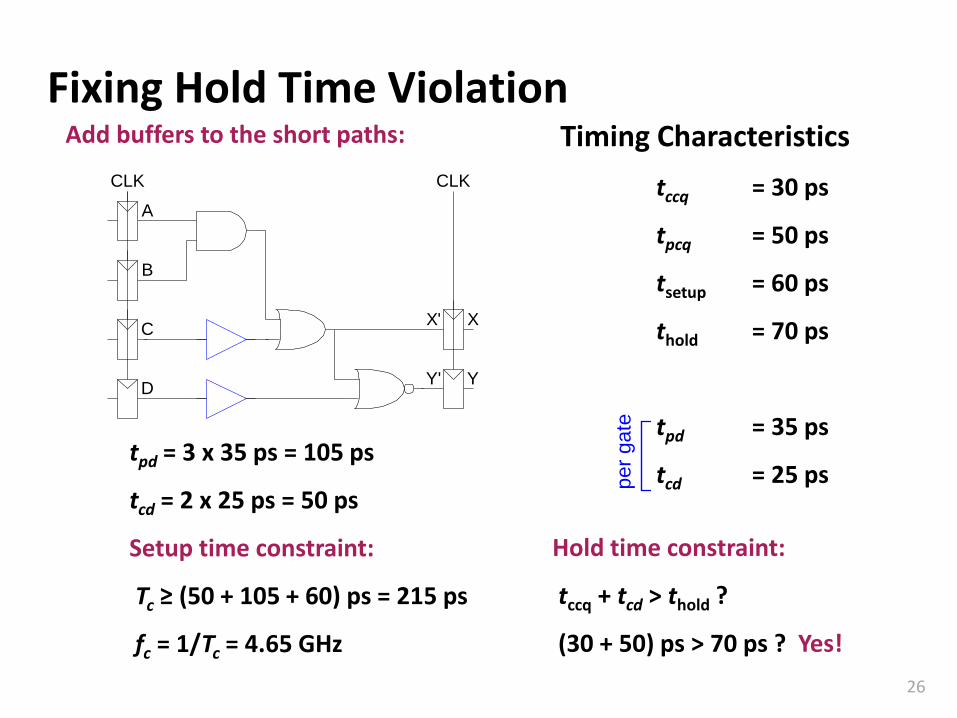
Fixing Hold Time Violation
CLK CLK
A
B
C
D
X'
Y'
X
Y
tpd =
tcd =
Setup time constraint:
Tc ≥
fc =
Hold time constraint:
tccq + tcd > thold ?
Add buffers to the short paths:
per
gate
Timing Characteristics
tccq = 30 ps
tpcq = 50 ps
tsetup = 60 ps
thold = 70 ps
tpd = 35 ps
tcd = 25 ps
Carnegie Mellon
26
Fixing Hold Time Violation
CLK CLK
A
B
C
D
X'
Y'
X
Y
tpd = 3 x 35 ps = 105 ps
tcd = 2 x 25 ps = 50 ps
Setup time constraint:
Tc ≥ (50 + 105 + 60) ps = 215 ps
fc = 1/Tc = 4.65 GHz
Hold time constraint:
tccq + tcd > thold ?
(30 + 50) ps > 70 ps ? Yes!
Add buffers to the short paths:
per
gate
Timing Characteristics
tccq = 30 ps
tpcq = 50 ps
tsetup = 60 ps
thold = 70 ps
tpd = 35 ps
tcd = 25 ps
Carnegie Mellon
27
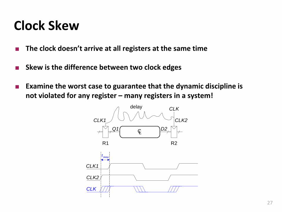
Clock Skew
The clock doesn’t arrive at all registers at the same time
Skew is the difference between two clock edges
Examine the worst case to guarantee that the dynamic discipline is not violated for any register – many registers in a system!
tskew
CLK1
CLK2
CL
CLK2CLK1
R1 R2
Q1 D2
CLKdelay
CLK
Carnegie Mellon
28
Preikestolen - Norway6
00
m
Carnegie Mellon
29
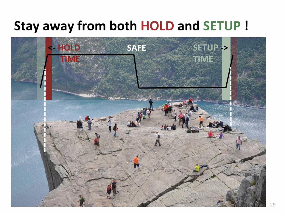
Stay away from both HOLD and SETUP !
<- HOLDTIME
SETUP ->TIME
SAFE
Carnegie Mellon
30
How Do You Know That A Circuit Works?
You have written the Verilog code of a circuit
▪ Does it work correctly?
▪ Even if the syntax is correct, it might do what you want?
▪ What exactly it is that you want anyway?
Trial and error can be costly
▪ You need to ‘test’ your circuit in advance
In modern digital designs, functional verification is the most time consuming design stage.
Carnegie Mellon
31
The Idea Behind A Testbench
Using a computer simulator to test your circuit
▪ You instantiate your design
▪ Supply the circuit with some inputs
▪ See what it does
▪ Does it return the “correct” outputs?
Carnegie Mellon
32
Testbenches
HDL code written to test another HDL module, the device under test (dut), also called the unit under test (uut)
Not synthesizeable
Types of testbenches:
▪ Simple testbench
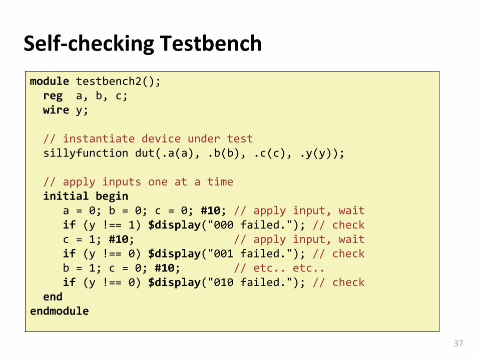
▪ Self-checking testbench
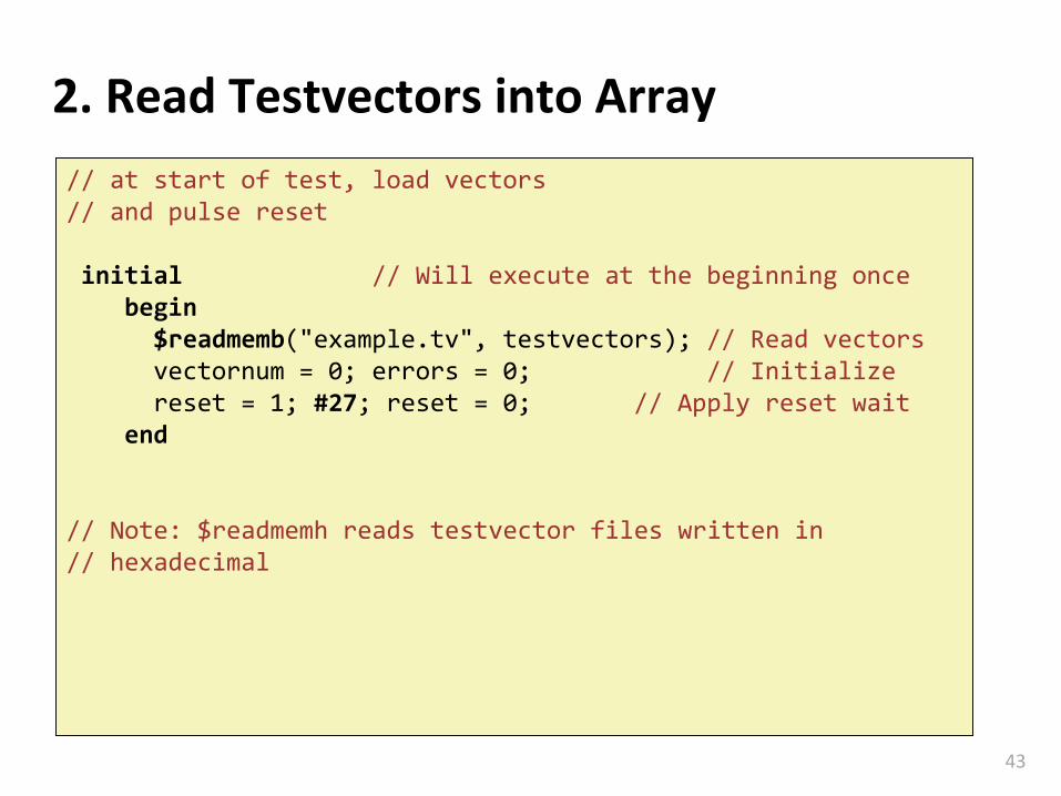
▪ Self-checking testbench with testvectors
Carnegie Mellon
33
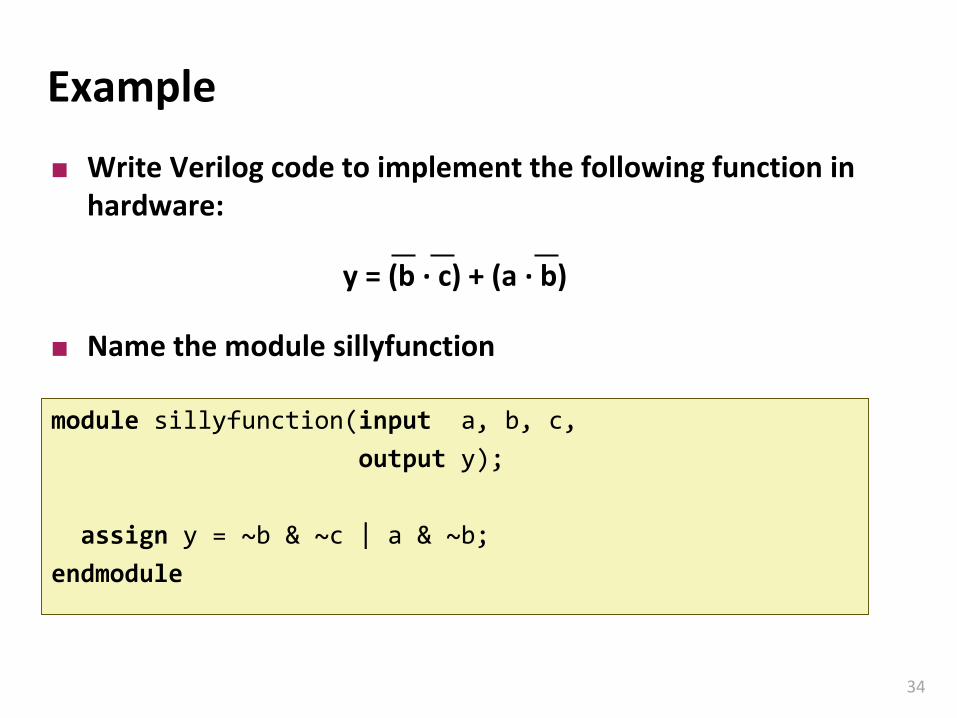
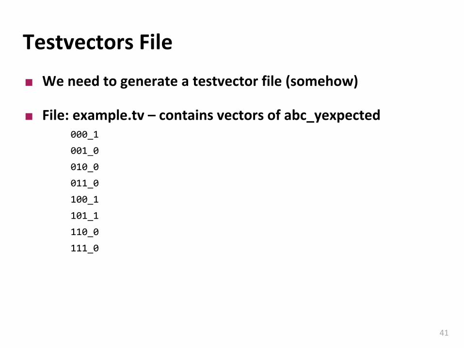
Example
Write Verilog code to implement the following function in hardware:
y = (b ∙ c) + (a ∙ b)
Name the module sillyfunction
Carnegie Mellon
34
Example
module sillyfunction(input a, b, c,
output y);
assign y = ~b & ~c | a & ~b;
endmodule
Write Verilog code to implement the following function in hardware:
y = (b ∙ c) + (a ∙ b)
Name the module sillyfunction
Carnegie Mellon
35
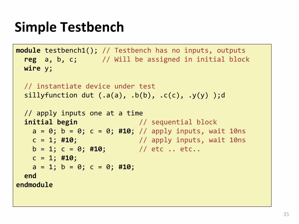
Simple Testbench
module testbench1(); // Testbench has no inputs, outputsreg a, b, c; // Will be assigned in initial blockwire y;