29
1 Timing Counter analysis C.Voena - INFN Roma for the TC group MEG Review Meeting Feb 17 th 2010
| Date post: | 31-Dec-2015 |
| Category: |
Documents |
| Upload: | price-noble |
| View: | 12 times |
| Download: | 1 times |

1
Timing Counter analysis
C.Voena - INFN Romafor the TC group
MEG Review MeetingFeb 17th 2010
2
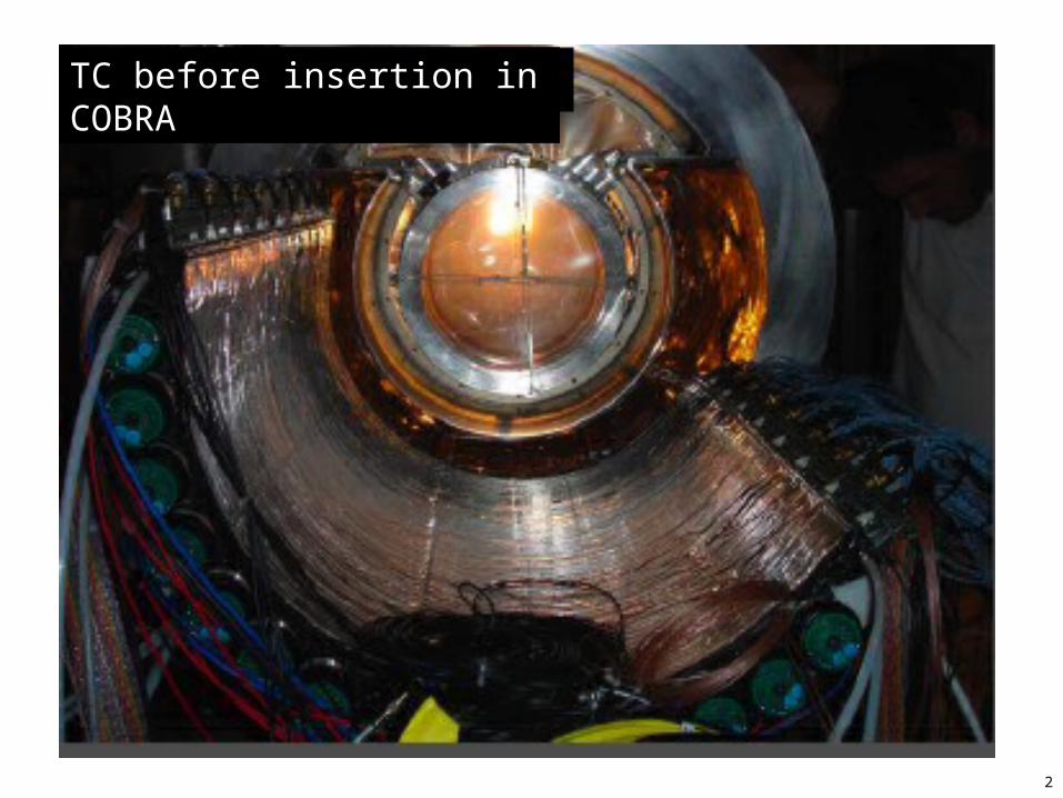
TC before insertion in COBRA
3
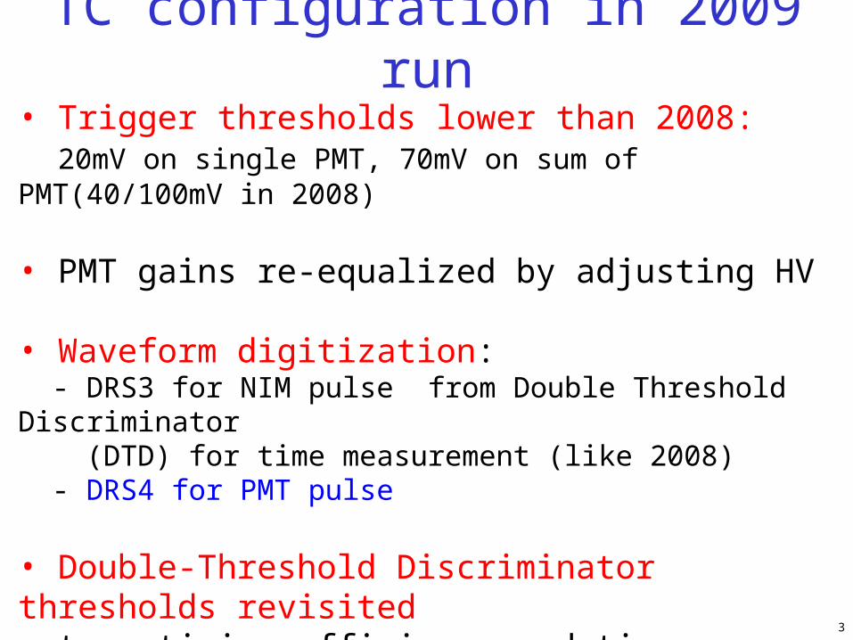
TC configuration in 2009 run• Trigger thresholds lower than 2008: 20mV on single PMT, 70mV on sum of PMT(40/100mV in 2008)
• PMT gains re-equalized by adjusting HV
• Waveform digitization: - DRS3 for NIM pulse from Double Threshold Discriminator (DTD) for time measurement (like 2008) - DRS4 for PMT pulse
• Double-Threshold Discriminator thresholds revisited to optimize efficiency and time resolution 2009: 25/600 mV 2008:25/800mV
4
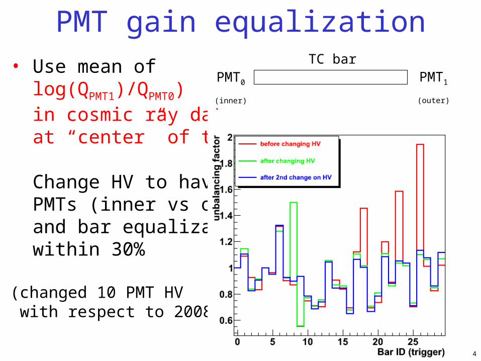
PMT gain equalization• Use mean of log(QPMT1)/QPMT0) in cosmic ray data at “center” of the bar
Change HV to have PMTs (inner vs outer) and bar equalization within 30%
(changed 10 PMT HV with respect to 2008)
PMT0
(inner)
PMT1
(outer)
TC bar

5
DTD thresholds scanLow threshold: as low as possible (first photoelectron) => Can improve time resolution
- Limited by noise- No improvement seen lowering this threshold (tried 10-17 mV) => left at 25mV which was already optimal value!
High threshold: select good pulses (tracks producing enough p.e., Landau peak)
- Lowered to 600mV (was 800mV) to have more acceptance on positron with lower pulses
800-25400-25250-25
Eloss (a.u.)

6
TC time measurement
€
t0 = T +z
veff+ b0 +
c0
A0
e+
L
zPMT0
€
t1 = T +L − z
veff+ b1 +
c1
A1
.
t0,1= extracted with waveform template fits to NIM pulsesfrom Double Threshold Discriminator for PMT0,1
T : time of positron at the impact point on first hit bar (connected to the positron track from DCH)
z : impact point along bar length
effective velocity
PMT1
amplitude of PMT signal
7
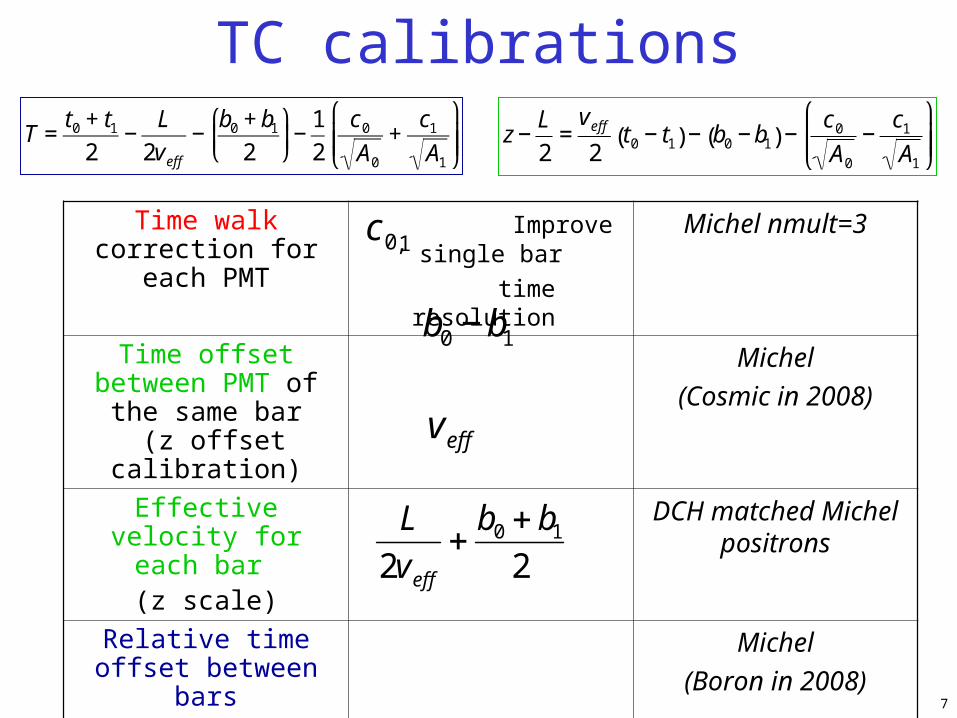
TC calibrations
Time walk correction for each PMT
Improve single bar
time resolution
Michel nmult=3
Time offset between PMT of the same bar (z offset calibration)
Michel
(Cosmic in 2008)
Effective velocity for each bar (z scale)
DCH matched Michel positrons
Relative time offset between bars
Michel
(Boron in 2008)
Absolute time offset between positron and
photon
_ Dalitz 0
€
b0 −b1
L
2veffb0 b1
2
veff€
c0,1€
T =t0 + t1
2−L
2veff−b0 + b1
2
⎛
⎝ ⎜
⎞
⎠ ⎟−
1
2
c0
A0
+c1
A1
⎛
⎝ ⎜ ⎜
⎞
⎠ ⎟ ⎟
€
z −L
2=veff2t0 − t1( ) − b0 −b1( ) −
c0
A0
−c1
A1
⎛
⎝ ⎜ ⎜
⎞
⎠ ⎟ ⎟
8
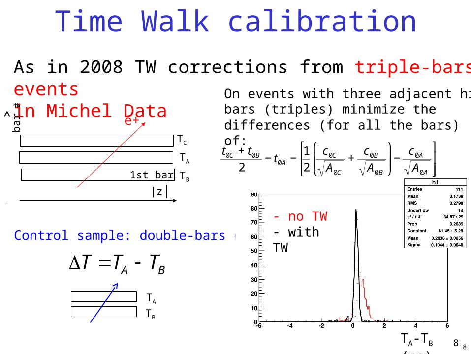
As in 2008 TW corrections from triple-bars events in Michel Data
8
On events with three adjacent hit bars (triples) minimize the differences (for all the bars) of:
T TA TB
Time Walk calibration
|z|
bar
#
e+
1st bar
€
t0C + t0B2
− t0A −1
2
c0C
A0C
+c0B
A0B
⎛
⎝ ⎜ ⎜
⎞
⎠ ⎟ ⎟−c0A
A0A
⎡
⎣ ⎢ ⎢
⎤
⎦ ⎥ ⎥.
TB
TA
TC
Control sample: double-bars events
TA
TB
TA-TB (ns)
- no TW- with TW

9
2009 resolution2008 resolution
from double-bars events: upper limit on: TC intrinsic resolution + DRS resolution (~10ps)
TC Time Resolution
€
σΔT
2
Upper limit on timeresolution (σ) in 70-100 ps range in 2009 (exceptbar 21)
Slightly worse than2008: under study.Still adequate for MEG performances

10
Difference of PMTs electronic offsets- Needed for z measurement and to combine time measurement of adjacent hits- Use Michel matched positrons instead of previously used cosmic rays
z-offset calibration
Obtained by aligning mean of ztrack-zTC
ztrack= z predicted extrapolating track at TCzTC = z measured by TC
The procedure assumes φ-symmetry

11
Good alignment of bars as can be seen from hit-map
TC hit-map with z-offset calibration
trigger “MEG” data before calibration
trigger “MEG” data after calibration

12
Temporary calibration - Michel matched positrons
Use ztrack as estimate of z at TC - Eventually use fibers for z mesurement
z-scale:effective velocity
€
z =veff2t0 − t1( )
veff = 14.8 cm/ns
t0-t1(ns)
z tra
ck –
z ce
nte
r (c
m)

13
LIB
Double-bar events in Michel data
€
toff , j − toff ,0 = Tk −Tk−1( )mean −LIBc
⎡ ⎣ ⎢
⎤ ⎦ ⎥
k=1
j
∑
€
toff , j − toff ,15 = Tk −Tk−1( )mean −LIBc
⎡ ⎣ ⎢
⎤ ⎦ ⎥
k=16
j
∑
After that, Downstream bars are aligned with bar #0 and Upstream bars are aligned with bar#15 (there are not double-bar events which connect US and DS)
LIB = Inter-Bar path, taken from MC LIB/c ~200ps
Inter-bar time offset calibration
€
Tj = Ti +LIBc
Tj
Ti
Offsets for DS bars
Offsets for US bars
€
toff =L
2veff+b0 + b1
2
€
ΔT = Tj −Ti
14
Mea
n of
T
γγ (
ns)
TC bar #
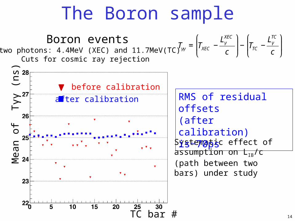
before calibration
after calibration €
Tγγ = TXEC −LγXEC
c
⎛
⎝ ⎜
⎞
⎠ ⎟− TTC −
LγTC
c
⎛
⎝ ⎜
⎞
⎠ ⎟
Boron events two photons: 4.4MeV (XEC) and 11.7MeV(TC)
Cuts for cosmic ray rejection
The Boron sample
Systematic effect of assumption on LIB/c (path between twobars) under study
RMS of residual offsets(after calibration) is~70ps
15
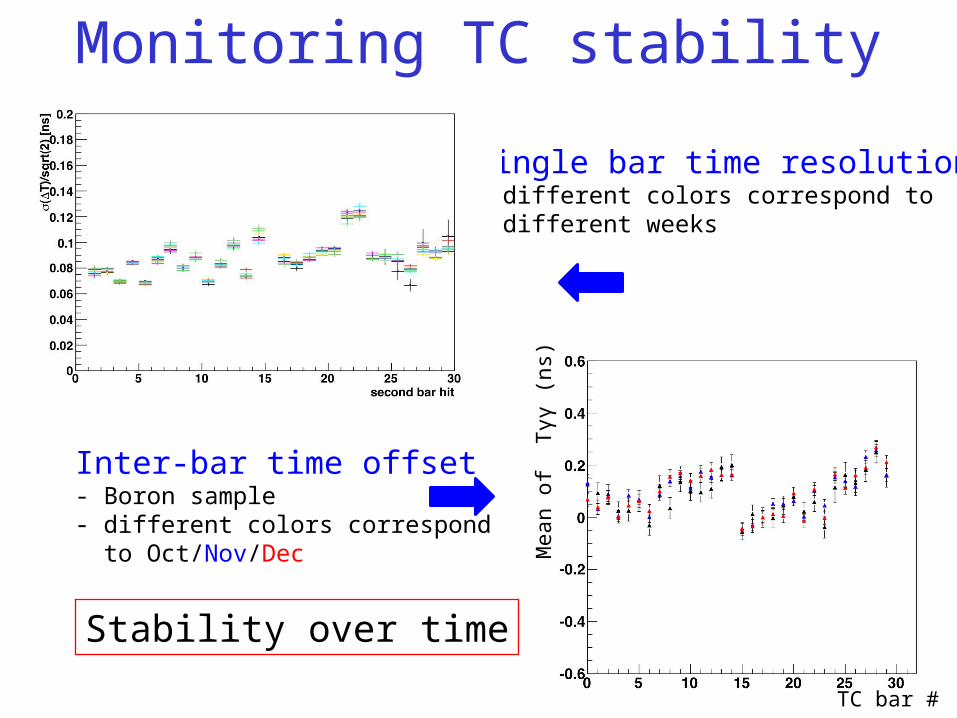
Monitoring TC stability
Single bar time resolution- different colors correspond to different weeks
Inter-bar time offset- Boron sample- different colors correspond to Oct/Nov/Dec
TC bar #
Mea
n of
Tγγ
(ns
)
Stability over time

16
0 e(e ) Dalitz 0 events
– Same topology as signal
– Worse resolution due to LH2 target Do not look at time resolution!
Absolute XEC-TC time offsets
€
Teγ = TXEC −LγXEC
c
⎛
⎝ ⎜
⎞
⎠ ⎟− TTC −
LeTC
c
⎛
⎝ ⎜
⎞
⎠ ⎟
Teγ for reference bar
Center of blinding window
(for pre-selection)μ=24.9ns
- Dalitz data suffer from
hardware problem on
DCH side (DRS) that
may affect resolution
Teγ (ns)

17
DCH-TC match- Extrapolated track at bar surface - Reject bars with multiple hits- Reject pairs TC-DCH with bad ztrack-zTC , rtrack-rTC and bad χ2 of match (multiple turns taken into account)
Positron time :- If more than 1 TC hit in matched cluster: combine time measurement taking into account track length between bars- Correct ad-hoc for Te+ correlation with ztrack-zTC
TC-DCH match and Te+ algorithm
Plans: do systematic studies of the algorithms (Monte Carlo and Dalitz sample)
€
Te+ = TTC −LeTC
c
18
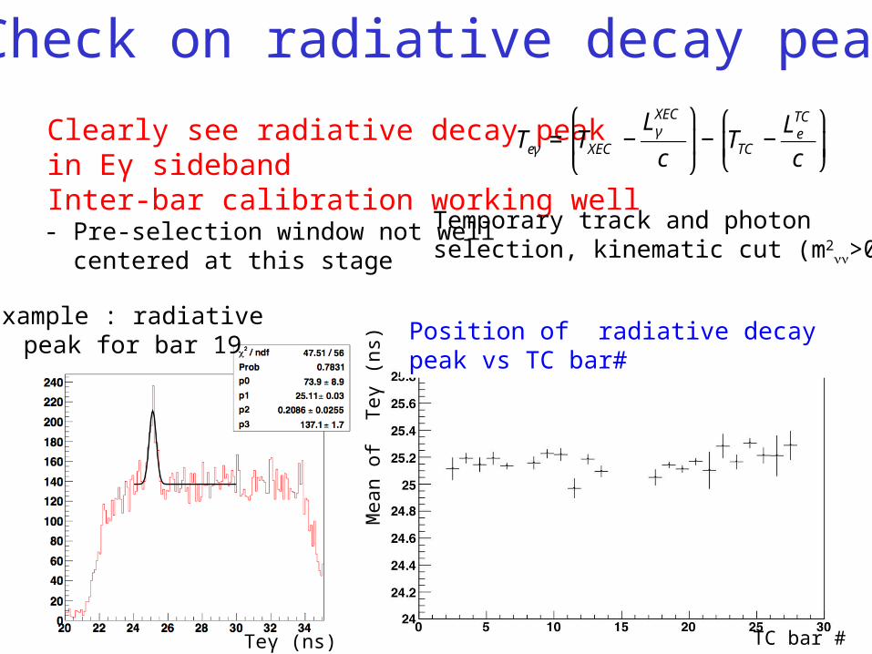
Check on radiative decay peak
Clearly see radiative decay peak in Eγ sideband Inter-bar calibration working well - Pre-selection window not well centered at this stage
€
Teγ = TXEC −LγXEC
c
⎛
⎝ ⎜
⎞
⎠ ⎟− TTC −
LeTC
c
⎛
⎝ ⎜
⎞
⎠ ⎟
Example : radiative peak for bar 19
Teγ (ns) TC bar #
Temporary track and photonselection, kinematic cut (m2
νν>0)
Mea
n of
Teγ
(ns
)
Position of radiative decay peak vs TC bar#
19
Summary
• TC bars very stable during 2009 run - Ready for the incoming long data-taking
• Calibration strategy applied successfully to 2009 data
• TC intrinsic time resolution < 70-100ps (a little worse than 2008, investigating)
- one of the best Timing Counter detector
• Calibration methods and analysis algorithm constantly improving
20
Backup
21
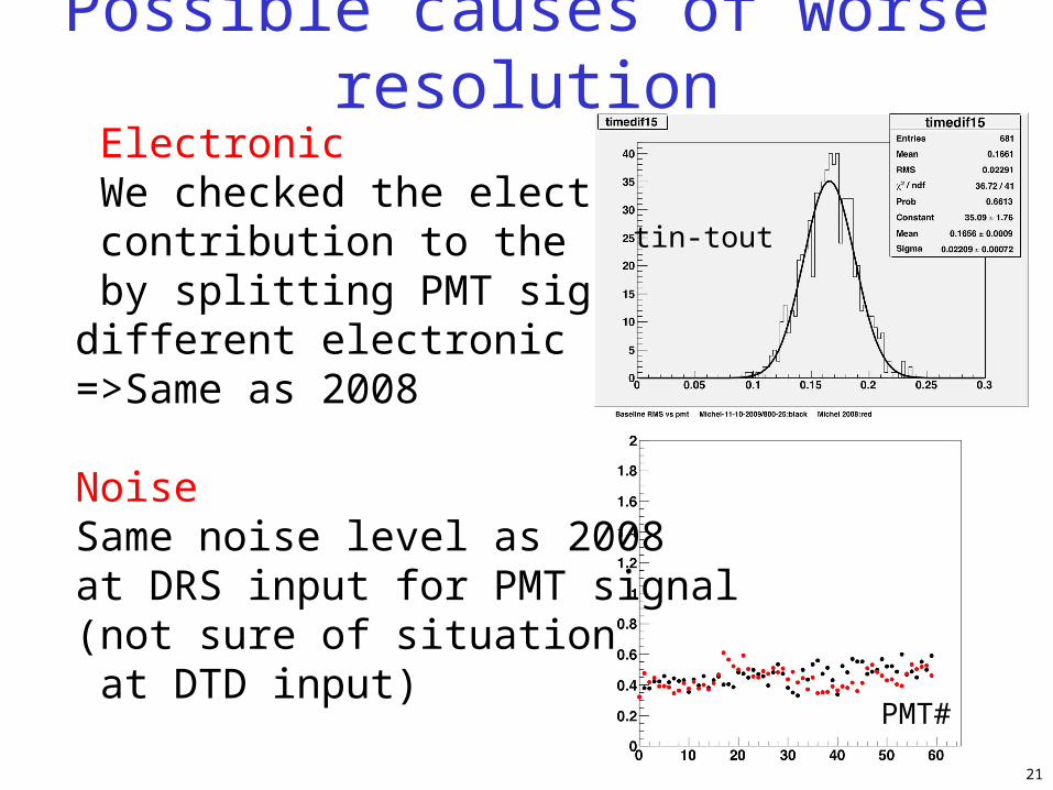
Electronic We checked the electronic contribution to the resolution by splitting PMT signal in two different electronic channels =>Same as 2008
Noise Same noise level as 2008 at DRS input for PMT signal (not sure of situation at DTD input)
tin-tout
PMT#
Possible causes of worse resolution
22
Other possible causes: deterioration of PMT-bar coupling? Less scintillation light?
1) (relative) width of Landau peak: done but not conclusive, dominated by Eloss fluctuation
2) change of Λeff. Underway but may be not conclusive since we do not have precise measurement of veff
3) Tests in labs foreseen
Possible causes of worse resolution

23
2008
2009
Width of CR landau distr.

24
before calibrationz-offset calibration from Michel dataz-offset calibration from CR data
z1
z2
Second hit bar number
Mean of DZ=z2-z1in double bar events (cm)
Applying z-calibration to doubles

25
Boron: High energy photonHigh energy photon in XECLow energy photon in XEC

26
CR backgound in Boron Sample
Tγγ (ns)
Black: boron data Red: CR data taken with same Boron trg

27
Resolution in Boron Sample
Tγγ resolution (ns) vs TC bar: 2009, 2008 (July processing)
Tγγ resolution vs Time

28
Multiple hits of TC bars
|z|
Positron track
**
TC hit position: dz = |z2|-|z1| Bar 1 Bar 2
|z|
*
*
dz>0
dz< 0
1st bar with multiple hit
29
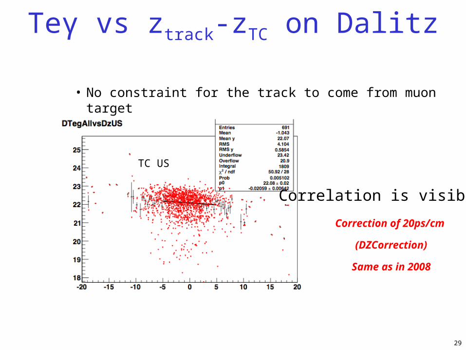
Teγ vs ztrack-zTC on Dalitz
• No constraint for the track to come from muon target
TC US
Correlation is visible
Correction of 20ps/cm
(DZCorrection)
Same as in 2008


