tinyAVR 1-series Training Getting Started with the tinyAVRreg 1-series
Prerequisites
bull Hardware Prerequisitesndash Microchip ATtiny817 Xplained Pro boardndash Micro-USB cable (Type-AMicro-B)ndash One female-to-female wirendash Internet connection
bull Software Prerequisitesndash Atmel Studio 70ndash Atmel Studio ATtiny_DFP version 12112 or abovendash A list of supported browsers can be found here httpstartatmelcomstatichelp rarr
Requirements and Compatibility rarr Supported Web Browsersbull Estimated Completion Time 120 minutes
Introduction
This hands-on training will demonstrate how to develop AVRreg applications in Atmel Studio and AtmelSTART along with the rich user interface and other great development tools that they provide
Atmel START helps to get started with Microchip microcontroller development It allows you to selectMCU configure software components drivers middleware and example projects to the embeddedapplication in a usable and optimized manner Once the configuration is complete the project can begenerated in Atmel Studio or another third-party development tool An IDE is used to develop the coderequired to extend the functionality of the project into the final product as well as compile program anddebug the downloaded code
With Atmel START
bull Get help selecting the MCU based on both software and hardware requirementsbull Find and develop examplesbull Configure drivers middleware and example projectsbull Get help with setting up a valid PINMUX layoutbull Configure system clock settings
The ATtiny817 Xplained Pro evaluation kit is a hardware platform for evaluating the ATtiny817microcontroller A fully integrated embedded debugger is included in the kit which provides seamlessintegration with Atmel Studio Easy access to the features of the ATtiny817 is enabled by the kitfacilitating easy integration of the device in a customer design
This training module demonstrates how to configure the application in Atmel START reconfigure theAtmel START project and continue the implementation in Atmel Studio 7
copy 2018 Microchip Technology Inc Training Manual DS40001949B-page 1
The peripherals used to create applications are GPIO timers TCA and TCB Event System USART CCL(Configurable Custom Logic) and PIT (Periodic Interrupt Interval)
Figure 1 ATtiny817 Xplained Pro
The following topics are covered
bull Driver Configuration in Atmel STARTbull PINMUX driver configuration and check LED toggle on button pressbull Generate a PWM by using timer counter A (TCA) and implement Variable-Pulse-Width by using the
RTC interruptbull Duty cycle and frequency measurement using input capture mode of TCBbull USART configurationbull Use the Data Visualizer tool to send data to the serial terminalbull CCL (Configurable Custom Logic) A programmable logic peripheral which can be connected to the
device pins events or peripherals which allows the user to eliminate external logic gates for simpleglue logic functions Here configure CCL to generate the specific signal using the event from GPIO andtwo PWM signals
Note Solution projects for this training can be found in Atmel START rarr BROWSE EXAMPLES GettingStarted with the tinyAVRreg 1-series
tinyAVR 1-series Training
copy 2018 Microchip Technology Inc Training Manual DS40001949B-page 2
4 Assignment 2 Generate PWM Measure Duty Cycle and Frequency1941 TCA Driver1942 RTC Driver 2543 TCB Driver2744 Event System Driver2945 USART Driver3146 Generate Project Code Development 32
5 Assignment 3 Basis of a Binary Frequency-Shift Keying Scheme 4151 CCL Driver4252 Event System Driver4453 PIT Driver 4654 Generate Project Run Code46
6 Conclusion49
7 Get Source Code from Atmel | START 50
8 Revision History51
The Microchip Web Site 52
Customer Change Notification Service52
Customer Support 52
Microchip Devices Code Protection Feature 52
Legal Notice53
Trademarks 53
copy 2018 Microchip Technology Inc Training Manual DS40001949B-page 3
Quality Management System Certified by DNV54
Worldwide Sales and Service55
tinyAVR 1-series Training
copy 2018 Microchip Technology Inc Training Manual DS40001949B-page 4
1 Relevant DevicesThis chapter lists the relevant devices for this document
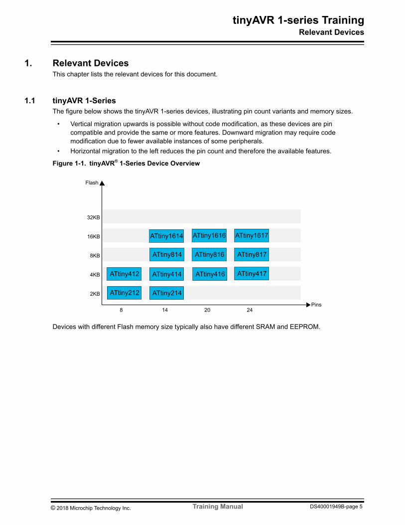
11 tinyAVR 1-SeriesThe figure below shows the tinyAVR 1-series devices illustrating pin count variants and memory sizes
bull Vertical migration upwards is possible without code modification as these devices are pincompatible and provide the same or more features Downward migration may require codemodification due to fewer available instances of some peripherals
bull Horizontal migration to the left reduces the pin count and therefore the available features
Figure 1-1 tinyAVRreg 1-Series Device Overview
32KB
16KB
8KB
4KB
2KB
8 14 20 24Pins
Flash
ATtiny816 ATtiny817ATtiny814
ATtiny417
ATtiny1616 ATtiny1617
ATtiny414 ATtiny416ATtiny412
ATtiny214ATtiny212
ATtiny1614
Devices with different Flash memory size typically also have different SRAM and EEPROM
tinyAVR 1-series TrainingRelevant Devices
copy 2018 Microchip Technology Inc Training Manual DS40001949B-page 5
2 Icon Key IdentifiersThe following icons are used in this document to identify the different assignment sections and to reducethe complexity
Info Delivers contextual information about a specific topic
Tip Highlights useful tips and techniques
To do Highlights objectives to be completed
Result Highlights the expected result of an assignment step
WARNING Indicates important information
Execute Highlights actions to be executed out of the target when necessary
tinyAVR 1-series TrainingIcon Key Identifiers
copy 2018 Microchip Technology Inc Training Manual DS40001949B-page 6
3 Assignment 1 LED TOGGLE ApplicationAn application will be developed that controls the LED using the push-button on the board The LED willbe OFF on pressing the button default state is LED ON
A project will be configured in Atmel START using PINMUX driver configuration and clock configurationfollowed by generation of the corresponding Atmel Studio 7 project
The code will be developed in Atmel Studio 7 using PINMUX driver functions generated by Atmel STARTconfiguration
On the ATtiny817 Xplained Pro board LED0 is connected to pin PB4 and the push-button (SW0) isconnected to pin PB5
For applicationbull Peripherals used GPIO (PB4 PB5)bull Clock 333 MHz
31 Atmel START Project CreationConfigure the PINMUX driver and CLOCK in Atmel START and create the project
To do Create a new Atmel START Project
1 Open Atmel Studio2 Select File rarr New rarr Atmel Start Project3 The CREATE NEW PROJECT window appears within Atmel Studio 7 In the Filter on device
text box enter 817X then select ATtiny817 Xplained Pro from the list and verify that ATtiny817Xplained Pro is highlighted then click on CREATE NEW PROJECT as shown belowFigure 3-1 CREATE NEW PROJECT
Info Now the MY SOFTWARE COMPONENTS window appears
tinyAVR 1-series TrainingAssignment 1 LED TOGGLE Application
copy 2018 Microchip Technology Inc Training Manual DS40001949B-page 7
4 In MY SOFTWARE COMPONENTS windowndash 1 Click on MY PROJECTndash 2 Select Rename Component
Figure 3-2 Rename Component
Info Now the RENAME COMPONENT window will be displayed
5 In the RENAME COMPONENT window specify the new project name as Assignment_ATtiny817and select Rename
6 Now for PINMUX configuration click on the navigation tab on the left side of the window
Info The PINMUX configurator displays an illustration of the device package selected Itshows which pins are currently used by different peripherals The GPIO pins can beconfigured here
Info Here PB4 is configured as LED0 and PB5 as SW0 Configuration is shown withfour steps (the red markings numbered 1 2 3 and 4 in the figure below)
7 Configuration of PB4ndash 1 Click on PB4ndash 2 Enter User label as LED0
tinyAVR 1-series TrainingAssignment 1 LED TOGGLE Application
copy 2018 Microchip Technology Inc Training Manual DS40001949B-page 8
ndash 3 Enter Pin mode as Digital outputndash 4 Select Initial level as Low
Figure 3-3 PINMUX Configuration LED0
8 Configuration of PB5ndash 1 Click on PB5ndash 2 Enter User label as SW0ndash 3 Enter Pin mode as Digital inputndash 4 Select Initial level as Pull-up
Figure 3-4 PINMUX Configuration SW0
Info Technical documents related to the ATtiny817 Xplained Pro can be downloadedfrom within Atmel Studio from the page ATtiny817 Xplained Pro rarr TechnicalDocumentation The ATtiny817 Xplained Pro page is displayed once the ATtiny817Xplained Pro board is connected to the computer
tinyAVR 1-series TrainingAssignment 1 LED TOGGLE Application
copy 2018 Microchip Technology Inc Training Manual DS40001949B-page 9
9 CLOCK CONFIGURATOR Now for clock configuration click on the navigation tab on theleft side of the window
Info Now the CLOCK CONFIGURATOR window will be displayed It consists ofoscillators and clock sources of different types The required clock source can be selectedand the calculated output frequency will be displayed
ndash The OSCILLATORS section displays the oscillators available for the selected device Theoscillator parameters can be configured by selecting Settings Dialog (cog wheel icon)
ndash The SOURCES section is used to configure the clock frequency by selecting input signal andchanging the multiplier
10 Click on the Settings Dialog (cog wheel icon) to view the default Main clock settings fromSOURCES as shown in the figure below
Info The CLOCK SETTING window will be displayed
Figure 3-5 CLOCK SETTING
Info For this application the default clock settings are kept as they are Here the MainClock source is 20 MHz OSC the prescaler is divided by 6 The resulting CPU clock
frequency is 333 MHz The click on the question mark next to each configuration will be directed to the data sheet description of individual bit settings
11 Click Close in the CLOCK SETTING window
12 Now click on the GENERATE PROJECT button 13 Select the desired path where the project should be stored as shown in the figure below and then
click OK
tinyAVR 1-series TrainingAssignment 1 LED TOGGLE Application
copy 2018 Microchip Technology Inc Training Manual DS40001949B-page 10
Figure 3-6 Project Importer Window
Result An Atmel START project has been created
32 Atmel START Project OverviewThe project configured in Atmel START generates peripheral driver functions and files as well as a main()function that initializes all the drivers
About folders and files generated by Atmel START
bull The Config folder contains clock configuration F_CPU is defined in clock_confighbull The driver header and source files are to be found in the src and include foldersbull The atmel_start_pinsh file in the include folder contains the PINMUX driver functionsbull The utils folder contains files that define some functions to be commonly used by the drivers and
applicationbull In the atmel_startc file the function atmel_start_init() initializes the MCU the drivers and
the middleware in the projectbull The driver_isrc file contains ISR if the interrupts are enabled in the configuration of the project
tinyAVR 1-series TrainingAssignment 1 LED TOGGLE Application
copy 2018 Microchip Technology Inc Training Manual DS40001949B-page 11
To do Get an overview of the Atmel START project
1 In the Assignment_ATtiny817 project double-click the mainc file from the Solution Explorerwindow
2 Select the atmel_start_init function then RIGHT CLICK rarr Goto Implementation Repeatthe procedure for the system_init() function to direct to the function definition
Info The mcu_init() function enables the internal pull-up resistor on all pins to reducethe power consumption All driver initialization functions are called from thesystem_init() function Also the LED0 and SW0 port pins are configured to outputand input mode with initial pin status
3 Go to the implementation of CLKCTRL_init() and observe that the default clock settings arecommented out
Tip driver_initc rarr system_init() rarr CLKCTRL_init()
tinyAVR 1-series TrainingAssignment 1 LED TOGGLE Application
copy 2018 Microchip Technology Inc Training Manual DS40001949B-page 12
Info If the non-default clock settings are selected in Atmel START it will be reflected inCLKCTRL_init()
4 Open atmel_start_pinsh and click on the down arrow as shown in the figure below to open the listof functions defined in this file Observe that many useful GPIO functions have been generated
Result The Atmel START project overview is completed
33 Code DevelopmentOn the ATtiny817 Xplained Pro board the behavior of the pins associated with LED0 and SW0 is asfollows
Table 3-1 Behavior of the Pins Associated with LED0 and SW0
SW0LED0 Status Pin Level
SW0 Button depressed PB5 LOW
SW0 Button released (default status) PB5 HIGH
LED0 ON PB4 LOW
LED0 OFF PB4 HIGH
To do Write a code that turns the LED OFF when the button is depressed and turns it back toON when it is released
1 Open the mainc file in the Assignment_ATtiny817 project2 Insert the code in while(1) to read the SW0 status and to configure LED0 status as mentioned
belowndash When the button (SW0) is depressed LED0 is OFF (LED0 pin level = high)
tinyAVR 1-series TrainingAssignment 1 LED TOGGLE Application
copy 2018 Microchip Technology Inc Training Manual DS40001949B-page 13
ndash When the button (SW0) is released LED0 is ON (LED0 pin level = low)
if(SW0_get_level()) (SW0)button pressed PB5 is low LED0_set_level(true) LED0 is turned OFF PB4 is high while(SW0_get_level()) wait till (SW0)button release LED0_set_level(false) (SW0)button released LED0 is turned ON PB4 is low
Info The SW0_get_level() function returns the SW0 pin status TheLED0_set_level(true) function sets the LED0 level high
3 After the code completion press F7 to build the solution The build should finish successfully withno errors
Result The code should look like the image shown below
Figure 3-7 Assignment 1 Code
34 Debug Application
To do Debug the application Assignment1 LED Toggle
1 Power the ATtiny817 Xplained Pro board by connecting it with Micro-USB cable to the computer2 Select Debug rarr Start Debugging and Break (or Alt + F5) Follow the prompts to select the
ATtiny817 Xplained Pro EDBG as programmerdebugger and press Alt + F5 again
tinyAVR 1-series TrainingAssignment 1 LED TOGGLE Application
copy 2018 Microchip Technology Inc Training Manual DS40001949B-page 14
Figure 3-8 Debug Menu
Info If the firmware version of the on-board debugger is older than the one in the AtmelStudio installation it will be asked to upgrade the firmware
tinyAVR 1-series TrainingAssignment 1 LED TOGGLE Application
copy 2018 Microchip Technology Inc Training Manual DS40001949B-page 15
Figure 3-9 Firmware Upgrade
Select Upgrade When the progress bar is complete select Close Now start the debugging byselecting Debug rarr Start Debugging and Break (Alternative Alt+F5)
Result The debugger is started and breaks in main() Debugging can now be started
3 Click on the margin to insert the breakpoint as shown in the figure belowFigure 3-10 Breakpoint Inserted
4 Run to breakpoint by clicking Debug rarr Continue
tinyAVR 1-series TrainingAssignment 1 LED TOGGLE Application
copy 2018 Microchip Technology Inc Training Manual DS40001949B-page 16
Tip The play button located on the toolbar close to the top of the Atmel Studio 7window can be used to start or continue debugging Keyboard shortcut F5 can also beused
5 Press the push button SW0 and observe that execution stops at the breakpoint6 To check the status of all the PORTB pins open the IO view window by selecting Debug rarr
Windows rarr IO and click on the PORTB register group as shown in the image below
Info In the IO view the status of all the peripherals can be observed Pin status isindicated for PB0 to PB7 from right to left under the Bits column in the OUT register Asshown in the image below the level of pin PB4 (LED0) is high as a filled squarecorresponds to bit status 1 An empty square corresponds to bit status 0
Figure 3-11 IO View
tinyAVR 1-series TrainingAssignment 1 LED TOGGLE Application
copy 2018 Microchip Technology Inc Training Manual DS40001949B-page 17
7 Do single step debugging by pressing F10 and observe the status of PB4
Info PB7 is the left most bit and PB0 is the right most bit
8 Remove a breakpoint by clicking on it and run the code by clicking Debug rarr Continue or select
9 Stop debugging by selecting 10 Press the push-button SW0 and observe the LED0 toggle
Info The application is programmed successfully to the ATtiny817 Xplained Pro board
tinyAVR 1-series TrainingAssignment 1 LED TOGGLE Application
copy 2018 Microchip Technology Inc Training Manual DS40001949B-page 18
4 Assignment 2 Generate PWM Measure Duty Cycle and FrequencyThe ATtiny817 has two 16-bit TimerCounter instances TCA and TCB and one 12-bit TimerCounterTCD
Here an application will be developed to generate the PWM using the TCA The RTC interrupt will beused to vary the duty cycle of the PWM
The TCA waveform output will be used as input to the TCB through the Event System and the inputcapture mode of the TCB will be used to measure the duty cycle and the frequency of the waveform Themeasured data will be sent to the terminal through the USART
Single-Slope PWM Generation mode will be used for TCA Here the period is controlled by the PERregister while the values of the CMPn compare register controls the duty cycle of the waveformgenerated (WG) output the WOn The counter value is compared to the CMPx registers and the PERregister to set the waveform period or pulse width
The Atmel START project from Assignment1 LED TOGGLE (Assignment_ATtiny817) will bereconfigured to add drivers for TCA TCB Event System RTC and USART
For the application the peripherals used arebull TCA (waveform output WO0 on PB0)bull TCBbull Event System (event input from pin PA5)bull RTCbull USART
Clockbull 333 MHz main clockbull 1 kHz RTC clock
41 TCA Driver
To do Add TCA driver to generate PWM signal
1 Open the Assignment1LED TOGGLE project Assignment_ATtiny8172 In the Solution Explorer window click on the project name Assignment_ATtiny817 and then
Right Click rarr Re-Configure Atmel Start Project as shown below
copy 2018 Microchip Technology Inc Training Manual DS40001949B-page 21
Figure 4-3 Rename TCA
6 Specify the new name as TCA_PWM and click Rename
Info Now the TCA peripheral configuration needs to be done to generate the PWMsignal This is shown below
To do Configure the TCA driver to generate PWM (W0) on pin PB0 frequency 32 kHzinitial duty cycle 10
Info The configuration is shown with red markings numbered 1 to 8 in Figure 4-4
1 Select Driver as TCAInit and mode as TCA Normal Mode
Info Here by default Driver is selected as TCAinit and mode is selected as Normalmode This timer has two modes Normal mode (one 16-bit timercounter) and SplitMode In the Split Mode the 16-bit timercounter acts as two separate 8-bit timers eachwith three compare channels for PWM generation
copy 2018 Microchip Technology Inc Training Manual DS40001949B-page 22
tip To verify the WO0 output pin of the TCA refer the data sheet section IOMultiplexing and Considerations Click on the question mark next to any configuration
and go to section IO Multiplexing and Considerations to check the TCA WO0 pin
3 Enable the peripheral by selecting the check-mark of ENABLE Module Enable4 Select clock frequency for the timercounter as System Clock
Info Here by default it has been selected as System Clock (with no prescaler)
5 Enter the PER Period register value as 100 (or 0x64)
Info It contains 16-bit TOP value in the timercounter It decides the PWM frequency
6 Select the check-mark CMP0EN to get the PORT output settings for WO0 output7 Enter CMP0 Compare Register 0 value as 10 (or 0xa)
Info This register is continuously compared to the counter value of the timer Normallythe outputs from the comparators are then used for generating waveforms This registerdecides the duty cycle of PWM Initial duty cycle has been selected as 10 (0xa)Waveform output WO0 is required so Compare Channel 0 is configured here
8 Select WGMMODE waveform generation mode as Single Slope PWM
Info The waveform generation mode controls the counting sequence of the counterTOP value UPDATE condition interrupt condition and type of waveform that isgenerated In this Single Slope PWM mode the period is controlled by TCAPER whilethe values of TCACMPn control the duty cycle of the WG output The single-slope PWMfrequency (fPWM_SS) depends on the period setting (TCAPER) the systems peripheralclock frequency fCLK_PER and the TCA clock prescaler (CLKSEL clock selection) It is
calculated by the following equation fPWM_SS = _ sdot + 1 Here N = 1 PER =100
copy 2018 Microchip Technology Inc Training Manual DS40001949B-page 24
42 RTC Driver
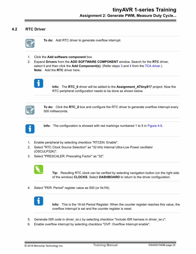
To do Add RTC driver to generate overflow interrupt
1 Click the Add software component box2 Expand Drivers from the ADD SOFTWARE COMPONENT window Search for the RTC driver
select it and then click the Add Component(s) (Refer steps 3 and 4 from the TCA driver)Note Add the RTC driver here
Info The RTC_0 driver will be added to the Assignment_ATtiny817 project Now theRTC peripheral configuration needs to be done as shown below
To do Click the RTC_0 box and configure the RTC driver to generate overflow interrupt every500 milliseconds
Info The configuration is showed with red markings numbered 1 to 5 in Figure 4-5
1 Enable peripheral by selecting checkbox RTCEN Enable2 Select RTC Clock Source Selection as 32 kHz Internal Ultra-Low Power oscillator
(OSCULP32K)3 Select PRESCALER Prescaling Factor as 32
Tip Resulting RTC clock can be verified by selecting navigation button (on the right sideof the window) CLOCKS Select DASHBOARD to return to the driver configuration
4 Select PER Period register value as 500 (or 0x1f4)
Info This is the 16-bit Period Register When the counter register reaches this value theoverflow interrupt is set and the counter register is reset
5 Generate ISR code in driver_isrc by selecting checkbox Include ISR harness in driver_isrc6 Enable overflow interrupt by selecting checkbox OVF Overflow Interrupt enable
copy 2018 Microchip Technology Inc Training Manual DS40001949B-page 26
8 Click the CPUINT and then select the checkbox CPU_SREG Global Interrupt Enable as shownin the figure belowFigure 4-7 Enable CPU_SREG
Result The RTC configuration is completed
43 TCB DriverThe peripheral TCB will be configured to capture the PWM signal to test the capture functionality
To do Add TCB driver
1 Click the Add software component box2 Expand Drivers from the ADD SOFTWARE COMPONENT window3 Search for the Timer driver select it and then click on the Add Component(s) (Refer steps 3 and
4 from the TCA driver)
Info The TIMER_0 driver will be added to the Assignment_ATtiny817 project
4 Click the TIMER_0 and then click Rename component Specify the new name asTCB_Duty_Frequency_Measure and click Rename (Refer steps 5 and 6 from the TCA driver)
copy 2018 Microchip Technology Inc Training Manual DS40001949B-page 27
Info Now the TCB peripheral configuration needs to be done for input capture mode
To do Configure the TCB driver with input capture mode to measure the duty cycle andfrequency of the given input PWM
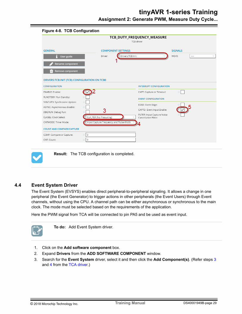
Info The configuration is shown with red markings numbered 1 to 5 in the Figure 4-8
1 Select Driver as TCBInit
Info Here by default Driver is selected as TCBinit
2 Enable peripheral by selecting checkbox ENABLE Enable3 Select the CLKSEL Clock select as CLK_PER (No Prescaling)
Info Here clock source for this peripheral is selected without prescaling This peripheraluses the systems peripheral clock CLK_PER
4 Select CNTMODE Timer mode as Input Capture Frequency and Pulse-Width measurement5 Select the checkbox CAPTEI Event Input Enable
Info Event Input is enabled as the PWM signal will be given as event input to TCB Inthe EVENT CONFIGURATION EDGE is NOT selected (unchecked) so the timer willstart counting when a positive edge is detected on the event input signal On the followingfalling edge the count value is captured The counter stops when the second rising edgeof the event input signal is detected If EDGE is selected (checked) the timer will startcounting when a negative edge is detected
Note The Event System configuration will be shown in the next section
copy 2018 Microchip Technology Inc Training Manual DS40001949B-page 28
Figure 4-8 TCB Configuration
Result The TCB configuration is completed
44 Event System DriverThe Event System (EVSYS) enables direct peripheral-to-peripheral signaling It allows a change in oneperipheral (the Event Generator) to trigger actions in other peripherals (the Event Users) through Eventchannels without using the CPU A channel path can be either asynchronous or synchronous to the mainclock The mode must be selected based on the requirements of the application
Here the PWM signal from TCA will be connected to pin PA5 and be used as event input
To do Add Event System driver
1 Click on the Add software component box2 Expand Drivers from the ADD SOFTWARE COMPONENT window3 Search for the Event System driver select it and then click the Add Component(s) (Refer steps 3
copy 2018 Microchip Technology Inc Training Manual DS40001949B-page 29
Info The EVENT_SYSTEM_0 driver will be added to the Assignment_ATtiny817project Now the EVENT_SYSTEM peripheral configuration needs to be done
To do Configure the Event System driver with event input at pin PA5 and event user as TCB
Info The EVENT_SYSTEM configuration is shown with red markings numbered 1 and 2 in the Figure 4-9
1 Click the EVENT_SYSTEM_0 box2 Select ASYNCCH0 Asynchronous Multiplexer Channel 0 as Asynchronous Event from pin PA53 Select ASYNCUSER0 Asynchronous User Selection Ch0 -TCB0 as Asynchronous Event
Channel 0
Info The Event User is TCB0 and the event input is routed through ASYNCCH0 soEVENT SYSTEM USER CONFIGURATION is selected as Asynchronous EventChannel 0Figure 4-9 EVENT SYSTEM Configuration
Result The EVENT SYSTEM configuration is completed
copy 2018 Microchip Technology Inc Training Manual DS40001949B-page 30
45 USART DriverThe peripheral USART will be configured to send the calculated duty cycle and frequency of the giveninput PWM signal
The ATtiny817 Xplained Pro contains the Embedded Debugger (EDBG) composite USB device withVirtual COM Port interface The Virtual COM Port is connected to a UART on the ATtiny817 and providesan easy way to communicate with the target application through the terminal software It offers variablebaud rate parity and stop bit settings Note that the settings on the ATtiny817 must match the settingsgiven in the terminal software
Virtual COM port connection PB2 UART TXD (ATtiny817 TX line) PB3 UART RXD (ATtiny817 RX line)
To do Add the USART driver
1 Click the Add software component box2 Expand Drivers from the ADD SOFTWARE COMPONENT window3 Search for the USART driver select it and then click the Add Component(s) (Refer steps 3 and 4
from the TCA driver)Note Add the USART driver here
Info The USART_0 driver will be added to the Assignment_ATtiny817 project Nowthe USART peripheral configuration needs to be done
To do Configure the USART driver for baud rate 9600 PB2TXD PB3RXD
Info The configuration is shown with red markings numbered 1 to 3 in the Figure 4-10
1 Under COMPONENT SETTINGS set Driver as DriversUSART_Basic and Mode as AsyncPolled Mode
2 Under SIGNALS select RXD = PB3 and TXD = PB23 Enable Transmitter by selecting checkbox TXEN Transmitter Enable If RXEN Receiver enable
copy 2018 Microchip Technology Inc Training Manual DS40001949B-page 31
Figure 4-10 USART Configuration
Result The USART configuration is completed
46 Generate Project Code DevelopmentAll the drivers needed have been added The project will now be generated and code will be added to
bull Vary duty cycle of PWM in RTC ISRbull Calculate duty cycle and frequency of given PWM signalbull Send calculated duty cycle and frequency through USART
To do Generate the project
1 Click the box (at the bottom of the window)
Info The Project Summary window lists files modified and files added to thisreconfigured project All the new and configured driver files will be listed here
copy 2018 Microchip Technology Inc Training Manual DS40001949B-page 32
Info Selecting the mainc file will create a new and empty mainc file
3 Verify that all the configured drivers are initialized in the generated project in the system_init()function
Tip src rarr driver_initc rarr system_init()
Result The project with configured drivers is generated
To do Add code to the vary duty cycle of the PWM generated by TCA in the RTC ISR
1 Open the driver_isrc file2 Define a variable above the ISR which will be changed in the ISR and initialized to 10 as initial duty
cycle is configured as 10volatile uint8_t change_duty_cycle=10
3 Add the code below inside the ISR to vary the duty cycle by 10 and roll over to 10 afterreaching 100 in ISRchange_duty_cycle+=10 if (change_duty_cycle gt100) change_duty_cycle =10 TCA0SINGLECMP0 = change_duty_cycle
Info The CMP0 register decides the duty cycle of TCA PWM
4 Press F7 to build the project (Build should finish successfully with no errors)5 Program the updated code to the device by pressing the Ctrl + Alt + F5 keys6 Connect the wire from PB0 to PB4 on the ATtiny Xplained Pro board as shown in the figure below
copy 2018 Microchip Technology Inc Training Manual DS40001949B-page 33
Figure 4-11 HW Connection
Note On the EXT1 connecter column 1 (top) corresponds to the left side PINs column andcolumn 2 (bottom) corresponds to the right side PINs column so PB0 is at column 1 (top) and PB4is at column 2 (bottom)
Info The TCA PWM output is generated on pin PB0 and the LED is connected to pinPB4 on the ATtiny Xplained Pro board So connecting PB0 and PB4 will vary the LEDintensity with the generated PWM
Result The LED is observed with varied intensity as the PWM duty cycle varies
To do Add code to calculate the duty cycle and frequency of the given PWM
The mode in TCB is configured as Input Capture Frequency and Pulse Width Measurement Mode
In this mode the timer will start counting when a positive edge is detected on the event input signal Onthe following falling edge the count value is captured The counter stops when the second rising edge of
copy 2018 Microchip Technology Inc Training Manual DS40001949B-page 34
the event input signal is detected This will also set the interrupt flag Reading the capture will clear theinterrupt flag When the capture register is read or the interrupt flag is cleared the TC is ready for a newcapture sequence
1 Open the mainc file2 Define variables to read the timer registers and store the calculated duty cycle and frequency
3 Add the code below in while(1) to calculate the duty cycle and frequencyif(TCB0INTFLAGS) TCB0INTFLAGS=1 period_after_capture = TCB0CNT pulse_width_after_capture = TCB0CCMP capture_duty = ((pulse_width_after_capture 100 )period_after_capture) if (capture_dutygt100) capture_duty=0 capture_frequency = F_CPU period_after_capture
Info TCB0INTFLAGS is set when captured values are available This flag is cleared bywriting 1 to it The period is read through TCB0CNT the pulse width is read through theTCB0CCMP register and the duty cycle is calculated in The capture frequency is inHz
To do Add code to send the calculated duty cycle and frequency of the given PWM throughthe USART
As the RTC interrupt is generated every 500 ms and the duty cycle is varied every 500 ms the code willbe added to send the calculated duty cycle and frequency after every 500 ms
1 Open the mainc file2 Define a variable to set the flag at every 500 ms and define the transmit buffer string as shown
below above main()volatile uint8_t rtc_500ms_flg=0const char tx_buf[]=ncaptured data
3 Open driver_isrc Define the rtc_500ms_flg as extern in the driver_isrc file above ISRextern uint8_t rtc_500ms_flg
4 Set the rtc_500ms_flg in RTC ISR in driver_isrcrtc_500ms_flg=1
copy 2018 Microchip Technology Inc Training Manual DS40001949B-page 35
5 In the mainc file define function send_data() above main() to convert the calculated dutycycle and frequency to string and send it through the USART as shown belowvoid send_data() uint8_t i=0 char duty_str[4]=0freq_str[10]=0tx_data[30]=0 itoa(capture_duty duty_str 10) duty cycle to ASCII ltoa(capture_frequency freq_str 10) frequency to ASCII strcat(tx_datatx_buf) tx_data=tx_buf+duty cycle string+frequency string strcat(tx_dataduty_str) strcat(tx_data ) strcat(tx_datafreq_str) strcat(tx_dataHz) while(tx_data[i] =0) check for null character USART_0_write(tx_data[i]) send data i++
6 Include the file stringh at the top of the fileinclude ltstringhgt
Info The itoa and ltoa functions defined in stringh converts the duty cycle andfrequency to ASCII The strcat function concatenates the tx_buf the duty cycle stringthe frequency string and the resulting string with the tx_data string will be sent to theterminal The USART_0_putc function writes data to the TXDATA USART registerTXDATA can only be written when the Data Register Empty Flag (DREIF inUSARTSTATUS) is set indicating that the register is empty and ready for new data
7 Add code in while(1) to call the send_data() function after every 500 msif (rtc_500ms_flg==1) rtc_500ms_flg=0 send_data()
8 Press F7 to build the project (Build should finish successfully with zero errors)9 Program the device with the updated code by selecting Debug rarr Start without Debugging
(Alternative Ctrl + Alt + F5)10 Connect the wire from PB0 to PA5 on the ATtiny Xplained Pro board as shown in the figure below
copy 2018 Microchip Technology Inc Training Manual DS40001949B-page 37
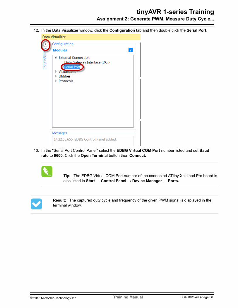
12 In the Data Visualizer window click the Configuration tab and then double click the Serial Port
13 In the Serial Port Control Panel select the EDBG Virtual COM Port number listed and set Baudrate to 9600 Click the Open Terminal button then Connect
Tip The EDBG Virtual COM Port number of the connected ATtiny Xplained Pro board isalso listed in Start rarr Control Panel rarr Device Manager rarr Ports
Result The captured duty cycle and frequency of the given PWM signal is displayed in theterminal window
copy 2018 Microchip Technology Inc Training Manual DS40001949B-page 40
5 Assignment 3 Basis of a Binary Frequency-Shift Keying SchemeThe CCL (Configurable Custom Logic) module is a programmable logic peripheral which can beconnected to the pins events or peripherals on the device It allows the user to eliminate external logicgates for simple glue logic functions
In this assignment a small CCL-based application will be developed It will blink an LED at two differentfrequencies depending on whether a button is depressed or not Two pulse trains of different frequencieswill be generated and routed to the CCL The CCL will be configured to select which of the pulse trains topass on to the output based on the state of a third input signal as shown in the figure below
Figure 5-1 CCL InputOutput Waveform
Here output = input1 when input3 is LOW and output = input2 when input3 is HIGH
The application can be the basis of a binary frequency-shift keying scheme that encodes binary data asdiscrete shifts between two frequencies
So in this applicationbull input1 is the PWM signal generated using TCA in Assignment 2bull input2 event output from PITbull input3 is button state (SW0)bull output is CCL output on pin PA7
The LED will be connected to PA7 and blink with different frequencies on button press and buttonrelease
The RTC peripheral offers two timing functions the Real-Time Counter (RTC) and a Periodic InterruptTimer (PIT) The PIT functionality can be enabled independent of the RTC functionality
By using the same clock source as the RTC function the PIT can request an interrupt or trigger an outputevent on every nth clock period n can be selected from 4 8 16 32768 Here the Event System will beconfigured to output events from the PIT The event signals from the PIT has the form of clock signalswith periods corresponding to the respective number of the RTC clock periods This application uses theevent signal corresponding to 8192 RTC clock periods The event signal from the PIT has a frequency of32 kHz8192 = 39 Hz (period approximately 250 ms)
The Assignment_ATtiny817 project will be reconfigured to add the CCL driver and edit the EventSystem and RTC driver
For this application the peripherals used arebull TCA (waveform output WO0 on PB0)bull PIT (event output)bull CCL (output PA7)
tinyAVR 1-series TrainingAssignment 3 Basis of a Binary Frequency-Shif
copy 2018 Microchip Technology Inc Training Manual DS40001949B-page 41
bull Event Systembull PB5 (SW0)
Clock detailsbull 333 MHz main clockbull PIT 32 kHz
51 CCL DriverThe Configurable Custom Logic (CCL) is a programmable logic peripheral which can be connected to thedevice pins to events or to other internal peripherals The CCL can serve as glue logic between thedevice peripherals and external devices
The CCL peripheral has one pair of Lookup Tables (LUT) Each LUT consists of three inputs a truthtable and a filteredge detector Each LUT can generate an output as a user programmable logicexpression with three inputs The output can be generated from the inputs with different combinations
In this application LUT1 will be used
bull input1 is PWM generated using TCA (WO0 of TCA)bull input2 is event output from PIT Event Source 1bull input3 is button press (SW0) Event Source 0bull output is CCL output on pin PA7
The Truth Table for the needed combination is shown in the table below IN[2] is button (SW0)
when IN[2] = 0 OUTPUT= IN[1] and when IN[2] =1 OUTPUT = IN[0]
So OUT= 0xACTable 5-1 Truth Table of LUT
IN[2] IN[1] IN[0] OUT
0 0 0 0 (LSB)
0 0 1 0
0 1 0 1
0 1 1 1
1 0 0 0
1 0 1 1
1 1 0 0
1 1 1 1
To do Add the CCL driver
1 Open the Assignment_ATtiny817 project2 In the Solution Explorer window click on the project name Assignment_ATtiny817 and then
Right Click rarr Re-Configure Atmel Start Project
tinyAVR 1-series TrainingAssignment 3 Basis of a Binary Frequency-Shif
copy 2018 Microchip Technology Inc Training Manual DS40001949B-page 42
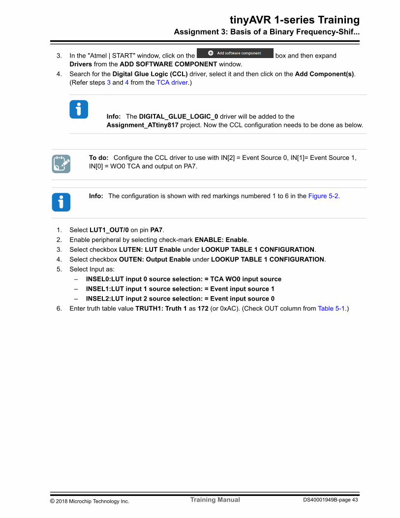
3 In the Atmel | START window click on the box and then expandDrivers from the ADD SOFTWARE COMPONENT window
4 Search for the Digital Glue Logic (CCL) driver select it and then click on the Add Component(s)(Refer steps 3 and 4 from the TCA driver)
Info The DIGITAL_GLUE_LOGIC_0 driver will be added to theAssignment_ATtiny817 project Now the CCL configuration needs to be done as below
To do Configure the CCL driver to use with IN[2] = Event Source 0 IN[1]= Event Source 1IN[0] = WO0 TCA and output on PA7
Info The configuration is shown with red markings numbered 1 to 6 in the Figure 5-2
1 Select LUT1_OUT0 on pin PA72 Enable peripheral by selecting check-mark ENABLE Enable3 Select checkbox LUTEN LUT Enable under LOOKUP TABLE 1 CONFIGURATION4 Select checkbox OUTEN Output Enable under LOOKUP TABLE 1 CONFIGURATION5 Select Input as
6 Enter truth table value TRUTH1 Truth 1 as 172 (or 0xAC) (Check OUT column from Table 5-1)
tinyAVR 1-series TrainingAssignment 3 Basis of a Binary Frequency-Shif
copy 2018 Microchip Technology Inc Training Manual DS40001949B-page 43
Figure 5-2 CCL Configuration
Result The CCL configuration is completed
52 Event System DriverThe Event System (EVSYS) enables direct peripheral-to-peripheral signaling It allows a change in oneperipheral (the Event Generator) to trigger actions in other peripherals (the Event Users) through Eventchannels without using the CPU
Here the event signal will be generated from the SW0 (PB5) push button and the PIT (Periodic InterruptTimer)
tinyAVR 1-series TrainingAssignment 3 Basis of a Binary Frequency-Shif
copy 2018 Microchip Technology Inc Training Manual DS40001949B-page 44
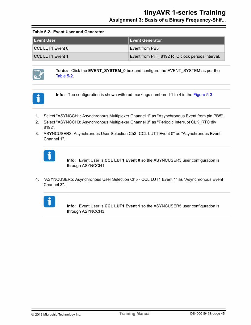
Table 5-2 Event User and Generator
Event User Event Generator
CCL LUT1 Event 0 Event from PB5
CCL LUT1 Event 1 Event from PIT 8192 RTC clock periods interval
To do Click the EVENT_SYSTEM_0 box and configure the EVENT_SYSTEM as per the Table 5-2
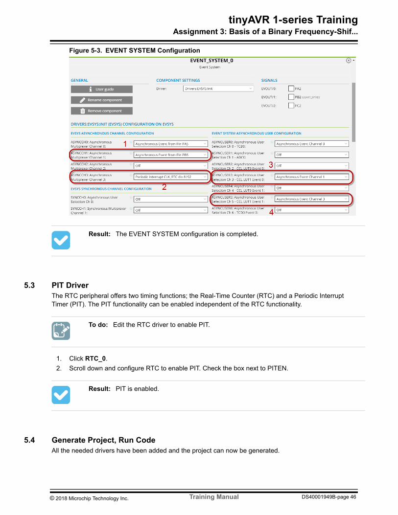
Info The configuration is shown with red markings numbered 1 to 4 in the Figure 5-3
1 Select ASYNCCH1 Asynchronous Multiplexer Channel 1 as Asynchronous Event from pin PB52 Select ASYNCCH3 Asynchronous Multiplexer Channel 3 as Periodic Interrupt CLK_RTC div
81923 ASYNCUSER3 Asynchronous User Selection Ch3 -CCL LUT1 Event 0 as Asynchronous Event
Channel 1
Info Event User is CCL LUT1 Event 0 so the ASYNCUSER3 user configuration isthrough ASYNCCH1
4 ASYNCUSER5 Asynchronous User Selection Ch5 - CCL LUT1 Event 1 as Asynchronous EventChannel 3
Info Event User is CCL LUT1 Event 1 so the ASYNCUSER5 user configuration isthrough ASYNCCH3
tinyAVR 1-series TrainingAssignment 3 Basis of a Binary Frequency-Shif
copy 2018 Microchip Technology Inc Training Manual DS40001949B-page 45
Figure 5-3 EVENT SYSTEM Configuration
Result The EVENT SYSTEM configuration is completed
53 PIT DriverThe RTC peripheral offers two timing functions the Real-Time Counter (RTC) and a Periodic InterruptTimer (PIT) The PIT functionality can be enabled independent of the RTC functionality
To do Edit the RTC driver to enable PIT
1 Click RTC_02 Scroll down and configure RTC to enable PIT Check the box next to PITEN
Result PIT is enabled
54 Generate Project Run CodeAll the needed drivers have been added and the project can now be generated
tinyAVR 1-series TrainingAssignment 3 Basis of a Binary Frequency-Shif
copy 2018 Microchip Technology Inc Training Manual DS40001949B-page 46
To do Generate the project
1 Click the box (at the bottom of the window)
Info A Project Summary window lists files modified and files added on thisreconfigured project All the new and configured driver files will be listed here
2 In the Project Summary window click OK
Info If the mainc and driver_isrc files are selected any earlier code will be overwrittenand these two files will be created as empty files
3 Verify that all the configured drivers are initialized in the generated project in folder src filedriver_initc in function system_init()
Result The project with the configured drivers is generated
To do Run the code
1 Press F7 to build the project (Build should finish successfully with no errors)2 Program the updated code to the device by selecting Debug rarr Start without Debugging3 Connect the wire from PA7 to PB4 on the ATtiny Xplained Pro board as shown in the figure below
tinyAVR 1-series TrainingAssignment 3 Basis of a Binary Frequency-Shif
copy 2018 Microchip Technology Inc Training Manual DS40001949B-page 47
Figure 5-4 HW Connection
Note On the EXT1 column 1 (top) corresponds to the left side PINs column and column 2(bottom) corresponds to the right side PINs column so PA7 and PB4 both are in column 2 (bottom)
Info The CCL output is generated on pin PA7 and the LED is connected to pin PB4 onthe ATtiny Xplained Pro board The LED blinking with different frequencies can beobserved by connecting PB4 and PA7
4 Press the push button SW0 and observe the LED release the push button and observe the LED
Result When the push button is released the LED blinks with TCA PWM that is the duty cycleis changing after every 500 ms and LED intensity varies When the push button is pressed theLED blinks with a PIT RTC_clock 8192 period interval
Info This application can be made core independent if the RTC OVF interrupt is disabled Toview the LED blinking edit the TCA driver to generate the PWM signal such that the LEDblinking is visible (Eg 12 Hz signal with 50 duty cycle)
tinyAVR 1-series TrainingAssignment 3 Basis of a Binary Frequency-Shif
copy 2018 Microchip Technology Inc Training Manual DS40001949B-page 48
6 ConclusionThis training demonstrated
bull The driver configuration through Atmel STARTbull The use of automatically generated driver functions in the code developmentbull Re-configuration of the project to edit and add drivers
You also learned
bull The different peripherals of tinyAVR 1-seriesbull How to use Event System to generate Eventbull How to use CCL to generate output
With Atmel Studio it is easy to run real-time debugging of an application and use the IO view whichprovides register view capability and allows modifying the microcontroller registers in real-time It ispossible to debug the application using various debugging methods such as
bull Breakpointsbull Single Steppingbull IO view
tinyAVR 1-series TrainingConclusion
copy 2018 Microchip Technology Inc Training Manual DS40001949B-page 49
7 Get Source Code from Atmel | STARTThe example code is available through Atmel | START which is a web-based tool that enablesconfiguration of application code through a Graphical User Interface (GUI) The code can be downloadedfor both Atmel Studio 70 and IAR Embedded Workbenchreg via the direct example code-link(s) below orthe BROWSE EXAMPLES button on the Atmel | START front page
Atmel | START web page httpmicrochipcomstart
Example Code
bull Getting Started with the tinyAVR 1-seriesndash httpstartatmelcomexampleAtmelgetting_started_with_the_tinyavr_1_series
Press User guide in Atmel | START for details and information about example projects The User guidebutton can be found in the example browser and by clicking the project name in the dashboard viewwithin the Atmel | START project configurator
Atmel Studio
Download the code as an atzip file for Atmel Studio from the example browser in Atmel | START byclicking DOWNLOAD SELECTED EXAMPLE To download the file from within Atmel | START clickEXPORT PROJECT followed by DOWNLOAD PACK
Double-click the downloaded atzip file and the project will be imported to Atmel Studio 70
IAR Embedded Workbench
For information on how to import the project in IAR Embedded Workbench open the Atmel | START userguide select Using Atmel Start Output in External Tools and IAR Embedded Workbench A link to theAtmel | START user guide can be found by clicking About from the Atmel | START front page or Help AndSupport within the project configurator both located in the upper right corner of the page
tinyAVR 1-series TrainingGet Source Code from Atmel | START
copy 2018 Microchip Technology Inc Training Manual DS40001949B-page 50
8 Revision HistoryDoc Rev Date Comments
B 022018 Added Chapter Relevant Devices and section Get code from START intothe examples readme
A 082017 Initial document release
tinyAVR 1-series TrainingRevision History
copy 2018 Microchip Technology Inc Training Manual DS40001949B-page 51
The Microchip Web Site
Microchip provides online support via our web site at httpwwwmicrochipcom This web site is used asa means to make files and information easily available to customers Accessible by using your favoriteInternet browser the web site contains the following information
bull Product Support ndash Data sheets and errata application notes and sample programs designresources userrsquos guides and hardware support documents latest software releases and archivedsoftware
bull General Technical Support ndash Frequently Asked Questions (FAQ) technical support requestsonline discussion groups Microchip consultant program member listing
bull Business of Microchip ndash Product selector and ordering guides latest Microchip press releaseslisting of seminars and events listings of Microchip sales offices distributors and factoryrepresentatives
Customer Change Notification Service
Microchiprsquos customer notification service helps keep customers current on Microchip productsSubscribers will receive e-mail notification whenever there are changes updates revisions or erratarelated to a specified product family or development tool of interest
To register access the Microchip web site at httpwwwmicrochipcom Under ldquoSupportrdquo click onldquoCustomer Change Notificationrdquo and follow the registration instructions
Customer Support
Users of Microchip products can receive assistance through several channels
bull Distributor or Representativebull Local Sales Officebull Field Application Engineer (FAE)bull Technical Support
Customers should contact their distributor representative or Field Application Engineer (FAE) for supportLocal sales offices are also available to help customers A listing of sales offices and locations is includedin the back of this document
Technical support is available through the web site at httpwwwmicrochipcomsupport
Microchip Devices Code Protection Feature
Note the following details of the code protection feature on Microchip devices
bull Microchip products meet the specification contained in their particular Microchip Data Sheetbull Microchip believes that its family of products is one of the most secure families of its kind on the
market today when used in the intended manner and under normal conditionsbull There are dishonest and possibly illegal methods used to breach the code protection feature All of
these methods to our knowledge require using the Microchip products in a manner outside theoperating specifications contained in Microchiprsquos Data Sheets Most likely the person doing so isengaged in theft of intellectual property
bull Microchip is willing to work with the customer who is concerned about the integrity of their code
tinyAVR 1-series Training
copy 2018 Microchip Technology Inc Training Manual DS40001949B-page 52
bull Neither Microchip nor any other semiconductor manufacturer can guarantee the security of theircode Code protection does not mean that we are guaranteeing the product as ldquounbreakablerdquo
Code protection is constantly evolving We at Microchip are committed to continuously improving thecode protection features of our products Attempts to break Microchiprsquos code protection feature may be aviolation of the Digital Millennium Copyright Act If such acts allow unauthorized access to your softwareor other copyrighted work you may have a right to sue for relief under that Act
Legal Notice
Information contained in this publication regarding device applications and the like is provided only foryour convenience and may be superseded by updates It is your responsibility to ensure that yourapplication meets with your specifications MICROCHIP MAKES NO REPRESENTATIONS ORWARRANTIES OF ANY KIND WHETHER EXPRESS OR IMPLIED WRITTEN OR ORAL STATUTORYOR OTHERWISE RELATED TO THE INFORMATION INCLUDING BUT NOT LIMITED TO ITSCONDITION QUALITY PERFORMANCE MERCHANTABILITY OR FITNESS FOR PURPOSEMicrochip disclaims all liability arising from this information and its use Use of Microchip devices in lifesupport andor safety applications is entirely at the buyerrsquos risk and the buyer agrees to defendindemnify and hold harmless Microchip from any and all damages claims suits or expenses resultingfrom such use No licenses are conveyed implicitly or otherwise under any Microchip intellectualproperty rights unless otherwise stated
Trademarks
The Microchip name and logo the Microchip logo AnyRate AVR AVR logo AVR Freaks BeaconThingsBitCloud CryptoMemory CryptoRF dsPIC FlashFlex flexPWR Heldo JukeBlox KeeLoq KeeLoq logoKleer LANCheck LINK MD maXStylus maXTouch MediaLB megaAVR MOST MOST logo MPLABOptoLyzer PIC picoPower PICSTART PIC32 logo Prochip Designer QTouch RightTouch SAM-BASpyNIC SST SST Logo SuperFlash tinyAVR UNIO and XMEGA are registered trademarks ofMicrochip Technology Incorporated in the USA and other countries
ClockWorks The Embedded Control Solutions Company EtherSynch Hyper Speed Control HyperLightLoad IntelliMOS mTouch Precision Edge and Quiet-Wire are registered trademarks of MicrochipTechnology Incorporated in the USA
Adjacent Key Suppression AKS Analog-for-the-Digital Age Any Capacitor AnyIn AnyOut BodyComchipKIT chipKIT logo CodeGuard CryptoAuthentication CryptoCompanion CryptoControllerdsPICDEM dsPICDEMnet Dynamic Average Matching DAM ECAN EtherGREEN In-Circuit SerialProgramming ICSP Inter-Chip Connectivity JitterBlocker KleerNet KleerNet logo Mindi MiWimotorBench MPASM MPF MPLAB Certified logo MPLIB MPLINK MultiTRAK NetDetach OmniscientCode Generation PICDEM PICDEMnet PICkit PICtail PureSilicon QMatrix RightTouch logo REALICE Ripple Blocker SAM-ICE Serial Quad IO SMART-IS SQI SuperSwitcher SuperSwitcher II TotalEndurance TSHARC USBCheck VariSense ViewSpan WiperLock Wireless DNA and ZENA aretrademarks of Microchip Technology Incorporated in the USA and other countries
SQTP is a service mark of Microchip Technology Incorporated in the USA
Silicon Storage Technology is a registered trademark of Microchip Technology Inc in other countries
GestIC is a registered trademark of Microchip Technology Germany II GmbH amp Co KG a subsidiary ofMicrochip Technology Inc in other countries
All other trademarks mentioned herein are property of their respective companies
tinyAVR 1-series Training
copy 2018 Microchip Technology Inc Training Manual DS40001949B-page 53
copy 2018 Microchip Technology Incorporated Printed in the USA All Rights Reserved
ISBN 978-1-5224-2459-8
Quality Management System Certified by DNV
ISOTS 16949Microchip received ISOTS-169492009 certification for its worldwide headquarters design and waferfabrication facilities in Chandler and Tempe Arizona Gresham Oregon and design centers in Californiaand India The Companyrsquos quality system processes and procedures are for its PICreg MCUs and dsPICreg
DSCs KEELOQreg code hopping devices Serial EEPROMs microperipherals nonvolatile memory andanalog products In addition Microchiprsquos quality system for the design and manufacture of developmentsystems is ISO 90012000 certified
tinyAVR 1-series Training
copy 2018 Microchip Technology Inc Training Manual DS40001949B-page 54
copy 2018 Microchip Technology Inc Training Manual DS40001949B-page 55
Prerequisites
Introduction
Table of Contents
1 Relevant Devices
11 tinyAVR 1-Series
2 Icon Key Identifiers
3 Assignment 1 LED TOGGLE Application
31 Atmel START Project Creation
32 Atmel START Project Overview
33 Code Development
34 Debug Application
4 Assignment 2 Generate PWM Measure Duty Cycle and Frequency
41 TCA Driver
42 RTC Driver
43 TCB Driver
44 Event System Driver
45 USART Driver
46 Generate Project Code Development
5 Assignment 3 Basis of a Binary Frequency-Shift Keying Scheme
51 CCL Driver
52 Event System Driver
53 PIT Driver
54 Generate Project Run Code
6 Conclusion
7 Get Source Code from Atmel | START
8 Revision History
The Microchip Web Site
Customer Change Notification Service
Customer Support
Microchip Devices Code Protection Feature
Legal Notice
Trademarks
Quality Management System Certified by DNV
Worldwide Sales and Service
The peripherals used to create applications are GPIO timers TCA and TCB Event System USART CCL(Configurable Custom Logic) and PIT (Periodic Interrupt Interval)
Figure 1 ATtiny817 Xplained Pro
The following topics are covered
bull Driver Configuration in Atmel STARTbull PINMUX driver configuration and check LED toggle on button pressbull Generate a PWM by using timer counter A (TCA) and implement Variable-Pulse-Width by using the
RTC interruptbull Duty cycle and frequency measurement using input capture mode of TCBbull USART configurationbull Use the Data Visualizer tool to send data to the serial terminalbull CCL (Configurable Custom Logic) A programmable logic peripheral which can be connected to the
device pins events or peripherals which allows the user to eliminate external logic gates for simpleglue logic functions Here configure CCL to generate the specific signal using the event from GPIO andtwo PWM signals
Note Solution projects for this training can be found in Atmel START rarr BROWSE EXAMPLES GettingStarted with the tinyAVRreg 1-series
tinyAVR 1-series Training
copy 2018 Microchip Technology Inc Training Manual DS40001949B-page 2
4 Assignment 2 Generate PWM Measure Duty Cycle and Frequency1941 TCA Driver1942 RTC Driver 2543 TCB Driver2744 Event System Driver2945 USART Driver3146 Generate Project Code Development 32
5 Assignment 3 Basis of a Binary Frequency-Shift Keying Scheme 4151 CCL Driver4252 Event System Driver4453 PIT Driver 4654 Generate Project Run Code46
6 Conclusion49
7 Get Source Code from Atmel | START 50
8 Revision History51
The Microchip Web Site 52
Customer Change Notification Service52
Customer Support 52
Microchip Devices Code Protection Feature 52
Legal Notice53
Trademarks 53
copy 2018 Microchip Technology Inc Training Manual DS40001949B-page 3
Quality Management System Certified by DNV54
Worldwide Sales and Service55
tinyAVR 1-series Training
copy 2018 Microchip Technology Inc Training Manual DS40001949B-page 4
1 Relevant DevicesThis chapter lists the relevant devices for this document
11 tinyAVR 1-SeriesThe figure below shows the tinyAVR 1-series devices illustrating pin count variants and memory sizes
bull Vertical migration upwards is possible without code modification as these devices are pincompatible and provide the same or more features Downward migration may require codemodification due to fewer available instances of some peripherals
bull Horizontal migration to the left reduces the pin count and therefore the available features
Figure 1-1 tinyAVRreg 1-Series Device Overview
32KB
16KB
8KB
4KB
2KB
8 14 20 24Pins
Flash
ATtiny816 ATtiny817ATtiny814
ATtiny417
ATtiny1616 ATtiny1617
ATtiny414 ATtiny416ATtiny412
ATtiny214ATtiny212
ATtiny1614
Devices with different Flash memory size typically also have different SRAM and EEPROM
tinyAVR 1-series TrainingRelevant Devices
copy 2018 Microchip Technology Inc Training Manual DS40001949B-page 5
2 Icon Key IdentifiersThe following icons are used in this document to identify the different assignment sections and to reducethe complexity
Info Delivers contextual information about a specific topic
Tip Highlights useful tips and techniques
To do Highlights objectives to be completed
Result Highlights the expected result of an assignment step
WARNING Indicates important information
Execute Highlights actions to be executed out of the target when necessary
tinyAVR 1-series TrainingIcon Key Identifiers
copy 2018 Microchip Technology Inc Training Manual DS40001949B-page 6
3 Assignment 1 LED TOGGLE ApplicationAn application will be developed that controls the LED using the push-button on the board The LED willbe OFF on pressing the button default state is LED ON
A project will be configured in Atmel START using PINMUX driver configuration and clock configurationfollowed by generation of the corresponding Atmel Studio 7 project
The code will be developed in Atmel Studio 7 using PINMUX driver functions generated by Atmel STARTconfiguration
On the ATtiny817 Xplained Pro board LED0 is connected to pin PB4 and the push-button (SW0) isconnected to pin PB5
For applicationbull Peripherals used GPIO (PB4 PB5)bull Clock 333 MHz
31 Atmel START Project CreationConfigure the PINMUX driver and CLOCK in Atmel START and create the project
To do Create a new Atmel START Project
1 Open Atmel Studio2 Select File rarr New rarr Atmel Start Project3 The CREATE NEW PROJECT window appears within Atmel Studio 7 In the Filter on device
text box enter 817X then select ATtiny817 Xplained Pro from the list and verify that ATtiny817Xplained Pro is highlighted then click on CREATE NEW PROJECT as shown belowFigure 3-1 CREATE NEW PROJECT
Info Now the MY SOFTWARE COMPONENTS window appears
tinyAVR 1-series TrainingAssignment 1 LED TOGGLE Application
copy 2018 Microchip Technology Inc Training Manual DS40001949B-page 7
4 In MY SOFTWARE COMPONENTS windowndash 1 Click on MY PROJECTndash 2 Select Rename Component
Figure 3-2 Rename Component
Info Now the RENAME COMPONENT window will be displayed
5 In the RENAME COMPONENT window specify the new project name as Assignment_ATtiny817and select Rename
6 Now for PINMUX configuration click on the navigation tab on the left side of the window
Info The PINMUX configurator displays an illustration of the device package selected Itshows which pins are currently used by different peripherals The GPIO pins can beconfigured here
Info Here PB4 is configured as LED0 and PB5 as SW0 Configuration is shown withfour steps (the red markings numbered 1 2 3 and 4 in the figure below)
7 Configuration of PB4ndash 1 Click on PB4ndash 2 Enter User label as LED0
tinyAVR 1-series TrainingAssignment 1 LED TOGGLE Application
copy 2018 Microchip Technology Inc Training Manual DS40001949B-page 8
ndash 3 Enter Pin mode as Digital outputndash 4 Select Initial level as Low
Figure 3-3 PINMUX Configuration LED0
8 Configuration of PB5ndash 1 Click on PB5ndash 2 Enter User label as SW0ndash 3 Enter Pin mode as Digital inputndash 4 Select Initial level as Pull-up
Figure 3-4 PINMUX Configuration SW0
Info Technical documents related to the ATtiny817 Xplained Pro can be downloadedfrom within Atmel Studio from the page ATtiny817 Xplained Pro rarr TechnicalDocumentation The ATtiny817 Xplained Pro page is displayed once the ATtiny817Xplained Pro board is connected to the computer
tinyAVR 1-series TrainingAssignment 1 LED TOGGLE Application
copy 2018 Microchip Technology Inc Training Manual DS40001949B-page 9
9 CLOCK CONFIGURATOR Now for clock configuration click on the navigation tab on theleft side of the window
Info Now the CLOCK CONFIGURATOR window will be displayed It consists ofoscillators and clock sources of different types The required clock source can be selectedand the calculated output frequency will be displayed
ndash The OSCILLATORS section displays the oscillators available for the selected device Theoscillator parameters can be configured by selecting Settings Dialog (cog wheel icon)
ndash The SOURCES section is used to configure the clock frequency by selecting input signal andchanging the multiplier
10 Click on the Settings Dialog (cog wheel icon) to view the default Main clock settings fromSOURCES as shown in the figure below
Info The CLOCK SETTING window will be displayed
Figure 3-5 CLOCK SETTING
Info For this application the default clock settings are kept as they are Here the MainClock source is 20 MHz OSC the prescaler is divided by 6 The resulting CPU clock
frequency is 333 MHz The click on the question mark next to each configuration will be directed to the data sheet description of individual bit settings
11 Click Close in the CLOCK SETTING window
12 Now click on the GENERATE PROJECT button 13 Select the desired path where the project should be stored as shown in the figure below and then
click OK
tinyAVR 1-series TrainingAssignment 1 LED TOGGLE Application
copy 2018 Microchip Technology Inc Training Manual DS40001949B-page 10
Figure 3-6 Project Importer Window
Result An Atmel START project has been created
32 Atmel START Project OverviewThe project configured in Atmel START generates peripheral driver functions and files as well as a main()function that initializes all the drivers
About folders and files generated by Atmel START
bull The Config folder contains clock configuration F_CPU is defined in clock_confighbull The driver header and source files are to be found in the src and include foldersbull The atmel_start_pinsh file in the include folder contains the PINMUX driver functionsbull The utils folder contains files that define some functions to be commonly used by the drivers and
applicationbull In the atmel_startc file the function atmel_start_init() initializes the MCU the drivers and
the middleware in the projectbull The driver_isrc file contains ISR if the interrupts are enabled in the configuration of the project
tinyAVR 1-series TrainingAssignment 1 LED TOGGLE Application
copy 2018 Microchip Technology Inc Training Manual DS40001949B-page 11
To do Get an overview of the Atmel START project
1 In the Assignment_ATtiny817 project double-click the mainc file from the Solution Explorerwindow
2 Select the atmel_start_init function then RIGHT CLICK rarr Goto Implementation Repeatthe procedure for the system_init() function to direct to the function definition
Info The mcu_init() function enables the internal pull-up resistor on all pins to reducethe power consumption All driver initialization functions are called from thesystem_init() function Also the LED0 and SW0 port pins are configured to outputand input mode with initial pin status
3 Go to the implementation of CLKCTRL_init() and observe that the default clock settings arecommented out
Tip driver_initc rarr system_init() rarr CLKCTRL_init()
tinyAVR 1-series TrainingAssignment 1 LED TOGGLE Application
copy 2018 Microchip Technology Inc Training Manual DS40001949B-page 12
Info If the non-default clock settings are selected in Atmel START it will be reflected inCLKCTRL_init()
4 Open atmel_start_pinsh and click on the down arrow as shown in the figure below to open the listof functions defined in this file Observe that many useful GPIO functions have been generated
Result The Atmel START project overview is completed
33 Code DevelopmentOn the ATtiny817 Xplained Pro board the behavior of the pins associated with LED0 and SW0 is asfollows
Table 3-1 Behavior of the Pins Associated with LED0 and SW0
SW0LED0 Status Pin Level
SW0 Button depressed PB5 LOW
SW0 Button released (default status) PB5 HIGH
LED0 ON PB4 LOW
LED0 OFF PB4 HIGH
To do Write a code that turns the LED OFF when the button is depressed and turns it back toON when it is released
1 Open the mainc file in the Assignment_ATtiny817 project2 Insert the code in while(1) to read the SW0 status and to configure LED0 status as mentioned
belowndash When the button (SW0) is depressed LED0 is OFF (LED0 pin level = high)
tinyAVR 1-series TrainingAssignment 1 LED TOGGLE Application
copy 2018 Microchip Technology Inc Training Manual DS40001949B-page 13
ndash When the button (SW0) is released LED0 is ON (LED0 pin level = low)
if(SW0_get_level()) (SW0)button pressed PB5 is low LED0_set_level(true) LED0 is turned OFF PB4 is high while(SW0_get_level()) wait till (SW0)button release LED0_set_level(false) (SW0)button released LED0 is turned ON PB4 is low
Info The SW0_get_level() function returns the SW0 pin status TheLED0_set_level(true) function sets the LED0 level high
3 After the code completion press F7 to build the solution The build should finish successfully withno errors
Result The code should look like the image shown below
Figure 3-7 Assignment 1 Code
34 Debug Application
To do Debug the application Assignment1 LED Toggle
1 Power the ATtiny817 Xplained Pro board by connecting it with Micro-USB cable to the computer2 Select Debug rarr Start Debugging and Break (or Alt + F5) Follow the prompts to select the
ATtiny817 Xplained Pro EDBG as programmerdebugger and press Alt + F5 again
tinyAVR 1-series TrainingAssignment 1 LED TOGGLE Application
copy 2018 Microchip Technology Inc Training Manual DS40001949B-page 14
Figure 3-8 Debug Menu
Info If the firmware version of the on-board debugger is older than the one in the AtmelStudio installation it will be asked to upgrade the firmware
tinyAVR 1-series TrainingAssignment 1 LED TOGGLE Application
copy 2018 Microchip Technology Inc Training Manual DS40001949B-page 15
Figure 3-9 Firmware Upgrade
Select Upgrade When the progress bar is complete select Close Now start the debugging byselecting Debug rarr Start Debugging and Break (Alternative Alt+F5)
Result The debugger is started and breaks in main() Debugging can now be started
3 Click on the margin to insert the breakpoint as shown in the figure belowFigure 3-10 Breakpoint Inserted
4 Run to breakpoint by clicking Debug rarr Continue
tinyAVR 1-series TrainingAssignment 1 LED TOGGLE Application
copy 2018 Microchip Technology Inc Training Manual DS40001949B-page 16
Tip The play button located on the toolbar close to the top of the Atmel Studio 7window can be used to start or continue debugging Keyboard shortcut F5 can also beused
5 Press the push button SW0 and observe that execution stops at the breakpoint6 To check the status of all the PORTB pins open the IO view window by selecting Debug rarr
Windows rarr IO and click on the PORTB register group as shown in the image below
Info In the IO view the status of all the peripherals can be observed Pin status isindicated for PB0 to PB7 from right to left under the Bits column in the OUT register Asshown in the image below the level of pin PB4 (LED0) is high as a filled squarecorresponds to bit status 1 An empty square corresponds to bit status 0
Figure 3-11 IO View
tinyAVR 1-series TrainingAssignment 1 LED TOGGLE Application
copy 2018 Microchip Technology Inc Training Manual DS40001949B-page 17
7 Do single step debugging by pressing F10 and observe the status of PB4
Info PB7 is the left most bit and PB0 is the right most bit
8 Remove a breakpoint by clicking on it and run the code by clicking Debug rarr Continue or select
9 Stop debugging by selecting 10 Press the push-button SW0 and observe the LED0 toggle
Info The application is programmed successfully to the ATtiny817 Xplained Pro board
tinyAVR 1-series TrainingAssignment 1 LED TOGGLE Application
copy 2018 Microchip Technology Inc Training Manual DS40001949B-page 18
4 Assignment 2 Generate PWM Measure Duty Cycle and FrequencyThe ATtiny817 has two 16-bit TimerCounter instances TCA and TCB and one 12-bit TimerCounterTCD
Here an application will be developed to generate the PWM using the TCA The RTC interrupt will beused to vary the duty cycle of the PWM
The TCA waveform output will be used as input to the TCB through the Event System and the inputcapture mode of the TCB will be used to measure the duty cycle and the frequency of the waveform Themeasured data will be sent to the terminal through the USART
Single-Slope PWM Generation mode will be used for TCA Here the period is controlled by the PERregister while the values of the CMPn compare register controls the duty cycle of the waveformgenerated (WG) output the WOn The counter value is compared to the CMPx registers and the PERregister to set the waveform period or pulse width
The Atmel START project from Assignment1 LED TOGGLE (Assignment_ATtiny817) will bereconfigured to add drivers for TCA TCB Event System RTC and USART
For the application the peripherals used arebull TCA (waveform output WO0 on PB0)bull TCBbull Event System (event input from pin PA5)bull RTCbull USART
Clockbull 333 MHz main clockbull 1 kHz RTC clock
41 TCA Driver
To do Add TCA driver to generate PWM signal
1 Open the Assignment1LED TOGGLE project Assignment_ATtiny8172 In the Solution Explorer window click on the project name Assignment_ATtiny817 and then
Right Click rarr Re-Configure Atmel Start Project as shown below
copy 2018 Microchip Technology Inc Training Manual DS40001949B-page 21
Figure 4-3 Rename TCA
6 Specify the new name as TCA_PWM and click Rename
Info Now the TCA peripheral configuration needs to be done to generate the PWMsignal This is shown below
To do Configure the TCA driver to generate PWM (W0) on pin PB0 frequency 32 kHzinitial duty cycle 10
Info The configuration is shown with red markings numbered 1 to 8 in Figure 4-4
1 Select Driver as TCAInit and mode as TCA Normal Mode
Info Here by default Driver is selected as TCAinit and mode is selected as Normalmode This timer has two modes Normal mode (one 16-bit timercounter) and SplitMode In the Split Mode the 16-bit timercounter acts as two separate 8-bit timers eachwith three compare channels for PWM generation
copy 2018 Microchip Technology Inc Training Manual DS40001949B-page 22
tip To verify the WO0 output pin of the TCA refer the data sheet section IOMultiplexing and Considerations Click on the question mark next to any configuration
and go to section IO Multiplexing and Considerations to check the TCA WO0 pin
3 Enable the peripheral by selecting the check-mark of ENABLE Module Enable4 Select clock frequency for the timercounter as System Clock
Info Here by default it has been selected as System Clock (with no prescaler)
5 Enter the PER Period register value as 100 (or 0x64)
Info It contains 16-bit TOP value in the timercounter It decides the PWM frequency
6 Select the check-mark CMP0EN to get the PORT output settings for WO0 output7 Enter CMP0 Compare Register 0 value as 10 (or 0xa)
Info This register is continuously compared to the counter value of the timer Normallythe outputs from the comparators are then used for generating waveforms This registerdecides the duty cycle of PWM Initial duty cycle has been selected as 10 (0xa)Waveform output WO0 is required so Compare Channel 0 is configured here
8 Select WGMMODE waveform generation mode as Single Slope PWM
Info The waveform generation mode controls the counting sequence of the counterTOP value UPDATE condition interrupt condition and type of waveform that isgenerated In this Single Slope PWM mode the period is controlled by TCAPER whilethe values of TCACMPn control the duty cycle of the WG output The single-slope PWMfrequency (fPWM_SS) depends on the period setting (TCAPER) the systems peripheralclock frequency fCLK_PER and the TCA clock prescaler (CLKSEL clock selection) It is
calculated by the following equation fPWM_SS = _ sdot + 1 Here N = 1 PER =100
copy 2018 Microchip Technology Inc Training Manual DS40001949B-page 24
42 RTC Driver
To do Add RTC driver to generate overflow interrupt
1 Click the Add software component box2 Expand Drivers from the ADD SOFTWARE COMPONENT window Search for the RTC driver
select it and then click the Add Component(s) (Refer steps 3 and 4 from the TCA driver)Note Add the RTC driver here
Info The RTC_0 driver will be added to the Assignment_ATtiny817 project Now theRTC peripheral configuration needs to be done as shown below
To do Click the RTC_0 box and configure the RTC driver to generate overflow interrupt every500 milliseconds
Info The configuration is showed with red markings numbered 1 to 5 in Figure 4-5
1 Enable peripheral by selecting checkbox RTCEN Enable2 Select RTC Clock Source Selection as 32 kHz Internal Ultra-Low Power oscillator
(OSCULP32K)3 Select PRESCALER Prescaling Factor as 32
Tip Resulting RTC clock can be verified by selecting navigation button (on the right sideof the window) CLOCKS Select DASHBOARD to return to the driver configuration
4 Select PER Period register value as 500 (or 0x1f4)
Info This is the 16-bit Period Register When the counter register reaches this value theoverflow interrupt is set and the counter register is reset
5 Generate ISR code in driver_isrc by selecting checkbox Include ISR harness in driver_isrc6 Enable overflow interrupt by selecting checkbox OVF Overflow Interrupt enable
copy 2018 Microchip Technology Inc Training Manual DS40001949B-page 26
8 Click the CPUINT and then select the checkbox CPU_SREG Global Interrupt Enable as shownin the figure belowFigure 4-7 Enable CPU_SREG
Result The RTC configuration is completed
43 TCB DriverThe peripheral TCB will be configured to capture the PWM signal to test the capture functionality
To do Add TCB driver
1 Click the Add software component box2 Expand Drivers from the ADD SOFTWARE COMPONENT window3 Search for the Timer driver select it and then click on the Add Component(s) (Refer steps 3 and
4 from the TCA driver)
Info The TIMER_0 driver will be added to the Assignment_ATtiny817 project
4 Click the TIMER_0 and then click Rename component Specify the new name asTCB_Duty_Frequency_Measure and click Rename (Refer steps 5 and 6 from the TCA driver)
copy 2018 Microchip Technology Inc Training Manual DS40001949B-page 27
Info Now the TCB peripheral configuration needs to be done for input capture mode
To do Configure the TCB driver with input capture mode to measure the duty cycle andfrequency of the given input PWM
Info The configuration is shown with red markings numbered 1 to 5 in the Figure 4-8
1 Select Driver as TCBInit
Info Here by default Driver is selected as TCBinit
2 Enable peripheral by selecting checkbox ENABLE Enable3 Select the CLKSEL Clock select as CLK_PER (No Prescaling)
Info Here clock source for this peripheral is selected without prescaling This peripheraluses the systems peripheral clock CLK_PER
4 Select CNTMODE Timer mode as Input Capture Frequency and Pulse-Width measurement5 Select the checkbox CAPTEI Event Input Enable
Info Event Input is enabled as the PWM signal will be given as event input to TCB Inthe EVENT CONFIGURATION EDGE is NOT selected (unchecked) so the timer willstart counting when a positive edge is detected on the event input signal On the followingfalling edge the count value is captured The counter stops when the second rising edgeof the event input signal is detected If EDGE is selected (checked) the timer will startcounting when a negative edge is detected
Note The Event System configuration will be shown in the next section
copy 2018 Microchip Technology Inc Training Manual DS40001949B-page 28
Figure 4-8 TCB Configuration
Result The TCB configuration is completed
44 Event System DriverThe Event System (EVSYS) enables direct peripheral-to-peripheral signaling It allows a change in oneperipheral (the Event Generator) to trigger actions in other peripherals (the Event Users) through Eventchannels without using the CPU A channel path can be either asynchronous or synchronous to the mainclock The mode must be selected based on the requirements of the application
Here the PWM signal from TCA will be connected to pin PA5 and be used as event input
To do Add Event System driver
1 Click on the Add software component box2 Expand Drivers from the ADD SOFTWARE COMPONENT window3 Search for the Event System driver select it and then click the Add Component(s) (Refer steps 3
copy 2018 Microchip Technology Inc Training Manual DS40001949B-page 29
Info The EVENT_SYSTEM_0 driver will be added to the Assignment_ATtiny817project Now the EVENT_SYSTEM peripheral configuration needs to be done
To do Configure the Event System driver with event input at pin PA5 and event user as TCB
Info The EVENT_SYSTEM configuration is shown with red markings numbered 1 and 2 in the Figure 4-9
1 Click the EVENT_SYSTEM_0 box2 Select ASYNCCH0 Asynchronous Multiplexer Channel 0 as Asynchronous Event from pin PA53 Select ASYNCUSER0 Asynchronous User Selection Ch0 -TCB0 as Asynchronous Event
Channel 0
Info The Event User is TCB0 and the event input is routed through ASYNCCH0 soEVENT SYSTEM USER CONFIGURATION is selected as Asynchronous EventChannel 0Figure 4-9 EVENT SYSTEM Configuration
Result The EVENT SYSTEM configuration is completed
copy 2018 Microchip Technology Inc Training Manual DS40001949B-page 30
45 USART DriverThe peripheral USART will be configured to send the calculated duty cycle and frequency of the giveninput PWM signal
The ATtiny817 Xplained Pro contains the Embedded Debugger (EDBG) composite USB device withVirtual COM Port interface The Virtual COM Port is connected to a UART on the ATtiny817 and providesan easy way to communicate with the target application through the terminal software It offers variablebaud rate parity and stop bit settings Note that the settings on the ATtiny817 must match the settingsgiven in the terminal software
Virtual COM port connection PB2 UART TXD (ATtiny817 TX line) PB3 UART RXD (ATtiny817 RX line)
To do Add the USART driver
1 Click the Add software component box2 Expand Drivers from the ADD SOFTWARE COMPONENT window3 Search for the USART driver select it and then click the Add Component(s) (Refer steps 3 and 4
from the TCA driver)Note Add the USART driver here
Info The USART_0 driver will be added to the Assignment_ATtiny817 project Nowthe USART peripheral configuration needs to be done
To do Configure the USART driver for baud rate 9600 PB2TXD PB3RXD
Info The configuration is shown with red markings numbered 1 to 3 in the Figure 4-10
1 Under COMPONENT SETTINGS set Driver as DriversUSART_Basic and Mode as AsyncPolled Mode
2 Under SIGNALS select RXD = PB3 and TXD = PB23 Enable Transmitter by selecting checkbox TXEN Transmitter Enable If RXEN Receiver enable
copy 2018 Microchip Technology Inc Training Manual DS40001949B-page 31
Figure 4-10 USART Configuration
Result The USART configuration is completed
46 Generate Project Code DevelopmentAll the drivers needed have been added The project will now be generated and code will be added to
bull Vary duty cycle of PWM in RTC ISRbull Calculate duty cycle and frequency of given PWM signalbull Send calculated duty cycle and frequency through USART
To do Generate the project
1 Click the box (at the bottom of the window)
Info The Project Summary window lists files modified and files added to thisreconfigured project All the new and configured driver files will be listed here
copy 2018 Microchip Technology Inc Training Manual DS40001949B-page 32
Info Selecting the mainc file will create a new and empty mainc file
3 Verify that all the configured drivers are initialized in the generated project in the system_init()function
Tip src rarr driver_initc rarr system_init()
Result The project with configured drivers is generated
To do Add code to the vary duty cycle of the PWM generated by TCA in the RTC ISR
1 Open the driver_isrc file2 Define a variable above the ISR which will be changed in the ISR and initialized to 10 as initial duty
cycle is configured as 10volatile uint8_t change_duty_cycle=10
3 Add the code below inside the ISR to vary the duty cycle by 10 and roll over to 10 afterreaching 100 in ISRchange_duty_cycle+=10 if (change_duty_cycle gt100) change_duty_cycle =10 TCA0SINGLECMP0 = change_duty_cycle
Info The CMP0 register decides the duty cycle of TCA PWM
4 Press F7 to build the project (Build should finish successfully with no errors)5 Program the updated code to the device by pressing the Ctrl + Alt + F5 keys6 Connect the wire from PB0 to PB4 on the ATtiny Xplained Pro board as shown in the figure below
copy 2018 Microchip Technology Inc Training Manual DS40001949B-page 33
Figure 4-11 HW Connection
Note On the EXT1 connecter column 1 (top) corresponds to the left side PINs column andcolumn 2 (bottom) corresponds to the right side PINs column so PB0 is at column 1 (top) and PB4is at column 2 (bottom)
Info The TCA PWM output is generated on pin PB0 and the LED is connected to pinPB4 on the ATtiny Xplained Pro board So connecting PB0 and PB4 will vary the LEDintensity with the generated PWM
Result The LED is observed with varied intensity as the PWM duty cycle varies
To do Add code to calculate the duty cycle and frequency of the given PWM
The mode in TCB is configured as Input Capture Frequency and Pulse Width Measurement Mode
In this mode the timer will start counting when a positive edge is detected on the event input signal Onthe following falling edge the count value is captured The counter stops when the second rising edge of
copy 2018 Microchip Technology Inc Training Manual DS40001949B-page 34
the event input signal is detected This will also set the interrupt flag Reading the capture will clear theinterrupt flag When the capture register is read or the interrupt flag is cleared the TC is ready for a newcapture sequence
1 Open the mainc file2 Define variables to read the timer registers and store the calculated duty cycle and frequency
3 Add the code below in while(1) to calculate the duty cycle and frequencyif(TCB0INTFLAGS) TCB0INTFLAGS=1 period_after_capture = TCB0CNT pulse_width_after_capture = TCB0CCMP capture_duty = ((pulse_width_after_capture 100 )period_after_capture) if (capture_dutygt100) capture_duty=0 capture_frequency = F_CPU period_after_capture
Info TCB0INTFLAGS is set when captured values are available This flag is cleared bywriting 1 to it The period is read through TCB0CNT the pulse width is read through theTCB0CCMP register and the duty cycle is calculated in The capture frequency is inHz
To do Add code to send the calculated duty cycle and frequency of the given PWM throughthe USART
As the RTC interrupt is generated every 500 ms and the duty cycle is varied every 500 ms the code willbe added to send the calculated duty cycle and frequency after every 500 ms
1 Open the mainc file2 Define a variable to set the flag at every 500 ms and define the transmit buffer string as shown
below above main()volatile uint8_t rtc_500ms_flg=0const char tx_buf[]=ncaptured data
3 Open driver_isrc Define the rtc_500ms_flg as extern in the driver_isrc file above ISRextern uint8_t rtc_500ms_flg
4 Set the rtc_500ms_flg in RTC ISR in driver_isrcrtc_500ms_flg=1
copy 2018 Microchip Technology Inc Training Manual DS40001949B-page 35
5 In the mainc file define function send_data() above main() to convert the calculated dutycycle and frequency to string and send it through the USART as shown belowvoid send_data() uint8_t i=0 char duty_str[4]=0freq_str[10]=0tx_data[30]=0 itoa(capture_duty duty_str 10) duty cycle to ASCII ltoa(capture_frequency freq_str 10) frequency to ASCII strcat(tx_datatx_buf) tx_data=tx_buf+duty cycle string+frequency string strcat(tx_dataduty_str) strcat(tx_data ) strcat(tx_datafreq_str) strcat(tx_dataHz) while(tx_data[i] =0) check for null character USART_0_write(tx_data[i]) send data i++
6 Include the file stringh at the top of the fileinclude ltstringhgt
Info The itoa and ltoa functions defined in stringh converts the duty cycle andfrequency to ASCII The strcat function concatenates the tx_buf the duty cycle stringthe frequency string and the resulting string with the tx_data string will be sent to theterminal The USART_0_putc function writes data to the TXDATA USART registerTXDATA can only be written when the Data Register Empty Flag (DREIF inUSARTSTATUS) is set indicating that the register is empty and ready for new data
7 Add code in while(1) to call the send_data() function after every 500 msif (rtc_500ms_flg==1) rtc_500ms_flg=0 send_data()
8 Press F7 to build the project (Build should finish successfully with zero errors)9 Program the device with the updated code by selecting Debug rarr Start without Debugging
(Alternative Ctrl + Alt + F5)10 Connect the wire from PB0 to PA5 on the ATtiny Xplained Pro board as shown in the figure below
copy 2018 Microchip Technology Inc Training Manual DS40001949B-page 37
12 In the Data Visualizer window click the Configuration tab and then double click the Serial Port
13 In the Serial Port Control Panel select the EDBG Virtual COM Port number listed and set Baudrate to 9600 Click the Open Terminal button then Connect
Tip The EDBG Virtual COM Port number of the connected ATtiny Xplained Pro board isalso listed in Start rarr Control Panel rarr Device Manager rarr Ports
Result The captured duty cycle and frequency of the given PWM signal is displayed in theterminal window
copy 2018 Microchip Technology Inc Training Manual DS40001949B-page 40
5 Assignment 3 Basis of a Binary Frequency-Shift Keying SchemeThe CCL (Configurable Custom Logic) module is a programmable logic peripheral which can beconnected to the pins events or peripherals on the device It allows the user to eliminate external logicgates for simple glue logic functions
In this assignment a small CCL-based application will be developed It will blink an LED at two differentfrequencies depending on whether a button is depressed or not Two pulse trains of different frequencieswill be generated and routed to the CCL The CCL will be configured to select which of the pulse trains topass on to the output based on the state of a third input signal as shown in the figure below
Figure 5-1 CCL InputOutput Waveform
Here output = input1 when input3 is LOW and output = input2 when input3 is HIGH
The application can be the basis of a binary frequency-shift keying scheme that encodes binary data asdiscrete shifts between two frequencies
So in this applicationbull input1 is the PWM signal generated using TCA in Assignment 2bull input2 event output from PITbull input3 is button state (SW0)bull output is CCL output on pin PA7
The LED will be connected to PA7 and blink with different frequencies on button press and buttonrelease
The RTC peripheral offers two timing functions the Real-Time Counter (RTC) and a Periodic InterruptTimer (PIT) The PIT functionality can be enabled independent of the RTC functionality
By using the same clock source as the RTC function the PIT can request an interrupt or trigger an outputevent on every nth clock period n can be selected from 4 8 16 32768 Here the Event System will beconfigured to output events from the PIT The event signals from the PIT has the form of clock signalswith periods corresponding to the respective number of the RTC clock periods This application uses theevent signal corresponding to 8192 RTC clock periods The event signal from the PIT has a frequency of32 kHz8192 = 39 Hz (period approximately 250 ms)
The Assignment_ATtiny817 project will be reconfigured to add the CCL driver and edit the EventSystem and RTC driver
For this application the peripherals used arebull TCA (waveform output WO0 on PB0)bull PIT (event output)bull CCL (output PA7)
tinyAVR 1-series TrainingAssignment 3 Basis of a Binary Frequency-Shif
copy 2018 Microchip Technology Inc Training Manual DS40001949B-page 41
bull Event Systembull PB5 (SW0)
Clock detailsbull 333 MHz main clockbull PIT 32 kHz
51 CCL DriverThe Configurable Custom Logic (CCL) is a programmable logic peripheral which can be connected to thedevice pins to events or to other internal peripherals The CCL can serve as glue logic between thedevice peripherals and external devices
The CCL peripheral has one pair of Lookup Tables (LUT) Each LUT consists of three inputs a truthtable and a filteredge detector Each LUT can generate an output as a user programmable logicexpression with three inputs The output can be generated from the inputs with different combinations
In this application LUT1 will be used
bull input1 is PWM generated using TCA (WO0 of TCA)bull input2 is event output from PIT Event Source 1bull input3 is button press (SW0) Event Source 0bull output is CCL output on pin PA7
The Truth Table for the needed combination is shown in the table below IN[2] is button (SW0)
when IN[2] = 0 OUTPUT= IN[1] and when IN[2] =1 OUTPUT = IN[0]
So OUT= 0xACTable 5-1 Truth Table of LUT
IN[2] IN[1] IN[0] OUT
0 0 0 0 (LSB)
0 0 1 0
0 1 0 1
0 1 1 1
1 0 0 0
1 0 1 1
1 1 0 0
1 1 1 1
To do Add the CCL driver
1 Open the Assignment_ATtiny817 project2 In the Solution Explorer window click on the project name Assignment_ATtiny817 and then
Right Click rarr Re-Configure Atmel Start Project
tinyAVR 1-series TrainingAssignment 3 Basis of a Binary Frequency-Shif
copy 2018 Microchip Technology Inc Training Manual DS40001949B-page 42
3 In the Atmel | START window click on the box and then expandDrivers from the ADD SOFTWARE COMPONENT window
4 Search for the Digital Glue Logic (CCL) driver select it and then click on the Add Component(s)(Refer steps 3 and 4 from the TCA driver)
Info The DIGITAL_GLUE_LOGIC_0 driver will be added to theAssignment_ATtiny817 project Now the CCL configuration needs to be done as below
To do Configure the CCL driver to use with IN[2] = Event Source 0 IN[1]= Event Source 1IN[0] = WO0 TCA and output on PA7
Info The configuration is shown with red markings numbered 1 to 6 in the Figure 5-2
1 Select LUT1_OUT0 on pin PA72 Enable peripheral by selecting check-mark ENABLE Enable3 Select checkbox LUTEN LUT Enable under LOOKUP TABLE 1 CONFIGURATION4 Select checkbox OUTEN Output Enable under LOOKUP TABLE 1 CONFIGURATION5 Select Input as
6 Enter truth table value TRUTH1 Truth 1 as 172 (or 0xAC) (Check OUT column from Table 5-1)
tinyAVR 1-series TrainingAssignment 3 Basis of a Binary Frequency-Shif
copy 2018 Microchip Technology Inc Training Manual DS40001949B-page 43
Figure 5-2 CCL Configuration
Result The CCL configuration is completed
52 Event System DriverThe Event System (EVSYS) enables direct peripheral-to-peripheral signaling It allows a change in oneperipheral (the Event Generator) to trigger actions in other peripherals (the Event Users) through Eventchannels without using the CPU
Here the event signal will be generated from the SW0 (PB5) push button and the PIT (Periodic InterruptTimer)
tinyAVR 1-series TrainingAssignment 3 Basis of a Binary Frequency-Shif
copy 2018 Microchip Technology Inc Training Manual DS40001949B-page 44
Table 5-2 Event User and Generator
Event User Event Generator
CCL LUT1 Event 0 Event from PB5
CCL LUT1 Event 1 Event from PIT 8192 RTC clock periods interval
To do Click the EVENT_SYSTEM_0 box and configure the EVENT_SYSTEM as per the Table 5-2
Info The configuration is shown with red markings numbered 1 to 4 in the Figure 5-3
1 Select ASYNCCH1 Asynchronous Multiplexer Channel 1 as Asynchronous Event from pin PB52 Select ASYNCCH3 Asynchronous Multiplexer Channel 3 as Periodic Interrupt CLK_RTC div
81923 ASYNCUSER3 Asynchronous User Selection Ch3 -CCL LUT1 Event 0 as Asynchronous Event
Channel 1
Info Event User is CCL LUT1 Event 0 so the ASYNCUSER3 user configuration isthrough ASYNCCH1
4 ASYNCUSER5 Asynchronous User Selection Ch5 - CCL LUT1 Event 1 as Asynchronous EventChannel 3
Info Event User is CCL LUT1 Event 1 so the ASYNCUSER5 user configuration isthrough ASYNCCH3
tinyAVR 1-series TrainingAssignment 3 Basis of a Binary Frequency-Shif
copy 2018 Microchip Technology Inc Training Manual DS40001949B-page 45
Figure 5-3 EVENT SYSTEM Configuration
Result The EVENT SYSTEM configuration is completed
53 PIT DriverThe RTC peripheral offers two timing functions the Real-Time Counter (RTC) and a Periodic InterruptTimer (PIT) The PIT functionality can be enabled independent of the RTC functionality
To do Edit the RTC driver to enable PIT
1 Click RTC_02 Scroll down and configure RTC to enable PIT Check the box next to PITEN
Result PIT is enabled
54 Generate Project Run CodeAll the needed drivers have been added and the project can now be generated
tinyAVR 1-series TrainingAssignment 3 Basis of a Binary Frequency-Shif
copy 2018 Microchip Technology Inc Training Manual DS40001949B-page 46
To do Generate the project
1 Click the box (at the bottom of the window)
Info A Project Summary window lists files modified and files added on thisreconfigured project All the new and configured driver files will be listed here
2 In the Project Summary window click OK
Info If the mainc and driver_isrc files are selected any earlier code will be overwrittenand these two files will be created as empty files
3 Verify that all the configured drivers are initialized in the generated project in folder src filedriver_initc in function system_init()
Result The project with the configured drivers is generated
To do Run the code
1 Press F7 to build the project (Build should finish successfully with no errors)2 Program the updated code to the device by selecting Debug rarr Start without Debugging3 Connect the wire from PA7 to PB4 on the ATtiny Xplained Pro board as shown in the figure below
tinyAVR 1-series TrainingAssignment 3 Basis of a Binary Frequency-Shif
copy 2018 Microchip Technology Inc Training Manual DS40001949B-page 47
Figure 5-4 HW Connection
Note On the EXT1 column 1 (top) corresponds to the left side PINs column and column 2(bottom) corresponds to the right side PINs column so PA7 and PB4 both are in column 2 (bottom)
Info The CCL output is generated on pin PA7 and the LED is connected to pin PB4 onthe ATtiny Xplained Pro board The LED blinking with different frequencies can beobserved by connecting PB4 and PA7
4 Press the push button SW0 and observe the LED release the push button and observe the LED
Result When the push button is released the LED blinks with TCA PWM that is the duty cycleis changing after every 500 ms and LED intensity varies When the push button is pressed theLED blinks with a PIT RTC_clock 8192 period interval
Info This application can be made core independent if the RTC OVF interrupt is disabled Toview the LED blinking edit the TCA driver to generate the PWM signal such that the LEDblinking is visible (Eg 12 Hz signal with 50 duty cycle)
tinyAVR 1-series TrainingAssignment 3 Basis of a Binary Frequency-Shif
copy 2018 Microchip Technology Inc Training Manual DS40001949B-page 48
6 ConclusionThis training demonstrated
bull The driver configuration through Atmel STARTbull The use of automatically generated driver functions in the code developmentbull Re-configuration of the project to edit and add drivers
You also learned
bull The different peripherals of tinyAVR 1-seriesbull How to use Event System to generate Eventbull How to use CCL to generate output
With Atmel Studio it is easy to run real-time debugging of an application and use the IO view whichprovides register view capability and allows modifying the microcontroller registers in real-time It ispossible to debug the application using various debugging methods such as
bull Breakpointsbull Single Steppingbull IO view
tinyAVR 1-series TrainingConclusion
copy 2018 Microchip Technology Inc Training Manual DS40001949B-page 49
7 Get Source Code from Atmel | STARTThe example code is available through Atmel | START which is a web-based tool that enablesconfiguration of application code through a Graphical User Interface (GUI) The code can be downloadedfor both Atmel Studio 70 and IAR Embedded Workbenchreg via the direct example code-link(s) below orthe BROWSE EXAMPLES button on the Atmel | START front page
Atmel | START web page httpmicrochipcomstart
Example Code
bull Getting Started with the tinyAVR 1-seriesndash httpstartatmelcomexampleAtmelgetting_started_with_the_tinyavr_1_series
Press User guide in Atmel | START for details and information about example projects The User guidebutton can be found in the example browser and by clicking the project name in the dashboard viewwithin the Atmel | START project configurator
Atmel Studio
Download the code as an atzip file for Atmel Studio from the example browser in Atmel | START byclicking DOWNLOAD SELECTED EXAMPLE To download the file from within Atmel | START clickEXPORT PROJECT followed by DOWNLOAD PACK
Double-click the downloaded atzip file and the project will be imported to Atmel Studio 70
IAR Embedded Workbench
For information on how to import the project in IAR Embedded Workbench open the Atmel | START userguide select Using Atmel Start Output in External Tools and IAR Embedded Workbench A link to theAtmel | START user guide can be found by clicking About from the Atmel | START front page or Help AndSupport within the project configurator both located in the upper right corner of the page
tinyAVR 1-series TrainingGet Source Code from Atmel | START
copy 2018 Microchip Technology Inc Training Manual DS40001949B-page 50
8 Revision HistoryDoc Rev Date Comments
B 022018 Added Chapter Relevant Devices and section Get code from START intothe examples readme
A 082017 Initial document release
tinyAVR 1-series TrainingRevision History
copy 2018 Microchip Technology Inc Training Manual DS40001949B-page 51
The Microchip Web Site
Microchip provides online support via our web site at httpwwwmicrochipcom This web site is used asa means to make files and information easily available to customers Accessible by using your favoriteInternet browser the web site contains the following information
bull Product Support ndash Data sheets and errata application notes and sample programs designresources userrsquos guides and hardware support documents latest software releases and archivedsoftware
bull General Technical Support ndash Frequently Asked Questions (FAQ) technical support requestsonline discussion groups Microchip consultant program member listing
bull Business of Microchip ndash Product selector and ordering guides latest Microchip press releaseslisting of seminars and events listings of Microchip sales offices distributors and factoryrepresentatives
Customer Change Notification Service
Microchiprsquos customer notification service helps keep customers current on Microchip productsSubscribers will receive e-mail notification whenever there are changes updates revisions or erratarelated to a specified product family or development tool of interest
To register access the Microchip web site at httpwwwmicrochipcom Under ldquoSupportrdquo click onldquoCustomer Change Notificationrdquo and follow the registration instructions
Customer Support
Users of Microchip products can receive assistance through several channels
bull Distributor or Representativebull Local Sales Officebull Field Application Engineer (FAE)bull Technical Support
Customers should contact their distributor representative or Field Application Engineer (FAE) for supportLocal sales offices are also available to help customers A listing of sales offices and locations is includedin the back of this document
Technical support is available through the web site at httpwwwmicrochipcomsupport
Microchip Devices Code Protection Feature
Note the following details of the code protection feature on Microchip devices
bull Microchip products meet the specification contained in their particular Microchip Data Sheetbull Microchip believes that its family of products is one of the most secure families of its kind on the
market today when used in the intended manner and under normal conditionsbull There are dishonest and possibly illegal methods used to breach the code protection feature All of
these methods to our knowledge require using the Microchip products in a manner outside theoperating specifications contained in Microchiprsquos Data Sheets Most likely the person doing so isengaged in theft of intellectual property
bull Microchip is willing to work with the customer who is concerned about the integrity of their code
tinyAVR 1-series Training
copy 2018 Microchip Technology Inc Training Manual DS40001949B-page 52
bull Neither Microchip nor any other semiconductor manufacturer can guarantee the security of theircode Code protection does not mean that we are guaranteeing the product as ldquounbreakablerdquo
Code protection is constantly evolving We at Microchip are committed to continuously improving thecode protection features of our products Attempts to break Microchiprsquos code protection feature may be aviolation of the Digital Millennium Copyright Act If such acts allow unauthorized access to your softwareor other copyrighted work you may have a right to sue for relief under that Act
Legal Notice
Information contained in this publication regarding device applications and the like is provided only foryour convenience and may be superseded by updates It is your responsibility to ensure that yourapplication meets with your specifications MICROCHIP MAKES NO REPRESENTATIONS ORWARRANTIES OF ANY KIND WHETHER EXPRESS OR IMPLIED WRITTEN OR ORAL STATUTORYOR OTHERWISE RELATED TO THE INFORMATION INCLUDING BUT NOT LIMITED TO ITSCONDITION QUALITY PERFORMANCE MERCHANTABILITY OR FITNESS FOR PURPOSEMicrochip disclaims all liability arising from this information and its use Use of Microchip devices in lifesupport andor safety applications is entirely at the buyerrsquos risk and the buyer agrees to defendindemnify and hold harmless Microchip from any and all damages claims suits or expenses resultingfrom such use No licenses are conveyed implicitly or otherwise under any Microchip intellectualproperty rights unless otherwise stated
Trademarks
The Microchip name and logo the Microchip logo AnyRate AVR AVR logo AVR Freaks BeaconThingsBitCloud CryptoMemory CryptoRF dsPIC FlashFlex flexPWR Heldo JukeBlox KeeLoq KeeLoq logoKleer LANCheck LINK MD maXStylus maXTouch MediaLB megaAVR MOST MOST logo MPLABOptoLyzer PIC picoPower PICSTART PIC32 logo Prochip Designer QTouch RightTouch SAM-BASpyNIC SST SST Logo SuperFlash tinyAVR UNIO and XMEGA are registered trademarks ofMicrochip Technology Incorporated in the USA and other countries
ClockWorks The Embedded Control Solutions Company EtherSynch Hyper Speed Control HyperLightLoad IntelliMOS mTouch Precision Edge and Quiet-Wire are registered trademarks of MicrochipTechnology Incorporated in the USA
Adjacent Key Suppression AKS Analog-for-the-Digital Age Any Capacitor AnyIn AnyOut BodyComchipKIT chipKIT logo CodeGuard CryptoAuthentication CryptoCompanion CryptoControllerdsPICDEM dsPICDEMnet Dynamic Average Matching DAM ECAN EtherGREEN In-Circuit SerialProgramming ICSP Inter-Chip Connectivity JitterBlocker KleerNet KleerNet logo Mindi MiWimotorBench MPASM MPF MPLAB Certified logo MPLIB MPLINK MultiTRAK NetDetach OmniscientCode Generation PICDEM PICDEMnet PICkit PICtail PureSilicon QMatrix RightTouch logo REALICE Ripple Blocker SAM-ICE Serial Quad IO SMART-IS SQI SuperSwitcher SuperSwitcher II TotalEndurance TSHARC USBCheck VariSense ViewSpan WiperLock Wireless DNA and ZENA aretrademarks of Microchip Technology Incorporated in the USA and other countries
SQTP is a service mark of Microchip Technology Incorporated in the USA
Silicon Storage Technology is a registered trademark of Microchip Technology Inc in other countries
GestIC is a registered trademark of Microchip Technology Germany II GmbH amp Co KG a subsidiary ofMicrochip Technology Inc in other countries
All other trademarks mentioned herein are property of their respective companies
tinyAVR 1-series Training
copy 2018 Microchip Technology Inc Training Manual DS40001949B-page 53
copy 2018 Microchip Technology Incorporated Printed in the USA All Rights Reserved
ISBN 978-1-5224-2459-8
Quality Management System Certified by DNV
ISOTS 16949Microchip received ISOTS-169492009 certification for its worldwide headquarters design and waferfabrication facilities in Chandler and Tempe Arizona Gresham Oregon and design centers in Californiaand India The Companyrsquos quality system processes and procedures are for its PICreg MCUs and dsPICreg
DSCs KEELOQreg code hopping devices Serial EEPROMs microperipherals nonvolatile memory andanalog products In addition Microchiprsquos quality system for the design and manufacture of developmentsystems is ISO 90012000 certified
tinyAVR 1-series Training
copy 2018 Microchip Technology Inc Training Manual DS40001949B-page 54
copy 2018 Microchip Technology Inc Training Manual DS40001949B-page 55
Prerequisites
Introduction
Table of Contents
1 Relevant Devices
11 tinyAVR 1-Series
2 Icon Key Identifiers
3 Assignment 1 LED TOGGLE Application
31 Atmel START Project Creation
32 Atmel START Project Overview
33 Code Development
34 Debug Application
4 Assignment 2 Generate PWM Measure Duty Cycle and Frequency
41 TCA Driver
42 RTC Driver
43 TCB Driver
44 Event System Driver
45 USART Driver
46 Generate Project Code Development
5 Assignment 3 Basis of a Binary Frequency-Shift Keying Scheme
51 CCL Driver
52 Event System Driver
53 PIT Driver
54 Generate Project Run Code
6 Conclusion
7 Get Source Code from Atmel | START
8 Revision History
The Microchip Web Site
Customer Change Notification Service
Customer Support
Microchip Devices Code Protection Feature
Legal Notice
Trademarks
Quality Management System Certified by DNV
Worldwide Sales and Service
4 Assignment 2 Generate PWM Measure Duty Cycle and FrequencyThe ATtiny817 has two 16-bit TimerCounter instances TCA and TCB and one 12-bit TimerCounterTCD
Here an application will be developed to generate the PWM using the TCA The RTC interrupt will beused to vary the duty cycle of the PWM
The TCA waveform output will be used as input to the TCB through the Event System and the inputcapture mode of the TCB will be used to measure the duty cycle and the frequency of the waveform Themeasured data will be sent to the terminal through the USART
Single-Slope PWM Generation mode will be used for TCA Here the period is controlled by the PERregister while the values of the CMPn compare register controls the duty cycle of the waveformgenerated (WG) output the WOn The counter value is compared to the CMPx registers and the PERregister to set the waveform period or pulse width
The Atmel START project from Assignment1 LED TOGGLE (Assignment_ATtiny817) will bereconfigured to add drivers for TCA TCB Event System RTC and USART
For the application the peripherals used arebull TCA (waveform output WO0 on PB0)bull TCBbull Event System (event input from pin PA5)bull RTCbull USART
Clockbull 333 MHz main clockbull 1 kHz RTC clock
41 TCA Driver
To do Add TCA driver to generate PWM signal
1 Open the Assignment1LED TOGGLE project Assignment_ATtiny8172 In the Solution Explorer window click on the project name Assignment_ATtiny817 and then
Right Click rarr Re-Configure Atmel Start Project as shown below
copy 2018 Microchip Technology Inc Training Manual DS40001949B-page 21
Figure 4-3 Rename TCA
6 Specify the new name as TCA_PWM and click Rename
Info Now the TCA peripheral configuration needs to be done to generate the PWMsignal This is shown below
To do Configure the TCA driver to generate PWM (W0) on pin PB0 frequency 32 kHzinitial duty cycle 10
Info The configuration is shown with red markings numbered 1 to 8 in Figure 4-4
1 Select Driver as TCAInit and mode as TCA Normal Mode
Info Here by default Driver is selected as TCAinit and mode is selected as Normalmode This timer has two modes Normal mode (one 16-bit timercounter) and SplitMode In the Split Mode the 16-bit timercounter acts as two separate 8-bit timers eachwith three compare channels for PWM generation
copy 2018 Microchip Technology Inc Training Manual DS40001949B-page 22
tip To verify the WO0 output pin of the TCA refer the data sheet section IOMultiplexing and Considerations Click on the question mark next to any configuration
and go to section IO Multiplexing and Considerations to check the TCA WO0 pin
3 Enable the peripheral by selecting the check-mark of ENABLE Module Enable4 Select clock frequency for the timercounter as System Clock
Info Here by default it has been selected as System Clock (with no prescaler)
5 Enter the PER Period register value as 100 (or 0x64)
Info It contains 16-bit TOP value in the timercounter It decides the PWM frequency
6 Select the check-mark CMP0EN to get the PORT output settings for WO0 output7 Enter CMP0 Compare Register 0 value as 10 (or 0xa)
Info This register is continuously compared to the counter value of the timer Normallythe outputs from the comparators are then used for generating waveforms This registerdecides the duty cycle of PWM Initial duty cycle has been selected as 10 (0xa)Waveform output WO0 is required so Compare Channel 0 is configured here
8 Select WGMMODE waveform generation mode as Single Slope PWM
Info The waveform generation mode controls the counting sequence of the counterTOP value UPDATE condition interrupt condition and type of waveform that isgenerated In this Single Slope PWM mode the period is controlled by TCAPER whilethe values of TCACMPn control the duty cycle of the WG output The single-slope PWMfrequency (fPWM_SS) depends on the period setting (TCAPER) the systems peripheralclock frequency fCLK_PER and the TCA clock prescaler (CLKSEL clock selection) It is
calculated by the following equation fPWM_SS = _ sdot + 1 Here N = 1 PER =100
copy 2018 Microchip Technology Inc Training Manual DS40001949B-page 24
42 RTC Driver
To do Add RTC driver to generate overflow interrupt
1 Click the Add software component box2 Expand Drivers from the ADD SOFTWARE COMPONENT window Search for the RTC driver
select it and then click the Add Component(s) (Refer steps 3 and 4 from the TCA driver)Note Add the RTC driver here
Info The RTC_0 driver will be added to the Assignment_ATtiny817 project Now theRTC peripheral configuration needs to be done as shown below
To do Click the RTC_0 box and configure the RTC driver to generate overflow interrupt every500 milliseconds
Info The configuration is showed with red markings numbered 1 to 5 in Figure 4-5
1 Enable peripheral by selecting checkbox RTCEN Enable2 Select RTC Clock Source Selection as 32 kHz Internal Ultra-Low Power oscillator
(OSCULP32K)3 Select PRESCALER Prescaling Factor as 32
Tip Resulting RTC clock can be verified by selecting navigation button (on the right sideof the window) CLOCKS Select DASHBOARD to return to the driver configuration
4 Select PER Period register value as 500 (or 0x1f4)
Info This is the 16-bit Period Register When the counter register reaches this value theoverflow interrupt is set and the counter register is reset
5 Generate ISR code in driver_isrc by selecting checkbox Include ISR harness in driver_isrc6 Enable overflow interrupt by selecting checkbox OVF Overflow Interrupt enable
copy 2018 Microchip Technology Inc Training Manual DS40001949B-page 26
8 Click the CPUINT and then select the checkbox CPU_SREG Global Interrupt Enable as shownin the figure belowFigure 4-7 Enable CPU_SREG
Result The RTC configuration is completed
43 TCB DriverThe peripheral TCB will be configured to capture the PWM signal to test the capture functionality
To do Add TCB driver
1 Click the Add software component box2 Expand Drivers from the ADD SOFTWARE COMPONENT window3 Search for the Timer driver select it and then click on the Add Component(s) (Refer steps 3 and
4 from the TCA driver)
Info The TIMER_0 driver will be added to the Assignment_ATtiny817 project
4 Click the TIMER_0 and then click Rename component Specify the new name asTCB_Duty_Frequency_Measure and click Rename (Refer steps 5 and 6 from the TCA driver)
copy 2018 Microchip Technology Inc Training Manual DS40001949B-page 27
Info Now the TCB peripheral configuration needs to be done for input capture mode
To do Configure the TCB driver with input capture mode to measure the duty cycle andfrequency of the given input PWM
Info The configuration is shown with red markings numbered 1 to 5 in the Figure 4-8
1 Select Driver as TCBInit
Info Here by default Driver is selected as TCBinit
2 Enable peripheral by selecting checkbox ENABLE Enable3 Select the CLKSEL Clock select as CLK_PER (No Prescaling)
Info Here clock source for this peripheral is selected without prescaling This peripheraluses the systems peripheral clock CLK_PER
4 Select CNTMODE Timer mode as Input Capture Frequency and Pulse-Width measurement5 Select the checkbox CAPTEI Event Input Enable
Info Event Input is enabled as the PWM signal will be given as event input to TCB Inthe EVENT CONFIGURATION EDGE is NOT selected (unchecked) so the timer willstart counting when a positive edge is detected on the event input signal On the followingfalling edge the count value is captured The counter stops when the second rising edgeof the event input signal is detected If EDGE is selected (checked) the timer will startcounting when a negative edge is detected
Note The Event System configuration will be shown in the next section
copy 2018 Microchip Technology Inc Training Manual DS40001949B-page 28
Figure 4-8 TCB Configuration
Result The TCB configuration is completed
44 Event System DriverThe Event System (EVSYS) enables direct peripheral-to-peripheral signaling It allows a change in oneperipheral (the Event Generator) to trigger actions in other peripherals (the Event Users) through Eventchannels without using the CPU A channel path can be either asynchronous or synchronous to the mainclock The mode must be selected based on the requirements of the application
Here the PWM signal from TCA will be connected to pin PA5 and be used as event input
To do Add Event System driver
1 Click on the Add software component box2 Expand Drivers from the ADD SOFTWARE COMPONENT window3 Search for the Event System driver select it and then click the Add Component(s) (Refer steps 3
copy 2018 Microchip Technology Inc Training Manual DS40001949B-page 29
Info The EVENT_SYSTEM_0 driver will be added to the Assignment_ATtiny817project Now the EVENT_SYSTEM peripheral configuration needs to be done
To do Configure the Event System driver with event input at pin PA5 and event user as TCB
Info The EVENT_SYSTEM configuration is shown with red markings numbered 1 and 2 in the Figure 4-9
1 Click the EVENT_SYSTEM_0 box2 Select ASYNCCH0 Asynchronous Multiplexer Channel 0 as Asynchronous Event from pin PA53 Select ASYNCUSER0 Asynchronous User Selection Ch0 -TCB0 as Asynchronous Event
Channel 0
Info The Event User is TCB0 and the event input is routed through ASYNCCH0 soEVENT SYSTEM USER CONFIGURATION is selected as Asynchronous EventChannel 0Figure 4-9 EVENT SYSTEM Configuration
Result The EVENT SYSTEM configuration is completed
copy 2018 Microchip Technology Inc Training Manual DS40001949B-page 30
45 USART DriverThe peripheral USART will be configured to send the calculated duty cycle and frequency of the giveninput PWM signal
The ATtiny817 Xplained Pro contains the Embedded Debugger (EDBG) composite USB device withVirtual COM Port interface The Virtual COM Port is connected to a UART on the ATtiny817 and providesan easy way to communicate with the target application through the terminal software It offers variablebaud rate parity and stop bit settings Note that the settings on the ATtiny817 must match the settingsgiven in the terminal software
Virtual COM port connection PB2 UART TXD (ATtiny817 TX line) PB3 UART RXD (ATtiny817 RX line)
To do Add the USART driver
1 Click the Add software component box2 Expand Drivers from the ADD SOFTWARE COMPONENT window3 Search for the USART driver select it and then click the Add Component(s) (Refer steps 3 and 4
from the TCA driver)Note Add the USART driver here
Info The USART_0 driver will be added to the Assignment_ATtiny817 project Nowthe USART peripheral configuration needs to be done
To do Configure the USART driver for baud rate 9600 PB2TXD PB3RXD
Info The configuration is shown with red markings numbered 1 to 3 in the Figure 4-10
1 Under COMPONENT SETTINGS set Driver as DriversUSART_Basic and Mode as AsyncPolled Mode
2 Under SIGNALS select RXD = PB3 and TXD = PB23 Enable Transmitter by selecting checkbox TXEN Transmitter Enable If RXEN Receiver enable
copy 2018 Microchip Technology Inc Training Manual DS40001949B-page 31
Figure 4-10 USART Configuration
Result The USART configuration is completed
46 Generate Project Code DevelopmentAll the drivers needed have been added The project will now be generated and code will be added to
bull Vary duty cycle of PWM in RTC ISRbull Calculate duty cycle and frequency of given PWM signalbull Send calculated duty cycle and frequency through USART
To do Generate the project
1 Click the box (at the bottom of the window)
Info The Project Summary window lists files modified and files added to thisreconfigured project All the new and configured driver files will be listed here
copy 2018 Microchip Technology Inc Training Manual DS40001949B-page 32
Info Selecting the mainc file will create a new and empty mainc file
3 Verify that all the configured drivers are initialized in the generated project in the system_init()function
Tip src rarr driver_initc rarr system_init()
Result The project with configured drivers is generated
To do Add code to the vary duty cycle of the PWM generated by TCA in the RTC ISR
1 Open the driver_isrc file2 Define a variable above the ISR which will be changed in the ISR and initialized to 10 as initial duty
cycle is configured as 10volatile uint8_t change_duty_cycle=10
3 Add the code below inside the ISR to vary the duty cycle by 10 and roll over to 10 afterreaching 100 in ISRchange_duty_cycle+=10 if (change_duty_cycle gt100) change_duty_cycle =10 TCA0SINGLECMP0 = change_duty_cycle
Info The CMP0 register decides the duty cycle of TCA PWM
4 Press F7 to build the project (Build should finish successfully with no errors)5 Program the updated code to the device by pressing the Ctrl + Alt + F5 keys6 Connect the wire from PB0 to PB4 on the ATtiny Xplained Pro board as shown in the figure below
copy 2018 Microchip Technology Inc Training Manual DS40001949B-page 33
Figure 4-11 HW Connection
Note On the EXT1 connecter column 1 (top) corresponds to the left side PINs column andcolumn 2 (bottom) corresponds to the right side PINs column so PB0 is at column 1 (top) and PB4is at column 2 (bottom)
Info The TCA PWM output is generated on pin PB0 and the LED is connected to pinPB4 on the ATtiny Xplained Pro board So connecting PB0 and PB4 will vary the LEDintensity with the generated PWM
Result The LED is observed with varied intensity as the PWM duty cycle varies
To do Add code to calculate the duty cycle and frequency of the given PWM
The mode in TCB is configured as Input Capture Frequency and Pulse Width Measurement Mode
In this mode the timer will start counting when a positive edge is detected on the event input signal Onthe following falling edge the count value is captured The counter stops when the second rising edge of
copy 2018 Microchip Technology Inc Training Manual DS40001949B-page 34
the event input signal is detected This will also set the interrupt flag Reading the capture will clear theinterrupt flag When the capture register is read or the interrupt flag is cleared the TC is ready for a newcapture sequence
1 Open the mainc file2 Define variables to read the timer registers and store the calculated duty cycle and frequency
3 Add the code below in while(1) to calculate the duty cycle and frequencyif(TCB0INTFLAGS) TCB0INTFLAGS=1 period_after_capture = TCB0CNT pulse_width_after_capture = TCB0CCMP capture_duty = ((pulse_width_after_capture 100 )period_after_capture) if (capture_dutygt100) capture_duty=0 capture_frequency = F_CPU period_after_capture
Info TCB0INTFLAGS is set when captured values are available This flag is cleared bywriting 1 to it The period is read through TCB0CNT the pulse width is read through theTCB0CCMP register and the duty cycle is calculated in The capture frequency is inHz
To do Add code to send the calculated duty cycle and frequency of the given PWM throughthe USART
As the RTC interrupt is generated every 500 ms and the duty cycle is varied every 500 ms the code willbe added to send the calculated duty cycle and frequency after every 500 ms
1 Open the mainc file2 Define a variable to set the flag at every 500 ms and define the transmit buffer string as shown
below above main()volatile uint8_t rtc_500ms_flg=0const char tx_buf[]=ncaptured data
3 Open driver_isrc Define the rtc_500ms_flg as extern in the driver_isrc file above ISRextern uint8_t rtc_500ms_flg
4 Set the rtc_500ms_flg in RTC ISR in driver_isrcrtc_500ms_flg=1
copy 2018 Microchip Technology Inc Training Manual DS40001949B-page 35
5 In the mainc file define function send_data() above main() to convert the calculated dutycycle and frequency to string and send it through the USART as shown belowvoid send_data() uint8_t i=0 char duty_str[4]=0freq_str[10]=0tx_data[30]=0 itoa(capture_duty duty_str 10) duty cycle to ASCII ltoa(capture_frequency freq_str 10) frequency to ASCII strcat(tx_datatx_buf) tx_data=tx_buf+duty cycle string+frequency string strcat(tx_dataduty_str) strcat(tx_data ) strcat(tx_datafreq_str) strcat(tx_dataHz) while(tx_data[i] =0) check for null character USART_0_write(tx_data[i]) send data i++
6 Include the file stringh at the top of the fileinclude ltstringhgt
Info The itoa and ltoa functions defined in stringh converts the duty cycle andfrequency to ASCII The strcat function concatenates the tx_buf the duty cycle stringthe frequency string and the resulting string with the tx_data string will be sent to theterminal The USART_0_putc function writes data to the TXDATA USART registerTXDATA can only be written when the Data Register Empty Flag (DREIF inUSARTSTATUS) is set indicating that the register is empty and ready for new data
7 Add code in while(1) to call the send_data() function after every 500 msif (rtc_500ms_flg==1) rtc_500ms_flg=0 send_data()
8 Press F7 to build the project (Build should finish successfully with zero errors)9 Program the device with the updated code by selecting Debug rarr Start without Debugging
(Alternative Ctrl + Alt + F5)10 Connect the wire from PB0 to PA5 on the ATtiny Xplained Pro board as shown in the figure below
copy 2018 Microchip Technology Inc Training Manual DS40001949B-page 37
12 In the Data Visualizer window click the Configuration tab and then double click the Serial Port
13 In the Serial Port Control Panel select the EDBG Virtual COM Port number listed and set Baudrate to 9600 Click the Open Terminal button then Connect
Tip The EDBG Virtual COM Port number of the connected ATtiny Xplained Pro board isalso listed in Start rarr Control Panel rarr Device Manager rarr Ports
Result The captured duty cycle and frequency of the given PWM signal is displayed in theterminal window
copy 2018 Microchip Technology Inc Training Manual DS40001949B-page 40
5 Assignment 3 Basis of a Binary Frequency-Shift Keying SchemeThe CCL (Configurable Custom Logic) module is a programmable logic peripheral which can beconnected to the pins events or peripherals on the device It allows the user to eliminate external logicgates for simple glue logic functions
In this assignment a small CCL-based application will be developed It will blink an LED at two differentfrequencies depending on whether a button is depressed or not Two pulse trains of different frequencieswill be generated and routed to the CCL The CCL will be configured to select which of the pulse trains topass on to the output based on the state of a third input signal as shown in the figure below
Figure 5-1 CCL InputOutput Waveform
Here output = input1 when input3 is LOW and output = input2 when input3 is HIGH
The application can be the basis of a binary frequency-shift keying scheme that encodes binary data asdiscrete shifts between two frequencies
So in this applicationbull input1 is the PWM signal generated using TCA in Assignment 2bull input2 event output from PITbull input3 is button state (SW0)bull output is CCL output on pin PA7
The LED will be connected to PA7 and blink with different frequencies on button press and buttonrelease
The RTC peripheral offers two timing functions the Real-Time Counter (RTC) and a Periodic InterruptTimer (PIT) The PIT functionality can be enabled independent of the RTC functionality
By using the same clock source as the RTC function the PIT can request an interrupt or trigger an outputevent on every nth clock period n can be selected from 4 8 16 32768 Here the Event System will beconfigured to output events from the PIT The event signals from the PIT has the form of clock signalswith periods corresponding to the respective number of the RTC clock periods This application uses theevent signal corresponding to 8192 RTC clock periods The event signal from the PIT has a frequency of32 kHz8192 = 39 Hz (period approximately 250 ms)
The Assignment_ATtiny817 project will be reconfigured to add the CCL driver and edit the EventSystem and RTC driver
For this application the peripherals used arebull TCA (waveform output WO0 on PB0)bull PIT (event output)bull CCL (output PA7)
tinyAVR 1-series TrainingAssignment 3 Basis of a Binary Frequency-Shif
copy 2018 Microchip Technology Inc Training Manual DS40001949B-page 41
bull Event Systembull PB5 (SW0)
Clock detailsbull 333 MHz main clockbull PIT 32 kHz
51 CCL DriverThe Configurable Custom Logic (CCL) is a programmable logic peripheral which can be connected to thedevice pins to events or to other internal peripherals The CCL can serve as glue logic between thedevice peripherals and external devices
The CCL peripheral has one pair of Lookup Tables (LUT) Each LUT consists of three inputs a truthtable and a filteredge detector Each LUT can generate an output as a user programmable logicexpression with three inputs The output can be generated from the inputs with different combinations
In this application LUT1 will be used
bull input1 is PWM generated using TCA (WO0 of TCA)bull input2 is event output from PIT Event Source 1bull input3 is button press (SW0) Event Source 0bull output is CCL output on pin PA7
The Truth Table for the needed combination is shown in the table below IN[2] is button (SW0)
when IN[2] = 0 OUTPUT= IN[1] and when IN[2] =1 OUTPUT = IN[0]
So OUT= 0xACTable 5-1 Truth Table of LUT
IN[2] IN[1] IN[0] OUT
0 0 0 0 (LSB)
0 0 1 0
0 1 0 1
0 1 1 1
1 0 0 0
1 0 1 1
1 1 0 0
1 1 1 1
To do Add the CCL driver
1 Open the Assignment_ATtiny817 project2 In the Solution Explorer window click on the project name Assignment_ATtiny817 and then
Right Click rarr Re-Configure Atmel Start Project
tinyAVR 1-series TrainingAssignment 3 Basis of a Binary Frequency-Shif
copy 2018 Microchip Technology Inc Training Manual DS40001949B-page 42
3 In the Atmel | START window click on the box and then expandDrivers from the ADD SOFTWARE COMPONENT window
4 Search for the Digital Glue Logic (CCL) driver select it and then click on the Add Component(s)(Refer steps 3 and 4 from the TCA driver)
Info The DIGITAL_GLUE_LOGIC_0 driver will be added to theAssignment_ATtiny817 project Now the CCL configuration needs to be done as below
To do Configure the CCL driver to use with IN[2] = Event Source 0 IN[1]= Event Source 1IN[0] = WO0 TCA and output on PA7
Info The configuration is shown with red markings numbered 1 to 6 in the Figure 5-2
1 Select LUT1_OUT0 on pin PA72 Enable peripheral by selecting check-mark ENABLE Enable3 Select checkbox LUTEN LUT Enable under LOOKUP TABLE 1 CONFIGURATION4 Select checkbox OUTEN Output Enable under LOOKUP TABLE 1 CONFIGURATION5 Select Input as
6 Enter truth table value TRUTH1 Truth 1 as 172 (or 0xAC) (Check OUT column from Table 5-1)
tinyAVR 1-series TrainingAssignment 3 Basis of a Binary Frequency-Shif
copy 2018 Microchip Technology Inc Training Manual DS40001949B-page 43
Figure 5-2 CCL Configuration
Result The CCL configuration is completed
52 Event System DriverThe Event System (EVSYS) enables direct peripheral-to-peripheral signaling It allows a change in oneperipheral (the Event Generator) to trigger actions in other peripherals (the Event Users) through Eventchannels without using the CPU
Here the event signal will be generated from the SW0 (PB5) push button and the PIT (Periodic InterruptTimer)
tinyAVR 1-series TrainingAssignment 3 Basis of a Binary Frequency-Shif
copy 2018 Microchip Technology Inc Training Manual DS40001949B-page 44
Table 5-2 Event User and Generator
Event User Event Generator
CCL LUT1 Event 0 Event from PB5
CCL LUT1 Event 1 Event from PIT 8192 RTC clock periods interval
To do Click the EVENT_SYSTEM_0 box and configure the EVENT_SYSTEM as per the Table 5-2
Info The configuration is shown with red markings numbered 1 to 4 in the Figure 5-3
1 Select ASYNCCH1 Asynchronous Multiplexer Channel 1 as Asynchronous Event from pin PB52 Select ASYNCCH3 Asynchronous Multiplexer Channel 3 as Periodic Interrupt CLK_RTC div
81923 ASYNCUSER3 Asynchronous User Selection Ch3 -CCL LUT1 Event 0 as Asynchronous Event
Channel 1
Info Event User is CCL LUT1 Event 0 so the ASYNCUSER3 user configuration isthrough ASYNCCH1
4 ASYNCUSER5 Asynchronous User Selection Ch5 - CCL LUT1 Event 1 as Asynchronous EventChannel 3
Info Event User is CCL LUT1 Event 1 so the ASYNCUSER5 user configuration isthrough ASYNCCH3
tinyAVR 1-series TrainingAssignment 3 Basis of a Binary Frequency-Shif
copy 2018 Microchip Technology Inc Training Manual DS40001949B-page 45
Figure 5-3 EVENT SYSTEM Configuration
Result The EVENT SYSTEM configuration is completed
53 PIT DriverThe RTC peripheral offers two timing functions the Real-Time Counter (RTC) and a Periodic InterruptTimer (PIT) The PIT functionality can be enabled independent of the RTC functionality
To do Edit the RTC driver to enable PIT
1 Click RTC_02 Scroll down and configure RTC to enable PIT Check the box next to PITEN
Result PIT is enabled
54 Generate Project Run CodeAll the needed drivers have been added and the project can now be generated
tinyAVR 1-series TrainingAssignment 3 Basis of a Binary Frequency-Shif
copy 2018 Microchip Technology Inc Training Manual DS40001949B-page 46
To do Generate the project
1 Click the box (at the bottom of the window)
Info A Project Summary window lists files modified and files added on thisreconfigured project All the new and configured driver files will be listed here
2 In the Project Summary window click OK
Info If the mainc and driver_isrc files are selected any earlier code will be overwrittenand these two files will be created as empty files
3 Verify that all the configured drivers are initialized in the generated project in folder src filedriver_initc in function system_init()
Result The project with the configured drivers is generated
To do Run the code
1 Press F7 to build the project (Build should finish successfully with no errors)2 Program the updated code to the device by selecting Debug rarr Start without Debugging3 Connect the wire from PA7 to PB4 on the ATtiny Xplained Pro board as shown in the figure below
tinyAVR 1-series TrainingAssignment 3 Basis of a Binary Frequency-Shif
copy 2018 Microchip Technology Inc Training Manual DS40001949B-page 47
Figure 5-4 HW Connection
Note On the EXT1 column 1 (top) corresponds to the left side PINs column and column 2(bottom) corresponds to the right side PINs column so PA7 and PB4 both are in column 2 (bottom)
Info The CCL output is generated on pin PA7 and the LED is connected to pin PB4 onthe ATtiny Xplained Pro board The LED blinking with different frequencies can beobserved by connecting PB4 and PA7
4 Press the push button SW0 and observe the LED release the push button and observe the LED
Result When the push button is released the LED blinks with TCA PWM that is the duty cycleis changing after every 500 ms and LED intensity varies When the push button is pressed theLED blinks with a PIT RTC_clock 8192 period interval
Info This application can be made core independent if the RTC OVF interrupt is disabled Toview the LED blinking edit the TCA driver to generate the PWM signal such that the LEDblinking is visible (Eg 12 Hz signal with 50 duty cycle)
tinyAVR 1-series TrainingAssignment 3 Basis of a Binary Frequency-Shif
copy 2018 Microchip Technology Inc Training Manual DS40001949B-page 48
6 ConclusionThis training demonstrated
bull The driver configuration through Atmel STARTbull The use of automatically generated driver functions in the code developmentbull Re-configuration of the project to edit and add drivers
You also learned
bull The different peripherals of tinyAVR 1-seriesbull How to use Event System to generate Eventbull How to use CCL to generate output
With Atmel Studio it is easy to run real-time debugging of an application and use the IO view whichprovides register view capability and allows modifying the microcontroller registers in real-time It ispossible to debug the application using various debugging methods such as
bull Breakpointsbull Single Steppingbull IO view
tinyAVR 1-series TrainingConclusion
copy 2018 Microchip Technology Inc Training Manual DS40001949B-page 49
7 Get Source Code from Atmel | STARTThe example code is available through Atmel | START which is a web-based tool that enablesconfiguration of application code through a Graphical User Interface (GUI) The code can be downloadedfor both Atmel Studio 70 and IAR Embedded Workbenchreg via the direct example code-link(s) below orthe BROWSE EXAMPLES button on the Atmel | START front page
Atmel | START web page httpmicrochipcomstart
Example Code
bull Getting Started with the tinyAVR 1-seriesndash httpstartatmelcomexampleAtmelgetting_started_with_the_tinyavr_1_series
Press User guide in Atmel | START for details and information about example projects The User guidebutton can be found in the example browser and by clicking the project name in the dashboard viewwithin the Atmel | START project configurator
Atmel Studio
Download the code as an atzip file for Atmel Studio from the example browser in Atmel | START byclicking DOWNLOAD SELECTED EXAMPLE To download the file from within Atmel | START clickEXPORT PROJECT followed by DOWNLOAD PACK
Double-click the downloaded atzip file and the project will be imported to Atmel Studio 70
IAR Embedded Workbench
For information on how to import the project in IAR Embedded Workbench open the Atmel | START userguide select Using Atmel Start Output in External Tools and IAR Embedded Workbench A link to theAtmel | START user guide can be found by clicking About from the Atmel | START front page or Help AndSupport within the project configurator both located in the upper right corner of the page
tinyAVR 1-series TrainingGet Source Code from Atmel | START
copy 2018 Microchip Technology Inc Training Manual DS40001949B-page 50
8 Revision HistoryDoc Rev Date Comments
B 022018 Added Chapter Relevant Devices and section Get code from START intothe examples readme
A 082017 Initial document release
tinyAVR 1-series TrainingRevision History
copy 2018 Microchip Technology Inc Training Manual DS40001949B-page 51
The Microchip Web Site
Microchip provides online support via our web site at httpwwwmicrochipcom This web site is used asa means to make files and information easily available to customers Accessible by using your favoriteInternet browser the web site contains the following information
bull Product Support ndash Data sheets and errata application notes and sample programs designresources userrsquos guides and hardware support documents latest software releases and archivedsoftware
bull General Technical Support ndash Frequently Asked Questions (FAQ) technical support requestsonline discussion groups Microchip consultant program member listing
bull Business of Microchip ndash Product selector and ordering guides latest Microchip press releaseslisting of seminars and events listings of Microchip sales offices distributors and factoryrepresentatives
Customer Change Notification Service
Microchiprsquos customer notification service helps keep customers current on Microchip productsSubscribers will receive e-mail notification whenever there are changes updates revisions or erratarelated to a specified product family or development tool of interest
To register access the Microchip web site at httpwwwmicrochipcom Under ldquoSupportrdquo click onldquoCustomer Change Notificationrdquo and follow the registration instructions
Customer Support
Users of Microchip products can receive assistance through several channels
bull Distributor or Representativebull Local Sales Officebull Field Application Engineer (FAE)bull Technical Support
Customers should contact their distributor representative or Field Application Engineer (FAE) for supportLocal sales offices are also available to help customers A listing of sales offices and locations is includedin the back of this document
Technical support is available through the web site at httpwwwmicrochipcomsupport
Microchip Devices Code Protection Feature
Note the following details of the code protection feature on Microchip devices
bull Microchip products meet the specification contained in their particular Microchip Data Sheetbull Microchip believes that its family of products is one of the most secure families of its kind on the
market today when used in the intended manner and under normal conditionsbull There are dishonest and possibly illegal methods used to breach the code protection feature All of
these methods to our knowledge require using the Microchip products in a manner outside theoperating specifications contained in Microchiprsquos Data Sheets Most likely the person doing so isengaged in theft of intellectual property
bull Microchip is willing to work with the customer who is concerned about the integrity of their code
tinyAVR 1-series Training
copy 2018 Microchip Technology Inc Training Manual DS40001949B-page 52
bull Neither Microchip nor any other semiconductor manufacturer can guarantee the security of theircode Code protection does not mean that we are guaranteeing the product as ldquounbreakablerdquo
Code protection is constantly evolving We at Microchip are committed to continuously improving thecode protection features of our products Attempts to break Microchiprsquos code protection feature may be aviolation of the Digital Millennium Copyright Act If such acts allow unauthorized access to your softwareor other copyrighted work you may have a right to sue for relief under that Act
Legal Notice
Information contained in this publication regarding device applications and the like is provided only foryour convenience and may be superseded by updates It is your responsibility to ensure that yourapplication meets with your specifications MICROCHIP MAKES NO REPRESENTATIONS ORWARRANTIES OF ANY KIND WHETHER EXPRESS OR IMPLIED WRITTEN OR ORAL STATUTORYOR OTHERWISE RELATED TO THE INFORMATION INCLUDING BUT NOT LIMITED TO ITSCONDITION QUALITY PERFORMANCE MERCHANTABILITY OR FITNESS FOR PURPOSEMicrochip disclaims all liability arising from this information and its use Use of Microchip devices in lifesupport andor safety applications is entirely at the buyerrsquos risk and the buyer agrees to defendindemnify and hold harmless Microchip from any and all damages claims suits or expenses resultingfrom such use No licenses are conveyed implicitly or otherwise under any Microchip intellectualproperty rights unless otherwise stated
Trademarks
The Microchip name and logo the Microchip logo AnyRate AVR AVR logo AVR Freaks BeaconThingsBitCloud CryptoMemory CryptoRF dsPIC FlashFlex flexPWR Heldo JukeBlox KeeLoq KeeLoq logoKleer LANCheck LINK MD maXStylus maXTouch MediaLB megaAVR MOST MOST logo MPLABOptoLyzer PIC picoPower PICSTART PIC32 logo Prochip Designer QTouch RightTouch SAM-BASpyNIC SST SST Logo SuperFlash tinyAVR UNIO and XMEGA are registered trademarks ofMicrochip Technology Incorporated in the USA and other countries
ClockWorks The Embedded Control Solutions Company EtherSynch Hyper Speed Control HyperLightLoad IntelliMOS mTouch Precision Edge and Quiet-Wire are registered trademarks of MicrochipTechnology Incorporated in the USA
Adjacent Key Suppression AKS Analog-for-the-Digital Age Any Capacitor AnyIn AnyOut BodyComchipKIT chipKIT logo CodeGuard CryptoAuthentication CryptoCompanion CryptoControllerdsPICDEM dsPICDEMnet Dynamic Average Matching DAM ECAN EtherGREEN In-Circuit SerialProgramming ICSP Inter-Chip Connectivity JitterBlocker KleerNet KleerNet logo Mindi MiWimotorBench MPASM MPF MPLAB Certified logo MPLIB MPLINK MultiTRAK NetDetach OmniscientCode Generation PICDEM PICDEMnet PICkit PICtail PureSilicon QMatrix RightTouch logo REALICE Ripple Blocker SAM-ICE Serial Quad IO SMART-IS SQI SuperSwitcher SuperSwitcher II TotalEndurance TSHARC USBCheck VariSense ViewSpan WiperLock Wireless DNA and ZENA aretrademarks of Microchip Technology Incorporated in the USA and other countries
SQTP is a service mark of Microchip Technology Incorporated in the USA
Silicon Storage Technology is a registered trademark of Microchip Technology Inc in other countries
GestIC is a registered trademark of Microchip Technology Germany II GmbH amp Co KG a subsidiary ofMicrochip Technology Inc in other countries
All other trademarks mentioned herein are property of their respective companies
tinyAVR 1-series Training
copy 2018 Microchip Technology Inc Training Manual DS40001949B-page 53
copy 2018 Microchip Technology Incorporated Printed in the USA All Rights Reserved
ISBN 978-1-5224-2459-8
Quality Management System Certified by DNV
ISOTS 16949Microchip received ISOTS-169492009 certification for its worldwide headquarters design and waferfabrication facilities in Chandler and Tempe Arizona Gresham Oregon and design centers in Californiaand India The Companyrsquos quality system processes and procedures are for its PICreg MCUs and dsPICreg
DSCs KEELOQreg code hopping devices Serial EEPROMs microperipherals nonvolatile memory andanalog products In addition Microchiprsquos quality system for the design and manufacture of developmentsystems is ISO 90012000 certified
tinyAVR 1-series Training
copy 2018 Microchip Technology Inc Training Manual DS40001949B-page 54
copy 2018 Microchip Technology Inc Training Manual DS40001949B-page 55
Prerequisites
Introduction
Table of Contents
1 Relevant Devices
11 tinyAVR 1-Series
2 Icon Key Identifiers
3 Assignment 1 LED TOGGLE Application
31 Atmel START Project Creation
32 Atmel START Project Overview
33 Code Development
34 Debug Application
4 Assignment 2 Generate PWM Measure Duty Cycle and Frequency
41 TCA Driver
42 RTC Driver
43 TCB Driver
44 Event System Driver
45 USART Driver
46 Generate Project Code Development
5 Assignment 3 Basis of a Binary Frequency-Shift Keying Scheme
51 CCL Driver
52 Event System Driver
53 PIT Driver
54 Generate Project Run Code
6 Conclusion
7 Get Source Code from Atmel | START
8 Revision History
The Microchip Web Site
Customer Change Notification Service
Customer Support
Microchip Devices Code Protection Feature
Legal Notice
Trademarks
Quality Management System Certified by DNV
Worldwide Sales and Service
tip To verify the WO0 output pin of the TCA refer the data sheet section IOMultiplexing and Considerations Click on the question mark next to any configuration
and go to section IO Multiplexing and Considerations to check the TCA WO0 pin
3 Enable the peripheral by selecting the check-mark of ENABLE Module Enable4 Select clock frequency for the timercounter as System Clock
Info Here by default it has been selected as System Clock (with no prescaler)
5 Enter the PER Period register value as 100 (or 0x64)
Info It contains 16-bit TOP value in the timercounter It decides the PWM frequency
6 Select the check-mark CMP0EN to get the PORT output settings for WO0 output7 Enter CMP0 Compare Register 0 value as 10 (or 0xa)
Info This register is continuously compared to the counter value of the timer Normallythe outputs from the comparators are then used for generating waveforms This registerdecides the duty cycle of PWM Initial duty cycle has been selected as 10 (0xa)Waveform output WO0 is required so Compare Channel 0 is configured here
8 Select WGMMODE waveform generation mode as Single Slope PWM
Info The waveform generation mode controls the counting sequence of the counterTOP value UPDATE condition interrupt condition and type of waveform that isgenerated In this Single Slope PWM mode the period is controlled by TCAPER whilethe values of TCACMPn control the duty cycle of the WG output The single-slope PWMfrequency (fPWM_SS) depends on the period setting (TCAPER) the systems peripheralclock frequency fCLK_PER and the TCA clock prescaler (CLKSEL clock selection) It is
calculated by the following equation fPWM_SS = _ sdot + 1 Here N = 1 PER =100
copy 2018 Microchip Technology Inc Training Manual DS40001949B-page 24
42 RTC Driver
To do Add RTC driver to generate overflow interrupt
1 Click the Add software component box2 Expand Drivers from the ADD SOFTWARE COMPONENT window Search for the RTC driver
select it and then click the Add Component(s) (Refer steps 3 and 4 from the TCA driver)Note Add the RTC driver here
Info The RTC_0 driver will be added to the Assignment_ATtiny817 project Now theRTC peripheral configuration needs to be done as shown below
To do Click the RTC_0 box and configure the RTC driver to generate overflow interrupt every500 milliseconds
Info The configuration is showed with red markings numbered 1 to 5 in Figure 4-5
1 Enable peripheral by selecting checkbox RTCEN Enable2 Select RTC Clock Source Selection as 32 kHz Internal Ultra-Low Power oscillator
(OSCULP32K)3 Select PRESCALER Prescaling Factor as 32
Tip Resulting RTC clock can be verified by selecting navigation button (on the right sideof the window) CLOCKS Select DASHBOARD to return to the driver configuration
4 Select PER Period register value as 500 (or 0x1f4)
Info This is the 16-bit Period Register When the counter register reaches this value theoverflow interrupt is set and the counter register is reset
5 Generate ISR code in driver_isrc by selecting checkbox Include ISR harness in driver_isrc6 Enable overflow interrupt by selecting checkbox OVF Overflow Interrupt enable
copy 2018 Microchip Technology Inc Training Manual DS40001949B-page 26
8 Click the CPUINT and then select the checkbox CPU_SREG Global Interrupt Enable as shownin the figure belowFigure 4-7 Enable CPU_SREG
Result The RTC configuration is completed
43 TCB DriverThe peripheral TCB will be configured to capture the PWM signal to test the capture functionality
To do Add TCB driver
1 Click the Add software component box2 Expand Drivers from the ADD SOFTWARE COMPONENT window3 Search for the Timer driver select it and then click on the Add Component(s) (Refer steps 3 and
4 from the TCA driver)
Info The TIMER_0 driver will be added to the Assignment_ATtiny817 project
4 Click the TIMER_0 and then click Rename component Specify the new name asTCB_Duty_Frequency_Measure and click Rename (Refer steps 5 and 6 from the TCA driver)
copy 2018 Microchip Technology Inc Training Manual DS40001949B-page 27
Info Now the TCB peripheral configuration needs to be done for input capture mode
To do Configure the TCB driver with input capture mode to measure the duty cycle andfrequency of the given input PWM
Info The configuration is shown with red markings numbered 1 to 5 in the Figure 4-8
1 Select Driver as TCBInit
Info Here by default Driver is selected as TCBinit
2 Enable peripheral by selecting checkbox ENABLE Enable3 Select the CLKSEL Clock select as CLK_PER (No Prescaling)
Info Here clock source for this peripheral is selected without prescaling This peripheraluses the systems peripheral clock CLK_PER
4 Select CNTMODE Timer mode as Input Capture Frequency and Pulse-Width measurement5 Select the checkbox CAPTEI Event Input Enable
Info Event Input is enabled as the PWM signal will be given as event input to TCB Inthe EVENT CONFIGURATION EDGE is NOT selected (unchecked) so the timer willstart counting when a positive edge is detected on the event input signal On the followingfalling edge the count value is captured The counter stops when the second rising edgeof the event input signal is detected If EDGE is selected (checked) the timer will startcounting when a negative edge is detected
Note The Event System configuration will be shown in the next section
copy 2018 Microchip Technology Inc Training Manual DS40001949B-page 28
Figure 4-8 TCB Configuration
Result The TCB configuration is completed
44 Event System DriverThe Event System (EVSYS) enables direct peripheral-to-peripheral signaling It allows a change in oneperipheral (the Event Generator) to trigger actions in other peripherals (the Event Users) through Eventchannels without using the CPU A channel path can be either asynchronous or synchronous to the mainclock The mode must be selected based on the requirements of the application
Here the PWM signal from TCA will be connected to pin PA5 and be used as event input
To do Add Event System driver
1 Click on the Add software component box2 Expand Drivers from the ADD SOFTWARE COMPONENT window3 Search for the Event System driver select it and then click the Add Component(s) (Refer steps 3
copy 2018 Microchip Technology Inc Training Manual DS40001949B-page 29
Info The EVENT_SYSTEM_0 driver will be added to the Assignment_ATtiny817project Now the EVENT_SYSTEM peripheral configuration needs to be done
To do Configure the Event System driver with event input at pin PA5 and event user as TCB
Info The EVENT_SYSTEM configuration is shown with red markings numbered 1 and 2 in the Figure 4-9
1 Click the EVENT_SYSTEM_0 box2 Select ASYNCCH0 Asynchronous Multiplexer Channel 0 as Asynchronous Event from pin PA53 Select ASYNCUSER0 Asynchronous User Selection Ch0 -TCB0 as Asynchronous Event
Channel 0
Info The Event User is TCB0 and the event input is routed through ASYNCCH0 soEVENT SYSTEM USER CONFIGURATION is selected as Asynchronous EventChannel 0Figure 4-9 EVENT SYSTEM Configuration
Result The EVENT SYSTEM configuration is completed
copy 2018 Microchip Technology Inc Training Manual DS40001949B-page 30
45 USART DriverThe peripheral USART will be configured to send the calculated duty cycle and frequency of the giveninput PWM signal
The ATtiny817 Xplained Pro contains the Embedded Debugger (EDBG) composite USB device withVirtual COM Port interface The Virtual COM Port is connected to a UART on the ATtiny817 and providesan easy way to communicate with the target application through the terminal software It offers variablebaud rate parity and stop bit settings Note that the settings on the ATtiny817 must match the settingsgiven in the terminal software
Virtual COM port connection PB2 UART TXD (ATtiny817 TX line) PB3 UART RXD (ATtiny817 RX line)
To do Add the USART driver
1 Click the Add software component box2 Expand Drivers from the ADD SOFTWARE COMPONENT window3 Search for the USART driver select it and then click the Add Component(s) (Refer steps 3 and 4
from the TCA driver)Note Add the USART driver here
Info The USART_0 driver will be added to the Assignment_ATtiny817 project Nowthe USART peripheral configuration needs to be done
To do Configure the USART driver for baud rate 9600 PB2TXD PB3RXD
Info The configuration is shown with red markings numbered 1 to 3 in the Figure 4-10
1 Under COMPONENT SETTINGS set Driver as DriversUSART_Basic and Mode as AsyncPolled Mode
2 Under SIGNALS select RXD = PB3 and TXD = PB23 Enable Transmitter by selecting checkbox TXEN Transmitter Enable If RXEN Receiver enable
copy 2018 Microchip Technology Inc Training Manual DS40001949B-page 31
Figure 4-10 USART Configuration
Result The USART configuration is completed
46 Generate Project Code DevelopmentAll the drivers needed have been added The project will now be generated and code will be added to
bull Vary duty cycle of PWM in RTC ISRbull Calculate duty cycle and frequency of given PWM signalbull Send calculated duty cycle and frequency through USART
To do Generate the project
1 Click the box (at the bottom of the window)
Info The Project Summary window lists files modified and files added to thisreconfigured project All the new and configured driver files will be listed here
copy 2018 Microchip Technology Inc Training Manual DS40001949B-page 32
Info Selecting the mainc file will create a new and empty mainc file
3 Verify that all the configured drivers are initialized in the generated project in the system_init()function
Tip src rarr driver_initc rarr system_init()
Result The project with configured drivers is generated
To do Add code to the vary duty cycle of the PWM generated by TCA in the RTC ISR
1 Open the driver_isrc file2 Define a variable above the ISR which will be changed in the ISR and initialized to 10 as initial duty
cycle is configured as 10volatile uint8_t change_duty_cycle=10
3 Add the code below inside the ISR to vary the duty cycle by 10 and roll over to 10 afterreaching 100 in ISRchange_duty_cycle+=10 if (change_duty_cycle gt100) change_duty_cycle =10 TCA0SINGLECMP0 = change_duty_cycle
Info The CMP0 register decides the duty cycle of TCA PWM
4 Press F7 to build the project (Build should finish successfully with no errors)5 Program the updated code to the device by pressing the Ctrl + Alt + F5 keys6 Connect the wire from PB0 to PB4 on the ATtiny Xplained Pro board as shown in the figure below
copy 2018 Microchip Technology Inc Training Manual DS40001949B-page 33
Figure 4-11 HW Connection
Note On the EXT1 connecter column 1 (top) corresponds to the left side PINs column andcolumn 2 (bottom) corresponds to the right side PINs column so PB0 is at column 1 (top) and PB4is at column 2 (bottom)
Info The TCA PWM output is generated on pin PB0 and the LED is connected to pinPB4 on the ATtiny Xplained Pro board So connecting PB0 and PB4 will vary the LEDintensity with the generated PWM
Result The LED is observed with varied intensity as the PWM duty cycle varies
To do Add code to calculate the duty cycle and frequency of the given PWM
The mode in TCB is configured as Input Capture Frequency and Pulse Width Measurement Mode
In this mode the timer will start counting when a positive edge is detected on the event input signal Onthe following falling edge the count value is captured The counter stops when the second rising edge of
copy 2018 Microchip Technology Inc Training Manual DS40001949B-page 34
the event input signal is detected This will also set the interrupt flag Reading the capture will clear theinterrupt flag When the capture register is read or the interrupt flag is cleared the TC is ready for a newcapture sequence
1 Open the mainc file2 Define variables to read the timer registers and store the calculated duty cycle and frequency
3 Add the code below in while(1) to calculate the duty cycle and frequencyif(TCB0INTFLAGS) TCB0INTFLAGS=1 period_after_capture = TCB0CNT pulse_width_after_capture = TCB0CCMP capture_duty = ((pulse_width_after_capture 100 )period_after_capture) if (capture_dutygt100) capture_duty=0 capture_frequency = F_CPU period_after_capture
Info TCB0INTFLAGS is set when captured values are available This flag is cleared bywriting 1 to it The period is read through TCB0CNT the pulse width is read through theTCB0CCMP register and the duty cycle is calculated in The capture frequency is inHz
To do Add code to send the calculated duty cycle and frequency of the given PWM throughthe USART
As the RTC interrupt is generated every 500 ms and the duty cycle is varied every 500 ms the code willbe added to send the calculated duty cycle and frequency after every 500 ms
1 Open the mainc file2 Define a variable to set the flag at every 500 ms and define the transmit buffer string as shown
below above main()volatile uint8_t rtc_500ms_flg=0const char tx_buf[]=ncaptured data
3 Open driver_isrc Define the rtc_500ms_flg as extern in the driver_isrc file above ISRextern uint8_t rtc_500ms_flg
4 Set the rtc_500ms_flg in RTC ISR in driver_isrcrtc_500ms_flg=1
copy 2018 Microchip Technology Inc Training Manual DS40001949B-page 35
5 In the mainc file define function send_data() above main() to convert the calculated dutycycle and frequency to string and send it through the USART as shown belowvoid send_data() uint8_t i=0 char duty_str[4]=0freq_str[10]=0tx_data[30]=0 itoa(capture_duty duty_str 10) duty cycle to ASCII ltoa(capture_frequency freq_str 10) frequency to ASCII strcat(tx_datatx_buf) tx_data=tx_buf+duty cycle string+frequency string strcat(tx_dataduty_str) strcat(tx_data ) strcat(tx_datafreq_str) strcat(tx_dataHz) while(tx_data[i] =0) check for null character USART_0_write(tx_data[i]) send data i++
6 Include the file stringh at the top of the fileinclude ltstringhgt
Info The itoa and ltoa functions defined in stringh converts the duty cycle andfrequency to ASCII The strcat function concatenates the tx_buf the duty cycle stringthe frequency string and the resulting string with the tx_data string will be sent to theterminal The USART_0_putc function writes data to the TXDATA USART registerTXDATA can only be written when the Data Register Empty Flag (DREIF inUSARTSTATUS) is set indicating that the register is empty and ready for new data
7 Add code in while(1) to call the send_data() function after every 500 msif (rtc_500ms_flg==1) rtc_500ms_flg=0 send_data()
8 Press F7 to build the project (Build should finish successfully with zero errors)9 Program the device with the updated code by selecting Debug rarr Start without Debugging
(Alternative Ctrl + Alt + F5)10 Connect the wire from PB0 to PA5 on the ATtiny Xplained Pro board as shown in the figure below
copy 2018 Microchip Technology Inc Training Manual DS40001949B-page 37
12 In the Data Visualizer window click the Configuration tab and then double click the Serial Port
13 In the Serial Port Control Panel select the EDBG Virtual COM Port number listed and set Baudrate to 9600 Click the Open Terminal button then Connect
Tip The EDBG Virtual COM Port number of the connected ATtiny Xplained Pro board isalso listed in Start rarr Control Panel rarr Device Manager rarr Ports
Result The captured duty cycle and frequency of the given PWM signal is displayed in theterminal window
copy 2018 Microchip Technology Inc Training Manual DS40001949B-page 40
5 Assignment 3 Basis of a Binary Frequency-Shift Keying SchemeThe CCL (Configurable Custom Logic) module is a programmable logic peripheral which can beconnected to the pins events or peripherals on the device It allows the user to eliminate external logicgates for simple glue logic functions
In this assignment a small CCL-based application will be developed It will blink an LED at two differentfrequencies depending on whether a button is depressed or not Two pulse trains of different frequencieswill be generated and routed to the CCL The CCL will be configured to select which of the pulse trains topass on to the output based on the state of a third input signal as shown in the figure below
Figure 5-1 CCL InputOutput Waveform
Here output = input1 when input3 is LOW and output = input2 when input3 is HIGH
The application can be the basis of a binary frequency-shift keying scheme that encodes binary data asdiscrete shifts between two frequencies
So in this applicationbull input1 is the PWM signal generated using TCA in Assignment 2bull input2 event output from PITbull input3 is button state (SW0)bull output is CCL output on pin PA7
The LED will be connected to PA7 and blink with different frequencies on button press and buttonrelease
The RTC peripheral offers two timing functions the Real-Time Counter (RTC) and a Periodic InterruptTimer (PIT) The PIT functionality can be enabled independent of the RTC functionality
By using the same clock source as the RTC function the PIT can request an interrupt or trigger an outputevent on every nth clock period n can be selected from 4 8 16 32768 Here the Event System will beconfigured to output events from the PIT The event signals from the PIT has the form of clock signalswith periods corresponding to the respective number of the RTC clock periods This application uses theevent signal corresponding to 8192 RTC clock periods The event signal from the PIT has a frequency of32 kHz8192 = 39 Hz (period approximately 250 ms)
The Assignment_ATtiny817 project will be reconfigured to add the CCL driver and edit the EventSystem and RTC driver
For this application the peripherals used arebull TCA (waveform output WO0 on PB0)bull PIT (event output)bull CCL (output PA7)
tinyAVR 1-series TrainingAssignment 3 Basis of a Binary Frequency-Shif
copy 2018 Microchip Technology Inc Training Manual DS40001949B-page 41
bull Event Systembull PB5 (SW0)
Clock detailsbull 333 MHz main clockbull PIT 32 kHz
51 CCL DriverThe Configurable Custom Logic (CCL) is a programmable logic peripheral which can be connected to thedevice pins to events or to other internal peripherals The CCL can serve as glue logic between thedevice peripherals and external devices
The CCL peripheral has one pair of Lookup Tables (LUT) Each LUT consists of three inputs a truthtable and a filteredge detector Each LUT can generate an output as a user programmable logicexpression with three inputs The output can be generated from the inputs with different combinations
In this application LUT1 will be used
bull input1 is PWM generated using TCA (WO0 of TCA)bull input2 is event output from PIT Event Source 1bull input3 is button press (SW0) Event Source 0bull output is CCL output on pin PA7
The Truth Table for the needed combination is shown in the table below IN[2] is button (SW0)
when IN[2] = 0 OUTPUT= IN[1] and when IN[2] =1 OUTPUT = IN[0]
So OUT= 0xACTable 5-1 Truth Table of LUT
IN[2] IN[1] IN[0] OUT
0 0 0 0 (LSB)
0 0 1 0
0 1 0 1
0 1 1 1
1 0 0 0
1 0 1 1
1 1 0 0
1 1 1 1
To do Add the CCL driver
1 Open the Assignment_ATtiny817 project2 In the Solution Explorer window click on the project name Assignment_ATtiny817 and then
Right Click rarr Re-Configure Atmel Start Project
tinyAVR 1-series TrainingAssignment 3 Basis of a Binary Frequency-Shif
copy 2018 Microchip Technology Inc Training Manual DS40001949B-page 42
3 In the Atmel | START window click on the box and then expandDrivers from the ADD SOFTWARE COMPONENT window
4 Search for the Digital Glue Logic (CCL) driver select it and then click on the Add Component(s)(Refer steps 3 and 4 from the TCA driver)
Info The DIGITAL_GLUE_LOGIC_0 driver will be added to theAssignment_ATtiny817 project Now the CCL configuration needs to be done as below
To do Configure the CCL driver to use with IN[2] = Event Source 0 IN[1]= Event Source 1IN[0] = WO0 TCA and output on PA7
Info The configuration is shown with red markings numbered 1 to 6 in the Figure 5-2
1 Select LUT1_OUT0 on pin PA72 Enable peripheral by selecting check-mark ENABLE Enable3 Select checkbox LUTEN LUT Enable under LOOKUP TABLE 1 CONFIGURATION4 Select checkbox OUTEN Output Enable under LOOKUP TABLE 1 CONFIGURATION5 Select Input as
6 Enter truth table value TRUTH1 Truth 1 as 172 (or 0xAC) (Check OUT column from Table 5-1)
tinyAVR 1-series TrainingAssignment 3 Basis of a Binary Frequency-Shif
copy 2018 Microchip Technology Inc Training Manual DS40001949B-page 43
Figure 5-2 CCL Configuration
Result The CCL configuration is completed
52 Event System DriverThe Event System (EVSYS) enables direct peripheral-to-peripheral signaling It allows a change in oneperipheral (the Event Generator) to trigger actions in other peripherals (the Event Users) through Eventchannels without using the CPU
Here the event signal will be generated from the SW0 (PB5) push button and the PIT (Periodic InterruptTimer)
tinyAVR 1-series TrainingAssignment 3 Basis of a Binary Frequency-Shif
copy 2018 Microchip Technology Inc Training Manual DS40001949B-page 44
Table 5-2 Event User and Generator
Event User Event Generator
CCL LUT1 Event 0 Event from PB5
CCL LUT1 Event 1 Event from PIT 8192 RTC clock periods interval
To do Click the EVENT_SYSTEM_0 box and configure the EVENT_SYSTEM as per the Table 5-2
Info The configuration is shown with red markings numbered 1 to 4 in the Figure 5-3
1 Select ASYNCCH1 Asynchronous Multiplexer Channel 1 as Asynchronous Event from pin PB52 Select ASYNCCH3 Asynchronous Multiplexer Channel 3 as Periodic Interrupt CLK_RTC div
81923 ASYNCUSER3 Asynchronous User Selection Ch3 -CCL LUT1 Event 0 as Asynchronous Event
Channel 1
Info Event User is CCL LUT1 Event 0 so the ASYNCUSER3 user configuration isthrough ASYNCCH1
4 ASYNCUSER5 Asynchronous User Selection Ch5 - CCL LUT1 Event 1 as Asynchronous EventChannel 3
Info Event User is CCL LUT1 Event 1 so the ASYNCUSER5 user configuration isthrough ASYNCCH3
tinyAVR 1-series TrainingAssignment 3 Basis of a Binary Frequency-Shif
copy 2018 Microchip Technology Inc Training Manual DS40001949B-page 45
Figure 5-3 EVENT SYSTEM Configuration
Result The EVENT SYSTEM configuration is completed
53 PIT DriverThe RTC peripheral offers two timing functions the Real-Time Counter (RTC) and a Periodic InterruptTimer (PIT) The PIT functionality can be enabled independent of the RTC functionality
To do Edit the RTC driver to enable PIT
1 Click RTC_02 Scroll down and configure RTC to enable PIT Check the box next to PITEN
Result PIT is enabled
54 Generate Project Run CodeAll the needed drivers have been added and the project can now be generated
tinyAVR 1-series TrainingAssignment 3 Basis of a Binary Frequency-Shif
copy 2018 Microchip Technology Inc Training Manual DS40001949B-page 46
To do Generate the project
1 Click the box (at the bottom of the window)
Info A Project Summary window lists files modified and files added on thisreconfigured project All the new and configured driver files will be listed here
2 In the Project Summary window click OK
Info If the mainc and driver_isrc files are selected any earlier code will be overwrittenand these two files will be created as empty files
3 Verify that all the configured drivers are initialized in the generated project in folder src filedriver_initc in function system_init()
Result The project with the configured drivers is generated
To do Run the code
1 Press F7 to build the project (Build should finish successfully with no errors)2 Program the updated code to the device by selecting Debug rarr Start without Debugging3 Connect the wire from PA7 to PB4 on the ATtiny Xplained Pro board as shown in the figure below
tinyAVR 1-series TrainingAssignment 3 Basis of a Binary Frequency-Shif
copy 2018 Microchip Technology Inc Training Manual DS40001949B-page 47
Figure 5-4 HW Connection
Note On the EXT1 column 1 (top) corresponds to the left side PINs column and column 2(bottom) corresponds to the right side PINs column so PA7 and PB4 both are in column 2 (bottom)
Info The CCL output is generated on pin PA7 and the LED is connected to pin PB4 onthe ATtiny Xplained Pro board The LED blinking with different frequencies can beobserved by connecting PB4 and PA7
4 Press the push button SW0 and observe the LED release the push button and observe the LED
Result When the push button is released the LED blinks with TCA PWM that is the duty cycleis changing after every 500 ms and LED intensity varies When the push button is pressed theLED blinks with a PIT RTC_clock 8192 period interval
Info This application can be made core independent if the RTC OVF interrupt is disabled Toview the LED blinking edit the TCA driver to generate the PWM signal such that the LEDblinking is visible (Eg 12 Hz signal with 50 duty cycle)
tinyAVR 1-series TrainingAssignment 3 Basis of a Binary Frequency-Shif
copy 2018 Microchip Technology Inc Training Manual DS40001949B-page 48
6 ConclusionThis training demonstrated
bull The driver configuration through Atmel STARTbull The use of automatically generated driver functions in the code developmentbull Re-configuration of the project to edit and add drivers
You also learned
bull The different peripherals of tinyAVR 1-seriesbull How to use Event System to generate Eventbull How to use CCL to generate output
With Atmel Studio it is easy to run real-time debugging of an application and use the IO view whichprovides register view capability and allows modifying the microcontroller registers in real-time It ispossible to debug the application using various debugging methods such as
bull Breakpointsbull Single Steppingbull IO view
tinyAVR 1-series TrainingConclusion
copy 2018 Microchip Technology Inc Training Manual DS40001949B-page 49
7 Get Source Code from Atmel | STARTThe example code is available through Atmel | START which is a web-based tool that enablesconfiguration of application code through a Graphical User Interface (GUI) The code can be downloadedfor both Atmel Studio 70 and IAR Embedded Workbenchreg via the direct example code-link(s) below orthe BROWSE EXAMPLES button on the Atmel | START front page
Atmel | START web page httpmicrochipcomstart
Example Code
bull Getting Started with the tinyAVR 1-seriesndash httpstartatmelcomexampleAtmelgetting_started_with_the_tinyavr_1_series
Press User guide in Atmel | START for details and information about example projects The User guidebutton can be found in the example browser and by clicking the project name in the dashboard viewwithin the Atmel | START project configurator
Atmel Studio
Download the code as an atzip file for Atmel Studio from the example browser in Atmel | START byclicking DOWNLOAD SELECTED EXAMPLE To download the file from within Atmel | START clickEXPORT PROJECT followed by DOWNLOAD PACK
Double-click the downloaded atzip file and the project will be imported to Atmel Studio 70
IAR Embedded Workbench
For information on how to import the project in IAR Embedded Workbench open the Atmel | START userguide select Using Atmel Start Output in External Tools and IAR Embedded Workbench A link to theAtmel | START user guide can be found by clicking About from the Atmel | START front page or Help AndSupport within the project configurator both located in the upper right corner of the page
tinyAVR 1-series TrainingGet Source Code from Atmel | START
copy 2018 Microchip Technology Inc Training Manual DS40001949B-page 50
8 Revision HistoryDoc Rev Date Comments
B 022018 Added Chapter Relevant Devices and section Get code from START intothe examples readme
A 082017 Initial document release
tinyAVR 1-series TrainingRevision History
copy 2018 Microchip Technology Inc Training Manual DS40001949B-page 51
The Microchip Web Site
Microchip provides online support via our web site at httpwwwmicrochipcom This web site is used asa means to make files and information easily available to customers Accessible by using your favoriteInternet browser the web site contains the following information
bull Product Support ndash Data sheets and errata application notes and sample programs designresources userrsquos guides and hardware support documents latest software releases and archivedsoftware
bull General Technical Support ndash Frequently Asked Questions (FAQ) technical support requestsonline discussion groups Microchip consultant program member listing
bull Business of Microchip ndash Product selector and ordering guides latest Microchip press releaseslisting of seminars and events listings of Microchip sales offices distributors and factoryrepresentatives
Customer Change Notification Service
Microchiprsquos customer notification service helps keep customers current on Microchip productsSubscribers will receive e-mail notification whenever there are changes updates revisions or erratarelated to a specified product family or development tool of interest
To register access the Microchip web site at httpwwwmicrochipcom Under ldquoSupportrdquo click onldquoCustomer Change Notificationrdquo and follow the registration instructions
Customer Support
Users of Microchip products can receive assistance through several channels
bull Distributor or Representativebull Local Sales Officebull Field Application Engineer (FAE)bull Technical Support
Customers should contact their distributor representative or Field Application Engineer (FAE) for supportLocal sales offices are also available to help customers A listing of sales offices and locations is includedin the back of this document
Technical support is available through the web site at httpwwwmicrochipcomsupport
Microchip Devices Code Protection Feature
Note the following details of the code protection feature on Microchip devices
bull Microchip products meet the specification contained in their particular Microchip Data Sheetbull Microchip believes that its family of products is one of the most secure families of its kind on the
market today when used in the intended manner and under normal conditionsbull There are dishonest and possibly illegal methods used to breach the code protection feature All of
these methods to our knowledge require using the Microchip products in a manner outside theoperating specifications contained in Microchiprsquos Data Sheets Most likely the person doing so isengaged in theft of intellectual property
bull Microchip is willing to work with the customer who is concerned about the integrity of their code
tinyAVR 1-series Training
copy 2018 Microchip Technology Inc Training Manual DS40001949B-page 52
bull Neither Microchip nor any other semiconductor manufacturer can guarantee the security of theircode Code protection does not mean that we are guaranteeing the product as ldquounbreakablerdquo
Code protection is constantly evolving We at Microchip are committed to continuously improving thecode protection features of our products Attempts to break Microchiprsquos code protection feature may be aviolation of the Digital Millennium Copyright Act If such acts allow unauthorized access to your softwareor other copyrighted work you may have a right to sue for relief under that Act
Legal Notice
Information contained in this publication regarding device applications and the like is provided only foryour convenience and may be superseded by updates It is your responsibility to ensure that yourapplication meets with your specifications MICROCHIP MAKES NO REPRESENTATIONS ORWARRANTIES OF ANY KIND WHETHER EXPRESS OR IMPLIED WRITTEN OR ORAL STATUTORYOR OTHERWISE RELATED TO THE INFORMATION INCLUDING BUT NOT LIMITED TO ITSCONDITION QUALITY PERFORMANCE MERCHANTABILITY OR FITNESS FOR PURPOSEMicrochip disclaims all liability arising from this information and its use Use of Microchip devices in lifesupport andor safety applications is entirely at the buyerrsquos risk and the buyer agrees to defendindemnify and hold harmless Microchip from any and all damages claims suits or expenses resultingfrom such use No licenses are conveyed implicitly or otherwise under any Microchip intellectualproperty rights unless otherwise stated
Trademarks
The Microchip name and logo the Microchip logo AnyRate AVR AVR logo AVR Freaks BeaconThingsBitCloud CryptoMemory CryptoRF dsPIC FlashFlex flexPWR Heldo JukeBlox KeeLoq KeeLoq logoKleer LANCheck LINK MD maXStylus maXTouch MediaLB megaAVR MOST MOST logo MPLABOptoLyzer PIC picoPower PICSTART PIC32 logo Prochip Designer QTouch RightTouch SAM-BASpyNIC SST SST Logo SuperFlash tinyAVR UNIO and XMEGA are registered trademarks ofMicrochip Technology Incorporated in the USA and other countries
ClockWorks The Embedded Control Solutions Company EtherSynch Hyper Speed Control HyperLightLoad IntelliMOS mTouch Precision Edge and Quiet-Wire are registered trademarks of MicrochipTechnology Incorporated in the USA
Adjacent Key Suppression AKS Analog-for-the-Digital Age Any Capacitor AnyIn AnyOut BodyComchipKIT chipKIT logo CodeGuard CryptoAuthentication CryptoCompanion CryptoControllerdsPICDEM dsPICDEMnet Dynamic Average Matching DAM ECAN EtherGREEN In-Circuit SerialProgramming ICSP Inter-Chip Connectivity JitterBlocker KleerNet KleerNet logo Mindi MiWimotorBench MPASM MPF MPLAB Certified logo MPLIB MPLINK MultiTRAK NetDetach OmniscientCode Generation PICDEM PICDEMnet PICkit PICtail PureSilicon QMatrix RightTouch logo REALICE Ripple Blocker SAM-ICE Serial Quad IO SMART-IS SQI SuperSwitcher SuperSwitcher II TotalEndurance TSHARC USBCheck VariSense ViewSpan WiperLock Wireless DNA and ZENA aretrademarks of Microchip Technology Incorporated in the USA and other countries
SQTP is a service mark of Microchip Technology Incorporated in the USA
Silicon Storage Technology is a registered trademark of Microchip Technology Inc in other countries
GestIC is a registered trademark of Microchip Technology Germany II GmbH amp Co KG a subsidiary ofMicrochip Technology Inc in other countries
All other trademarks mentioned herein are property of their respective companies
tinyAVR 1-series Training
copy 2018 Microchip Technology Inc Training Manual DS40001949B-page 53
copy 2018 Microchip Technology Incorporated Printed in the USA All Rights Reserved
ISBN 978-1-5224-2459-8
Quality Management System Certified by DNV
ISOTS 16949Microchip received ISOTS-169492009 certification for its worldwide headquarters design and waferfabrication facilities in Chandler and Tempe Arizona Gresham Oregon and design centers in Californiaand India The Companyrsquos quality system processes and procedures are for its PICreg MCUs and dsPICreg
DSCs KEELOQreg code hopping devices Serial EEPROMs microperipherals nonvolatile memory andanalog products In addition Microchiprsquos quality system for the design and manufacture of developmentsystems is ISO 90012000 certified
tinyAVR 1-series Training
copy 2018 Microchip Technology Inc Training Manual DS40001949B-page 54
copy 2018 Microchip Technology Inc Training Manual DS40001949B-page 55
Prerequisites
Introduction
Table of Contents
1 Relevant Devices
11 tinyAVR 1-Series
2 Icon Key Identifiers
3 Assignment 1 LED TOGGLE Application
31 Atmel START Project Creation
32 Atmel START Project Overview
33 Code Development
34 Debug Application
4 Assignment 2 Generate PWM Measure Duty Cycle and Frequency
41 TCA Driver
42 RTC Driver
43 TCB Driver
44 Event System Driver
45 USART Driver
46 Generate Project Code Development
5 Assignment 3 Basis of a Binary Frequency-Shift Keying Scheme
51 CCL Driver
52 Event System Driver
53 PIT Driver
54 Generate Project Run Code
6 Conclusion
7 Get Source Code from Atmel | START
8 Revision History
The Microchip Web Site
Customer Change Notification Service
Customer Support
Microchip Devices Code Protection Feature
Legal Notice
Trademarks
Quality Management System Certified by DNV
Worldwide Sales and Service
42 RTC Driver
To do Add RTC driver to generate overflow interrupt
1 Click the Add software component box2 Expand Drivers from the ADD SOFTWARE COMPONENT window Search for the RTC driver
select it and then click the Add Component(s) (Refer steps 3 and 4 from the TCA driver)Note Add the RTC driver here
Info The RTC_0 driver will be added to the Assignment_ATtiny817 project Now theRTC peripheral configuration needs to be done as shown below
To do Click the RTC_0 box and configure the RTC driver to generate overflow interrupt every500 milliseconds
Info The configuration is showed with red markings numbered 1 to 5 in Figure 4-5
1 Enable peripheral by selecting checkbox RTCEN Enable2 Select RTC Clock Source Selection as 32 kHz Internal Ultra-Low Power oscillator
(OSCULP32K)3 Select PRESCALER Prescaling Factor as 32
Tip Resulting RTC clock can be verified by selecting navigation button (on the right sideof the window) CLOCKS Select DASHBOARD to return to the driver configuration
4 Select PER Period register value as 500 (or 0x1f4)
Info This is the 16-bit Period Register When the counter register reaches this value theoverflow interrupt is set and the counter register is reset
5 Generate ISR code in driver_isrc by selecting checkbox Include ISR harness in driver_isrc6 Enable overflow interrupt by selecting checkbox OVF Overflow Interrupt enable
copy 2018 Microchip Technology Inc Training Manual DS40001949B-page 26
8 Click the CPUINT and then select the checkbox CPU_SREG Global Interrupt Enable as shownin the figure belowFigure 4-7 Enable CPU_SREG
Result The RTC configuration is completed
43 TCB DriverThe peripheral TCB will be configured to capture the PWM signal to test the capture functionality
To do Add TCB driver
1 Click the Add software component box2 Expand Drivers from the ADD SOFTWARE COMPONENT window3 Search for the Timer driver select it and then click on the Add Component(s) (Refer steps 3 and
4 from the TCA driver)
Info The TIMER_0 driver will be added to the Assignment_ATtiny817 project
4 Click the TIMER_0 and then click Rename component Specify the new name asTCB_Duty_Frequency_Measure and click Rename (Refer steps 5 and 6 from the TCA driver)
copy 2018 Microchip Technology Inc Training Manual DS40001949B-page 27
Info Now the TCB peripheral configuration needs to be done for input capture mode
To do Configure the TCB driver with input capture mode to measure the duty cycle andfrequency of the given input PWM
Info The configuration is shown with red markings numbered 1 to 5 in the Figure 4-8
1 Select Driver as TCBInit
Info Here by default Driver is selected as TCBinit
2 Enable peripheral by selecting checkbox ENABLE Enable3 Select the CLKSEL Clock select as CLK_PER (No Prescaling)
Info Here clock source for this peripheral is selected without prescaling This peripheraluses the systems peripheral clock CLK_PER
4 Select CNTMODE Timer mode as Input Capture Frequency and Pulse-Width measurement5 Select the checkbox CAPTEI Event Input Enable
Info Event Input is enabled as the PWM signal will be given as event input to TCB Inthe EVENT CONFIGURATION EDGE is NOT selected (unchecked) so the timer willstart counting when a positive edge is detected on the event input signal On the followingfalling edge the count value is captured The counter stops when the second rising edgeof the event input signal is detected If EDGE is selected (checked) the timer will startcounting when a negative edge is detected
Note The Event System configuration will be shown in the next section
copy 2018 Microchip Technology Inc Training Manual DS40001949B-page 28
Figure 4-8 TCB Configuration
Result The TCB configuration is completed
44 Event System DriverThe Event System (EVSYS) enables direct peripheral-to-peripheral signaling It allows a change in oneperipheral (the Event Generator) to trigger actions in other peripherals (the Event Users) through Eventchannels without using the CPU A channel path can be either asynchronous or synchronous to the mainclock The mode must be selected based on the requirements of the application
Here the PWM signal from TCA will be connected to pin PA5 and be used as event input
To do Add Event System driver
1 Click on the Add software component box2 Expand Drivers from the ADD SOFTWARE COMPONENT window3 Search for the Event System driver select it and then click the Add Component(s) (Refer steps 3
copy 2018 Microchip Technology Inc Training Manual DS40001949B-page 29
Info The EVENT_SYSTEM_0 driver will be added to the Assignment_ATtiny817project Now the EVENT_SYSTEM peripheral configuration needs to be done
To do Configure the Event System driver with event input at pin PA5 and event user as TCB
Info The EVENT_SYSTEM configuration is shown with red markings numbered 1 and 2 in the Figure 4-9
1 Click the EVENT_SYSTEM_0 box2 Select ASYNCCH0 Asynchronous Multiplexer Channel 0 as Asynchronous Event from pin PA53 Select ASYNCUSER0 Asynchronous User Selection Ch0 -TCB0 as Asynchronous Event
Channel 0
Info The Event User is TCB0 and the event input is routed through ASYNCCH0 soEVENT SYSTEM USER CONFIGURATION is selected as Asynchronous EventChannel 0Figure 4-9 EVENT SYSTEM Configuration
Result The EVENT SYSTEM configuration is completed
copy 2018 Microchip Technology Inc Training Manual DS40001949B-page 30
45 USART DriverThe peripheral USART will be configured to send the calculated duty cycle and frequency of the giveninput PWM signal
The ATtiny817 Xplained Pro contains the Embedded Debugger (EDBG) composite USB device withVirtual COM Port interface The Virtual COM Port is connected to a UART on the ATtiny817 and providesan easy way to communicate with the target application through the terminal software It offers variablebaud rate parity and stop bit settings Note that the settings on the ATtiny817 must match the settingsgiven in the terminal software
Virtual COM port connection PB2 UART TXD (ATtiny817 TX line) PB3 UART RXD (ATtiny817 RX line)
To do Add the USART driver
1 Click the Add software component box2 Expand Drivers from the ADD SOFTWARE COMPONENT window3 Search for the USART driver select it and then click the Add Component(s) (Refer steps 3 and 4
from the TCA driver)Note Add the USART driver here
Info The USART_0 driver will be added to the Assignment_ATtiny817 project Nowthe USART peripheral configuration needs to be done
To do Configure the USART driver for baud rate 9600 PB2TXD PB3RXD
Info The configuration is shown with red markings numbered 1 to 3 in the Figure 4-10
1 Under COMPONENT SETTINGS set Driver as DriversUSART_Basic and Mode as AsyncPolled Mode
2 Under SIGNALS select RXD = PB3 and TXD = PB23 Enable Transmitter by selecting checkbox TXEN Transmitter Enable If RXEN Receiver enable
copy 2018 Microchip Technology Inc Training Manual DS40001949B-page 31
Figure 4-10 USART Configuration
Result The USART configuration is completed
46 Generate Project Code DevelopmentAll the drivers needed have been added The project will now be generated and code will be added to
bull Vary duty cycle of PWM in RTC ISRbull Calculate duty cycle and frequency of given PWM signalbull Send calculated duty cycle and frequency through USART
To do Generate the project
1 Click the box (at the bottom of the window)
Info The Project Summary window lists files modified and files added to thisreconfigured project All the new and configured driver files will be listed here
copy 2018 Microchip Technology Inc Training Manual DS40001949B-page 32
Info Selecting the mainc file will create a new and empty mainc file
3 Verify that all the configured drivers are initialized in the generated project in the system_init()function
Tip src rarr driver_initc rarr system_init()
Result The project with configured drivers is generated
To do Add code to the vary duty cycle of the PWM generated by TCA in the RTC ISR
1 Open the driver_isrc file2 Define a variable above the ISR which will be changed in the ISR and initialized to 10 as initial duty
cycle is configured as 10volatile uint8_t change_duty_cycle=10
3 Add the code below inside the ISR to vary the duty cycle by 10 and roll over to 10 afterreaching 100 in ISRchange_duty_cycle+=10 if (change_duty_cycle gt100) change_duty_cycle =10 TCA0SINGLECMP0 = change_duty_cycle
Info The CMP0 register decides the duty cycle of TCA PWM
4 Press F7 to build the project (Build should finish successfully with no errors)5 Program the updated code to the device by pressing the Ctrl + Alt + F5 keys6 Connect the wire from PB0 to PB4 on the ATtiny Xplained Pro board as shown in the figure below
copy 2018 Microchip Technology Inc Training Manual DS40001949B-page 33
Figure 4-11 HW Connection
Note On the EXT1 connecter column 1 (top) corresponds to the left side PINs column andcolumn 2 (bottom) corresponds to the right side PINs column so PB0 is at column 1 (top) and PB4is at column 2 (bottom)
Info The TCA PWM output is generated on pin PB0 and the LED is connected to pinPB4 on the ATtiny Xplained Pro board So connecting PB0 and PB4 will vary the LEDintensity with the generated PWM
Result The LED is observed with varied intensity as the PWM duty cycle varies
To do Add code to calculate the duty cycle and frequency of the given PWM
The mode in TCB is configured as Input Capture Frequency and Pulse Width Measurement Mode
In this mode the timer will start counting when a positive edge is detected on the event input signal Onthe following falling edge the count value is captured The counter stops when the second rising edge of
copy 2018 Microchip Technology Inc Training Manual DS40001949B-page 34
the event input signal is detected This will also set the interrupt flag Reading the capture will clear theinterrupt flag When the capture register is read or the interrupt flag is cleared the TC is ready for a newcapture sequence
1 Open the mainc file2 Define variables to read the timer registers and store the calculated duty cycle and frequency
3 Add the code below in while(1) to calculate the duty cycle and frequencyif(TCB0INTFLAGS) TCB0INTFLAGS=1 period_after_capture = TCB0CNT pulse_width_after_capture = TCB0CCMP capture_duty = ((pulse_width_after_capture 100 )period_after_capture) if (capture_dutygt100) capture_duty=0 capture_frequency = F_CPU period_after_capture
Info TCB0INTFLAGS is set when captured values are available This flag is cleared bywriting 1 to it The period is read through TCB0CNT the pulse width is read through theTCB0CCMP register and the duty cycle is calculated in The capture frequency is inHz
To do Add code to send the calculated duty cycle and frequency of the given PWM throughthe USART
As the RTC interrupt is generated every 500 ms and the duty cycle is varied every 500 ms the code willbe added to send the calculated duty cycle and frequency after every 500 ms
1 Open the mainc file2 Define a variable to set the flag at every 500 ms and define the transmit buffer string as shown
below above main()volatile uint8_t rtc_500ms_flg=0const char tx_buf[]=ncaptured data
3 Open driver_isrc Define the rtc_500ms_flg as extern in the driver_isrc file above ISRextern uint8_t rtc_500ms_flg
4 Set the rtc_500ms_flg in RTC ISR in driver_isrcrtc_500ms_flg=1
copy 2018 Microchip Technology Inc Training Manual DS40001949B-page 35
5 In the mainc file define function send_data() above main() to convert the calculated dutycycle and frequency to string and send it through the USART as shown belowvoid send_data() uint8_t i=0 char duty_str[4]=0freq_str[10]=0tx_data[30]=0 itoa(capture_duty duty_str 10) duty cycle to ASCII ltoa(capture_frequency freq_str 10) frequency to ASCII strcat(tx_datatx_buf) tx_data=tx_buf+duty cycle string+frequency string strcat(tx_dataduty_str) strcat(tx_data ) strcat(tx_datafreq_str) strcat(tx_dataHz) while(tx_data[i] =0) check for null character USART_0_write(tx_data[i]) send data i++
6 Include the file stringh at the top of the fileinclude ltstringhgt
Info The itoa and ltoa functions defined in stringh converts the duty cycle andfrequency to ASCII The strcat function concatenates the tx_buf the duty cycle stringthe frequency string and the resulting string with the tx_data string will be sent to theterminal The USART_0_putc function writes data to the TXDATA USART registerTXDATA can only be written when the Data Register Empty Flag (DREIF inUSARTSTATUS) is set indicating that the register is empty and ready for new data
7 Add code in while(1) to call the send_data() function after every 500 msif (rtc_500ms_flg==1) rtc_500ms_flg=0 send_data()
8 Press F7 to build the project (Build should finish successfully with zero errors)9 Program the device with the updated code by selecting Debug rarr Start without Debugging
(Alternative Ctrl + Alt + F5)10 Connect the wire from PB0 to PA5 on the ATtiny Xplained Pro board as shown in the figure below
copy 2018 Microchip Technology Inc Training Manual DS40001949B-page 37
12 In the Data Visualizer window click the Configuration tab and then double click the Serial Port
13 In the Serial Port Control Panel select the EDBG Virtual COM Port number listed and set Baudrate to 9600 Click the Open Terminal button then Connect
Tip The EDBG Virtual COM Port number of the connected ATtiny Xplained Pro board isalso listed in Start rarr Control Panel rarr Device Manager rarr Ports
Result The captured duty cycle and frequency of the given PWM signal is displayed in theterminal window
copy 2018 Microchip Technology Inc Training Manual DS40001949B-page 40
5 Assignment 3 Basis of a Binary Frequency-Shift Keying SchemeThe CCL (Configurable Custom Logic) module is a programmable logic peripheral which can beconnected to the pins events or peripherals on the device It allows the user to eliminate external logicgates for simple glue logic functions
In this assignment a small CCL-based application will be developed It will blink an LED at two differentfrequencies depending on whether a button is depressed or not Two pulse trains of different frequencieswill be generated and routed to the CCL The CCL will be configured to select which of the pulse trains topass on to the output based on the state of a third input signal as shown in the figure below
Figure 5-1 CCL InputOutput Waveform
Here output = input1 when input3 is LOW and output = input2 when input3 is HIGH
The application can be the basis of a binary frequency-shift keying scheme that encodes binary data asdiscrete shifts between two frequencies
So in this applicationbull input1 is the PWM signal generated using TCA in Assignment 2bull input2 event output from PITbull input3 is button state (SW0)bull output is CCL output on pin PA7
The LED will be connected to PA7 and blink with different frequencies on button press and buttonrelease
The RTC peripheral offers two timing functions the Real-Time Counter (RTC) and a Periodic InterruptTimer (PIT) The PIT functionality can be enabled independent of the RTC functionality
By using the same clock source as the RTC function the PIT can request an interrupt or trigger an outputevent on every nth clock period n can be selected from 4 8 16 32768 Here the Event System will beconfigured to output events from the PIT The event signals from the PIT has the form of clock signalswith periods corresponding to the respective number of the RTC clock periods This application uses theevent signal corresponding to 8192 RTC clock periods The event signal from the PIT has a frequency of32 kHz8192 = 39 Hz (period approximately 250 ms)
The Assignment_ATtiny817 project will be reconfigured to add the CCL driver and edit the EventSystem and RTC driver
For this application the peripherals used arebull TCA (waveform output WO0 on PB0)bull PIT (event output)bull CCL (output PA7)
tinyAVR 1-series TrainingAssignment 3 Basis of a Binary Frequency-Shif
copy 2018 Microchip Technology Inc Training Manual DS40001949B-page 41
bull Event Systembull PB5 (SW0)
Clock detailsbull 333 MHz main clockbull PIT 32 kHz
51 CCL DriverThe Configurable Custom Logic (CCL) is a programmable logic peripheral which can be connected to thedevice pins to events or to other internal peripherals The CCL can serve as glue logic between thedevice peripherals and external devices
The CCL peripheral has one pair of Lookup Tables (LUT) Each LUT consists of three inputs a truthtable and a filteredge detector Each LUT can generate an output as a user programmable logicexpression with three inputs The output can be generated from the inputs with different combinations
In this application LUT1 will be used
bull input1 is PWM generated using TCA (WO0 of TCA)bull input2 is event output from PIT Event Source 1bull input3 is button press (SW0) Event Source 0bull output is CCL output on pin PA7
The Truth Table for the needed combination is shown in the table below IN[2] is button (SW0)
when IN[2] = 0 OUTPUT= IN[1] and when IN[2] =1 OUTPUT = IN[0]
So OUT= 0xACTable 5-1 Truth Table of LUT
IN[2] IN[1] IN[0] OUT
0 0 0 0 (LSB)
0 0 1 0
0 1 0 1
0 1 1 1
1 0 0 0
1 0 1 1
1 1 0 0
1 1 1 1
To do Add the CCL driver
1 Open the Assignment_ATtiny817 project2 In the Solution Explorer window click on the project name Assignment_ATtiny817 and then
Right Click rarr Re-Configure Atmel Start Project
tinyAVR 1-series TrainingAssignment 3 Basis of a Binary Frequency-Shif
copy 2018 Microchip Technology Inc Training Manual DS40001949B-page 42
3 In the Atmel | START window click on the box and then expandDrivers from the ADD SOFTWARE COMPONENT window
4 Search for the Digital Glue Logic (CCL) driver select it and then click on the Add Component(s)(Refer steps 3 and 4 from the TCA driver)
Info The DIGITAL_GLUE_LOGIC_0 driver will be added to theAssignment_ATtiny817 project Now the CCL configuration needs to be done as below
To do Configure the CCL driver to use with IN[2] = Event Source 0 IN[1]= Event Source 1IN[0] = WO0 TCA and output on PA7
Info The configuration is shown with red markings numbered 1 to 6 in the Figure 5-2
1 Select LUT1_OUT0 on pin PA72 Enable peripheral by selecting check-mark ENABLE Enable3 Select checkbox LUTEN LUT Enable under LOOKUP TABLE 1 CONFIGURATION4 Select checkbox OUTEN Output Enable under LOOKUP TABLE 1 CONFIGURATION5 Select Input as
6 Enter truth table value TRUTH1 Truth 1 as 172 (or 0xAC) (Check OUT column from Table 5-1)
tinyAVR 1-series TrainingAssignment 3 Basis of a Binary Frequency-Shif
copy 2018 Microchip Technology Inc Training Manual DS40001949B-page 43
Figure 5-2 CCL Configuration
Result The CCL configuration is completed
52 Event System DriverThe Event System (EVSYS) enables direct peripheral-to-peripheral signaling It allows a change in oneperipheral (the Event Generator) to trigger actions in other peripherals (the Event Users) through Eventchannels without using the CPU
Here the event signal will be generated from the SW0 (PB5) push button and the PIT (Periodic InterruptTimer)
tinyAVR 1-series TrainingAssignment 3 Basis of a Binary Frequency-Shif
copy 2018 Microchip Technology Inc Training Manual DS40001949B-page 44
Table 5-2 Event User and Generator
Event User Event Generator
CCL LUT1 Event 0 Event from PB5
CCL LUT1 Event 1 Event from PIT 8192 RTC clock periods interval
To do Click the EVENT_SYSTEM_0 box and configure the EVENT_SYSTEM as per the Table 5-2
Info The configuration is shown with red markings numbered 1 to 4 in the Figure 5-3
1 Select ASYNCCH1 Asynchronous Multiplexer Channel 1 as Asynchronous Event from pin PB52 Select ASYNCCH3 Asynchronous Multiplexer Channel 3 as Periodic Interrupt CLK_RTC div
81923 ASYNCUSER3 Asynchronous User Selection Ch3 -CCL LUT1 Event 0 as Asynchronous Event
Channel 1
Info Event User is CCL LUT1 Event 0 so the ASYNCUSER3 user configuration isthrough ASYNCCH1
4 ASYNCUSER5 Asynchronous User Selection Ch5 - CCL LUT1 Event 1 as Asynchronous EventChannel 3
Info Event User is CCL LUT1 Event 1 so the ASYNCUSER5 user configuration isthrough ASYNCCH3
tinyAVR 1-series TrainingAssignment 3 Basis of a Binary Frequency-Shif
copy 2018 Microchip Technology Inc Training Manual DS40001949B-page 45
Figure 5-3 EVENT SYSTEM Configuration
Result The EVENT SYSTEM configuration is completed
53 PIT DriverThe RTC peripheral offers two timing functions the Real-Time Counter (RTC) and a Periodic InterruptTimer (PIT) The PIT functionality can be enabled independent of the RTC functionality
To do Edit the RTC driver to enable PIT
1 Click RTC_02 Scroll down and configure RTC to enable PIT Check the box next to PITEN
Result PIT is enabled
54 Generate Project Run CodeAll the needed drivers have been added and the project can now be generated
tinyAVR 1-series TrainingAssignment 3 Basis of a Binary Frequency-Shif
copy 2018 Microchip Technology Inc Training Manual DS40001949B-page 46
To do Generate the project
1 Click the box (at the bottom of the window)
Info A Project Summary window lists files modified and files added on thisreconfigured project All the new and configured driver files will be listed here
2 In the Project Summary window click OK
Info If the mainc and driver_isrc files are selected any earlier code will be overwrittenand these two files will be created as empty files
3 Verify that all the configured drivers are initialized in the generated project in folder src filedriver_initc in function system_init()
Result The project with the configured drivers is generated
To do Run the code
1 Press F7 to build the project (Build should finish successfully with no errors)2 Program the updated code to the device by selecting Debug rarr Start without Debugging3 Connect the wire from PA7 to PB4 on the ATtiny Xplained Pro board as shown in the figure below
tinyAVR 1-series TrainingAssignment 3 Basis of a Binary Frequency-Shif
copy 2018 Microchip Technology Inc Training Manual DS40001949B-page 47
Figure 5-4 HW Connection
Note On the EXT1 column 1 (top) corresponds to the left side PINs column and column 2(bottom) corresponds to the right side PINs column so PA7 and PB4 both are in column 2 (bottom)
Info The CCL output is generated on pin PA7 and the LED is connected to pin PB4 onthe ATtiny Xplained Pro board The LED blinking with different frequencies can beobserved by connecting PB4 and PA7
4 Press the push button SW0 and observe the LED release the push button and observe the LED
Result When the push button is released the LED blinks with TCA PWM that is the duty cycleis changing after every 500 ms and LED intensity varies When the push button is pressed theLED blinks with a PIT RTC_clock 8192 period interval
Info This application can be made core independent if the RTC OVF interrupt is disabled Toview the LED blinking edit the TCA driver to generate the PWM signal such that the LEDblinking is visible (Eg 12 Hz signal with 50 duty cycle)
tinyAVR 1-series TrainingAssignment 3 Basis of a Binary Frequency-Shif
copy 2018 Microchip Technology Inc Training Manual DS40001949B-page 48
6 ConclusionThis training demonstrated
bull The driver configuration through Atmel STARTbull The use of automatically generated driver functions in the code developmentbull Re-configuration of the project to edit and add drivers
You also learned
bull The different peripherals of tinyAVR 1-seriesbull How to use Event System to generate Eventbull How to use CCL to generate output
With Atmel Studio it is easy to run real-time debugging of an application and use the IO view whichprovides register view capability and allows modifying the microcontroller registers in real-time It ispossible to debug the application using various debugging methods such as
bull Breakpointsbull Single Steppingbull IO view
tinyAVR 1-series TrainingConclusion
copy 2018 Microchip Technology Inc Training Manual DS40001949B-page 49
7 Get Source Code from Atmel | STARTThe example code is available through Atmel | START which is a web-based tool that enablesconfiguration of application code through a Graphical User Interface (GUI) The code can be downloadedfor both Atmel Studio 70 and IAR Embedded Workbenchreg via the direct example code-link(s) below orthe BROWSE EXAMPLES button on the Atmel | START front page
Atmel | START web page httpmicrochipcomstart
Example Code
bull Getting Started with the tinyAVR 1-seriesndash httpstartatmelcomexampleAtmelgetting_started_with_the_tinyavr_1_series
Press User guide in Atmel | START for details and information about example projects The User guidebutton can be found in the example browser and by clicking the project name in the dashboard viewwithin the Atmel | START project configurator
Atmel Studio
Download the code as an atzip file for Atmel Studio from the example browser in Atmel | START byclicking DOWNLOAD SELECTED EXAMPLE To download the file from within Atmel | START clickEXPORT PROJECT followed by DOWNLOAD PACK
Double-click the downloaded atzip file and the project will be imported to Atmel Studio 70
IAR Embedded Workbench
For information on how to import the project in IAR Embedded Workbench open the Atmel | START userguide select Using Atmel Start Output in External Tools and IAR Embedded Workbench A link to theAtmel | START user guide can be found by clicking About from the Atmel | START front page or Help AndSupport within the project configurator both located in the upper right corner of the page
tinyAVR 1-series TrainingGet Source Code from Atmel | START
copy 2018 Microchip Technology Inc Training Manual DS40001949B-page 50
8 Revision HistoryDoc Rev Date Comments
B 022018 Added Chapter Relevant Devices and section Get code from START intothe examples readme
A 082017 Initial document release
tinyAVR 1-series TrainingRevision History
copy 2018 Microchip Technology Inc Training Manual DS40001949B-page 51
The Microchip Web Site
Microchip provides online support via our web site at httpwwwmicrochipcom This web site is used asa means to make files and information easily available to customers Accessible by using your favoriteInternet browser the web site contains the following information
bull Product Support ndash Data sheets and errata application notes and sample programs designresources userrsquos guides and hardware support documents latest software releases and archivedsoftware
bull General Technical Support ndash Frequently Asked Questions (FAQ) technical support requestsonline discussion groups Microchip consultant program member listing
bull Business of Microchip ndash Product selector and ordering guides latest Microchip press releaseslisting of seminars and events listings of Microchip sales offices distributors and factoryrepresentatives
Customer Change Notification Service
Microchiprsquos customer notification service helps keep customers current on Microchip productsSubscribers will receive e-mail notification whenever there are changes updates revisions or erratarelated to a specified product family or development tool of interest
To register access the Microchip web site at httpwwwmicrochipcom Under ldquoSupportrdquo click onldquoCustomer Change Notificationrdquo and follow the registration instructions
Customer Support
Users of Microchip products can receive assistance through several channels
bull Distributor or Representativebull Local Sales Officebull Field Application Engineer (FAE)bull Technical Support
Customers should contact their distributor representative or Field Application Engineer (FAE) for supportLocal sales offices are also available to help customers A listing of sales offices and locations is includedin the back of this document
Technical support is available through the web site at httpwwwmicrochipcomsupport
Microchip Devices Code Protection Feature
Note the following details of the code protection feature on Microchip devices
bull Microchip products meet the specification contained in their particular Microchip Data Sheetbull Microchip believes that its family of products is one of the most secure families of its kind on the
market today when used in the intended manner and under normal conditionsbull There are dishonest and possibly illegal methods used to breach the code protection feature All of
these methods to our knowledge require using the Microchip products in a manner outside theoperating specifications contained in Microchiprsquos Data Sheets Most likely the person doing so isengaged in theft of intellectual property
bull Microchip is willing to work with the customer who is concerned about the integrity of their code
tinyAVR 1-series Training
copy 2018 Microchip Technology Inc Training Manual DS40001949B-page 52
bull Neither Microchip nor any other semiconductor manufacturer can guarantee the security of theircode Code protection does not mean that we are guaranteeing the product as ldquounbreakablerdquo
Code protection is constantly evolving We at Microchip are committed to continuously improving thecode protection features of our products Attempts to break Microchiprsquos code protection feature may be aviolation of the Digital Millennium Copyright Act If such acts allow unauthorized access to your softwareor other copyrighted work you may have a right to sue for relief under that Act
Legal Notice
Information contained in this publication regarding device applications and the like is provided only foryour convenience and may be superseded by updates It is your responsibility to ensure that yourapplication meets with your specifications MICROCHIP MAKES NO REPRESENTATIONS ORWARRANTIES OF ANY KIND WHETHER EXPRESS OR IMPLIED WRITTEN OR ORAL STATUTORYOR OTHERWISE RELATED TO THE INFORMATION INCLUDING BUT NOT LIMITED TO ITSCONDITION QUALITY PERFORMANCE MERCHANTABILITY OR FITNESS FOR PURPOSEMicrochip disclaims all liability arising from this information and its use Use of Microchip devices in lifesupport andor safety applications is entirely at the buyerrsquos risk and the buyer agrees to defendindemnify and hold harmless Microchip from any and all damages claims suits or expenses resultingfrom such use No licenses are conveyed implicitly or otherwise under any Microchip intellectualproperty rights unless otherwise stated
Trademarks
The Microchip name and logo the Microchip logo AnyRate AVR AVR logo AVR Freaks BeaconThingsBitCloud CryptoMemory CryptoRF dsPIC FlashFlex flexPWR Heldo JukeBlox KeeLoq KeeLoq logoKleer LANCheck LINK MD maXStylus maXTouch MediaLB megaAVR MOST MOST logo MPLABOptoLyzer PIC picoPower PICSTART PIC32 logo Prochip Designer QTouch RightTouch SAM-BASpyNIC SST SST Logo SuperFlash tinyAVR UNIO and XMEGA are registered trademarks ofMicrochip Technology Incorporated in the USA and other countries
ClockWorks The Embedded Control Solutions Company EtherSynch Hyper Speed Control HyperLightLoad IntelliMOS mTouch Precision Edge and Quiet-Wire are registered trademarks of MicrochipTechnology Incorporated in the USA
Adjacent Key Suppression AKS Analog-for-the-Digital Age Any Capacitor AnyIn AnyOut BodyComchipKIT chipKIT logo CodeGuard CryptoAuthentication CryptoCompanion CryptoControllerdsPICDEM dsPICDEMnet Dynamic Average Matching DAM ECAN EtherGREEN In-Circuit SerialProgramming ICSP Inter-Chip Connectivity JitterBlocker KleerNet KleerNet logo Mindi MiWimotorBench MPASM MPF MPLAB Certified logo MPLIB MPLINK MultiTRAK NetDetach OmniscientCode Generation PICDEM PICDEMnet PICkit PICtail PureSilicon QMatrix RightTouch logo REALICE Ripple Blocker SAM-ICE Serial Quad IO SMART-IS SQI SuperSwitcher SuperSwitcher II TotalEndurance TSHARC USBCheck VariSense ViewSpan WiperLock Wireless DNA and ZENA aretrademarks of Microchip Technology Incorporated in the USA and other countries
SQTP is a service mark of Microchip Technology Incorporated in the USA
Silicon Storage Technology is a registered trademark of Microchip Technology Inc in other countries
GestIC is a registered trademark of Microchip Technology Germany II GmbH amp Co KG a subsidiary ofMicrochip Technology Inc in other countries
All other trademarks mentioned herein are property of their respective companies
tinyAVR 1-series Training
copy 2018 Microchip Technology Inc Training Manual DS40001949B-page 53
copy 2018 Microchip Technology Incorporated Printed in the USA All Rights Reserved
ISBN 978-1-5224-2459-8
Quality Management System Certified by DNV
ISOTS 16949Microchip received ISOTS-169492009 certification for its worldwide headquarters design and waferfabrication facilities in Chandler and Tempe Arizona Gresham Oregon and design centers in Californiaand India The Companyrsquos quality system processes and procedures are for its PICreg MCUs and dsPICreg
DSCs KEELOQreg code hopping devices Serial EEPROMs microperipherals nonvolatile memory andanalog products In addition Microchiprsquos quality system for the design and manufacture of developmentsystems is ISO 90012000 certified
tinyAVR 1-series Training
copy 2018 Microchip Technology Inc Training Manual DS40001949B-page 54
copy 2018 Microchip Technology Inc Training Manual DS40001949B-page 55
Prerequisites
Introduction
Table of Contents
1 Relevant Devices
11 tinyAVR 1-Series
2 Icon Key Identifiers
3 Assignment 1 LED TOGGLE Application
31 Atmel START Project Creation
32 Atmel START Project Overview
33 Code Development
34 Debug Application
4 Assignment 2 Generate PWM Measure Duty Cycle and Frequency
41 TCA Driver
42 RTC Driver
43 TCB Driver
44 Event System Driver
45 USART Driver
46 Generate Project Code Development
5 Assignment 3 Basis of a Binary Frequency-Shift Keying Scheme
51 CCL Driver
52 Event System Driver
53 PIT Driver
54 Generate Project Run Code
6 Conclusion
7 Get Source Code from Atmel | START
8 Revision History
The Microchip Web Site
Customer Change Notification Service
Customer Support
Microchip Devices Code Protection Feature
Legal Notice
Trademarks
Quality Management System Certified by DNV
Worldwide Sales and Service
5 In the mainc file define function send_data() above main() to convert the calculated dutycycle and frequency to string and send it through the USART as shown belowvoid send_data() uint8_t i=0 char duty_str[4]=0freq_str[10]=0tx_data[30]=0 itoa(capture_duty duty_str 10) duty cycle to ASCII ltoa(capture_frequency freq_str 10) frequency to ASCII strcat(tx_datatx_buf) tx_data=tx_buf+duty cycle string+frequency string strcat(tx_dataduty_str) strcat(tx_data ) strcat(tx_datafreq_str) strcat(tx_dataHz) while(tx_data[i] =0) check for null character USART_0_write(tx_data[i]) send data i++
6 Include the file stringh at the top of the fileinclude ltstringhgt
Info The itoa and ltoa functions defined in stringh converts the duty cycle andfrequency to ASCII The strcat function concatenates the tx_buf the duty cycle stringthe frequency string and the resulting string with the tx_data string will be sent to theterminal The USART_0_putc function writes data to the TXDATA USART registerTXDATA can only be written when the Data Register Empty Flag (DREIF inUSARTSTATUS) is set indicating that the register is empty and ready for new data
7 Add code in while(1) to call the send_data() function after every 500 msif (rtc_500ms_flg==1) rtc_500ms_flg=0 send_data()
8 Press F7 to build the project (Build should finish successfully with zero errors)9 Program the device with the updated code by selecting Debug rarr Start without Debugging
(Alternative Ctrl + Alt + F5)10 Connect the wire from PB0 to PA5 on the ATtiny Xplained Pro board as shown in the figure below
copy 2018 Microchip Technology Inc Training Manual DS40001949B-page 37
12 In the Data Visualizer window click the Configuration tab and then double click the Serial Port
13 In the Serial Port Control Panel select the EDBG Virtual COM Port number listed and set Baudrate to 9600 Click the Open Terminal button then Connect
Tip The EDBG Virtual COM Port number of the connected ATtiny Xplained Pro board isalso listed in Start rarr Control Panel rarr Device Manager rarr Ports
Result The captured duty cycle and frequency of the given PWM signal is displayed in theterminal window
copy 2018 Microchip Technology Inc Training Manual DS40001949B-page 40
5 Assignment 3 Basis of a Binary Frequency-Shift Keying SchemeThe CCL (Configurable Custom Logic) module is a programmable logic peripheral which can beconnected to the pins events or peripherals on the device It allows the user to eliminate external logicgates for simple glue logic functions
In this assignment a small CCL-based application will be developed It will blink an LED at two differentfrequencies depending on whether a button is depressed or not Two pulse trains of different frequencieswill be generated and routed to the CCL The CCL will be configured to select which of the pulse trains topass on to the output based on the state of a third input signal as shown in the figure below
Figure 5-1 CCL InputOutput Waveform
Here output = input1 when input3 is LOW and output = input2 when input3 is HIGH
The application can be the basis of a binary frequency-shift keying scheme that encodes binary data asdiscrete shifts between two frequencies
So in this applicationbull input1 is the PWM signal generated using TCA in Assignment 2bull input2 event output from PITbull input3 is button state (SW0)bull output is CCL output on pin PA7
The LED will be connected to PA7 and blink with different frequencies on button press and buttonrelease
The RTC peripheral offers two timing functions the Real-Time Counter (RTC) and a Periodic InterruptTimer (PIT) The PIT functionality can be enabled independent of the RTC functionality
By using the same clock source as the RTC function the PIT can request an interrupt or trigger an outputevent on every nth clock period n can be selected from 4 8 16 32768 Here the Event System will beconfigured to output events from the PIT The event signals from the PIT has the form of clock signalswith periods corresponding to the respective number of the RTC clock periods This application uses theevent signal corresponding to 8192 RTC clock periods The event signal from the PIT has a frequency of32 kHz8192 = 39 Hz (period approximately 250 ms)
The Assignment_ATtiny817 project will be reconfigured to add the CCL driver and edit the EventSystem and RTC driver
For this application the peripherals used arebull TCA (waveform output WO0 on PB0)bull PIT (event output)bull CCL (output PA7)
tinyAVR 1-series TrainingAssignment 3 Basis of a Binary Frequency-Shif
copy 2018 Microchip Technology Inc Training Manual DS40001949B-page 41
bull Event Systembull PB5 (SW0)
Clock detailsbull 333 MHz main clockbull PIT 32 kHz
51 CCL DriverThe Configurable Custom Logic (CCL) is a programmable logic peripheral which can be connected to thedevice pins to events or to other internal peripherals The CCL can serve as glue logic between thedevice peripherals and external devices
The CCL peripheral has one pair of Lookup Tables (LUT) Each LUT consists of three inputs a truthtable and a filteredge detector Each LUT can generate an output as a user programmable logicexpression with three inputs The output can be generated from the inputs with different combinations
In this application LUT1 will be used
bull input1 is PWM generated using TCA (WO0 of TCA)bull input2 is event output from PIT Event Source 1bull input3 is button press (SW0) Event Source 0bull output is CCL output on pin PA7
The Truth Table for the needed combination is shown in the table below IN[2] is button (SW0)
when IN[2] = 0 OUTPUT= IN[1] and when IN[2] =1 OUTPUT = IN[0]
So OUT= 0xACTable 5-1 Truth Table of LUT
IN[2] IN[1] IN[0] OUT
0 0 0 0 (LSB)
0 0 1 0
0 1 0 1
0 1 1 1
1 0 0 0
1 0 1 1
1 1 0 0
1 1 1 1
To do Add the CCL driver
1 Open the Assignment_ATtiny817 project2 In the Solution Explorer window click on the project name Assignment_ATtiny817 and then
Right Click rarr Re-Configure Atmel Start Project
tinyAVR 1-series TrainingAssignment 3 Basis of a Binary Frequency-Shif
copy 2018 Microchip Technology Inc Training Manual DS40001949B-page 42
3 In the Atmel | START window click on the box and then expandDrivers from the ADD SOFTWARE COMPONENT window
4 Search for the Digital Glue Logic (CCL) driver select it and then click on the Add Component(s)(Refer steps 3 and 4 from the TCA driver)
Info The DIGITAL_GLUE_LOGIC_0 driver will be added to theAssignment_ATtiny817 project Now the CCL configuration needs to be done as below
To do Configure the CCL driver to use with IN[2] = Event Source 0 IN[1]= Event Source 1IN[0] = WO0 TCA and output on PA7
Info The configuration is shown with red markings numbered 1 to 6 in the Figure 5-2
1 Select LUT1_OUT0 on pin PA72 Enable peripheral by selecting check-mark ENABLE Enable3 Select checkbox LUTEN LUT Enable under LOOKUP TABLE 1 CONFIGURATION4 Select checkbox OUTEN Output Enable under LOOKUP TABLE 1 CONFIGURATION5 Select Input as
6 Enter truth table value TRUTH1 Truth 1 as 172 (or 0xAC) (Check OUT column from Table 5-1)
tinyAVR 1-series TrainingAssignment 3 Basis of a Binary Frequency-Shif
copy 2018 Microchip Technology Inc Training Manual DS40001949B-page 43
Figure 5-2 CCL Configuration
Result The CCL configuration is completed
52 Event System DriverThe Event System (EVSYS) enables direct peripheral-to-peripheral signaling It allows a change in oneperipheral (the Event Generator) to trigger actions in other peripherals (the Event Users) through Eventchannels without using the CPU
Here the event signal will be generated from the SW0 (PB5) push button and the PIT (Periodic InterruptTimer)
tinyAVR 1-series TrainingAssignment 3 Basis of a Binary Frequency-Shif
copy 2018 Microchip Technology Inc Training Manual DS40001949B-page 44
Table 5-2 Event User and Generator
Event User Event Generator
CCL LUT1 Event 0 Event from PB5
CCL LUT1 Event 1 Event from PIT 8192 RTC clock periods interval
To do Click the EVENT_SYSTEM_0 box and configure the EVENT_SYSTEM as per the Table 5-2
Info The configuration is shown with red markings numbered 1 to 4 in the Figure 5-3
1 Select ASYNCCH1 Asynchronous Multiplexer Channel 1 as Asynchronous Event from pin PB52 Select ASYNCCH3 Asynchronous Multiplexer Channel 3 as Periodic Interrupt CLK_RTC div
81923 ASYNCUSER3 Asynchronous User Selection Ch3 -CCL LUT1 Event 0 as Asynchronous Event
Channel 1
Info Event User is CCL LUT1 Event 0 so the ASYNCUSER3 user configuration isthrough ASYNCCH1
4 ASYNCUSER5 Asynchronous User Selection Ch5 - CCL LUT1 Event 1 as Asynchronous EventChannel 3
Info Event User is CCL LUT1 Event 1 so the ASYNCUSER5 user configuration isthrough ASYNCCH3
tinyAVR 1-series TrainingAssignment 3 Basis of a Binary Frequency-Shif
copy 2018 Microchip Technology Inc Training Manual DS40001949B-page 45
Figure 5-3 EVENT SYSTEM Configuration
Result The EVENT SYSTEM configuration is completed
53 PIT DriverThe RTC peripheral offers two timing functions the Real-Time Counter (RTC) and a Periodic InterruptTimer (PIT) The PIT functionality can be enabled independent of the RTC functionality
To do Edit the RTC driver to enable PIT
1 Click RTC_02 Scroll down and configure RTC to enable PIT Check the box next to PITEN
Result PIT is enabled
54 Generate Project Run CodeAll the needed drivers have been added and the project can now be generated
tinyAVR 1-series TrainingAssignment 3 Basis of a Binary Frequency-Shif
copy 2018 Microchip Technology Inc Training Manual DS40001949B-page 46
To do Generate the project
1 Click the box (at the bottom of the window)
Info A Project Summary window lists files modified and files added on thisreconfigured project All the new and configured driver files will be listed here
2 In the Project Summary window click OK
Info If the mainc and driver_isrc files are selected any earlier code will be overwrittenand these two files will be created as empty files
3 Verify that all the configured drivers are initialized in the generated project in folder src filedriver_initc in function system_init()
Result The project with the configured drivers is generated
To do Run the code
1 Press F7 to build the project (Build should finish successfully with no errors)2 Program the updated code to the device by selecting Debug rarr Start without Debugging3 Connect the wire from PA7 to PB4 on the ATtiny Xplained Pro board as shown in the figure below
tinyAVR 1-series TrainingAssignment 3 Basis of a Binary Frequency-Shif
copy 2018 Microchip Technology Inc Training Manual DS40001949B-page 47
Figure 5-4 HW Connection
Note On the EXT1 column 1 (top) corresponds to the left side PINs column and column 2(bottom) corresponds to the right side PINs column so PA7 and PB4 both are in column 2 (bottom)
Info The CCL output is generated on pin PA7 and the LED is connected to pin PB4 onthe ATtiny Xplained Pro board The LED blinking with different frequencies can beobserved by connecting PB4 and PA7
4 Press the push button SW0 and observe the LED release the push button and observe the LED
Result When the push button is released the LED blinks with TCA PWM that is the duty cycleis changing after every 500 ms and LED intensity varies When the push button is pressed theLED blinks with a PIT RTC_clock 8192 period interval
Info This application can be made core independent if the RTC OVF interrupt is disabled Toview the LED blinking edit the TCA driver to generate the PWM signal such that the LEDblinking is visible (Eg 12 Hz signal with 50 duty cycle)
tinyAVR 1-series TrainingAssignment 3 Basis of a Binary Frequency-Shif
copy 2018 Microchip Technology Inc Training Manual DS40001949B-page 48
6 ConclusionThis training demonstrated
bull The driver configuration through Atmel STARTbull The use of automatically generated driver functions in the code developmentbull Re-configuration of the project to edit and add drivers
You also learned
bull The different peripherals of tinyAVR 1-seriesbull How to use Event System to generate Eventbull How to use CCL to generate output
With Atmel Studio it is easy to run real-time debugging of an application and use the IO view whichprovides register view capability and allows modifying the microcontroller registers in real-time It ispossible to debug the application using various debugging methods such as
bull Breakpointsbull Single Steppingbull IO view
tinyAVR 1-series TrainingConclusion
copy 2018 Microchip Technology Inc Training Manual DS40001949B-page 49
7 Get Source Code from Atmel | STARTThe example code is available through Atmel | START which is a web-based tool that enablesconfiguration of application code through a Graphical User Interface (GUI) The code can be downloadedfor both Atmel Studio 70 and IAR Embedded Workbenchreg via the direct example code-link(s) below orthe BROWSE EXAMPLES button on the Atmel | START front page
Atmel | START web page httpmicrochipcomstart
Example Code
bull Getting Started with the tinyAVR 1-seriesndash httpstartatmelcomexampleAtmelgetting_started_with_the_tinyavr_1_series
Press User guide in Atmel | START for details and information about example projects The User guidebutton can be found in the example browser and by clicking the project name in the dashboard viewwithin the Atmel | START project configurator
Atmel Studio
Download the code as an atzip file for Atmel Studio from the example browser in Atmel | START byclicking DOWNLOAD SELECTED EXAMPLE To download the file from within Atmel | START clickEXPORT PROJECT followed by DOWNLOAD PACK
Double-click the downloaded atzip file and the project will be imported to Atmel Studio 70
IAR Embedded Workbench
For information on how to import the project in IAR Embedded Workbench open the Atmel | START userguide select Using Atmel Start Output in External Tools and IAR Embedded Workbench A link to theAtmel | START user guide can be found by clicking About from the Atmel | START front page or Help AndSupport within the project configurator both located in the upper right corner of the page
tinyAVR 1-series TrainingGet Source Code from Atmel | START
copy 2018 Microchip Technology Inc Training Manual DS40001949B-page 50
8 Revision HistoryDoc Rev Date Comments
B 022018 Added Chapter Relevant Devices and section Get code from START intothe examples readme
A 082017 Initial document release
tinyAVR 1-series TrainingRevision History
copy 2018 Microchip Technology Inc Training Manual DS40001949B-page 51
The Microchip Web Site
Microchip provides online support via our web site at httpwwwmicrochipcom This web site is used asa means to make files and information easily available to customers Accessible by using your favoriteInternet browser the web site contains the following information
bull Product Support ndash Data sheets and errata application notes and sample programs designresources userrsquos guides and hardware support documents latest software releases and archivedsoftware
bull General Technical Support ndash Frequently Asked Questions (FAQ) technical support requestsonline discussion groups Microchip consultant program member listing
bull Business of Microchip ndash Product selector and ordering guides latest Microchip press releaseslisting of seminars and events listings of Microchip sales offices distributors and factoryrepresentatives
Customer Change Notification Service
Microchiprsquos customer notification service helps keep customers current on Microchip productsSubscribers will receive e-mail notification whenever there are changes updates revisions or erratarelated to a specified product family or development tool of interest
To register access the Microchip web site at httpwwwmicrochipcom Under ldquoSupportrdquo click onldquoCustomer Change Notificationrdquo and follow the registration instructions
Customer Support
Users of Microchip products can receive assistance through several channels
bull Distributor or Representativebull Local Sales Officebull Field Application Engineer (FAE)bull Technical Support
Customers should contact their distributor representative or Field Application Engineer (FAE) for supportLocal sales offices are also available to help customers A listing of sales offices and locations is includedin the back of this document
Technical support is available through the web site at httpwwwmicrochipcomsupport
Microchip Devices Code Protection Feature
Note the following details of the code protection feature on Microchip devices
bull Microchip products meet the specification contained in their particular Microchip Data Sheetbull Microchip believes that its family of products is one of the most secure families of its kind on the
market today when used in the intended manner and under normal conditionsbull There are dishonest and possibly illegal methods used to breach the code protection feature All of
these methods to our knowledge require using the Microchip products in a manner outside theoperating specifications contained in Microchiprsquos Data Sheets Most likely the person doing so isengaged in theft of intellectual property
bull Microchip is willing to work with the customer who is concerned about the integrity of their code
tinyAVR 1-series Training
copy 2018 Microchip Technology Inc Training Manual DS40001949B-page 52
bull Neither Microchip nor any other semiconductor manufacturer can guarantee the security of theircode Code protection does not mean that we are guaranteeing the product as ldquounbreakablerdquo
Code protection is constantly evolving We at Microchip are committed to continuously improving thecode protection features of our products Attempts to break Microchiprsquos code protection feature may be aviolation of the Digital Millennium Copyright Act If such acts allow unauthorized access to your softwareor other copyrighted work you may have a right to sue for relief under that Act
Legal Notice
Information contained in this publication regarding device applications and the like is provided only foryour convenience and may be superseded by updates It is your responsibility to ensure that yourapplication meets with your specifications MICROCHIP MAKES NO REPRESENTATIONS ORWARRANTIES OF ANY KIND WHETHER EXPRESS OR IMPLIED WRITTEN OR ORAL STATUTORYOR OTHERWISE RELATED TO THE INFORMATION INCLUDING BUT NOT LIMITED TO ITSCONDITION QUALITY PERFORMANCE MERCHANTABILITY OR FITNESS FOR PURPOSEMicrochip disclaims all liability arising from this information and its use Use of Microchip devices in lifesupport andor safety applications is entirely at the buyerrsquos risk and the buyer agrees to defendindemnify and hold harmless Microchip from any and all damages claims suits or expenses resultingfrom such use No licenses are conveyed implicitly or otherwise under any Microchip intellectualproperty rights unless otherwise stated
Trademarks
The Microchip name and logo the Microchip logo AnyRate AVR AVR logo AVR Freaks BeaconThingsBitCloud CryptoMemory CryptoRF dsPIC FlashFlex flexPWR Heldo JukeBlox KeeLoq KeeLoq logoKleer LANCheck LINK MD maXStylus maXTouch MediaLB megaAVR MOST MOST logo MPLABOptoLyzer PIC picoPower PICSTART PIC32 logo Prochip Designer QTouch RightTouch SAM-BASpyNIC SST SST Logo SuperFlash tinyAVR UNIO and XMEGA are registered trademarks ofMicrochip Technology Incorporated in the USA and other countries
ClockWorks The Embedded Control Solutions Company EtherSynch Hyper Speed Control HyperLightLoad IntelliMOS mTouch Precision Edge and Quiet-Wire are registered trademarks of MicrochipTechnology Incorporated in the USA
Adjacent Key Suppression AKS Analog-for-the-Digital Age Any Capacitor AnyIn AnyOut BodyComchipKIT chipKIT logo CodeGuard CryptoAuthentication CryptoCompanion CryptoControllerdsPICDEM dsPICDEMnet Dynamic Average Matching DAM ECAN EtherGREEN In-Circuit SerialProgramming ICSP Inter-Chip Connectivity JitterBlocker KleerNet KleerNet logo Mindi MiWimotorBench MPASM MPF MPLAB Certified logo MPLIB MPLINK MultiTRAK NetDetach OmniscientCode Generation PICDEM PICDEMnet PICkit PICtail PureSilicon QMatrix RightTouch logo REALICE Ripple Blocker SAM-ICE Serial Quad IO SMART-IS SQI SuperSwitcher SuperSwitcher II TotalEndurance TSHARC USBCheck VariSense ViewSpan WiperLock Wireless DNA and ZENA aretrademarks of Microchip Technology Incorporated in the USA and other countries
SQTP is a service mark of Microchip Technology Incorporated in the USA
Silicon Storage Technology is a registered trademark of Microchip Technology Inc in other countries
GestIC is a registered trademark of Microchip Technology Germany II GmbH amp Co KG a subsidiary ofMicrochip Technology Inc in other countries
All other trademarks mentioned herein are property of their respective companies
tinyAVR 1-series Training
copy 2018 Microchip Technology Inc Training Manual DS40001949B-page 53
copy 2018 Microchip Technology Incorporated Printed in the USA All Rights Reserved
ISBN 978-1-5224-2459-8
Quality Management System Certified by DNV
ISOTS 16949Microchip received ISOTS-169492009 certification for its worldwide headquarters design and waferfabrication facilities in Chandler and Tempe Arizona Gresham Oregon and design centers in Californiaand India The Companyrsquos quality system processes and procedures are for its PICreg MCUs and dsPICreg
DSCs KEELOQreg code hopping devices Serial EEPROMs microperipherals nonvolatile memory andanalog products In addition Microchiprsquos quality system for the design and manufacture of developmentsystems is ISO 90012000 certified
tinyAVR 1-series Training
copy 2018 Microchip Technology Inc Training Manual DS40001949B-page 54
copy 2018 Microchip Technology Inc Training Manual DS40001949B-page 55
Prerequisites
Introduction
Table of Contents
1 Relevant Devices
11 tinyAVR 1-Series
2 Icon Key Identifiers
3 Assignment 1 LED TOGGLE Application
31 Atmel START Project Creation
32 Atmel START Project Overview
33 Code Development
34 Debug Application
4 Assignment 2 Generate PWM Measure Duty Cycle and Frequency
41 TCA Driver
42 RTC Driver
43 TCB Driver
44 Event System Driver
45 USART Driver
46 Generate Project Code Development
5 Assignment 3 Basis of a Binary Frequency-Shift Keying Scheme
51 CCL Driver
52 Event System Driver
53 PIT Driver
54 Generate Project Run Code
6 Conclusion
7 Get Source Code from Atmel | START
8 Revision History
The Microchip Web Site
Customer Change Notification Service
Customer Support
Microchip Devices Code Protection Feature
Legal Notice
Trademarks
Quality Management System Certified by DNV
Worldwide Sales and Service
12 In the Data Visualizer window click the Configuration tab and then double click the Serial Port
13 In the Serial Port Control Panel select the EDBG Virtual COM Port number listed and set Baudrate to 9600 Click the Open Terminal button then Connect
Tip The EDBG Virtual COM Port number of the connected ATtiny Xplained Pro board isalso listed in Start rarr Control Panel rarr Device Manager rarr Ports
Result The captured duty cycle and frequency of the given PWM signal is displayed in theterminal window
copy 2018 Microchip Technology Inc Training Manual DS40001949B-page 40
5 Assignment 3 Basis of a Binary Frequency-Shift Keying SchemeThe CCL (Configurable Custom Logic) module is a programmable logic peripheral which can beconnected to the pins events or peripherals on the device It allows the user to eliminate external logicgates for simple glue logic functions
In this assignment a small CCL-based application will be developed It will blink an LED at two differentfrequencies depending on whether a button is depressed or not Two pulse trains of different frequencieswill be generated and routed to the CCL The CCL will be configured to select which of the pulse trains topass on to the output based on the state of a third input signal as shown in the figure below
Figure 5-1 CCL InputOutput Waveform
Here output = input1 when input3 is LOW and output = input2 when input3 is HIGH
The application can be the basis of a binary frequency-shift keying scheme that encodes binary data asdiscrete shifts between two frequencies
So in this applicationbull input1 is the PWM signal generated using TCA in Assignment 2bull input2 event output from PITbull input3 is button state (SW0)bull output is CCL output on pin PA7
The LED will be connected to PA7 and blink with different frequencies on button press and buttonrelease
The RTC peripheral offers two timing functions the Real-Time Counter (RTC) and a Periodic InterruptTimer (PIT) The PIT functionality can be enabled independent of the RTC functionality
By using the same clock source as the RTC function the PIT can request an interrupt or trigger an outputevent on every nth clock period n can be selected from 4 8 16 32768 Here the Event System will beconfigured to output events from the PIT The event signals from the PIT has the form of clock signalswith periods corresponding to the respective number of the RTC clock periods This application uses theevent signal corresponding to 8192 RTC clock periods The event signal from the PIT has a frequency of32 kHz8192 = 39 Hz (period approximately 250 ms)
The Assignment_ATtiny817 project will be reconfigured to add the CCL driver and edit the EventSystem and RTC driver
For this application the peripherals used arebull TCA (waveform output WO0 on PB0)bull PIT (event output)bull CCL (output PA7)
tinyAVR 1-series TrainingAssignment 3 Basis of a Binary Frequency-Shif
copy 2018 Microchip Technology Inc Training Manual DS40001949B-page 41
bull Event Systembull PB5 (SW0)
Clock detailsbull 333 MHz main clockbull PIT 32 kHz
51 CCL DriverThe Configurable Custom Logic (CCL) is a programmable logic peripheral which can be connected to thedevice pins to events or to other internal peripherals The CCL can serve as glue logic between thedevice peripherals and external devices
The CCL peripheral has one pair of Lookup Tables (LUT) Each LUT consists of three inputs a truthtable and a filteredge detector Each LUT can generate an output as a user programmable logicexpression with three inputs The output can be generated from the inputs with different combinations
In this application LUT1 will be used
bull input1 is PWM generated using TCA (WO0 of TCA)bull input2 is event output from PIT Event Source 1bull input3 is button press (SW0) Event Source 0bull output is CCL output on pin PA7
The Truth Table for the needed combination is shown in the table below IN[2] is button (SW0)
when IN[2] = 0 OUTPUT= IN[1] and when IN[2] =1 OUTPUT = IN[0]
So OUT= 0xACTable 5-1 Truth Table of LUT
IN[2] IN[1] IN[0] OUT
0 0 0 0 (LSB)
0 0 1 0
0 1 0 1
0 1 1 1
1 0 0 0
1 0 1 1
1 1 0 0
1 1 1 1
To do Add the CCL driver
1 Open the Assignment_ATtiny817 project2 In the Solution Explorer window click on the project name Assignment_ATtiny817 and then
Right Click rarr Re-Configure Atmel Start Project
tinyAVR 1-series TrainingAssignment 3 Basis of a Binary Frequency-Shif
copy 2018 Microchip Technology Inc Training Manual DS40001949B-page 42
3 In the Atmel | START window click on the box and then expandDrivers from the ADD SOFTWARE COMPONENT window
4 Search for the Digital Glue Logic (CCL) driver select it and then click on the Add Component(s)(Refer steps 3 and 4 from the TCA driver)
Info The DIGITAL_GLUE_LOGIC_0 driver will be added to theAssignment_ATtiny817 project Now the CCL configuration needs to be done as below
To do Configure the CCL driver to use with IN[2] = Event Source 0 IN[1]= Event Source 1IN[0] = WO0 TCA and output on PA7
Info The configuration is shown with red markings numbered 1 to 6 in the Figure 5-2
1 Select LUT1_OUT0 on pin PA72 Enable peripheral by selecting check-mark ENABLE Enable3 Select checkbox LUTEN LUT Enable under LOOKUP TABLE 1 CONFIGURATION4 Select checkbox OUTEN Output Enable under LOOKUP TABLE 1 CONFIGURATION5 Select Input as
6 Enter truth table value TRUTH1 Truth 1 as 172 (or 0xAC) (Check OUT column from Table 5-1)
tinyAVR 1-series TrainingAssignment 3 Basis of a Binary Frequency-Shif
copy 2018 Microchip Technology Inc Training Manual DS40001949B-page 43
Figure 5-2 CCL Configuration
Result The CCL configuration is completed
52 Event System DriverThe Event System (EVSYS) enables direct peripheral-to-peripheral signaling It allows a change in oneperipheral (the Event Generator) to trigger actions in other peripherals (the Event Users) through Eventchannels without using the CPU
Here the event signal will be generated from the SW0 (PB5) push button and the PIT (Periodic InterruptTimer)
tinyAVR 1-series TrainingAssignment 3 Basis of a Binary Frequency-Shif
copy 2018 Microchip Technology Inc Training Manual DS40001949B-page 44
Table 5-2 Event User and Generator
Event User Event Generator
CCL LUT1 Event 0 Event from PB5
CCL LUT1 Event 1 Event from PIT 8192 RTC clock periods interval
To do Click the EVENT_SYSTEM_0 box and configure the EVENT_SYSTEM as per the Table 5-2
Info The configuration is shown with red markings numbered 1 to 4 in the Figure 5-3
1 Select ASYNCCH1 Asynchronous Multiplexer Channel 1 as Asynchronous Event from pin PB52 Select ASYNCCH3 Asynchronous Multiplexer Channel 3 as Periodic Interrupt CLK_RTC div
81923 ASYNCUSER3 Asynchronous User Selection Ch3 -CCL LUT1 Event 0 as Asynchronous Event
Channel 1
Info Event User is CCL LUT1 Event 0 so the ASYNCUSER3 user configuration isthrough ASYNCCH1
4 ASYNCUSER5 Asynchronous User Selection Ch5 - CCL LUT1 Event 1 as Asynchronous EventChannel 3
Info Event User is CCL LUT1 Event 1 so the ASYNCUSER5 user configuration isthrough ASYNCCH3
tinyAVR 1-series TrainingAssignment 3 Basis of a Binary Frequency-Shif
copy 2018 Microchip Technology Inc Training Manual DS40001949B-page 45
Figure 5-3 EVENT SYSTEM Configuration
Result The EVENT SYSTEM configuration is completed
53 PIT DriverThe RTC peripheral offers two timing functions the Real-Time Counter (RTC) and a Periodic InterruptTimer (PIT) The PIT functionality can be enabled independent of the RTC functionality
To do Edit the RTC driver to enable PIT
1 Click RTC_02 Scroll down and configure RTC to enable PIT Check the box next to PITEN
Result PIT is enabled
54 Generate Project Run CodeAll the needed drivers have been added and the project can now be generated
tinyAVR 1-series TrainingAssignment 3 Basis of a Binary Frequency-Shif
copy 2018 Microchip Technology Inc Training Manual DS40001949B-page 46
To do Generate the project
1 Click the box (at the bottom of the window)
Info A Project Summary window lists files modified and files added on thisreconfigured project All the new and configured driver files will be listed here
2 In the Project Summary window click OK
Info If the mainc and driver_isrc files are selected any earlier code will be overwrittenand these two files will be created as empty files
3 Verify that all the configured drivers are initialized in the generated project in folder src filedriver_initc in function system_init()
Result The project with the configured drivers is generated
To do Run the code
1 Press F7 to build the project (Build should finish successfully with no errors)2 Program the updated code to the device by selecting Debug rarr Start without Debugging3 Connect the wire from PA7 to PB4 on the ATtiny Xplained Pro board as shown in the figure below
tinyAVR 1-series TrainingAssignment 3 Basis of a Binary Frequency-Shif
copy 2018 Microchip Technology Inc Training Manual DS40001949B-page 47
Figure 5-4 HW Connection
Note On the EXT1 column 1 (top) corresponds to the left side PINs column and column 2(bottom) corresponds to the right side PINs column so PA7 and PB4 both are in column 2 (bottom)
Info The CCL output is generated on pin PA7 and the LED is connected to pin PB4 onthe ATtiny Xplained Pro board The LED blinking with different frequencies can beobserved by connecting PB4 and PA7
4 Press the push button SW0 and observe the LED release the push button and observe the LED
Result When the push button is released the LED blinks with TCA PWM that is the duty cycleis changing after every 500 ms and LED intensity varies When the push button is pressed theLED blinks with a PIT RTC_clock 8192 period interval
Info This application can be made core independent if the RTC OVF interrupt is disabled Toview the LED blinking edit the TCA driver to generate the PWM signal such that the LEDblinking is visible (Eg 12 Hz signal with 50 duty cycle)
tinyAVR 1-series TrainingAssignment 3 Basis of a Binary Frequency-Shif
copy 2018 Microchip Technology Inc Training Manual DS40001949B-page 48
6 ConclusionThis training demonstrated
bull The driver configuration through Atmel STARTbull The use of automatically generated driver functions in the code developmentbull Re-configuration of the project to edit and add drivers
You also learned
bull The different peripherals of tinyAVR 1-seriesbull How to use Event System to generate Eventbull How to use CCL to generate output
With Atmel Studio it is easy to run real-time debugging of an application and use the IO view whichprovides register view capability and allows modifying the microcontroller registers in real-time It ispossible to debug the application using various debugging methods such as
bull Breakpointsbull Single Steppingbull IO view
tinyAVR 1-series TrainingConclusion
copy 2018 Microchip Technology Inc Training Manual DS40001949B-page 49
7 Get Source Code from Atmel | STARTThe example code is available through Atmel | START which is a web-based tool that enablesconfiguration of application code through a Graphical User Interface (GUI) The code can be downloadedfor both Atmel Studio 70 and IAR Embedded Workbenchreg via the direct example code-link(s) below orthe BROWSE EXAMPLES button on the Atmel | START front page
Atmel | START web page httpmicrochipcomstart
Example Code
bull Getting Started with the tinyAVR 1-seriesndash httpstartatmelcomexampleAtmelgetting_started_with_the_tinyavr_1_series
Press User guide in Atmel | START for details and information about example projects The User guidebutton can be found in the example browser and by clicking the project name in the dashboard viewwithin the Atmel | START project configurator
Atmel Studio
Download the code as an atzip file for Atmel Studio from the example browser in Atmel | START byclicking DOWNLOAD SELECTED EXAMPLE To download the file from within Atmel | START clickEXPORT PROJECT followed by DOWNLOAD PACK
Double-click the downloaded atzip file and the project will be imported to Atmel Studio 70
IAR Embedded Workbench
For information on how to import the project in IAR Embedded Workbench open the Atmel | START userguide select Using Atmel Start Output in External Tools and IAR Embedded Workbench A link to theAtmel | START user guide can be found by clicking About from the Atmel | START front page or Help AndSupport within the project configurator both located in the upper right corner of the page
tinyAVR 1-series TrainingGet Source Code from Atmel | START
copy 2018 Microchip Technology Inc Training Manual DS40001949B-page 50
8 Revision HistoryDoc Rev Date Comments
B 022018 Added Chapter Relevant Devices and section Get code from START intothe examples readme
A 082017 Initial document release
tinyAVR 1-series TrainingRevision History
copy 2018 Microchip Technology Inc Training Manual DS40001949B-page 51
The Microchip Web Site
Microchip provides online support via our web site at httpwwwmicrochipcom This web site is used asa means to make files and information easily available to customers Accessible by using your favoriteInternet browser the web site contains the following information
bull Product Support ndash Data sheets and errata application notes and sample programs designresources userrsquos guides and hardware support documents latest software releases and archivedsoftware
bull General Technical Support ndash Frequently Asked Questions (FAQ) technical support requestsonline discussion groups Microchip consultant program member listing
bull Business of Microchip ndash Product selector and ordering guides latest Microchip press releaseslisting of seminars and events listings of Microchip sales offices distributors and factoryrepresentatives
Customer Change Notification Service
Microchiprsquos customer notification service helps keep customers current on Microchip productsSubscribers will receive e-mail notification whenever there are changes updates revisions or erratarelated to a specified product family or development tool of interest
To register access the Microchip web site at httpwwwmicrochipcom Under ldquoSupportrdquo click onldquoCustomer Change Notificationrdquo and follow the registration instructions
Customer Support
Users of Microchip products can receive assistance through several channels
bull Distributor or Representativebull Local Sales Officebull Field Application Engineer (FAE)bull Technical Support
Customers should contact their distributor representative or Field Application Engineer (FAE) for supportLocal sales offices are also available to help customers A listing of sales offices and locations is includedin the back of this document
Technical support is available through the web site at httpwwwmicrochipcomsupport
Microchip Devices Code Protection Feature
Note the following details of the code protection feature on Microchip devices
bull Microchip products meet the specification contained in their particular Microchip Data Sheetbull Microchip believes that its family of products is one of the most secure families of its kind on the
market today when used in the intended manner and under normal conditionsbull There are dishonest and possibly illegal methods used to breach the code protection feature All of
these methods to our knowledge require using the Microchip products in a manner outside theoperating specifications contained in Microchiprsquos Data Sheets Most likely the person doing so isengaged in theft of intellectual property
bull Microchip is willing to work with the customer who is concerned about the integrity of their code
tinyAVR 1-series Training
copy 2018 Microchip Technology Inc Training Manual DS40001949B-page 52
bull Neither Microchip nor any other semiconductor manufacturer can guarantee the security of theircode Code protection does not mean that we are guaranteeing the product as ldquounbreakablerdquo
Code protection is constantly evolving We at Microchip are committed to continuously improving thecode protection features of our products Attempts to break Microchiprsquos code protection feature may be aviolation of the Digital Millennium Copyright Act If such acts allow unauthorized access to your softwareor other copyrighted work you may have a right to sue for relief under that Act
Legal Notice
Information contained in this publication regarding device applications and the like is provided only foryour convenience and may be superseded by updates It is your responsibility to ensure that yourapplication meets with your specifications MICROCHIP MAKES NO REPRESENTATIONS ORWARRANTIES OF ANY KIND WHETHER EXPRESS OR IMPLIED WRITTEN OR ORAL STATUTORYOR OTHERWISE RELATED TO THE INFORMATION INCLUDING BUT NOT LIMITED TO ITSCONDITION QUALITY PERFORMANCE MERCHANTABILITY OR FITNESS FOR PURPOSEMicrochip disclaims all liability arising from this information and its use Use of Microchip devices in lifesupport andor safety applications is entirely at the buyerrsquos risk and the buyer agrees to defendindemnify and hold harmless Microchip from any and all damages claims suits or expenses resultingfrom such use No licenses are conveyed implicitly or otherwise under any Microchip intellectualproperty rights unless otherwise stated
Trademarks
The Microchip name and logo the Microchip logo AnyRate AVR AVR logo AVR Freaks BeaconThingsBitCloud CryptoMemory CryptoRF dsPIC FlashFlex flexPWR Heldo JukeBlox KeeLoq KeeLoq logoKleer LANCheck LINK MD maXStylus maXTouch MediaLB megaAVR MOST MOST logo MPLABOptoLyzer PIC picoPower PICSTART PIC32 logo Prochip Designer QTouch RightTouch SAM-BASpyNIC SST SST Logo SuperFlash tinyAVR UNIO and XMEGA are registered trademarks ofMicrochip Technology Incorporated in the USA and other countries
ClockWorks The Embedded Control Solutions Company EtherSynch Hyper Speed Control HyperLightLoad IntelliMOS mTouch Precision Edge and Quiet-Wire are registered trademarks of MicrochipTechnology Incorporated in the USA
Adjacent Key Suppression AKS Analog-for-the-Digital Age Any Capacitor AnyIn AnyOut BodyComchipKIT chipKIT logo CodeGuard CryptoAuthentication CryptoCompanion CryptoControllerdsPICDEM dsPICDEMnet Dynamic Average Matching DAM ECAN EtherGREEN In-Circuit SerialProgramming ICSP Inter-Chip Connectivity JitterBlocker KleerNet KleerNet logo Mindi MiWimotorBench MPASM MPF MPLAB Certified logo MPLIB MPLINK MultiTRAK NetDetach OmniscientCode Generation PICDEM PICDEMnet PICkit PICtail PureSilicon QMatrix RightTouch logo REALICE Ripple Blocker SAM-ICE Serial Quad IO SMART-IS SQI SuperSwitcher SuperSwitcher II TotalEndurance TSHARC USBCheck VariSense ViewSpan WiperLock Wireless DNA and ZENA aretrademarks of Microchip Technology Incorporated in the USA and other countries
SQTP is a service mark of Microchip Technology Incorporated in the USA
Silicon Storage Technology is a registered trademark of Microchip Technology Inc in other countries
GestIC is a registered trademark of Microchip Technology Germany II GmbH amp Co KG a subsidiary ofMicrochip Technology Inc in other countries
All other trademarks mentioned herein are property of their respective companies
tinyAVR 1-series Training
copy 2018 Microchip Technology Inc Training Manual DS40001949B-page 53
copy 2018 Microchip Technology Incorporated Printed in the USA All Rights Reserved
ISBN 978-1-5224-2459-8
Quality Management System Certified by DNV
ISOTS 16949Microchip received ISOTS-169492009 certification for its worldwide headquarters design and waferfabrication facilities in Chandler and Tempe Arizona Gresham Oregon and design centers in Californiaand India The Companyrsquos quality system processes and procedures are for its PICreg MCUs and dsPICreg
DSCs KEELOQreg code hopping devices Serial EEPROMs microperipherals nonvolatile memory andanalog products In addition Microchiprsquos quality system for the design and manufacture of developmentsystems is ISO 90012000 certified
tinyAVR 1-series Training
copy 2018 Microchip Technology Inc Training Manual DS40001949B-page 54
copy 2018 Microchip Technology Inc Training Manual DS40001949B-page 55
Prerequisites
Introduction
Table of Contents
1 Relevant Devices
11 tinyAVR 1-Series
2 Icon Key Identifiers
3 Assignment 1 LED TOGGLE Application
31 Atmel START Project Creation
32 Atmel START Project Overview
33 Code Development
34 Debug Application
4 Assignment 2 Generate PWM Measure Duty Cycle and Frequency
41 TCA Driver
42 RTC Driver
43 TCB Driver
44 Event System Driver
45 USART Driver
46 Generate Project Code Development
5 Assignment 3 Basis of a Binary Frequency-Shift Keying Scheme
51 CCL Driver
52 Event System Driver
53 PIT Driver
54 Generate Project Run Code
6 Conclusion
7 Get Source Code from Atmel | START
8 Revision History
The Microchip Web Site
Customer Change Notification Service
Customer Support
Microchip Devices Code Protection Feature
Legal Notice
Trademarks
Quality Management System Certified by DNV
Worldwide Sales and Service
bull Event Systembull PB5 (SW0)
Clock detailsbull 333 MHz main clockbull PIT 32 kHz
51 CCL DriverThe Configurable Custom Logic (CCL) is a programmable logic peripheral which can be connected to thedevice pins to events or to other internal peripherals The CCL can serve as glue logic between thedevice peripherals and external devices
The CCL peripheral has one pair of Lookup Tables (LUT) Each LUT consists of three inputs a truthtable and a filteredge detector Each LUT can generate an output as a user programmable logicexpression with three inputs The output can be generated from the inputs with different combinations
In this application LUT1 will be used
bull input1 is PWM generated using TCA (WO0 of TCA)bull input2 is event output from PIT Event Source 1bull input3 is button press (SW0) Event Source 0bull output is CCL output on pin PA7
The Truth Table for the needed combination is shown in the table below IN[2] is button (SW0)
when IN[2] = 0 OUTPUT= IN[1] and when IN[2] =1 OUTPUT = IN[0]
So OUT= 0xACTable 5-1 Truth Table of LUT
IN[2] IN[1] IN[0] OUT
0 0 0 0 (LSB)
0 0 1 0
0 1 0 1
0 1 1 1
1 0 0 0
1 0 1 1
1 1 0 0
1 1 1 1
To do Add the CCL driver
1 Open the Assignment_ATtiny817 project2 In the Solution Explorer window click on the project name Assignment_ATtiny817 and then
Right Click rarr Re-Configure Atmel Start Project
tinyAVR 1-series TrainingAssignment 3 Basis of a Binary Frequency-Shif
copy 2018 Microchip Technology Inc Training Manual DS40001949B-page 42
3 In the Atmel | START window click on the box and then expandDrivers from the ADD SOFTWARE COMPONENT window
4 Search for the Digital Glue Logic (CCL) driver select it and then click on the Add Component(s)(Refer steps 3 and 4 from the TCA driver)
Info The DIGITAL_GLUE_LOGIC_0 driver will be added to theAssignment_ATtiny817 project Now the CCL configuration needs to be done as below
To do Configure the CCL driver to use with IN[2] = Event Source 0 IN[1]= Event Source 1IN[0] = WO0 TCA and output on PA7
Info The configuration is shown with red markings numbered 1 to 6 in the Figure 5-2
1 Select LUT1_OUT0 on pin PA72 Enable peripheral by selecting check-mark ENABLE Enable3 Select checkbox LUTEN LUT Enable under LOOKUP TABLE 1 CONFIGURATION4 Select checkbox OUTEN Output Enable under LOOKUP TABLE 1 CONFIGURATION5 Select Input as
6 Enter truth table value TRUTH1 Truth 1 as 172 (or 0xAC) (Check OUT column from Table 5-1)
tinyAVR 1-series TrainingAssignment 3 Basis of a Binary Frequency-Shif
copy 2018 Microchip Technology Inc Training Manual DS40001949B-page 43
Figure 5-2 CCL Configuration
Result The CCL configuration is completed
52 Event System DriverThe Event System (EVSYS) enables direct peripheral-to-peripheral signaling It allows a change in oneperipheral (the Event Generator) to trigger actions in other peripherals (the Event Users) through Eventchannels without using the CPU
Here the event signal will be generated from the SW0 (PB5) push button and the PIT (Periodic InterruptTimer)
tinyAVR 1-series TrainingAssignment 3 Basis of a Binary Frequency-Shif
copy 2018 Microchip Technology Inc Training Manual DS40001949B-page 44
Table 5-2 Event User and Generator
Event User Event Generator
CCL LUT1 Event 0 Event from PB5
CCL LUT1 Event 1 Event from PIT 8192 RTC clock periods interval
To do Click the EVENT_SYSTEM_0 box and configure the EVENT_SYSTEM as per the Table 5-2
Info The configuration is shown with red markings numbered 1 to 4 in the Figure 5-3
1 Select ASYNCCH1 Asynchronous Multiplexer Channel 1 as Asynchronous Event from pin PB52 Select ASYNCCH3 Asynchronous Multiplexer Channel 3 as Periodic Interrupt CLK_RTC div
81923 ASYNCUSER3 Asynchronous User Selection Ch3 -CCL LUT1 Event 0 as Asynchronous Event
Channel 1
Info Event User is CCL LUT1 Event 0 so the ASYNCUSER3 user configuration isthrough ASYNCCH1
4 ASYNCUSER5 Asynchronous User Selection Ch5 - CCL LUT1 Event 1 as Asynchronous EventChannel 3
Info Event User is CCL LUT1 Event 1 so the ASYNCUSER5 user configuration isthrough ASYNCCH3
tinyAVR 1-series TrainingAssignment 3 Basis of a Binary Frequency-Shif
copy 2018 Microchip Technology Inc Training Manual DS40001949B-page 45
Figure 5-3 EVENT SYSTEM Configuration
Result The EVENT SYSTEM configuration is completed
53 PIT DriverThe RTC peripheral offers two timing functions the Real-Time Counter (RTC) and a Periodic InterruptTimer (PIT) The PIT functionality can be enabled independent of the RTC functionality
To do Edit the RTC driver to enable PIT
1 Click RTC_02 Scroll down and configure RTC to enable PIT Check the box next to PITEN
Result PIT is enabled
54 Generate Project Run CodeAll the needed drivers have been added and the project can now be generated
tinyAVR 1-series TrainingAssignment 3 Basis of a Binary Frequency-Shif
copy 2018 Microchip Technology Inc Training Manual DS40001949B-page 46
To do Generate the project
1 Click the box (at the bottom of the window)
Info A Project Summary window lists files modified and files added on thisreconfigured project All the new and configured driver files will be listed here
2 In the Project Summary window click OK
Info If the mainc and driver_isrc files are selected any earlier code will be overwrittenand these two files will be created as empty files
3 Verify that all the configured drivers are initialized in the generated project in folder src filedriver_initc in function system_init()
Result The project with the configured drivers is generated
To do Run the code
1 Press F7 to build the project (Build should finish successfully with no errors)2 Program the updated code to the device by selecting Debug rarr Start without Debugging3 Connect the wire from PA7 to PB4 on the ATtiny Xplained Pro board as shown in the figure below
tinyAVR 1-series TrainingAssignment 3 Basis of a Binary Frequency-Shif
copy 2018 Microchip Technology Inc Training Manual DS40001949B-page 47
Figure 5-4 HW Connection
Note On the EXT1 column 1 (top) corresponds to the left side PINs column and column 2(bottom) corresponds to the right side PINs column so PA7 and PB4 both are in column 2 (bottom)
Info The CCL output is generated on pin PA7 and the LED is connected to pin PB4 onthe ATtiny Xplained Pro board The LED blinking with different frequencies can beobserved by connecting PB4 and PA7
4 Press the push button SW0 and observe the LED release the push button and observe the LED
Result When the push button is released the LED blinks with TCA PWM that is the duty cycleis changing after every 500 ms and LED intensity varies When the push button is pressed theLED blinks with a PIT RTC_clock 8192 period interval
Info This application can be made core independent if the RTC OVF interrupt is disabled Toview the LED blinking edit the TCA driver to generate the PWM signal such that the LEDblinking is visible (Eg 12 Hz signal with 50 duty cycle)
tinyAVR 1-series TrainingAssignment 3 Basis of a Binary Frequency-Shif
copy 2018 Microchip Technology Inc Training Manual DS40001949B-page 48
6 ConclusionThis training demonstrated
bull The driver configuration through Atmel STARTbull The use of automatically generated driver functions in the code developmentbull Re-configuration of the project to edit and add drivers
You also learned
bull The different peripherals of tinyAVR 1-seriesbull How to use Event System to generate Eventbull How to use CCL to generate output
With Atmel Studio it is easy to run real-time debugging of an application and use the IO view whichprovides register view capability and allows modifying the microcontroller registers in real-time It ispossible to debug the application using various debugging methods such as
bull Breakpointsbull Single Steppingbull IO view
tinyAVR 1-series TrainingConclusion
copy 2018 Microchip Technology Inc Training Manual DS40001949B-page 49
7 Get Source Code from Atmel | STARTThe example code is available through Atmel | START which is a web-based tool that enablesconfiguration of application code through a Graphical User Interface (GUI) The code can be downloadedfor both Atmel Studio 70 and IAR Embedded Workbenchreg via the direct example code-link(s) below orthe BROWSE EXAMPLES button on the Atmel | START front page
Atmel | START web page httpmicrochipcomstart
Example Code
bull Getting Started with the tinyAVR 1-seriesndash httpstartatmelcomexampleAtmelgetting_started_with_the_tinyavr_1_series
Press User guide in Atmel | START for details and information about example projects The User guidebutton can be found in the example browser and by clicking the project name in the dashboard viewwithin the Atmel | START project configurator
Atmel Studio
Download the code as an atzip file for Atmel Studio from the example browser in Atmel | START byclicking DOWNLOAD SELECTED EXAMPLE To download the file from within Atmel | START clickEXPORT PROJECT followed by DOWNLOAD PACK
Double-click the downloaded atzip file and the project will be imported to Atmel Studio 70
IAR Embedded Workbench
For information on how to import the project in IAR Embedded Workbench open the Atmel | START userguide select Using Atmel Start Output in External Tools and IAR Embedded Workbench A link to theAtmel | START user guide can be found by clicking About from the Atmel | START front page or Help AndSupport within the project configurator both located in the upper right corner of the page
tinyAVR 1-series TrainingGet Source Code from Atmel | START
copy 2018 Microchip Technology Inc Training Manual DS40001949B-page 50
8 Revision HistoryDoc Rev Date Comments
B 022018 Added Chapter Relevant Devices and section Get code from START intothe examples readme
A 082017 Initial document release
tinyAVR 1-series TrainingRevision History
copy 2018 Microchip Technology Inc Training Manual DS40001949B-page 51
The Microchip Web Site
Microchip provides online support via our web site at httpwwwmicrochipcom This web site is used asa means to make files and information easily available to customers Accessible by using your favoriteInternet browser the web site contains the following information
bull Product Support ndash Data sheets and errata application notes and sample programs designresources userrsquos guides and hardware support documents latest software releases and archivedsoftware
bull General Technical Support ndash Frequently Asked Questions (FAQ) technical support requestsonline discussion groups Microchip consultant program member listing
bull Business of Microchip ndash Product selector and ordering guides latest Microchip press releaseslisting of seminars and events listings of Microchip sales offices distributors and factoryrepresentatives
Customer Change Notification Service
Microchiprsquos customer notification service helps keep customers current on Microchip productsSubscribers will receive e-mail notification whenever there are changes updates revisions or erratarelated to a specified product family or development tool of interest
To register access the Microchip web site at httpwwwmicrochipcom Under ldquoSupportrdquo click onldquoCustomer Change Notificationrdquo and follow the registration instructions
Customer Support
Users of Microchip products can receive assistance through several channels
bull Distributor or Representativebull Local Sales Officebull Field Application Engineer (FAE)bull Technical Support
Customers should contact their distributor representative or Field Application Engineer (FAE) for supportLocal sales offices are also available to help customers A listing of sales offices and locations is includedin the back of this document
Technical support is available through the web site at httpwwwmicrochipcomsupport
Microchip Devices Code Protection Feature
Note the following details of the code protection feature on Microchip devices
bull Microchip products meet the specification contained in their particular Microchip Data Sheetbull Microchip believes that its family of products is one of the most secure families of its kind on the
market today when used in the intended manner and under normal conditionsbull There are dishonest and possibly illegal methods used to breach the code protection feature All of
these methods to our knowledge require using the Microchip products in a manner outside theoperating specifications contained in Microchiprsquos Data Sheets Most likely the person doing so isengaged in theft of intellectual property
bull Microchip is willing to work with the customer who is concerned about the integrity of their code
tinyAVR 1-series Training
copy 2018 Microchip Technology Inc Training Manual DS40001949B-page 52
bull Neither Microchip nor any other semiconductor manufacturer can guarantee the security of theircode Code protection does not mean that we are guaranteeing the product as ldquounbreakablerdquo
Code protection is constantly evolving We at Microchip are committed to continuously improving thecode protection features of our products Attempts to break Microchiprsquos code protection feature may be aviolation of the Digital Millennium Copyright Act If such acts allow unauthorized access to your softwareor other copyrighted work you may have a right to sue for relief under that Act
Legal Notice
Information contained in this publication regarding device applications and the like is provided only foryour convenience and may be superseded by updates It is your responsibility to ensure that yourapplication meets with your specifications MICROCHIP MAKES NO REPRESENTATIONS ORWARRANTIES OF ANY KIND WHETHER EXPRESS OR IMPLIED WRITTEN OR ORAL STATUTORYOR OTHERWISE RELATED TO THE INFORMATION INCLUDING BUT NOT LIMITED TO ITSCONDITION QUALITY PERFORMANCE MERCHANTABILITY OR FITNESS FOR PURPOSEMicrochip disclaims all liability arising from this information and its use Use of Microchip devices in lifesupport andor safety applications is entirely at the buyerrsquos risk and the buyer agrees to defendindemnify and hold harmless Microchip from any and all damages claims suits or expenses resultingfrom such use No licenses are conveyed implicitly or otherwise under any Microchip intellectualproperty rights unless otherwise stated
Trademarks
The Microchip name and logo the Microchip logo AnyRate AVR AVR logo AVR Freaks BeaconThingsBitCloud CryptoMemory CryptoRF dsPIC FlashFlex flexPWR Heldo JukeBlox KeeLoq KeeLoq logoKleer LANCheck LINK MD maXStylus maXTouch MediaLB megaAVR MOST MOST logo MPLABOptoLyzer PIC picoPower PICSTART PIC32 logo Prochip Designer QTouch RightTouch SAM-BASpyNIC SST SST Logo SuperFlash tinyAVR UNIO and XMEGA are registered trademarks ofMicrochip Technology Incorporated in the USA and other countries
ClockWorks The Embedded Control Solutions Company EtherSynch Hyper Speed Control HyperLightLoad IntelliMOS mTouch Precision Edge and Quiet-Wire are registered trademarks of MicrochipTechnology Incorporated in the USA
Adjacent Key Suppression AKS Analog-for-the-Digital Age Any Capacitor AnyIn AnyOut BodyComchipKIT chipKIT logo CodeGuard CryptoAuthentication CryptoCompanion CryptoControllerdsPICDEM dsPICDEMnet Dynamic Average Matching DAM ECAN EtherGREEN In-Circuit SerialProgramming ICSP Inter-Chip Connectivity JitterBlocker KleerNet KleerNet logo Mindi MiWimotorBench MPASM MPF MPLAB Certified logo MPLIB MPLINK MultiTRAK NetDetach OmniscientCode Generation PICDEM PICDEMnet PICkit PICtail PureSilicon QMatrix RightTouch logo REALICE Ripple Blocker SAM-ICE Serial Quad IO SMART-IS SQI SuperSwitcher SuperSwitcher II TotalEndurance TSHARC USBCheck VariSense ViewSpan WiperLock Wireless DNA and ZENA aretrademarks of Microchip Technology Incorporated in the USA and other countries
SQTP is a service mark of Microchip Technology Incorporated in the USA
Silicon Storage Technology is a registered trademark of Microchip Technology Inc in other countries
GestIC is a registered trademark of Microchip Technology Germany II GmbH amp Co KG a subsidiary ofMicrochip Technology Inc in other countries
All other trademarks mentioned herein are property of their respective companies
tinyAVR 1-series Training
copy 2018 Microchip Technology Inc Training Manual DS40001949B-page 53
copy 2018 Microchip Technology Incorporated Printed in the USA All Rights Reserved
ISBN 978-1-5224-2459-8
Quality Management System Certified by DNV
ISOTS 16949Microchip received ISOTS-169492009 certification for its worldwide headquarters design and waferfabrication facilities in Chandler and Tempe Arizona Gresham Oregon and design centers in Californiaand India The Companyrsquos quality system processes and procedures are for its PICreg MCUs and dsPICreg
DSCs KEELOQreg code hopping devices Serial EEPROMs microperipherals nonvolatile memory andanalog products In addition Microchiprsquos quality system for the design and manufacture of developmentsystems is ISO 90012000 certified
tinyAVR 1-series Training
copy 2018 Microchip Technology Inc Training Manual DS40001949B-page 54
copy 2018 Microchip Technology Inc Training Manual DS40001949B-page 55
Prerequisites
Introduction
Table of Contents
1 Relevant Devices
11 tinyAVR 1-Series
2 Icon Key Identifiers
3 Assignment 1 LED TOGGLE Application
31 Atmel START Project Creation
32 Atmel START Project Overview
33 Code Development
34 Debug Application
4 Assignment 2 Generate PWM Measure Duty Cycle and Frequency
41 TCA Driver
42 RTC Driver
43 TCB Driver
44 Event System Driver
45 USART Driver
46 Generate Project Code Development
5 Assignment 3 Basis of a Binary Frequency-Shift Keying Scheme
51 CCL Driver
52 Event System Driver
53 PIT Driver
54 Generate Project Run Code
6 Conclusion
7 Get Source Code from Atmel | START
8 Revision History
The Microchip Web Site
Customer Change Notification Service
Customer Support
Microchip Devices Code Protection Feature
Legal Notice
Trademarks
Quality Management System Certified by DNV
Worldwide Sales and Service
The Microchip Web Site
Microchip provides online support via our web site at httpwwwmicrochipcom This web site is used asa means to make files and information easily available to customers Accessible by using your favoriteInternet browser the web site contains the following information
bull Product Support ndash Data sheets and errata application notes and sample programs designresources userrsquos guides and hardware support documents latest software releases and archivedsoftware
bull General Technical Support ndash Frequently Asked Questions (FAQ) technical support requestsonline discussion groups Microchip consultant program member listing
bull Business of Microchip ndash Product selector and ordering guides latest Microchip press releaseslisting of seminars and events listings of Microchip sales offices distributors and factoryrepresentatives
Customer Change Notification Service
Microchiprsquos customer notification service helps keep customers current on Microchip productsSubscribers will receive e-mail notification whenever there are changes updates revisions or erratarelated to a specified product family or development tool of interest
To register access the Microchip web site at httpwwwmicrochipcom Under ldquoSupportrdquo click onldquoCustomer Change Notificationrdquo and follow the registration instructions
Customer Support
Users of Microchip products can receive assistance through several channels
bull Distributor or Representativebull Local Sales Officebull Field Application Engineer (FAE)bull Technical Support
Customers should contact their distributor representative or Field Application Engineer (FAE) for supportLocal sales offices are also available to help customers A listing of sales offices and locations is includedin the back of this document
Technical support is available through the web site at httpwwwmicrochipcomsupport
Microchip Devices Code Protection Feature
Note the following details of the code protection feature on Microchip devices
bull Microchip products meet the specification contained in their particular Microchip Data Sheetbull Microchip believes that its family of products is one of the most secure families of its kind on the
market today when used in the intended manner and under normal conditionsbull There are dishonest and possibly illegal methods used to breach the code protection feature All of
these methods to our knowledge require using the Microchip products in a manner outside theoperating specifications contained in Microchiprsquos Data Sheets Most likely the person doing so isengaged in theft of intellectual property
bull Microchip is willing to work with the customer who is concerned about the integrity of their code
tinyAVR 1-series Training
copy 2018 Microchip Technology Inc Training Manual DS40001949B-page 52
bull Neither Microchip nor any other semiconductor manufacturer can guarantee the security of theircode Code protection does not mean that we are guaranteeing the product as ldquounbreakablerdquo
Code protection is constantly evolving We at Microchip are committed to continuously improving thecode protection features of our products Attempts to break Microchiprsquos code protection feature may be aviolation of the Digital Millennium Copyright Act If such acts allow unauthorized access to your softwareor other copyrighted work you may have a right to sue for relief under that Act
Legal Notice
Information contained in this publication regarding device applications and the like is provided only foryour convenience and may be superseded by updates It is your responsibility to ensure that yourapplication meets with your specifications MICROCHIP MAKES NO REPRESENTATIONS ORWARRANTIES OF ANY KIND WHETHER EXPRESS OR IMPLIED WRITTEN OR ORAL STATUTORYOR OTHERWISE RELATED TO THE INFORMATION INCLUDING BUT NOT LIMITED TO ITSCONDITION QUALITY PERFORMANCE MERCHANTABILITY OR FITNESS FOR PURPOSEMicrochip disclaims all liability arising from this information and its use Use of Microchip devices in lifesupport andor safety applications is entirely at the buyerrsquos risk and the buyer agrees to defendindemnify and hold harmless Microchip from any and all damages claims suits or expenses resultingfrom such use No licenses are conveyed implicitly or otherwise under any Microchip intellectualproperty rights unless otherwise stated
Trademarks
The Microchip name and logo the Microchip logo AnyRate AVR AVR logo AVR Freaks BeaconThingsBitCloud CryptoMemory CryptoRF dsPIC FlashFlex flexPWR Heldo JukeBlox KeeLoq KeeLoq logoKleer LANCheck LINK MD maXStylus maXTouch MediaLB megaAVR MOST MOST logo MPLABOptoLyzer PIC picoPower PICSTART PIC32 logo Prochip Designer QTouch RightTouch SAM-BASpyNIC SST SST Logo SuperFlash tinyAVR UNIO and XMEGA are registered trademarks ofMicrochip Technology Incorporated in the USA and other countries
ClockWorks The Embedded Control Solutions Company EtherSynch Hyper Speed Control HyperLightLoad IntelliMOS mTouch Precision Edge and Quiet-Wire are registered trademarks of MicrochipTechnology Incorporated in the USA
Adjacent Key Suppression AKS Analog-for-the-Digital Age Any Capacitor AnyIn AnyOut BodyComchipKIT chipKIT logo CodeGuard CryptoAuthentication CryptoCompanion CryptoControllerdsPICDEM dsPICDEMnet Dynamic Average Matching DAM ECAN EtherGREEN In-Circuit SerialProgramming ICSP Inter-Chip Connectivity JitterBlocker KleerNet KleerNet logo Mindi MiWimotorBench MPASM MPF MPLAB Certified logo MPLIB MPLINK MultiTRAK NetDetach OmniscientCode Generation PICDEM PICDEMnet PICkit PICtail PureSilicon QMatrix RightTouch logo REALICE Ripple Blocker SAM-ICE Serial Quad IO SMART-IS SQI SuperSwitcher SuperSwitcher II TotalEndurance TSHARC USBCheck VariSense ViewSpan WiperLock Wireless DNA and ZENA aretrademarks of Microchip Technology Incorporated in the USA and other countries
SQTP is a service mark of Microchip Technology Incorporated in the USA
Silicon Storage Technology is a registered trademark of Microchip Technology Inc in other countries
GestIC is a registered trademark of Microchip Technology Germany II GmbH amp Co KG a subsidiary ofMicrochip Technology Inc in other countries
All other trademarks mentioned herein are property of their respective companies
tinyAVR 1-series Training
copy 2018 Microchip Technology Inc Training Manual DS40001949B-page 53
copy 2018 Microchip Technology Incorporated Printed in the USA All Rights Reserved
ISBN 978-1-5224-2459-8
Quality Management System Certified by DNV
ISOTS 16949Microchip received ISOTS-169492009 certification for its worldwide headquarters design and waferfabrication facilities in Chandler and Tempe Arizona Gresham Oregon and design centers in Californiaand India The Companyrsquos quality system processes and procedures are for its PICreg MCUs and dsPICreg
DSCs KEELOQreg code hopping devices Serial EEPROMs microperipherals nonvolatile memory andanalog products In addition Microchiprsquos quality system for the design and manufacture of developmentsystems is ISO 90012000 certified
tinyAVR 1-series Training
copy 2018 Microchip Technology Inc Training Manual DS40001949B-page 54
copy 2018 Microchip Technology Inc Training Manual DS40001949B-page 55
Prerequisites
Introduction
Table of Contents
1 Relevant Devices
11 tinyAVR 1-Series
2 Icon Key Identifiers
3 Assignment 1 LED TOGGLE Application
31 Atmel START Project Creation
32 Atmel START Project Overview
33 Code Development
34 Debug Application
4 Assignment 2 Generate PWM Measure Duty Cycle and Frequency
41 TCA Driver
42 RTC Driver
43 TCB Driver
44 Event System Driver
45 USART Driver
46 Generate Project Code Development
5 Assignment 3 Basis of a Binary Frequency-Shift Keying Scheme
51 CCL Driver
52 Event System Driver
53 PIT Driver
54 Generate Project Run Code
6 Conclusion
7 Get Source Code from Atmel | START
8 Revision History
The Microchip Web Site
Customer Change Notification Service
Customer Support
Microchip Devices Code Protection Feature
Legal Notice
Trademarks
Quality Management System Certified by DNV
Worldwide Sales and Service
copy 2018 Microchip Technology Incorporated Printed in the USA All Rights Reserved
ISBN 978-1-5224-2459-8
Quality Management System Certified by DNV
ISOTS 16949Microchip received ISOTS-169492009 certification for its worldwide headquarters design and waferfabrication facilities in Chandler and Tempe Arizona Gresham Oregon and design centers in Californiaand India The Companyrsquos quality system processes and procedures are for its PICreg MCUs and dsPICreg
DSCs KEELOQreg code hopping devices Serial EEPROMs microperipherals nonvolatile memory andanalog products In addition Microchiprsquos quality system for the design and manufacture of developmentsystems is ISO 90012000 certified
tinyAVR 1-series Training
copy 2018 Microchip Technology Inc Training Manual DS40001949B-page 54