86
TippingPoint N Platform Hardware Installation and Safety Guide Rev. A02

TippingPoint N Platform Hardware Installation and Safety Guide
Rev. A02

Part Number: TECHD-0000000286Publication Control Number: 110609:0124
Copyright © 2009 TippingPoint Technologies, Inc. TippingPoint® , the TippingPoint logo, and Digital Vaccine® are registered trademarks of TippingPoint Technologies, Inc. All other company and product names may be trademarks of their respective holders. All rights reserved. This document contains confidential information, trade secrets or both, which are the property of TippingPoint Technologies, Inc. No part of this documentation may be reproduced in any form or by any means or used to make any derivative work (such as translation, transformation, or adaptation) without written permission from TippingPoint Technologies, Inc. or one of its subsidiaries.
TippingPoint Technologies, Inc. reserves the right to revise this documentation and to make changes in content from time to time without obligation on the part of TippingPoint Technologies, Inc. to provide notification of such revision or change.
TippingPoint Technologies, Inc. provides this documentation without warranty, term, or condition of any kind, either implied or expressed, including, but not limited to, the implied warranties, terms, or conditions of merchantability, satisfactory quality, and fitness for a particular purpose. TippingPoint Technologies, Inc. may make improvements or changes in the product(s) and/or the program(s) described in this documentation at any time.If there is any software on removable media described in this documentation, it is furnished under a license agreement included with the product as a separate document.
UNITED STATES GOVERNMENT LEGENDS:If you are a United States government agency, then this documentation and the software described herein are provided to you subject to the following:
United States Government Legend: All technical data and computer software is commercial in nature and developed solely at private expense. Software is delivered as Commercial Computer Software as defined in DFARS 252.227-7014 (June 1995) or as a commercial item as defined in FAR 2.101(a) and as such is provided with only such rights as are provided in TippingPoint’s standard commercial license for the Software. Technical data is provided with limited rights only as provided in DFAR 252.227-7015 (Nov 1995) or FAR 52.227-14 (June 1987), whichever is applicable. You agree not to remove or deface any portion of any legend provided on any licensed program or documentation contained in, or delivered to you in conjunction with guide.
Unless otherwise indicated, TippingPoint registered trademarks are registered in the United States and may or may not be registered in other countries.
Microsoft and Windows are registered trademarks or trademarks of Microsoft Corporation in the United States and/or other countries.
Other brand and product names may be registered trademarks or trademarks of their respective holders.

Table of ContentsAbout This Guide ix
Overview ixTarget Audience ixConventions x
Headings xTypeface xCross References xMessages x
Product Documentation xiCustomer Support xi
Contact Information xii
Chapter 1: System Overview 1
Overview 1TippingPoint Architecture 2Security Management System (SMS) 2
SMS Server 3SMS Client 3
Intrusion Prevention System Devices (IPS) 4IPS Local Clients 5
Core Controller 5High Availability 6Threat Suppression Engine 6Threat Management Center 7
Chapter 2: TippingPoint Hardware Safety and Compliance 9
Overview 9Regulatory Compliance and Safety Requirements 10
EMC Class A Notices and Warnings 10Directive Compliance 11Safety Guidelines and Warnings 12
Rack and Clearance Requirements 16Ventilation and Location 16Environmental Requirements 16Reliable Earthing 17ESD Requirements 17Hot Swapping Guidelines 17Unpack the Product 18
TippingPoint N Platform Hardware Installation and Safety Guide Rev. A02 i

Chapter 3: TippingPoint 660N Device Overview 19
Overview 19Device Overview 20
Chassis Features 21Model Requirements 22
Power Requirements 22Cabling Requirements 22
Technical Specifications 23Hardware and Interface Specifications 23Software Specifications 23
Hardware Installation and Configuration 24TippingPoint 660N Chassis 24Attach Cables 25Using the External ZPHA Module 26Check LEDs 26Setup Wizard 26
Chapter 4: TippingPoint 1400N Device Overview 27
Overview 27Device Overview 28
Chassis Features 29Model Requirements 30
Power Requirements 30Cabling Requirements 30
Technical Specifications 31Hardware and Interface Specifications 31Software Specifications 31
Hardware Installation and Configuration 32TippingPoint 1400N Chassis 32Attach Cables 33Using the External ZPHA Module 34Check LEDs 34Setup Wizard 34
TippingPoint N Platform Hardware Installation and Safety Guide Rev. A02ii

Chapter 5: TippingPoint 2500N Device Overview 35
Overview 35Device Overview 36
Chassis Features 37Model Requirements 38
Power Requirements 38Cabling Requirements 38
Technical Specifications 39Hardware and Interface Specifications 39Software Specifications 40
Hardware Installation and Configuration 40TippingPoint 2500N Chassis 40Attach Cables 41Using ZPHA 42Check LEDs 42Setup Wizard 42
Chapter 6: TippingPoint 5100N Device Overview 45
Overview 45Chassis Overview 46
Chassis Features 47Model Requirements 48
Power Requirements 48Cabling Requirements 48
Technical Specifications 49Hardware and Interface Specifications 49Software Specifications 50
Hardware Installation and Configuration 50TippingPoint 5100N Chassis 50Attach Cables 51Using ZPHA 52Check LEDs 52Setup Wizard 52
Appendix A: Installing the Power Cord Retention Bracket 55
Power Cord Retention Bracket 56Installing and Using the Bracket 56
Installing the Bracket 57Using the Power Cord Retention Bracket 57
Removing the Bracket 57
TippingPoint N Platform Hardware Installation and Safety Guide Rev. A02 iii

Appendix B: Power Supply Modules 59
AC Power Supply 60DC Power Supply 61
Appendix C: Using the LCD Panel 63
Features of the LCD Keypad 63Configuring the TippingPoint IPS With the LCD Panel 64Other LCD Panel Tasks 65
Appendix D: Using the Compact Flash Card 67
About the Compact Flash Card 67Compact Flash Commands 68Managing the Compact Flash in the LCD Panel 68
Unmounting and Ejecting the Compact Flash Card 68Inserting a Compact Flash Card 69
Index 71
TippingPoint N Platform Hardware Installation and Safety Guide Rev. A02iv

List of Figures
TippingPoint Architecture 2TippingPoint 660N - Front Panel 20TippingPoint 660N - Back Panel 20TippingPoint 1400N - Front Panel 28TippingPoint 1400N - Back Panel 28TippingPoint 2500N - Front Panel 36TippingPoint 2500N - Back Panel 36TippingPoint 5100N - Front Panel 46TippingPoint 5100N - Back Panel 46Power Cord Retention Bracket 56Installed Brackets 56TippingPoint IPS LCD Screen and Keypad 63TippingPoint N Platform Hardware Installation and Safety Guide Rev. A02v v

Table of Figures
TippingPoint N Platform Hardware Installation and Safety Guide Rev. A02 vi

List of Tables
Environmental Requirements 16 Port LED Descriptions 21TippingPoint 660N Hardware Specifications 23 Port LED Descriptions 29TippingPoint 1400N Hardware Specifications 31 Port LED Descriptions 37TippingPoint 2500N Hardware Specifications 39 Port LED Descriptions 47TippingPoint 5100N Hardware Specifications 49Compact Flash Commands 68TippingPoint N Platform Hardware Installation and Safety Guide Rev. A02vii vii

List of Tables
TippingPoint N Platform Hardware Installation and Safety Guide Rev. A02 viii

About This GuideExplains intended audience, where related information is located, and how to obtain customer support.
OverviewWelcome to the TippingPoint N Platform Hardware Installation and Safety Guide.
This section includes the following items:
• “Target Audience” on page ix
• “Conventions” on page x
• “Product Documentation” on page xi
• “Customer Support” on page xi
Target AudienceThe intended audience includes technicians and maintenance personnel responsible for installing, configuring, and maintaining TippingPoint security systems and associated devices. Users should be familiar with networking concepts and the following standards and protocols:
• TCP/IP
• UDP
• ICMP
• Ethernet
• Simple Network Time Protocol (SNTP)
• Simple Mail Transport Protocol (SNMP)
• Simple Network management Protocol (SNMP)
TippingPoint N Platform Hardware Installation and Safety GuideRev. A02 ix
ConventionsThe TippingPoint documentation uses the following conventions for structuring information.
HeadingsEach main section starts with a brief description of the information you can find in that section, which correlates with the major headings in that section. Each major heading corresponds to a task or concept that is important for you to understand. Headings are of a different size and type to make them easy to skim, whether you are viewing an online or print copy of this document.
TypefaceThis document uses the following typeface conventions:
Bold Used for the names of screen elements like buttons, drop-down lists, or fields. For example, when you are done with a dialog, you would click the OK button.
Code Used for text a user must type to use the product.
Italic Used for book titles, variables, and important terms.
Hyperlink Used for Web site and cross reference links.
Cross ReferencesWhen a topic is covered in depth elsewhere in this document, or in another document in this series, a cross reference to the other information is provided as follows:
MessagesMessages are emphasized by font, format, and icons. There are four types of messages in this document:
• Warnings — indicate how to avoid physical injury to people or equipment. For people, injury includes anything from temporary conditions, such as pain, to irreversible conditions such as death. For equipment, injury includes anything requiring repair. Warnings indicate what you should or should not do and the consequences of not heeding the warning.
• Cautions — indicate how to avoid a serious loss that stops short of physical damage, such as the loss of data, time, or security. Cautions indicate what you should or should not do to avoid such losses and the consequences of not heeding the caution.
• Notes —Notes indicate information that might not be obvious or that does not relate directly to the current topic, but that may affect relevant behavior.
• Tips — Tips are suggestions about how to perform a task more easily or more efficiently.
TippingPoint N Platform Hardware Installation and Safety Guide Rev. A02x
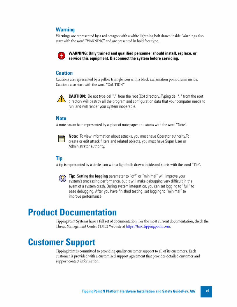
WarningWarnings are represented by a red octagon with a white lightning bolt drawn inside. Warnings also start with the word “WARNING” and are presented in bold face type.
CautionCautions are represented by a yellow triangle icon with a black exclamation point drawn inside. Cautions also start with the word “CAUTION”.
NoteA note has an icon represented by a piece of note paper and starts with the word “Note”.
TipA tip is represented by a circle icon with a light bulb drawn inside and starts with the word “Tip”.
Product DocumentationTippingPoint Systems have a full set of documentation. For the most current documentation, check the Threat Management Center (TMC) Web site at https://tmc.tippingpoint.com.
Customer SupportTippingPoint is committed to providing quality customer support to all of its customers. Each customer is provided with a customized support agreement that provides detailed customer and support contact information.
WARNING: Only trained and qualified personnel should install, replace, or service this equipment. Disconnect the system before servicing.
CAUTION: Do not type del *.* from the root (C:\) directory. Typing del *.* from the root directory will destroy all the program and configuration data that your computer needs to run, and will render your system inoperable.
Note: To view information about attacks, you must have Operator authority.To create or edit attack filters and related objects, you must have Super User or Administrator authority.
Tip: Setting the logging parameter to “off” or “minimal” will improve your system’s processing performance, but it will make debugging very difficult in the event of a system crash. During system integration, you can set logging to “full” to ease debugging. After you have finished testing, set logging to “minimal” to improve performance.
TippingPoint N Platform Hardware Installation and Safety GuideRev. A02 xi

For the most efficient resolution of your problem, take a moment to gather some basic information from your records and from your system before contacting customer support, including your customer number.
Contact InformationFor additional information or assistance, contact TippingPoint Customer Support:
TelephoneNorth America: +1 866 681 8324International: +1 512 681 8324
For a list of international toll-free contact numbers, consult one of the following web pages:
• https://tmc.tippingpoint.com/TMC/Content/support/Support_Contacts
• http://www.tippingpoint.com/support.html
Have the following information available:
Information Location
Your customer number You can find this number on your Customer Support Agreement and on the shipping invoice that came with your TippingPoint system.
Your device serial number You can find this information on the bottom of the server chassis. Also, from the TippingPoint CLI, you can run the show version command.
Your device version number From the TippingPoint CLI, you can run the show version command.
TippingPoint N Platform Hardware Installation and Safety Guide Rev. A02xii

1 System OverviewThe TippingPointTM system is a high-speed, comprehensive security system that includes theIntrusion Prevention System (IPS), TM Local Security Manager (LSM), Digital Vaccine™, theSecurity Management System ApplianceTM, and the Core Controller.
OverviewEnterprise security schemes once consisted of a conglomeration of disparate, static devices from multiple vendors. Today, TippingPoint’s security system provides the advantages of a single, integrated, highly adaptive security system that includes powerful hardware and an intuitive management interface.
This section includes the following topics:
• “TippingPoint Architecture” on page 2
• “Security Management System (SMS)” on page 2
• “Intrusion Prevention System Devices (IPS)” on page 4
• “Core Controller” on page 5
• “High Availability” on page 6
• “Threat Suppression Engine” on page 6
• “Threat Management Center” on page 7
TippingPoint N Platform Hardware Installation and Safety GuideRev. A02 1

Chapter 1—System Overview
TippingPoint ArchitectureThe TippingPoint System uses a flexible architecture that consists of a Java-based SMS Client, SMS Management Server, IPS device(s), and Local Clients including the Local Security Manager (LSM) and Command Line Interface (CLI). The system may also include the Core Controller, a hardware appliance that balances traffic loads for one or more IPSes. The following diagram provides an overview of the architecture:
Security Management System (SMS)The SMS core components include:
• SMS Secure Server —hardware appliance for managing multiple devices
— SMS Home Page — web-based interface with links to current Client software, documentation, and the Threat Management Center
• SMS Management Client — Java-based application for Windows or Linux workstations used to manage your TippingPoint system
— Graphical User Interface (GUI)
— Dashboard
— Command Line Interface (CLI)
The SMS communicates with managed devices that are installed in your network.
Figure 1 - 1: TippingPoint Architecture
TippingPoint N Platform Hardware Installation and Safety Guide Rev. A022
Chapter 1—System Overview
The SMS architecture also includes the following components:
• Threat Management Center (TMC) — Centralized service center that monitors global threats and distributes up-to-date attack filter packages, software updates, and product documentation.
• Digital Vaccine (DV) — Update service that includes up-to-date filter packages for protecting your network
• Managed Devices — TippingPoint IPS or Core Controller devices that are installed in your network
SMS ServerThe SMS Server is an enterprise-class management platform that provides centralized administration, configuration, monitoring and reporting for well over a hundred TippingPoint IPS devices. The SMS provides the following functionality:
• Enterprise-wide device status and behavior monitoring — Stores logs and device status information, manages updates, and monitors filter, device, software, and network status.
• IPS networking and configuration — Stores device information and configures devices according to the settings that are modified, imported, or distributed by clients. These settings affect the flow and detection of traffic according to device, segment, or segment group.
• Filter customization — Stores filter customizations in profiles as maintained by the SMS client. These settings are distributed and imported to devices, which can be reviewed and modified by local clients. If a device is managed by the SMS Server, the local clients cannot modify settings.
• Filter and software distribution — Monitors and maintains the distribution and import of filters, Digital Vaccine packages, and software for the TippingPoint Operating System and SMS Client. The SMS client and Central Management Server can distribute these packages according to segment group settings. The Central Management Server maintains a link to the Threat Management Center (TMC) for downloading and installing package updates.
SMS ClientThe TippingPoint Security Management System (SMS) client provides services and functions to monitor, manage, and configure the entire TippingPoint system. This client is a Java-based application installed and accessed on a computer running the appropriate operating system. Each user receives a specific user level with enhanced security measures to protect access and configuration of the system.
TippingPoint N Platform Hardware Installation and Safety GuideRev. A02 3
Chapter 1—System Overview
You can monitor the entire TippingPoint system through the SMS client on a computer with the following requirements:
• One of the following operating systems:
— Windows 98, 2nd edition
— Windows NT, Service Pack 5 or later
— Windows 2000, Service Pack 3 or later
— Windows XP
— Apple
— Red Hat Linux
• One of the following browsers:
— Microsoft Internet Explorer, version 6.0 or higher
— Firefox
— Safari
The SMS features a policy-based operational model for scalable and uniform enterprise management. It enables behavior and performance analysis with trending reports, correlation and real-time graphs - including reports on all, specific, and top attacks and their sources and destinations as well as all, specific, and top peers and filters for misuse and abuse (peer-to-peer piracy) attacks. You can create, save, and schedule reports using report templates. All reports are run against system and audit logs stored for each device managed by the system. These logs detail triggered filters. You can modify, update, and control distribution of these filters according to segment groups for refined intrusion prevention.
The SMS dashboard provides at-a-glance monitors, with launch capabilities into the targeted management applications that provide global command and control of TippingPoint. It displays the entries for the top 5 filters triggered over the past hour in various categories, a graph of triggered filters over the past 24 hours, the health status of devices, and update versions for software of the system. Through the Dashboard, you gain an overview of the current performance of your system, including notifications of updates and possible issues with devices monitored by the SMS.
Intrusion Prevention System Devices (IPS)Intrusion Prevention System (IPS) devices protect your network with the Threat Suppression Engine (TSE) by scanning, detecting, and responding to network traffic according to the filters, action sets, and global settings maintained on each device by a client.
Each device provides intrusion prevention for your network according to the number of network connections and hardware capabilities. IPS devices also have built-in intrinsic high-availability features, guaranteeing that the network keeps running in the event of system failure.
TippingPoint Intrusion Prevention Systems are optimized to provide high resiliency, high availability security for remote branch offices, small-to-medium and large enterprises and collocation facilities. Each TippingPoint can protect network segments from both external and internal attacks.
TippingPoint N Platform Hardware Installation and Safety Guide Rev. A024

Chapter 1—System Overview
IPS devices provide the following segments and traffic performance:
• TippingPoint 200/200E— Two 10/100 segments, 200 megabits/second
• TippingPoint 210E— Five 10/100/1000 segments, 200 megabits/second.
• TippingPoint 400 — Four 10/100 segments, 400 megabits/second
• TippingPoint 600E— Four 10/10/1000 segments, 600 megabits/second
• TippingPoint 1200/1200E — Four 10/100/1000 segments, 1.2 gigabits/second
• TippingPoint 2400/2400E — Four 10/100/1000 segments, 2.0 gigabits/second
• TippingPoint 5000E — Four 10/100/1000 segments, 5.0 gigabits/second
• TippingPoint 660N— Five 1GbE copper segments, five 1GbE fiber segments, 750 megabits/second
• TippingPoint 1400N — Five 1GbE copper segments, five 1GbE fiber segments, 1.5 gigabits/second
• TippingPoint 2500N — Five 1GbE copper segments, five 1GbE fiber segments, and one 10GbE fiber segment, 3.0 gigabits/second
• TippingPoint 5100N — Five 1GbE copper segments, five 1GbE fiber segments, and one 10GbE fiber segment, 5.0 gigabits/second
Multiple TippingPoint devices can be deployed to extend this unsurpassed protection to hundreds of enterprise zones. You can monitor and manage the devices by using the local client available on each device, or by using the SMS client to monitor and manage well over a hundred devices. E-Series systems provide Advanced DDoS protection. The TippingPoint 660N/1400N/2500N/5100N support IPv6, tunneling (including GRE and multi-layer tunnels), and inspection bypass rules for trusted traffic.
IPS Local ClientsThe TippingPoint System provides various points of interaction, management, and configuration of the intrusion prevention system. The clients include graphical user interfaces (GUI) and command line interfaces (CLI). These clients include the following:
• Local Security Manager (LSM) — Web-based GUI for managing one IPS device. The LSM provides HTTP and HTTPS (secure management) access. This access requires access from a supported web browser (Internet Explorer, Mozilla Firefox, and Netscape). Using the LSM, you have a graphical display for reviewing, searching, and modifying settings. The GUI interface also provides reports to monitor the device traffic, triggered filters, and packet statistics.
• Command Line Interface (CLI) — Command line interface for reviewing and modifying settings on the device. The CLI is accessible through Telnet and SSH (secure access).
• LCD Panel — Several IPS TippingPoint devices provide an LCD panel to view, configure and modify some device settings.
Core ControllerThe TippingPoint Core Controller is a hardware-based device that enables inspection of up to 20 Gbps of traffic by sending the traffic to as many as 24 IPS device segments. The CoreController can control traffic across its three 10GbE network segment pairs and across multiple TippingPoint E-Series IPS devices. IPS devices are connected by 1GbE uplinks, and each packet that is received on a 10GbE
TippingPoint N Platform Hardware Installation and Safety GuideRev. A02 5

Chapter 1—System Overview
CoreController interface passes through a load balancer that then determines the IPS connection to use for transmitting the packet.
The Core Controller provides:
• 10GbE bidirectional traffic inspection and policy enforcement
• High Availability with an optional Smart ZPHA module
• Central management through the SMS
High AvailabilityTippingPoint devices are designed to guarantee that your network traffic always flows at wire speeds in the event of internal device failure. The TippingPoint System provides Network High Availability settings for Intrinsic Network HA (INHA) and Transparent Network HA (TNHA). These options enact manually or automatically, according to settings you enter using the clients (LSM and SMS) or LCD panel for IPS devices. Zero-Power High Availability (ZPHA) is available for the IPS as an external modular device, and for the Core Controller as an optional Smart ZPHA module.
The IPS uses INHA for individual device deployment and TNHA for devices deployed in redundant configurations in which one device takes over for another in the event of system failure. With INHA, a failure puts the device into Layer-2 Fallback mode and permits or blocks traffic on each segment. In TNHA, multiple IPS devices are synchronized so that when one device experiences a system failure, traffic is routed to the other device with no interruption in intrusion prevention services.
SMS high availability provides continuous administration through an active-passive SMS system configuration. A passive SMS is configured, synchronized with the active system, and waits in standby mode and monitors the health of the active system. If the healt or communications check fails, the passive SMS will be activated.
The ZPHA modular device can be attached to an IPS to route traffic in the event of power loss. Smart ZPHA modules perform the same function and are installed directly in the device.
Threat Suppression EngineThe Threat Suppression Engine (TSE) is a line-speed hardware engine that contains all the functions needed for Intrusion Prevention, including IP defragmentation, TCP flow reassembly, statistical analysis, traffic shaping, flow blocking, flow state tracking and application-layer parsing of over 170 network protocols.
The TSE reconstructs and inspects flow payloads by parsing the traffic at the application layer. As each new packet of the traffic flow arrives, the engine re-evaluates the traffic for malicious content. The instant the engine detects malicious traffic, it blocks all current and all subsequent packets pertaining
Note: The Core Controller can be used with the 2400E and 5000E IPS devices, and with all N-Series devices.
TippingPoint N Platform Hardware Installation and Safety Guide Rev. A026

Chapter 1—System Overview
to the traffic flow. The blocking of the traffic and packets ensures that the attack never reaches its destination.
The combination of high-speed network processors and custom chips provide the basis for IPS technology. These highly specialized traffic classification engines enable the IPS to filter with extreme accuracy at gigabit speeds and microsecond latencies. Unlike software-based systems whose performance is affected by the number of filters installed, the highly-scalable capacity of the hardware engine allows thousands of filters to run simultaneously with no impact on performance or accuracy.
Threat Management CenterThe Threat Management Center (TMC) is a centralized service center that monitors global threats and distributes up-to-date attack filter packages, software updates, and product documentation.
The Threat Management Center (TMC) collects threat information and creates Digital Vaccine packages that are made available on the TMC web site. The packages include filters that block malicious traffic and attacks on your network. The filters provide the following protections:
• Application Protection — Defend against known and unknown exploits that target applications and operating systems:
— Attack Protection filters — Detect and block traffic known to be malicious, suspicious, and to have known security implications. These filters include the following: Vulnerabilities and Exploits filters.
— Security Policy filters — Detect and block traffic that may or may not be malicious. This traffic may be different in its format or content from standard business practice, aimed at specific software or operating systems, or contrary to your company’s security policies.
— Reconnaissance filters — Detect and block scans, sweeps, and probes for vulnerabilities and information about your network. These filters include the following: Probes and Sweeps/Scans filters.
— Informational filters — Detect and block classic Intrusion Detection System (IDS) infiltration
• Infrastructure Protection — Protect network bandwidth and network infrastructure elements such as routers and firewalls from attack using a combination of filter types:
— Advanced DDoS filters — Available on the 2400E and 5000E. Detect and block denial of service and flood requests, such as SYN Requests, that can overwhelm a system.
— Network Equipment Protection filters — Protect networked equipment from attacks
— Traffic Normalization filters — Detect and block abnormal or malicious traffic
• Performance Protection — Allow key applications to have prioritized bandwidth access setting that ensure mission critical applications have adequate performance during times of high congestion:
— Misuse and Abuse filters — Protect the resources and usage of file sharing across networks and personal computers. These filters protect peer-to-peer services.
— Traffic Management filters — Protect the network by shielding against IP addresses or permitting only a set of IP addresses
TippingPoint N Platform Hardware Installation and Safety GuideRev. A02 7

Chapter 1—System Overview
TippingPoint N Platform Hardware Installation and Safety Guide Rev. A028

2 TippingPoint Hardware Safety and ComplianceThis document describes TippingPoint product regulatory compliance and provides safetyrequirements and warnings.
OverviewBefore installing your TippingPoint product, you must read through all preparation instructions and safety requirements.
• “Regulatory Compliance and Safety Requirements” on page 10
• “Rack and Clearance Requirements” on page 16
• “Ventilation and Location” on page 16
• “Environmental Requirements” on page 16
• “Reliable Earthing” on page 17
• “ESD Requirements” on page 17
• “Hot Swapping Guidelines” on page 17
• “Unpack the Product” on page 18
TippingPoint N Platform Hardware Installation and Safety GuideRev. A02 9

Chapter 2—TippingPoint Hardware Safety and Compliance
Regulatory Compliance and Safety Requirements
This section describes the product regulatory compliance. It also includes safety information that must be followed to ensure safe operation of the product.
EMC Class A Notices and WarningsThe following EMC Class A Notices and Warnings apply to the product.
Class A Notice for Canada
This Class A digital apparatus meets all requirements of the Canadian Interference-Causing Equipment Regulations.
Cet appareil numérique de la classe A respecte toutes les exigences du Réglement sure le matériel brouilleur du Canada.
Class A Notice for FCC
This device complies with part 15 of the FCC Rules. Operation is subject to the following two conditions: this device may not cause harmful interference, and this device must accept any interference received, including interference that may cause undesired operation.
VCCI Class A Warning for Japan
This is a Class A product based on the standard of the Voluntary Control Council for Interference by Information Technology Equipment (VCCI). If this equipment is used in a domestic environment, radio disturbance may arise. When such trouble occurs, the user may be required to take corrective actions.
Class A Warning for CISPR 22
This is a class A product. In a domestic environment this product may cause radio interference, in which case the user may be required to take adequate measures.
TippingPoint N Platform Hardware Installation and Safety Guide Rev. A0210
Chapter 2—TippingPoint Hardware Safety and Compliance
Directive ComplianceThe following directives and certifications apply to the product.
EMC Environmental Conditions for Products Installed in the European Union
•The installation must be done in a location under the control of the user of the product.•Grounding and bonding shall meet the requirements of ETS 300 253 or CCITT K27.•Where applicable AC power distribution shall be one of the following types: TN-S and
TN-C as defined in IEC 364-3.•Where applicable DC power source shall be SELV and the product must be grounded to
the ground terminal connector labeled with the IEC 60417-5019 symbol.
European Directives
This product complies with the essential requirements and other provisions of Directives 73/23/EEC and 89/336/EEC as amended by Directive 93/68/EEC.
Safety Certifications
•UL 60950-1•CAN/CSA 22.2 No.60950-1•CB to IEC 60950-1 with all country deviations•AS/NZS 60950-1•NOM or NYCE (through partners and distributors)•CE Marking
Electromagnetic Compatibility Certifications
•FCC Part 15 Class A•EN55022 Class A (CISPR22)•EN55024 (CISPR24)•EN 61000-3-2•EN 61000-3-3•VCCI Class A•AS/NZS CISPR22 Class A•MIC Class A•China EMC certifications•CE Marking
TippingPoint N Platform Hardware Installation and Safety GuideRev. A02 11

Chapter 2—TippingPoint Hardware Safety and Compliance
Safety Guidelines and WarningsBefore you start the installation procedures, read this entire section for important information and safety warnings.
If not properly installed and maintained, electrical circuitry equipment can pose dangers to both personnel and equipment. To prevent accidents, adhere to the following guidelines to ensure general safety:
• Remove any dust from the area and keep the area around the product clear and dust-free during and after installation.
• Wear safety glasses if you are working under conditions that might be hazardous to your eyes.
• This product has serviceable modules and hot-swappable power supplies. It has no other serviceable parts inside.
Reduction of Hazardous Substances
Products that bear the marking illustrated below comply with the Hazardous Substances (RoHS) Directive 2002/95/EC .
This product complies with the labeling requirement of the Waste Electrical and Electronic Equipment (WEEE) Directive 2002/96/EC.
TippingPoint N Platform Hardware Installation and Safety Guide Rev. A0212

Chapter 2—TippingPoint Hardware Safety and Compliance
CautionsCautions tell you how to avoid a serious loss that stops short of physical damage such as the loss of data, time, or security. Cautions tell you what you should or should not do to avoid such losses, and the consequences of not heeding the caution.
Do not power up the equipment while you install and connect the system.
If you connect the power improperly and then apply power, the cards and chassis could be damaged.
You are responsible for installing an AC power disconnect for the entire rack unit. This main disconnect must be readily accessible, and it must be labeled as controlling power to the entire unit, not just to the server.
The equipment rack must be anchored to an unmovable support to prevent it from falling over when one or more servers are extended in front of it on slide assemblies. The equipment rack must be installed according to the manufacturer’s instructions. You must also consider the weight of any other device installed in the rack.
Make sure that the chassis cooling fans run continuously while the system is powered.
CAUTION: Make sure all cards are completely connected to the backplane. Improper connections can disrupt system operation.
TippingPoint N Platform Hardware Installation and Safety GuideRev. A02 13
Chapter 2—TippingPoint Hardware Safety and Compliance
WarningsWarnings tell you how to avoid physical injury to people or equipment. For people, injury includes anything from temporary conditions, such as pain, to irreversible conditions such as death. For equipment, injury means anything requiring repair. Warnings tell you what you should or should not do, and the consequences of not heeding the warning.
Installation Warnings
WARNING: Only trained and qualified personnel should install, replace, or service this equipment. Disconnect the power and network cables before servicing.
Read all of the installation instructions before you connect the system to its power source.
When installing the product, always make the ground connection before applying power to the unit. This equipment needs to be grounded to an external ground connection. Use a green and yellow 14 AWG ground wire to connect the host to earth ground during normal use. Disconnect the ground connection only when the unit is completely powered down.
On the product during this procedure, wear grounding wrist straps to avoid ESD damage to cards and modules. Do not directly touch the backplane with your hand or any metal tool, or you could shock yourself.
To prevent personal injury or damage to the chassis, lift the chassis from underneath its lower edge.
This equipment is to be installed and maintained by service personnel only as defined by AS/NZS 60950-1 Service Personnel.
The Installation of this product must comply with local and national electrical codes.
This unit is intended for installation in restricted access areas only.
This product requires short-circuit (overcurrent) protection, to be provided as part of the building installation. Install only in accordance with national and local wiring regulations.
Do not work on the system or connect or disconnect cables during periods of lightning activity.
To prevent the unit from overheating, do not operate it in an area that exceeds the maximum recommended ambient temperature of 104° F (40° C). To prevent airflow restriction, allow at least 3 inches (7.6 cm) of clearance around the ventilation openings.
Enclosed racks may have higher ambient temperatures than open racks. Ensure enclosed racks ambient temperatures do not exceed maximum recommended ambient temperature of 104 °F (40 °C)
The final disposal of this product must be done according to all national laws and regulations.
TippingPoint N Platform Hardware Installation and Safety Guide Rev. A0214

Chapter 2—TippingPoint Hardware Safety and Compliance
Parts Warnings
Do not operate the system unless all cards and top cover is in place.
On the product, do not operate the system unless all cards, faceplates, front covers, and rear covers are in place. Blank faceplates and cover panels serve three important functions: they prevent exposure to hazardous voltages and currents inside the chassis; they contain electromagnetic interference (EMI) that could disrupt other equipment; and they direct the flow of cooling air through the chassis.
To reduce the risk of fire, use only No. 26 AWG or larger telecommunication line cord.
Risk of explosion if battery is replaced by an incorrect type. Dispose of used batteries according to the instructions.
When connecting equipment to IT power distributions, Phase to phase voltage must not exceed 240 V.
The ports on the front of the product are Safety Extra-Low Voltage (SELV) circuits. SELV circuits should only be connected to other SELV circuits.
This product might have more than one power supply source. All power sources must be removed to de-energize the unit.
Never touch uninsulated telephone wires or terminals unless the telephone line has been disconnected at the network interface.
All optical interfaces and sources connected to this product and its modules must only use Class 1 lasers. Using any other Laser Class source can create hazardous conditions to the user.
This product can contain Class 1 lasers. Do not stare into the laser beam or view it directly with optical instruments. Install covers for the laser connectors when they are not in use.
The cards and modules can get hot during operation. When removing a card or module, hold it by the faceplate and bottom edge. Allow the card or module to cool before touching any other part of it or before placing it in an antistatic bag.
The product uses double pole/neutral fusing. Use caution when servicing this product.
TippingPoint N Platform Hardware Installation and Safety GuideRev. A02 15

Chapter 2—TippingPoint Hardware Safety and Compliance
Rack and Clearance RequirementsTipping Point recommends that you mount the product in a standard 19-or 23-inch rack. The vertical hole spacing on the rack rails must meet standard EIA-310-C requirements, which call for a 1.75 inch (44.45 mm) spacing. Ensure that you have a minimum of three inches clearance at the side of the ventilation slots.
Ventilation and LocationVentilation and proper location are essential to the proper operation of the product. Follow these guidelines to ensure that the product receives adequate ventilation.
• When mounting this unit in a partially filled rack, load the rack from the bottom to the top with the heaviest component at the bottom of the rack.
• Ensure that the unit is positioned properly on the rack
• There should be three inches clearance at the ventilation openings.
• When mounting this unit in an enclosed or multi-rack assembly, the operating ambient temperature of the rack may be greater than the room ambient temperature. Ensure that the maximum ambient temperature of 104° F (40 ° C) is not exceeded.
Environmental RequirementsFor the product to run properly, your environment must meet the proper criteria. The following table details the recommendations for temperature, humidity, and altitude settings for the Service Provider (SP) environment.
Table 2 - 1: Environmental Requirements
Environmental Specifications Description
Temperature 0 to 40 ° C (32 to 104 ° F) — Operating-20 to 80° C (-4 to 176 ° F) — Storage
Humidity 5 to 95% (non-condensing)
Altitude No degradation up to 13,000 feet above sea level
TippingPoint N Platform Hardware Installation and Safety Guide Rev. A0216
Chapter 2—TippingPoint Hardware Safety and Compliance
Reliable EarthingEnsure that an external grounding connection is available for the product and follow these guidelines:
• For AC-powered products, use only the AC power cords that have been provided with the product. Using other cords could be hazardous to your safety.
• For DC-powered products, ensure that the product is grounded to the ground termination connector labeled with the IEC 60417-5019 symbol:
Always make the ground connection first when you install the product, ensuring that it is in place before turning on the power or connecting any network cables. When disconnecting the product, remove the ground connection last, only after the power has been completely turned off and all cables have been disconnected.
ESD RequirementsDamage from Electromagnetic Static Discharge (ESD) can occur when electronic components are improperly handled. Its results can be complete or intermittent system failures. Proper ESD protection is required whenever you handle equipment. It is not necessary to open the product chassis to add or remove any components. The following general grounding guidelines apply in the event that a power supply module or ZPHA module must be replaced.
• Always use an ESD wrist strap when adding or removing components from the chassis.
• Avoid touching the circuit boards or connectors on all cards and modules.
• Avoid contact between the printed circuit boards and clothing. The wrist strap only protects components from ESD voltages on the body. ESD voltages on clothing can still cause damage.
• Place a removed component board-side-up on an antistatic surface or in a static-shielding container that is also grounded to the same point as the IPS. If you plan to return the component to the factory, immediately place it in a static-shielding container.
Hot Swapping GuidelinesHot swapping allows you to remove and replace cards without disconnecting power to the system. Some TippingPoint devices allow you to hot swap cards or modules. The TippingPoint has a comprehensive detection system that senses automatically when you add or remove a card or module. It then runs diagnostic and discovery routines and acknowledges the presence or absence of the card.
TippingPoint N Platform Hardware Installation and Safety GuideRev. A02 17

Chapter 2—TippingPoint Hardware Safety and Compliance
If you remove a card or module and replace it with the same type of card or module, the system resumes operation without any operator intervention.
• Do not force the card or module into its slot. This can damage the pins on the backplane if they are not aligned properly with the card or module.
• Ensure that the card or module is straight and not at an angle when you install it in the slot, which can damage the equipment. Use the guide rails to install the card or module correctly.
• Fully depress the ejector tabs to ensure that the card connector mates with the backplane correctly. Firmly seat the card in the slot by locking the card with the black levers.
Unpack the Product Each chassis is securely packaged in a shipping box.
To unpack the product, complete the following steps:
STEP 1 Inspect the packing container. If you see any damage or other signs of mishandling, inform both the local freight provider and TippingPoint before unpacking. Your freight provider can provide you with the procedures necessary to file a claim for damages.
STEP 2 Carefully open the box.
STEP 3 Remove all packing material.
STEP 4 Verify the contents in the shipping package. Compare the packing list to your shipment and to your order. Are all items included? If items are missing, contact your TippingPoint sales or field representative.
STEP 5 Remove the chassis from the box.
STEP 6 Open the accessory kit. It contains the cables, documentation, and management software.
STEP 7 Inspect all the equipment inside for damage. If you think any equipment might be damaged, contact your freight provider for how to lodge a damage claim. Also, contact your TippingPoint sales or field representative for instructions.
CAUTION: ESD can damage the product if you do not take necessary precautions. Installation and maintenance personnel should be properly grounded using ground straps to eliminate the risk of ESD damage to the equipment. All cards and modules are subject to ESD damage whenever they are removed from the chassis.
Use caution when opening the product boxes.
Note: The shipping materials are recyclable. Please save for later use or dispose of them appropriately.
TippingPoint N Platform Hardware Installation and Safety Guide Rev. A0218

3 TippingPoint 660N Device OverviewThis chapter discusses installation of the TippingPoint 660N and its components.
OverviewThis chapter describes the components, chassis, requirements, and installation of the TippingPoint 660N.
Prior to installation, you should also obtain the TippingPoint Command Line Interface Reference v3.x. After installing the components, you will need to complete the TippingPoint Setup Wizard as part of the installation and configuration procedures.
This chapter includes the following sections:
• “Device Overview” on page 20
• “Model Requirements” on page 22
• “Technical Specifications” on page 23
• “Hardware Installation and Configuration” on page 24
TippingPoint N Platform Hardware Installation and Safety GuideRev. A02 19

Chapter 3—TippingPoint 660N Device Overview
Device OverviewThe TippingPoint 660N supports up to 750Mbps of traffic across multiple copper and fiber segments. The chassis is rack-mountable on a 19- or 23-inch rack.
Figure 3 - 1: TippingPoint 660N - Front Panel
Figure 3 - 2: TippingPoint 660N - Back Panel
TippingPoint N Platform Hardware Installation and Safety Guide Rev. A0220
Chapter 3—TippingPoint 660N Device Overview
Chassis FeaturesThis section includes the following topics:
• “Power Switch” on page 21
• “Ports” on page 21
• “LEDs” on page 21
Power Switch The power switch is located on the front panel. The power switch light indicates its current status:
• No light: Device is powered off and no power cables are attached.
• Green: Device is powered on, operating normally.
• Yellow: Device is powered off and power cables are still attached.
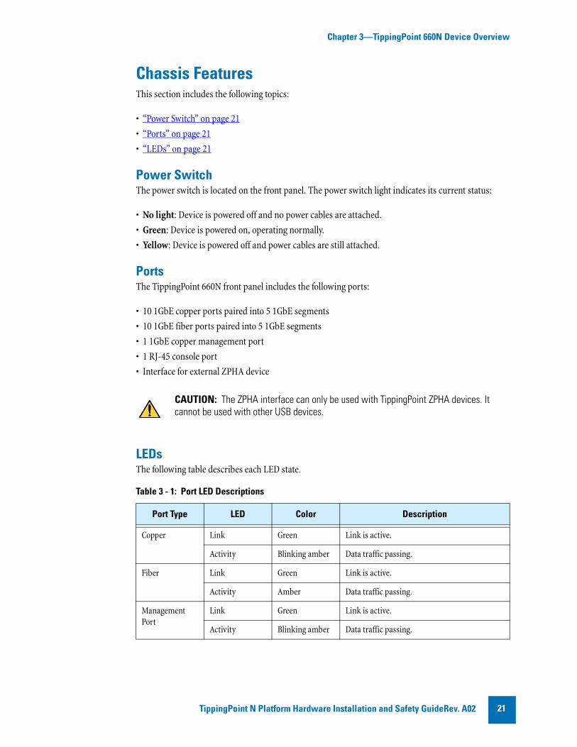
PortsThe TippingPoint 660N front panel includes the following ports:
• 10 1GbE copper ports paired into 5 1GbE segments
• 10 1GbE fiber ports paired into 5 1GbE segments
• 1 1GbE copper management port
• 1 RJ-45 console port
• Interface for external ZPHA device
LEDsThe following table describes each LED state.
CAUTION: The ZPHA interface can only be used with TippingPoint ZPHA devices. It cannot be used with other USB devices.
Table 3 - 1: Port LED Descriptions
Port Type LED Color Description
Copper Link Green Link is active.
Activity Blinking amber Data traffic passing.
Fiber Link Green Link is active.
Activity Amber Data traffic passing.
Management Port
Link Green Link is active.
Activity Blinking amber Data traffic passing.
TippingPoint N Platform Hardware Installation and Safety GuideRev. A02 21

Chapter 3—TippingPoint 660N Device Overview
Model RequirementsThe following sections describe power and cabling requirements for the TippingPoint 660N:
• “Power Requirements” on page 22
• “Cabling Requirements” on page 22
Power Requirements The TippingPoint 660N requires one input of Alternating Current (AC) that must meet the following requirements:
• Voltage: 100-240VAC
• Current: 7-5 amperes
• Frequency: 50/60 Hertz
The device’s maximum power consumption is 520 W.
The TippingPoint 660N power supply modules are hot-swappable. Refer to “Hot Swapping Guidelines” on page 17 for information about hot-swapping modules.
Cabling RequirementsThe TippingPoint 660N ships with the following cables:
• Two AC power cables, one for each hot-swappable power supply
• Null modem cable for the COM management port (DB9 to COM)
You can also receive a Right Angle IEC Receptacle power cord for the device. You can use this cable for connecting power to the device in cases where you may not have enough room for a straight power connection cable. This cable helps in situations when you need to install a device in a tight rack with a door. The 90 degree bend in the female end of the cable prevents the cord from being pinched between the device and the door.
WARNING: This product requires short-circuit (overcurrent) protection, to be provided as part of the building installation. Install only in accordance with national and local wiring regulations.
TippingPoint N Platform Hardware Installation and Safety Guide Rev. A0222

Chapter 3—TippingPoint 660N Device Overview
Technical SpecificationsThe following section describes the hardware, interface, and software specifications for the TippingPoint 660N.
• “Hardware and Interface Specifications” on page 23
• “Software Specifications” on page 23
Hardware and Interface SpecificationsThe following table provides technical specifications for the TippingPoint 660N:
Software SpecificationsTo connect to and configure the TippingPoint 660N, you must have a network-connected PC that supports Internet Explorer 6.x and 7, Firefox 1.5+, Mozilla 1.7+, or Netscape 8.1+.
If you want to use the TippingPoint Security Management System (SMS) to manage the TippingPoint 660N, the TippingPoint SMS device must be installed on your network and you must have the TippingPoint SMS client software V. 3.0+ installed on an appropriate client computer. Refer to the SMS documentation for more information.
Table 3 - 1: TippingPoint 660N Hardware Specifications
Specification Description
Dimensions 2RU - 3.41 in x 16.84 in x 23.46 in (8.67 cm x 42.78 cm x 59.59 cm)
Weight 32.5 lbs (14.74 kg)
Power Requirements 100-240 VAC @ 7-5 amperes, 50/60 HertzMaximum power consumption 520W
Service Provider operating requirements
Temperature 32 to 104° F (0-40° C) — Operating-4 to 158° F (-20 to 70° C) — Storage
Altitude No degradation up to 13,000 feet (3962.4 m)
Humidity 5% to 95% (non-condensing)
External interfaces • 10x1GbE copper ports paired into 5x1GbE segments
• 10x1GbE fiber ports paired into 5x1GbE segments
• 1x1GbE copper management port
• 1x1 RJ-45 console port
• 1 interface for external ZPHA device
• 1 Compact Flash drive
Note: The fiber ports do not include SFP modules.
TippingPoint N Platform Hardware Installation and Safety GuideRev. A02 23

Chapter 3—TippingPoint 660N Device Overview
Hardware Installation and ConfigurationAfter you have completed preparation procedures and unpacked the TippingPoint 660N, you can install and configure the components. Prior to installation, you should also obtain theTippingPoint Command Line Interface Reference v3.x. After installation of the components, you will need to run through the OBE Setup Wizard as part of the installation and configuration procedures.
This section includes the following procedures:
• “TippingPoint 660N Chassis” on page 24
• “Attach Cables” on page 25
• “Check LEDs” on page 26
• “Setup Wizard” on page 26
TippingPoint 660N ChassisTo install the TippingPoint 660N you must do the following:
• “Determine Total Rack Space” on page 24
• “Attach the Device to the Rack” on page 24
• “Connect the Power Supply” on page 25
Determine Total Rack SpaceBefore you install the chassis, you should determine the total rack space that is required to install your system. The required rack space will increase if you plan to install multiple systems. The TippingPoint 660N fits in either a 19-inch or a 23-inch wide rack.
Attach the Device to the RackThe TippingPoint 660N ships with a slide rail kit to mount the device to the rack. Slide rail kits are also available for order from TippingPoint. Refer to the instructions in the slide rail kit for information about installing the slide rails.
If you are bolting the TippingPoint 660N to the rack, follow these guidelines
• If the rack comes with stabilizing devices, install the stabilizers before mounting or servicing the unit in the rack.
• If the rack is partially filled, load the rack from the bottom to the top with the heaviest component at the bottom of the rack.
• If you plan to expand your system to include additional TippingPoint systems in the future, allow space in the rack for additions. During the initial installation, keep in mind the weight distribution and stability of the rack.
WARNING: To prevent bodily injury when mounting or servicing this unit in a rack, you must take special precautions to ensure that the system remains stable.
TippingPoint N Platform Hardware Installation and Safety Guide Rev. A0224

Chapter 3—TippingPoint 660N Device Overview
Connect the Power SupplyAfter you have bolted the TippingPoint 660N to the rack, you need to attach the power supply AC connections. To turn the power on, use the power switch located on the front panel of the device.
The TippingPoint 660N comes with a power cord retention bracket and a cable management assembly. For instructions on installing these accessories, refer to Appendix A‚ “Installing the Power Cord Retention Bracket”.
Attach CablesThe TippingPoint 660N can aggregate and redirect up to 750 Mbps of traffic.The device can distribute this traffic across 1GbE copper or fiber segments. During setup, you will use the console port or the LCD keypad to access the OBE setup wizard.
To attach the Console port connection
1 Connect the RJ-45 null modem cable to the Console port on the unit.
2 Connect the other end of your cable (standard-sized female DB-9 connector) to your VT100-compatible terminal or your computer.
Use the following terminal settings for the Console port:
• Baud rate: 115.2 Kbps
• Character size: 8 bits
• Parity: None
• Stop Bits: One
• Flow Control: None
To attach the Management Processor connection
1 Connect one end of the Category 5 Ethernet cable to the port labeled MGMT (or 10/100 on some units) located on the front panel.
2 Connect the other end of the Ethernet cable to your network. This enables remote management of the system.
To attach network connections
1 Attach the cable for incoming traffic to the A port on the segment.
2 Attach the cable for outgoing traffic to the B port on the segment.
3 Connect the cables to the appropriate ports on your network router.
Note: If you are using a TippingPoint Core Controller to distribute network traffic, attach the cables to the Core Controller 1GbE segment ports. Refer to the Core Controller documentation for more information.
TippingPoint N Platform Hardware Installation and Safety GuideRev. A02 25

Chapter 3—TippingPoint 660N Device Overview
For more information about TippingPoint 660N configuration and network connections, refer to the TippingPoint Local Security Manager User’s Guide v3.x.
Using the External ZPHA ModuleThe TippingPoint 660N can be used with the TippingPoint external ZPHA modular unit. Modular ZPHA devices can be daisy-chained together via netowrk cables and the Type A and Type B USB ports. Refer to the TippingPoint Modular Copper/Fiber ZPHA Installation Guide for more information about this device.
Check LEDs When you connect power to the TippingPoint 660N, the system completes a series of component checks. It then displays LEDs to show the status of each component. See the following sections for information about LEDs for individual components. Refer to “LEDs” on page 21 for more information about the LEDs.
Setup WizardOnce you have powered on, the TippingPoint Setup wizard displays on your COM port terminal.The wizard prompts you to perform basic configuration tasks and periodically input information. You can also use the LCD keypad to perform these tasks. After you run the setup, you can further configure your system using subsequent setup commands through the Command Line Interface (CLI).
See the TippingPoint Command Line Interface Reference v3.x for detailed instructions.
TippingPoint N Platform Hardware Installation and Safety Guide Rev. A0226

4 TippingPoint 1400N Device OverviewThis chapter discusses installation of the TippingPoint 1400N and its components.
OverviewThis chapter describes the components, chassis, requirements, and installation of the TippingPoint 1400N.
Prior to installation, you should also obtain the TippingPoint Command Line Interface Reference v3.x. After installing the components, you will need to complete the TippingPoint Setup Wizard as part of the installation and configuration procedures.
This chapter includes the following sections:
• “Device Overview” on page 28
• “Model Requirements” on page 30
• “Technical Specifications” on page 31
• “Hardware Installation and Configuration” on page 32
TippingPoint N Platform Hardware Installation and Safety GuideRev. A02 27

Chapter 4—TippingPoint 1400N Device Overview
Device OverviewThe TippingPoint 1400N supports up to 1.5 Gbps of traffic across multiple copper and fiber segments.
The TippingPoint 1400N chassis is rack-mountable on a 19- or 23-inch rack.
Figure 4 - 1: TippingPoint 1400N - Front Panel
Figure 4 - 2: TippingPoint 1400N - Back Panel
TippingPoint N Platform Hardware Installation and Safety Guide Rev. A0228

Chapter 4—TippingPoint 1400N Device Overview
Chassis FeaturesThis section includes the following topics:
• “Power Switch” on page 29
• “Ports” on page 29
• “LEDs” on page 29
Power Switch The power switch is located on the front panel. The power switch light indicates its current status:
• No light: Device is powered off and no power cables are attached.
• Green: Device is powered on, operating normally.
• Yellow: Device is powered off and power cables are still attached.
PortsThe TippingPoint 1400N front panel includes the following ports:
• 10 1GbE copper ports paired into 5 1GbE segments
• 10 1GbE fiber ports paired into 5 1GbE segments
• 1 1GbE copper management port
• 1 RJ-45 console port
• Interface for external ZPHA device
LEDsThe following table describes each LED state. .
CAUTION: The ZPHA interface can only be used with TippingPoint ZPHA devices. It cannot be used with other USB devices.
Table 4 - 1: Port LED Descriptions
Port Type LED Color Description
Copper Link Green Link is active.
Activity Blinking amber Data traffic passing.
Fiber Link Green Link is active.
Activity Amber Data traffic passing.
Management Port
Link Green Link is active.
Activity Blinking amber Data traffic passing.
TippingPoint N Platform Hardware Installation and Safety GuideRev. A02 29
Chapter 4—TippingPoint 1400N Device Overview
Model RequirementsThe following sections describe power and cabling requirements for the TippingPoint 1400N:
• “Power Requirements” on page 30
• “Cabling Requirements” on page 30
Power Requirements The TippingPoint 1400N requires one input of Alternating Current (AC) that must meet the following requirements:
• Voltage: 100-240VAC
• Current: 7-5 amperes
• Frequency: 50/60 Hertz
The device’s maximum power consumption is 520 W.
The TippingPoint 1400N power supply modules are hot-swappable. Refer to “Hot Swapping Guidelines” on page 17 for information about hot-swapping modules.
Cabling RequirementsThe TippingPoint 1400N ships with the following cables:
• Two AC power cables, one for each hot-swappable power supply
• Null modem cable for the COM management port (DB9 to COM)
You can also receive a Right Angle IEC Receptacle power cord for the device. You can use this cable for connecting power to the device in cases where you may not have enough room for a straight power connection cable. This cable helps in situations when you need to install a device in a tight rack with a door. The 90 degree bend in the female end of the cable prevents the cord from being pinched between the device and the door.
WARNING: This product requires short-circuit (overcurrent) protection, to be provided as part of the building installation. Install only in accordance with national and local wiring regulations.
TippingPoint N Platform Hardware Installation and Safety Guide Rev. A0230

Chapter 4—TippingPoint 1400N Device Overview
Technical SpecificationsThe following section describes the hardware, interface, and software specifications for the TippingPoint 1400N.
• “Hardware and Interface Specifications” on page 31
• “Software Specifications” on page 31
Hardware and Interface SpecificationsThe following table provides technical specifications for the TippingPoint 1400N:
Software SpecificationsTo connect to and configure the TippingPoint 1400N, you must have a network-connected PC that supports Internet Explorer 6.x and 7, Firefox 1.5+, Mozilla 1.7+, or Netscape 8.1+.
If you want to use the TippingPoint Security Management System (SMS) to manage the TippingPoint 1400N, the TippingPoint SMS device must be installed on your network and you must have the TippingPoint SMS client software V. 3.0+ installed on an appropriate client computer. Refer to the SMS documentation for more information.
Table 4 - 1: TippingPoint 1400N Hardware Specifications
Specification Description
Dimensions 2RU - 3.41 in x 16.84 in x 23.46 in (8.67 cm x 42.78 cm x 59.59 cm)
Weight 32.5 lbs (14.74 kg)
Power Requirements 100-240 VAC @ 7-5 amperes, 50/60 HertzMaximum power consumption 520W
Service Provider operating requirements
Temperature 32 to 104° F (0-40° C) — Operating-4 to 158° F (-20 to 70° C) — Storage
Altitude No degradation up to 13,000 feet (3962.4 m)
Humidity 5% to 95% (non-condensing)
External interfaces • 10x1GbE copper ports paired into 5x1GbE segments
• 10x1GbE fiber ports paired into 5x1GbE segments
• 1x1GbE copper management port
• 1x1 RJ-45 console port
• 1 interface for external ZPHA device
• 1 Compact Flash drive
Note: The fiber ports do not include SFP modules.
TippingPoint N Platform Hardware Installation and Safety GuideRev. A02 31

Chapter 4—TippingPoint 1400N Device Overview
Hardware Installation and ConfigurationAfter you have completed preparation procedures and unpacked the TippingPoint 1400N, you can install and configure the components. Prior to installation, you should also obtain the TippingPoint Command Line Interface Reference v3.x. . After installation of the components, you will need to run through the OBE Setup Wizard as part of the installation and configuration procedures.
This section includes the following procedures:
• “TippingPoint 1400N Chassis” on page 32
• “Attach Cables” on page 33
• “Check LEDs” on page 34
• “Setup Wizard” on page 34
TippingPoint 1400N ChassisTo install the TippingPoint 1400N you must do the following:
• “Determine Total Rack Space” on page 32
• “Attach the Device to the Rack” on page 32
• “Connect the Power Supply” on page 33
Determine Total Rack SpaceBefore you install the chassis, you should determine the total rack space that is required to install your system. The required rack space will increase if you plan to install multiple systems. The TippingPoint 1400N fits in either a 19-inch or a 23-inch wide rack.
Attach the Device to the RackThe TippingPoint 1400N ships with a slide rail kit to mount the device to the rack. Slide rail kits are also available for order from TippingPoint. Refer to the instructions in the slide rail kit for information about installing the slide rails.
If you are bolting the TippingPoint 1400N to the rack, follow these guidelines
• If the rack comes with stabilizing devices, install the stabilizers before mounting or servicing the unit in the rack.
• If the rack is partially filled, load the rack from the bottom to the top with the heaviest component at the bottom of the rack.
• If you plan to expand your system to include additional TippingPoint systems in the future, allow space in the rack for additions. During the initial installation, keep in mind the weight distribution and stability of the rack.
WARNING: To prevent bodily injury when mounting or servicing this unit in a rack, you must take special precautions to ensure that the system remains stable.
TippingPoint N Platform Hardware Installation and Safety Guide Rev. A0232
Chapter 4—TippingPoint 1400N Device Overview
Connect the Power SupplyAfter you have bolted the TippingPoint 1400N to the rack, attach the power supply AC connections. To turn the power on, use the power switch located on the front panel of the device.
The TippingPoint 1400N comes with a power cord retention bracket and a cable management assembly. For instructions on installing these accessories, refer to Appendix A‚ “Installing the Power Cord Retention Bracket”.
Attach CablesThe TippingPoint 1400N can aggregate and redirect up to 1.5 Gbps of traffic.The device can distribute this traffic across 1GbE copper or fiber segments. During setup, you will use the console port or the LCD keypad to access the OBE setup wizard.
To attach the Console port connection
1 Connect the RJ-45 null modem cable to the Console port on the unit.
2 Connect the other end of your cable (standard-sized female DB-9 connector) to your VT100-compatible terminal or your computer.
Use the following terminal settings for the Console port:
• Baud rate: 115.2 Kbps
• Character size: 8 bits
• Parity: None
• Stop Bits: One
• Flow Control: None
To attach the Management Processor connection
1 Connect one end of the Category 5 Ethernet cable to the port labeled MGMT (or 10/100 on some units) located on the front panel.
2 Connect the other end of the Ethernet cable to your network. This enables remote management of the system.
To attach network connections
1 Attach the cable for incoming traffic to the A port on the segment.
2 Attach the cable for outgoing traffic to the B port on the segment.
3 Connect the cables to the appropriate ports on your network router.
Note: If you are using a TippingPoint Core Controller to distribute network traffic, attach the cables to the Core Controller 1GbE segment ports. Refer to the Core Controller documentation for more information.
TippingPoint N Platform Hardware Installation and Safety GuideRev. A02 33

Chapter 4—TippingPoint 1400N Device Overview
For more information about TippingPoint 1400N configuration and network connections, refer to the TippingPoint Local Security Manager User’s Guide v3.x.
Using the External ZPHA ModuleThe TippingPoint 1400N can be used with the TippingPoint external ZPHA modular unit. Modular ZPHA devices can be daisy-chained together via netowrk cables and the Type A and Type B USB ports. Refer to the TippingPoint Modular Copper/Fiber ZPHA Installation Guide for more information about this device.
Check LEDs When you connect power to the TippingPoint 1400N, the system completes a series of component checks. It then displays LEDs to show the status of each component. See the following sections for information about LEDs for individual components. Refer to “LEDs” on page 29 for more information about the LEDs.
Setup WizardOnce you have powered on, the TippingPoint Setup wizard displays on your COM port terminal.The wizard prompts you to perform basic configuration tasks and periodically input information. You can also use the LCD keypad to perform these tasks. After you run the setup, you can further configure your system using subsequent setup commands through the Command Line Interface (CLI).
See the TippingPoint Command Line Interface Reference v3.x for detailed instructions.
TippingPoint N Platform Hardware Installation and Safety Guide Rev. A0234

5 TippingPoint 2500N Device OverviewThis chapter discusses installation of the TippingPoint 2500N and its components.
OverviewThis chapter describes the components, chassis, requirements, and installation of the TippingPoint 2500N.
Prior to installation, you should also obtain the TippingPoint Command Line Interface Reference v3.x. After installing the components, you will need to complete the TippingPoint Setup Wizard as part of the installation and configuration procedures.
This chapter includes the following sections:
• “Device Overview” on page 36
• “Model Requirements” on page 38
• “Technical Specifications” on page 39
• “Hardware Installation and Configuration” on page 40
TippingPoint N Platform Hardware Installation and Safety GuideRev. A02 35
Chapter 5—TippingPoint 2500N Device Overview
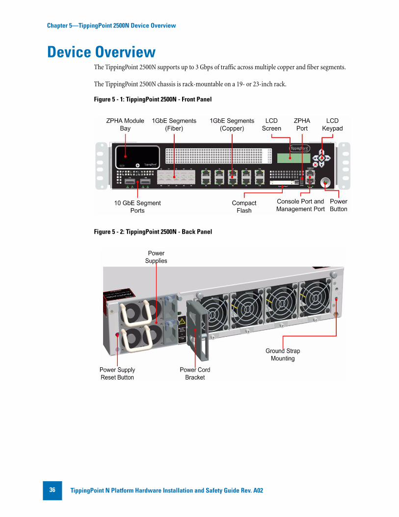
Device OverviewThe TippingPoint 2500N supports up to 3 Gbps of traffic across multiple copper and fiber segments.
The TippingPoint 2500N chassis is rack-mountable on a 19- or 23-inch rack.
Figure 5 - 1: TippingPoint 2500N - Front Panel
Figure 5 - 2: TippingPoint 2500N - Back Panel
TippingPoint N Platform Hardware Installation and Safety Guide Rev. A0236

Chapter 5—TippingPoint 2500N Device Overview
Chassis FeaturesThis section includes the following topics:
• “Power Switch” on page 37
• “Ports” on page 37
• “LEDs” on page 37
Power Switch The power switch is located on the front panel. The power switch light indicates its current status:
• No light: Device is powered off and no power cables are attached.
• Green: Device is powered on, operating normally.
• Yellow: Device is powered off and power cables are still attached.
PortsThe TippingPoint 2500N front panel includes the following ports:
• 10 1GbE copper ports paired into 5 1GbE segments
• 10 1GbE fiber ports paired into 5 1GbE segments
• 1 1GbE copper management port
• 1 RJ-45 console port
• 2 10GbE fiber ports paired into 1 10GbE segment
• Interface for external ZPHA device
LEDsThe following table describes each LED state.
CAUTION: The ZPHA interface can only be used with TippingPoint ZPHA devices. It cannot be used with other USB devices.
Table 5 - 1: Port LED Descriptions
Port Type LED Color Description
Copper Link Green Link is active.
Activity Blinking amber Data traffic passing.
Fiber Link Green Link is active.
Activity Amber Data traffic passing.
Management Port
Link Green Link is active.
Activity Blinking amber Data traffic passing.
TippingPoint N Platform Hardware Installation and Safety GuideRev. A02 37

Chapter 5—TippingPoint 2500N Device Overview
Model RequirementsThe following sections describe power and cabling requirements for the TippingPoint 2500N:
• “Power Requirements” on page 38
• “Cabling Requirements” on page 38
Power Requirements The TippingPoint 2500N requires one input of Alternating Current (AC) that must meet the following requirements:
• Voltage: 100-240VAC
• Current: 7-5 amperes
• Frequency: 50/60 Hertz
The device’s maximum power consumption is 520 W.
The TippingPoint 2500N power supply modules are hot-swappable. Refer to “Hot Swapping Guidelines” on page 17 for information about hot-swapping modules.
Cabling RequirementsThe TippingPoint 2500N ships with the following cables:
• Two AC power cables, one for each hot-swappable power supply
• Null modem cable for the COM management port (DB9 to COM)
You can also receive a Right Angle IEC Receptacle power cord for the device. You can use this cable for connecting power to the device in cases where you may not have enough room for a straight power connection cable. This cable helps in situations when you need to install a device in a tight rack with a door. The 90 degree bend in the female end of the cable prevents the cord from being pinched between the device and the door.
WARNING: This product requires short-circuit (overcurrent) protection, to be provided as part of the building installation. Install only in accordance with national and local wiring regulations.
TippingPoint N Platform Hardware Installation and Safety Guide Rev. A0238

Chapter 5—TippingPoint 2500N Device Overview
Technical SpecificationsThe following section describes the hardware, interface, and software specifications for the TippingPoint 2500N.
• “Hardware and Interface Specifications” on page 39
• “Software Specifications” on page 40
Hardware and Interface SpecificationsThe following table provides technical specifications for the TippingPoint 2500N:
Table 5 - 1: TippingPoint 2500N Hardware Specifications
Specification Description
Dimensions 2RU - 3.41 in x 16.84 in x 23.46 in (8.67 cm x 42.78 cm x 59.59 cm)
Weight 32.5 lbs (14.74 kg)
Power Requirements 100-240 VAC @ 7-5 amperes, 50/60 HertzMaximum power consumption 520W
Service Provider operating requirements
Temperature 32 to 104° F (0-40° C) — Operating-4 to 158° F (-20 to 70° C) — Storage
Altitude No degradation up to 13,000 feet (3962.4 m)
Humidity 5% to 95% (non-condensing)
External interfaces • 10x1GbE copper ports paired into 5x1GbE segments
• 10x1GbE fiber ports paired into 5x1GbE segments
• 2x10GbE fiber ports paired into 1x10GbE segments
• 1x1GbE copper management port
• 1x1 RJ-45 console port
• 1 interface for external ZPHA device
• 1 Compact Flash drive
Note: The fiber ports do not include SFP or XFP modules.
TippingPoint N Platform Hardware Installation and Safety GuideRev. A02 39

Chapter 5—TippingPoint 2500N Device Overview
Software SpecificationsTo connect to and configure the TippingPoint 2500N, you must have a network-connected PC that supports Internet Explorer 6.x and 7, Firefox 1.5+, Mozilla 1.7+, or Netscape 8.1+.
If you want to use the TippingPoint Security Management System (SMS) to manage the TippingPoint 2500N, the TippingPoint SMS device must be installed on your network and you must have the TippingPoint SMS client software V. 3.0+ installed on an appropriate client computer. Refer to the SMS documentation for more information.
Hardware Installation and ConfigurationAfter you have completed preparation procedures and unpacked the TippingPoint 2500N, you can install and configure the components. Prior to installation, you should also obtain the TippingPoint Command Line Interface Reference v3.x. . After installation of the components, you will need to run through the OBE Setup Wizard as part of the installation and configuration procedures.
This section includes the following procedures:
• “TippingPoint 2500N Chassis” on page 40
• “Attach Cables” on page 41
• “Check LEDs” on page 42
• “Setup Wizard” on page 42
TippingPoint 2500N ChassisTo install the TippingPoint 2500N you must do the following:
• “Determine Total Rack Space” on page 40
• “Attach the Device to the Rack” on page 40
• “Connect the Power Supply” on page 41
Determine Total Rack SpaceBefore you install the chassis, you should determine the total rack space that is required to install your system. The required rack space will increase if you plan to install multiple systems. The TippingPoint 2500N fits in either a 19-inch or a 23-inch wide rack.
Attach the Device to the RackThe TippingPoint 2500N ships with a slide rail kit to mount the device to the rack. Slide rail kits are also available for order from TippingPoint. Refer to the instructions in the slide rail kit for information about installing the slide rails.
TippingPoint N Platform Hardware Installation and Safety Guide Rev. A0240

Chapter 5—TippingPoint 2500N Device Overview
If you are bolting the TippingPoint 2500N to the rack, follow these guidelines
• If the rack comes with stabilizing devices, install the stabilizers before mounting or servicing the unit in the rack.
• If the rack is partially filled, load the rack from the bottom to the top with the heaviest component at the bottom of the rack.
• If you plan to expand your system to include additional TippingPoint systems in the future, allow space in the rack for additions. During the initial installation, keep in mind the weight distribution and stability of the rack.
Connect the Power SupplyAfter you have bolted the TippingPoint 2500N to the rack, attach the power supply AC connections. To turn the power on, use the power switch located on the front panel of the device.
The TippingPoint 2500N comes with a power cord retention bracket and a cable management assembly. For instructions on installing these accessories, refer to Appendix A‚ “Installing the Power Cord Retention Bracket”.
Attach CablesThe TippingPoint 2500N can aggregate and redirect up to 3 Gbps of traffic.The device can distribute this traffic across 1GbE copper or fiber segments. During setup, you will use the management processor connection or the console port to access the OBE setup wizard.
To attach the Console port connection
1 Connect the RJ-45 null modem cable to the Console port on the unit.
2 Connect the other end of your cable (standard-sized female DB-9 connector) to your VT100-compatible terminal or your computer.
Use the following terminal settings for the Console port:
• Baud rate: 115.2 Kbps
• Character size: 8 bits
• Parity: None
• Stop Bits: One
• Flow Control: None
WARNING: To prevent bodily injury when mounting or servicing this unit in a rack, you must take special precautions to ensure that the system remains stable.
TippingPoint N Platform Hardware Installation and Safety GuideRev. A02 41

Chapter 5—TippingPoint 2500N Device Overview
To attach the Management Processor connection
1 Connect one end of the Category 5 Ethernet cable to the port labeled MGMT (or 10/100 on some units) located on the front panel.
2 Connect the other end of the Ethernet cable to your network. This enables remote management of the system.
To attach network connections
1 Attach the cable for incoming traffic to the A port on the segment.
2 Attach the cable for outgoing traffic to the B port on the segment.
3 Connect the cables to the appropriate ports on your network router.
For more information about TippingPoint 2500N configuration and network connections, refer to the TippingPoint Local Security Manager User’s Guide v3.x.
Using ZPHAThe TippingPoint 2500N can be used with the TippingPoint external ZPHA modular unit. Modular ZPHA devices can be daisy-chained together via netowrk cables and the Type A and Type B USB ports. Refer to the TippingPoint Modular Copper/Fiber ZPHA Installation Guide for more information about this device.
The TippingPoint 2500N can also use the Smart ZPHA module with the 10GbE segment. Refer to the TippignPoint SmartZPHA Module Installation and Safety Guide for more information about this module.
Check LEDs When you connect power to the TippingPoint 2500N, the system completes a series of component checks. It then displays LEDs to show the status of each component. See the following sections for information about LEDs for individual components. Refer to “LEDs” on page 37 for more information about the LEDs.
Setup WizardOnce you have powered on, the TippingPoint Setup wizard displays on your COM port terminal.The wizard prompts you to perform basic configuration tasks and periodically input information. You can also use the LCD keypad to perform these tasks. After you run the setup, you can further configure your system using subsequent setup commands through the Command Line Interface (CLI).
See the TippingPoint Command Line Interface Reference v3.x for detailed instructions.
Note: If you are using a TippingPoint Core Controller to distribute network traffic, attach the cables to the Core Controller 1GbE segment ports. Refer to the Core Controller documentation for more information.
TippingPoint N Platform Hardware Installation and Safety Guide Rev. A0242

Chapter 5—TippingPoint 2500N Device Overview
TippingPoint N Platform Hardware Installation and Safety GuideRev. A02 43

Chapter 5—TippingPoint 2500N Device Overview
TippingPoint N Platform Hardware Installation and Safety Guide Rev. A0244

6 TippingPoint 5100N Device OverviewThis chapter discusses installation of the TippingPoint 5100N and its components.
OverviewThis chapter describes the components, chassis, requirements, and installation of the TippingPoint 5100N.
Prior to installation, you should also obtain the TippingPoint Command Line Interface Reference v3.x. After installing the components, you will need to complete the TippingPoint Setup Wizard as part of the installation and configuration procedures.
This chapter includes the following sections:
• “Chassis Overview” on page 46
• “Model Requirements” on page 48
• “Technical Specifications” on page 49
• “Hardware Installation and Configuration” on page 50
TippingPoint N Platform Hardware Installation and Safety GuideRev. A02 45

Chapter 6—TippingPoint 5100N Device Overview
Chassis OverviewThe TippingPoint 5100N supports up to 5 Gbps of traffic across multiple copper and fiber segments.
The TippingPoint 5100N chassis is rack-mountable on a 19- or 23-inch rack.
Figure 6 - 1: TippingPoint 5100N - Front Panel
Figure 6 - 2: TippingPoint 5100N - Back Panel
TippingPoint N Platform Hardware Installation and Safety Guide Rev. A0246
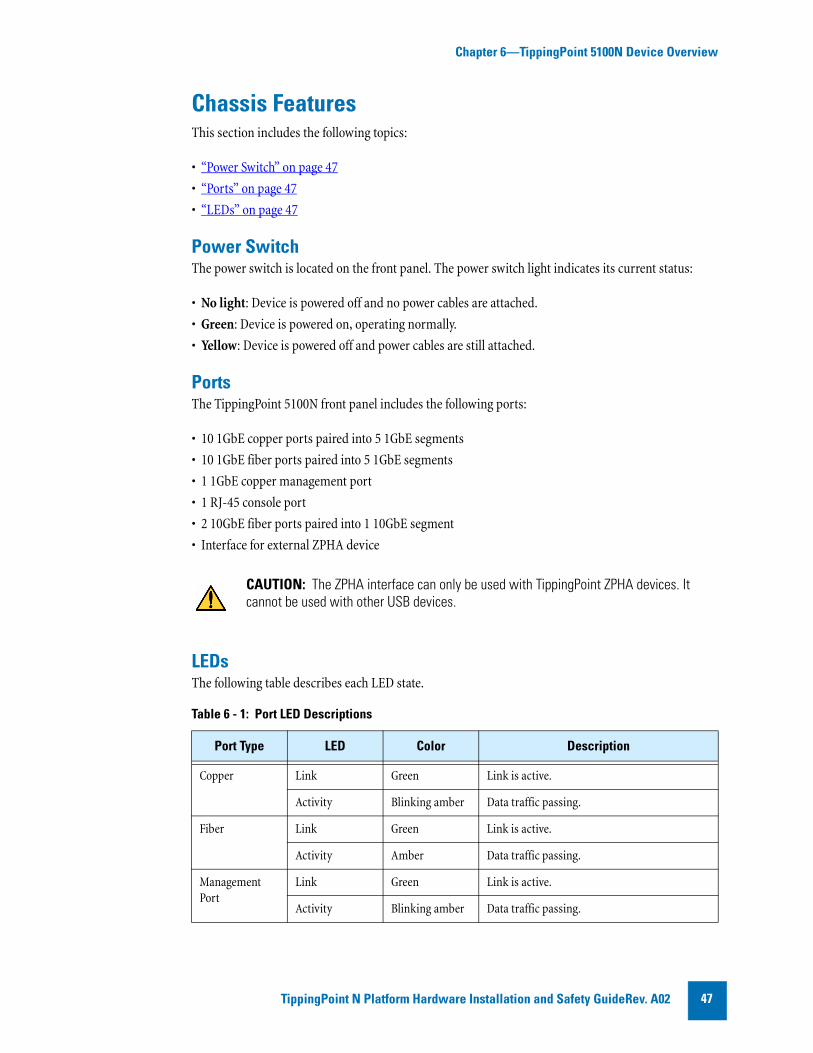
Chapter 6—TippingPoint 5100N Device Overview
Chassis FeaturesThis section includes the following topics:
• “Power Switch” on page 47
• “Ports” on page 47
• “LEDs” on page 47
Power Switch The power switch is located on the front panel. The power switch light indicates its current status:
• No light: Device is powered off and no power cables are attached.
• Green: Device is powered on, operating normally.
• Yellow: Device is powered off and power cables are still attached.
PortsThe TippingPoint 5100N front panel includes the following ports:
• 10 1GbE copper ports paired into 5 1GbE segments
• 10 1GbE fiber ports paired into 5 1GbE segments
• 1 1GbE copper management port
• 1 RJ-45 console port
• 2 10GbE fiber ports paired into 1 10GbE segment
• Interface for external ZPHA device
LEDsThe following table describes each LED state.
CAUTION: The ZPHA interface can only be used with TippingPoint ZPHA devices. It cannot be used with other USB devices.
Table 6 - 1: Port LED Descriptions
Port Type LED Color Description
Copper Link Green Link is active.
Activity Blinking amber Data traffic passing.
Fiber Link Green Link is active.
Activity Amber Data traffic passing.
Management Port
Link Green Link is active.
Activity Blinking amber Data traffic passing.
TippingPoint N Platform Hardware Installation and Safety GuideRev. A02 47

Chapter 6—TippingPoint 5100N Device Overview
Model RequirementsThe following sections describe power and cabling requirements for the TippingPoint 5100N:
• “Power Requirements” on page 48
• “Cabling Requirements” on page 48
Power Requirements The TippingPoint 5100N requires one input of Alternating Current (AC) that must meet the following requirements:
• Voltage: 100-240VAC
• Current: 7-5 amperes
• Frequency: 50/60 Hertz
The device’s maximum power consumption is 520 W.
The TippingPoint 5100N power supply modules are hot-swappable. Refer to “Hot Swapping Guidelines” on page 17 for information about hot-swapping modules.
Cabling RequirementsThe TippingPoint 5100N ships with the following cables:
• Two AC power cables, one for each hot-swappable power supply
• Null modem cable for the COM management port (DB9 to COM)
You can also receive a Right Angle IEC Receptacle power cord for the device. You can use this cable for connecting power to the device in cases where you may not have enough room for a straight power connection cable. This cable helps in situations when you need to install a device in a tight rack with a door. The 90 degree bend in the female end of the cable prevents the cord from being pinched between the device and the door.
WARNING: This product requires short-circuit (overcurrent) protection, to be provided as part of the building installation. Install only in accordance with national and local wiring regulations.
TippingPoint N Platform Hardware Installation and Safety Guide Rev. A0248
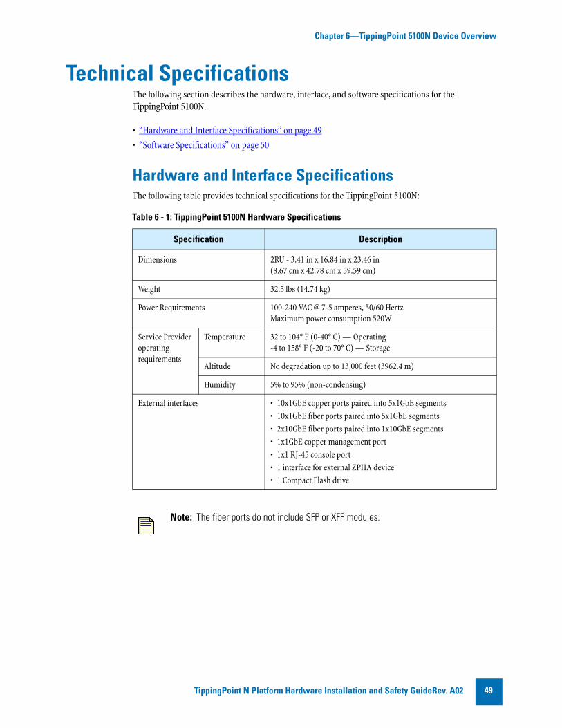
Chapter 6—TippingPoint 5100N Device Overview
Technical SpecificationsThe following section describes the hardware, interface, and software specifications for the TippingPoint 5100N.
• “Hardware and Interface Specifications” on page 49
• “Software Specifications” on page 50
Hardware and Interface SpecificationsThe following table provides technical specifications for the TippingPoint 5100N:
Table 6 - 1: TippingPoint 5100N Hardware Specifications
Specification Description
Dimensions 2RU - 3.41 in x 16.84 in x 23.46 in (8.67 cm x 42.78 cm x 59.59 cm)
Weight 32.5 lbs (14.74 kg)
Power Requirements 100-240 VAC @ 7-5 amperes, 50/60 HertzMaximum power consumption 520W
Service Provider operating requirements
Temperature 32 to 104° F (0-40° C) — Operating-4 to 158° F (-20 to 70° C) — Storage
Altitude No degradation up to 13,000 feet (3962.4 m)
Humidity 5% to 95% (non-condensing)
External interfaces • 10x1GbE copper ports paired into 5x1GbE segments
• 10x1GbE fiber ports paired into 5x1GbE segments
• 2x10GbE fiber ports paired into 1x10GbE segments
• 1x1GbE copper management port
• 1x1 RJ-45 console port
• 1 interface for external ZPHA device
• 1 Compact Flash drive
Note: The fiber ports do not include SFP or XFP modules.
TippingPoint N Platform Hardware Installation and Safety GuideRev. A02 49
Chapter 6—TippingPoint 5100N Device Overview
Software SpecificationsTo connect to and configure the TippingPoint 5100N, you must have a network-connected PC that supports Internet Explorer 6.x and 7, Firefox 1.5+, Mozilla 1.7+, or Netscape 8.1+.
If you want to use the TippingPoint Security Management System (SMS) to manage the TippingPoint 5100N, the TippingPoint SMS device must be installed on your network and you must have the TippingPoint SMS client software V. 3.0+ installed on an appropriate client computer. Refer to the SMS documentation for more information.
Hardware Installation and ConfigurationAfter you have completed preparation procedures and unpacked the TippingPoint 5100N, you can install and configure the components. Prior to installation, you should also obtain the TippingPoint Command Line Interface Reference v3.x. After installation of the components, you will need to run through the OBE Setup Wizard as part of the installation and configuration procedures.
This section includes the following procedures:
• “TippingPoint 5100N Chassis” on page 50
• “Attach Cables” on page 51
• “Check LEDs” on page 52
• “Setup Wizard” on page 52
TippingPoint 5100N ChassisTo install the TippingPoint 5100N you must do the following:
• “Determine Total Rack Space” on page 50
• “Attach the Device to the Rack” on page 50
• “Connect the Power Supply” on page 51
Determine Total Rack SpaceBefore you install the chassis, you should determine the total rack space that is required to install your system. The required rack space will increase if you plan to install multiple systems. The TippingPoint 5100N fits in either a 19-inch or a 23-inch wide rack.
Attach the Device to the RackThe TippingPoint 5100N ships with a slide rail kit to mount the device to the rack. Slide rail kits are also available for order from TippingPoint. Refer to the instructions in the slide rail kit for information about installing the slide rails.
TippingPoint N Platform Hardware Installation and Safety Guide Rev. A0250
Chapter 6—TippingPoint 5100N Device Overview
If you are bolting the TippingPoint 5100N to the rack, follow these guidelines
• If the rack comes with stabilizing devices, install the stabilizers before mounting or servicing the unit in the rack.
• If the rack is partially filled, load the rack from the bottom to the top with the heaviest component at the bottom of the rack.
• If you plan to expand your system to include additional TippingPoint systems in the future, allow space in the rack for additions. During the initial installation, keep in mind the weight distribution and stability of the rack.
Connect the Power SupplyAfter you have bolted the TippingPoint 5100N to the rack, attach the power supply AC connections. To turn the power on, use the power switch located on the front panel of the device.
The TippingPoint 5100N comes with a power cord retention bracket and a cable management assembly. For instructions on installing these accessories, refer to Appendix A‚ “Installing the Power Cord Retention Bracket”.
Attach CablesThe TippingPoint 5100N can aggregate and redirect up to 5 Gbps of traffic.The device can distribute this traffic across 1GbE copper or fiber segments. During setup, you will use the management processor connection or the console port to access the OBE setup wizard.
To attach the Console port connection
1 Connect the RJ-45 null modem cable to the Console port on the unit.
2 Connect the other end of your cable (standard-sized female DB-9 connector) to your VT100-compatible terminal or your computer.
Use the following terminal settings for the Console port:
• Baud rate: 115.2 Kbps
• Character size: 8 bits
• Parity: None
• Stop Bits: One
• Flow Control: None
WARNING: To prevent bodily injury when mounting or servicing this unit in a rack, you must take special precautions to ensure that the system remains stable.
TippingPoint N Platform Hardware Installation and Safety GuideRev. A02 51

Chapter 6—TippingPoint 5100N Device Overview
To attach the Management Processor connection
1 Connect one end of the Category 5 Ethernet cable to the port labeled MGMT (or 10/100 on some units) located on the front panel.
2 Connect the other end of the Ethernet cable to your network. This enables remote management of the system.
To attach network connections
1 Attach the cable for incoming traffic to the A port on the segment.
2 Attach the cable for outgoing traffic to the B port on the segment.
3 Connect the cables to the appropriate ports on your network router.
For more information about TippingPoint 5100N configuration and network connections, refer to the TippingPoint Local Security Manager User’s Guide v3.x.
Using ZPHAThe TippingPoint 5100N can be used with the TippingPoint external ZPHA modular unit. Modular ZPHA devices can be daisy-chained together via netowrk cables and the Type A and Type B USB ports. Refer to the TippingPoint Modular Copper/Fiber ZPHA Installation Guide for more information about this device.
The TippingPoint 5100N can also use the Smart ZPHA module with the 10GbE segment. Refer to the TippignPoint SmartZPHA Module Installation and Safety Guide for more information about this module.
Check LEDs When you connect power to the TippingPoint 5100N, the system completes a series of component checks. It then displays LEDs to show the status of each component. See the following sections for information about LEDs for individual components. Refer to “LEDs” on page 47 for more information about the LEDs.
Setup WizardOnce you have powered on, the TippingPoint Setup wizard displays on your COM port terminal.The wizard prompts you to perform basic configuration tasks and periodically input information. You can also use the LCD keypad to perform these tasks. After you run the setup, you can further configure your system using subsequent setup commands through the Command Line Interface (CLI).
See the TippingPoint Command Line Interface Reference v3.x. for detailed instructions.
Note: If you are using a TippingPoint Core Controller to distribute network traffic, attach the cables to the Core Controller 1GbE segment ports. Refer to the Core Controller documentation for more information.
TippingPoint N Platform Hardware Installation and Safety Guide Rev. A0252

Chapter 6—TippingPoint 5100N Device Overview
TippingPoint N Platform Hardware Installation and Safety GuideRev. A02 53

Chapter 6—TippingPoint 5100N Device Overview
TippingPoint N Platform Hardware Installation and Safety Guide Rev. A0254

A Installing the Power Cord Retention BracketThis appendix provides installation instructions for the power cord retention bracket . The following subjects are discussed.
• “Power Cord Retention Bracket” on page 56
• “Installing and Using the Bracket” on page 56
• “Removing the Bracket” on page 57
TippingPoint N Platform Hardware Installation and Safety GuideRev. A02 55

Appendix A—Installing the Power Cord Retention Bracket
Power Cord Retention BracketThe power cord retention bracket (part number SBASY-0000000437) helps reduce strain on the power cord and power supply outlets.
Installing and Using the BracketThe following figure shows an N-Series with the power cord retention bracket installed:
Follow the procedures in this section to install and use the power cord retention bracket and the cable management bracket.
Figure A - 3: Power Cord Retention Bracket
Figure A - 4: Installed Brackets
TippingPoint N Platform Hardware Installation and Safety Guide Rev. A0256

Appendix A—Installing the Power Cord Retention Bracket
Installing the BracketUse the following procedure to install the power cord retention bracket.
1 Orient the bracket against the back surface of the chassis.
2 Slide the bracket over the two shoulder rivets on the back of the chassis. The spring-loaded plunger in the center of the bracket slides into place.
Using the Power Cord Retention BracketFollow this procedure to attach the power cord to the retention bracket.
1 Fold the power cable and slide it into the slot.
2 Push the folded cable into the slot until the cable loop goes past the sheet metal tabs.
3 Secure the folded cable loop under the sheet metal tabs and attach the power cable to the power supply.
Removing the BracketIf you need to remove one of the brackets, pull the spring-loaded plunger in the middle of the bracket and slide the bracket up and off the shoulder rivets.
TippingPoint N Platform Hardware Installation and Safety GuideRev. A02 57

Appendix A—Installing the Power Cord Retention Bracket
TippingPoint N Platform Hardware Installation and Safety Guide Rev. A0258

B Power Supply ModulesThis appendix provides installation instructions for the power supply modules. The following subjects are discussed.
• “AC Power Supply” on page 60
• “DC Power Supply” on page 61
WARNING: This product may have more than one power supply souce. All power sources must be removed to de-energize the unit.
Note: This product has serviceable modules and hot-swappable power supplies. It has no other serviceable parts inside.
TippingPoint N Platform Hardware Installation and Safety GuideRev. A02 59
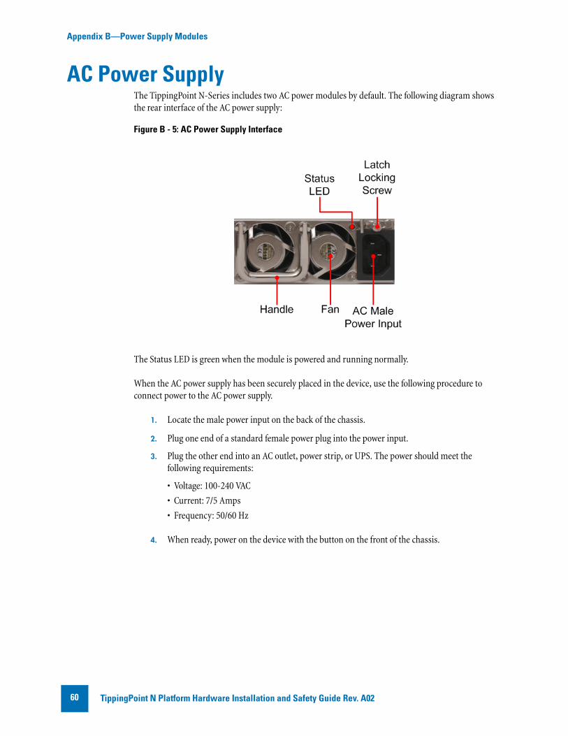
Appendix B—Power Supply Modules
AC Power SupplyThe TippingPoint N-Series includes two AC power modules by default. The following diagram shows the rear interface of the AC power supply:
The Status LED is green when the module is powered and running normally.
When the AC power supply has been securely placed in the device, use the following procedure to connect power to the AC power supply.
1. Locate the male power input on the back of the chassis.
2. Plug one end of a standard female power plug into the power input.
3. Plug the other end into an AC outlet, power strip, or UPS. The power should meet the following requirements:
• Voltage: 100-240 VAC
• Current: 7/5 Amps
• Frequency: 50/60 Hz
4. When ready, power on the device with the button on the front of the chassis.
Figure B - 5: AC Power Supply Interface
TippingPoint N Platform Hardware Installation and Safety Guide Rev. A0260
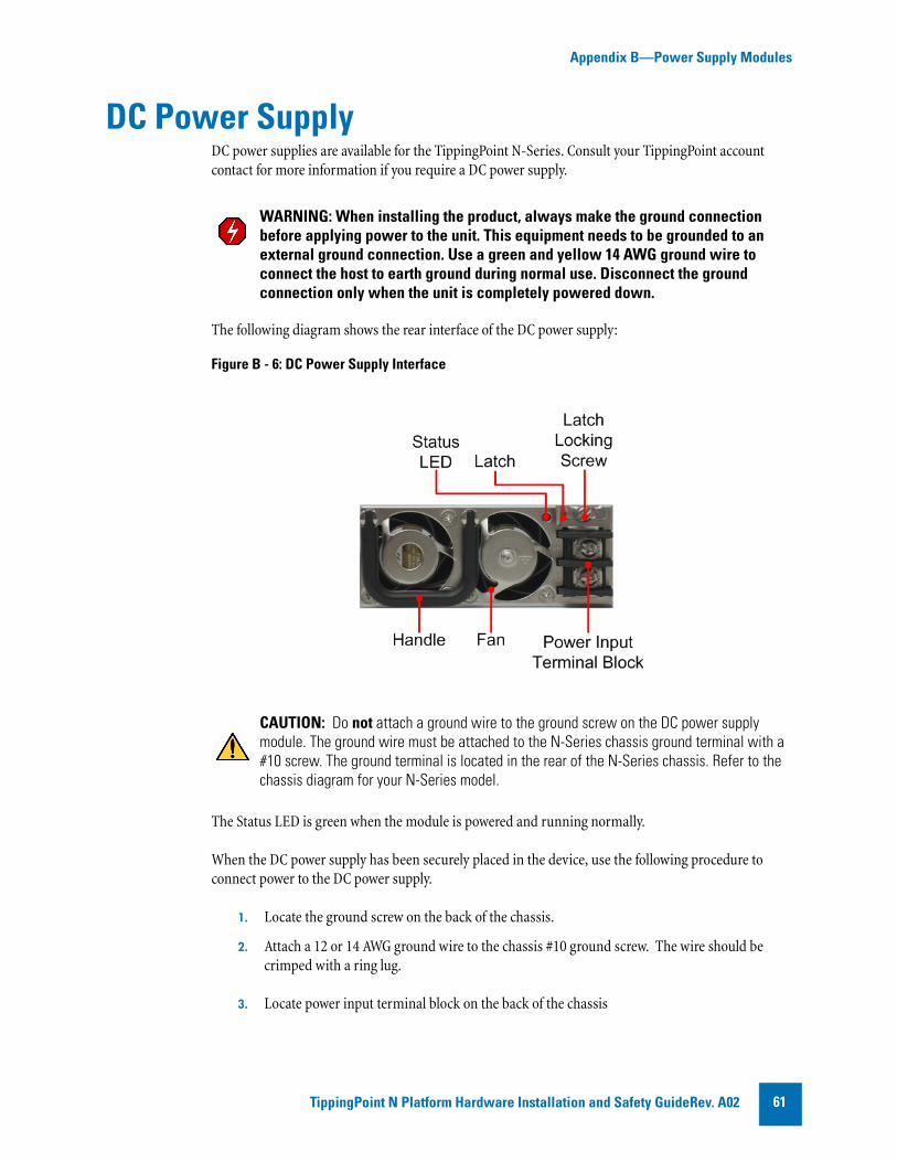
Appendix B—Power Supply Modules
DC Power SupplyDC power supplies are available for the TippingPoint N-Series. Consult your TippingPoint account contact for more information if you require a DC power supply.
The following diagram shows the rear interface of the DC power supply:
The Status LED is green when the module is powered and running normally.
When the DC power supply has been securely placed in the device, use the following procedure to connect power to the DC power supply.
1. Locate the ground screw on the back of the chassis.
2. Attach a 12 or 14 AWG ground wire to the chassis #10 ground screw. The wire should be crimped with a ring lug.
3. Locate power input terminal block on the back of the chassis
WARNING: When installing the product, always make the ground connection before applying power to the unit. This equipment needs to be grounded to an external ground connection. Use a green and yellow 14 AWG ground wire to connect the host to earth ground during normal use. Disconnect the ground connection only when the unit is completely powered down.
Figure B - 6: DC Power Supply Interface
CAUTION: Do not attach a ground wire to the ground screw on the DC power supply module. The ground wire must be attached to the N-Series chassis ground terminal with a #10 screw. The ground terminal is located in the rear of the N-Series chassis. Refer to the chassis diagram for your N-Series model.
TippingPoint N Platform Hardware Installation and Safety GuideRev. A02 61

Appendix B—Power Supply Modules
4. Attach the 12 or 14 AWG DC power wires to the power input terminal block labeled -48V and RTN. The power wires should be crimped with lug spades to ensure a secure connection.
5. Connect the other side of the power cable to the SELV power source. The power source should meet the following requirements:
• Voltage: -36 to -60 Vdc +/- 20% SELV
• Current: 8/4 Amps
6. When ready, power on the device with the button on the front of the chassis.
TippingPoint N Platform Hardware Installation and Safety Guide Rev. A0262

C Using the LCD PanelThis appendix discusses the LCD panel. The LCD panel can be used to perform initial device configuration, as well as other maintenance tasks.
The following subjects are discussed:
• “Features of the LCD Keypad” on page 63
• “Configuring the TippingPoint IPS With the LCD Panel” on page 64
• “Other LCD Panel Tasks” on page 65
Features of the LCD KeypadThe LCD keypad uses the following buttons to navigate the LCD interface and edit input.
• Accept: Accepts the input on the current screen and moves to the next screen.
• Cancel: Navigates back to the previous screen.
• Arrow Keys: Used to enter numerals or Yes/No input. When you enter numerals, the up and down keys cycle through the numbers 0-9, and the left and right keys move the cursor.
Figure C - 7: TippingPoint IPS LCD Screen and Keypad
TippingPoint N Platform Hardware Installation and Safety GuideRev. A02 63

Appendix C—Using the LCD Panel
Configuring the TippingPoint IPS With the LCD Panel
The following steps describe the use of the LCD panel to perform the initial configuration tasks on the TippingPoint IPS device. Throughout this procedure, use the Accept button to move to the next screen. At any time, you can move to the previous step in the wizard by pressing the Cancel button.
7. Turn on the device power.
The system will display a welcome screen and a message indicating that the device is initializing.
8. When prompted to perform the initial setup with the LCD panel, press the Accept button to indicate that you want to proceed with the OBE. You will be prompted a second time to con-firm.
9. The system will generate a random initial super-user name and password. Record this infor-mation.
10. The system will prompt you to enter a host name. By default, the host name is set to NCP00. You can edit the numerals, but not the letters.
11. Enter the management IP address and netmask IP address with the arrow keys.
12. Indicate whether a gateway IP address is required. If so, use the arrow keys to configure the IP address.
13. Select a time zone by using the arrow keys to scroll through the list of available time zones.
14. Indicate if Daylight Saving Time is required.
15. Press the Accept button to complete the configuration process.
After the configuration process is complete, the TippingPoint IPS will complete the boot-up process. You can now log on to the device through the CLI or LSM using the super-user name and password generated in Step 3.
After you have completed the initial setup wizard, you can use the Local Security Manager GUI to perform monitoring and configuration tasks or use the setup command in the CLI to perform
Note: Currently, you cannot enter IPv6 addresses with the LCD panel. If you require IPv6 connectivity, use the CLI OBE.
CAUTION: Without the system-generated super-user name and password, you will not be able to log into the TippingPoint IPS device.
Note: When the LCD OBE wizard is in process, the console connected to the device displays a message stating that “Initial Setup is currently in process via the LCD Panel”.
TippingPoint N Platform Hardware Installation and Safety Guide Rev. A0264

Appendix C—Using the LCD Panel
additional configuration tasks. Refer to the TippingPoint Command Line Interface Reference for more information.
Other LCD Panel TasksIn addition to configuration tasks, you can use the LCD panel to view device status or perform maintenance tasks. To access these options, press the Up or Down buttons to scroll through the LCD menu.
The following options are available on the LCD menu:
• Thermal Query: Displays the device temperature.
• Serial # Query: Displays the device serial number.
• Reload OS: Follow the prompts to re-install the operating system on the device.
• Memory Usage: Displays the current memory usage.
• Layer-2 Fallback: Follow the prompts to place the device in Layer-2 Fallback.
• Halt OS: Shuts down the IPS.
• HA State Query: Displays the current High Availability state and settings.
• Contrast Set: Set the display contrast for the LCD panel.
• Backlight Set: Set the backlight level for the LCD panel.
• Eject CF: See “Managing the Compact Flash in the LCD Panel” on page 68.
TippingPoint N Platform Hardware Installation and Safety GuideRev. A02 65

Appendix C—Using the LCD Panel
TippingPoint N Platform Hardware Installation and Safety Guide Rev. A0266

D Using the Compact Flash CardThis chapter discusses the compact flash card. The following topics are discussed:
• “About the Compact Flash Card” on page 67
• “Compact Flash Commands” on page 68
• “Managing the Compact Flash in the LCD Panel” on page 68
About the Compact Flash CardThe compact flash card is used to store system logs, snapshots, and other system data. The user can remove and insert the compact flash card while the device is running; however, the user must be sure to issue the appropriate mounting and preparation commands in the command line interface (CLI).
The device will continue to perform correctly if the compact flash card is not available. However, if you attempt to take a system snapshot, the operation will fail and an error will be recorded in the system log.
The device comes with a pre-formatted compact flash card. You may use other blank compact flash cards up to 16 GB in size; you must format the card with the compact-flash format command.
TippingPoint N Platform Hardware Installation and Safety GuideRev. A02 67

Appendix D—Using the Compact Flash Card
Compact Flash CommandsThe following table lists the commands used to manage the compact flash card in the CLI. Refer to the TippingPoint Command Line Interface Reference for detailed documentation of these commands.
Managing the Compact Flash in the LCD PanelThe LCD panel offers a menu option that performs the same function as the compact-flash unmount command in the CLI.
Unmounting and Ejecting the Compact Flash Card
1. On the LCD panel, use the Up or Down arrow buttons to navigate to the Eject CF? menu option.
2. Press the check button to select the option.
3. When prompted to verify the action, press the check button again.
4. When the display indicates that the unmount operation was successful, you can remove the compact flash card.
Ejecting a compact flash card may fail after a 30-second timeout if the card is in use. The most common cause for failure is if a snapshot is being written to the card when the Eject command is issued.
Table D - 2: Compact Flash Commands
Command Description
compact-flash format Formats a new compact flash card that has not already been formatted according to TippingPoint guidelines.
compact-flash mount Manually mounts the inserted compact flash card.
compact-flash unmount Unmounts the compact flash card so that the user can remove it.
conf t compact-flash operation-mode authenticate
Sets the device to require authentication when a compact flash card is inserted.
conf t compact-flash operation-mode auto-mount
Sets the device to automatically mount compact flash cards when inserted.
show compact-flash Displays whether the compact flash is mounted, and if so, its model number, serial number, revision number, capacity, operation mode, and mount status.
show conf compact-flash Shows the compact flash operation mode.
TippingPoint N Platform Hardware Installation and Safety Guide Rev. A0268

Appendix D—Using the Compact Flash Card
Inserting a Compact Flash CardWhen you insert a compact flash card, the LCD display with indicate when the card has been successfully mounted on the device.
If the device has been set to require authentication for compact flash cards, you must complete the mounting process manually with in the CLI with the compact-flash mount command.
TippingPoint N Platform Hardware Installation and Safety GuideRev. A02 69

Appendix D—Using the Compact Flash Card
TippingPoint N Platform Hardware Installation and Safety Guide Rev. A0270
Index
Aaltitude 16ambient temperature 16architecture 2
Cchassis 24, 32, 40, 50Class A digital apparatus 10
Eelectromagnetic static discharge (ESD) 14, 17
FFCC rules 10filters
Application Protection 7Infrastructure Protection 7Performance Protection 7
Gguide
conventions xcaution xinote xitip xiwarning xi
documentation, related xioverview ixtarget audience ix
Hhigh availability
Intrinsic Network HA (INHA) 6Transparent Network HA (TNHA) 6
humidity 16
IIntrusion Prevention System (IPS)
client 5
devices 4
LLCD panel
configuring IPS with 64features 63
LEDs 26, 34, 42, 52
Nnetwork connections 25, 33, 41, 51
Ppower cord retention bracket 55, 56, 60power supply 25, 33, 41, 51
AC 60DC 61
Rrack installation 24, 32, 40, 50related documentation xirequirements
cabling 22, 30, 38, 48connector & pinout specifications 55,
59, 63, 67earthing 17environmental 16power 22, 30, 38, 48rack space 16, 24, 32, 40, 50system grounding 17ventilation 16
SSafety Extra-Low Voltage (SELV) 15safety requirements 10Security Management System (SMS)
client 3components 2server 3
setupusing LCD panel 64
site preparation 9slide rail 24, 32, 40, 50
specificationshardware 23, 31, 39, 49software 23, 31, 40, 50
supportcontacting xi
system overview 1
Ttechnical support xitemperature 16Threat Suppression Engine (TSE) 6TippingPoint architecture 2
Uunpacking 18
TippingPoint N Platform Hardware Installation and Safety Guide Rev. A02 71

72 TippingPoint N Platform Hardware Installation and Safety Guide Rev. A02


![Trend Micro TIPPINGPOINT SECURITY … micro tippingpoint ® security ... tippingpoint security management system advanced policy ... sms_tippingpoint_160601us] sms technical ...](https://static.documents.pub/doc/80x56/5ac3d5097f8b9aa0518cd632/trend-micro-tippingpoint-security-micro-tippingpoint-security-tippingpoint.jpg)


