Tips Fritz Riehle; Lecture: June 5, 2014 • Principle • T&T: Noise spectrum of the laser • Frequency Stabilization to a Fabry‐Perot Interferometer (FPI) • Principle of FPI • T&T: Preparation, noise‐free mount; measurement of finesse • Side‐of‐Fringe Lock • T&T: Generation of error signal, locking range • Hänsch‐Couillaud Method • (Pound)‐Drever‐Hall Technique • T&T: RAM, Servo‐Electronics • Frequency stabilization to absorbers • Stabilization to weak signals • T&T: 1st, 2nd, 3rd harmonic generation, NICE Ohms Research Training Group 1729 and Tricks for Experimentalists: Laser Stabilization
Transcript
Tips
Fritz Riehle; Lecture: June 5, 2014
• Principle• T&T: Noise spectrum of the laser
• Frequency Stabilization to a Fabry‐Perot Interferometer (FPI)• Principle of FPI
• T&T: Preparation, noise‐free mount; measurement of finesse• Side‐of‐Fringe Lock
and Tricks for Experimentalists: Laser Stabilization
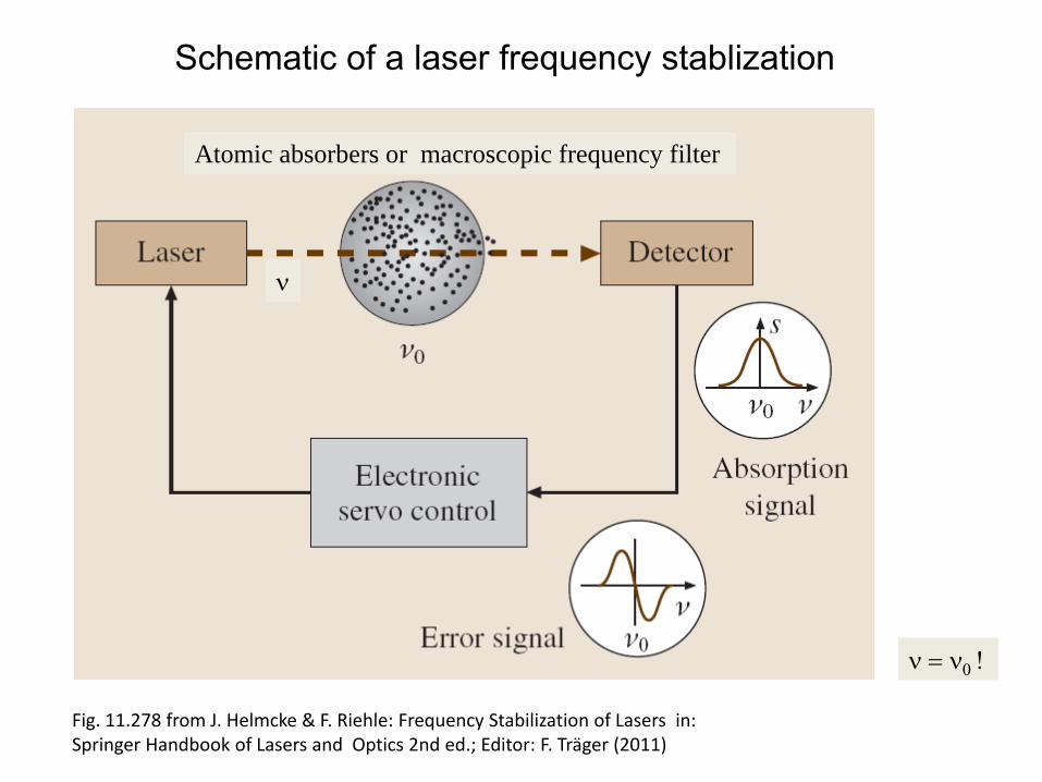
Schematic of a laser frequency stablization
Fig. 11.278 from J. Helmcke & F. Riehle: Frequency Stabilization of Lasers in: Springer Handbook of Lasers and Optics 2nd ed.; Editor: F. Träger (2011)
Atomic absorbers or macroscopic frequency filter
ν
ν = ν0 !
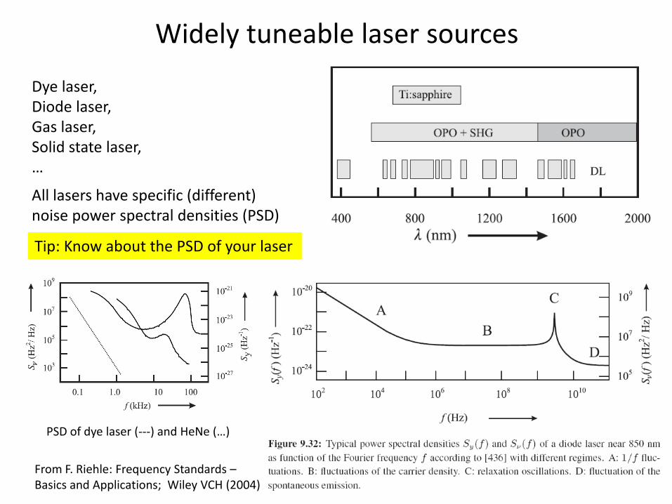
Widely tuneable laser sources
Dye laser,Diode laser,Gas laser,Solid state laser,…
All lasers have specific (different) noise power spectral densities (PSD)
Tip: Know about the PSD of your laser
From F. Riehle: Frequency Standards –Basics and Applications; Wiley VCH (2004)
PSD of dye laser (‐‐‐) and HeNe (…)
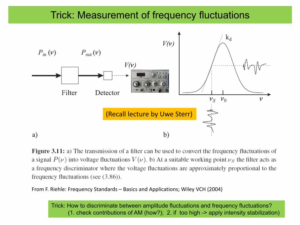
Trick: Measurement of frequency fluctuations
From F. Riehle: Frequency Standards – Basics and Applications; Wiley VCH (2004)
(Recall lecture by Uwe Sterr)
Trick: How to discriminate between amplitude fluctuations and frequency fluctuations?(1. check contributions of AM (how?); 2. if too high -> apply intensity stabilization)
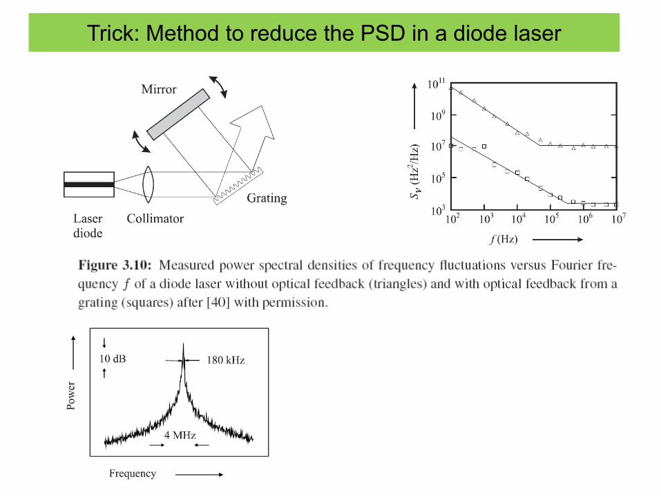
Trick: Method to reduce the PSD in a diode laser
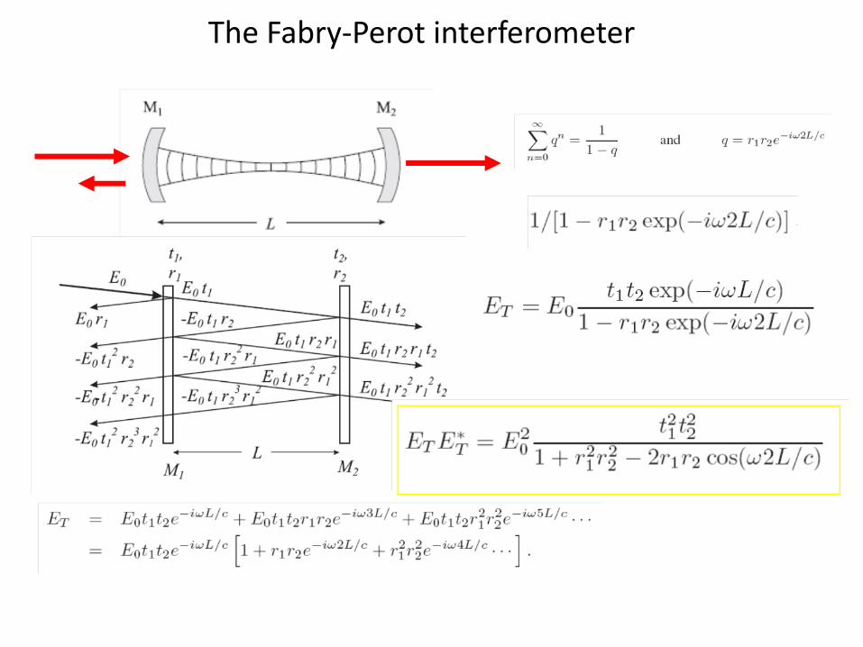
The Fabry‐Perot interferometer
The Fabry-Perot interferometer
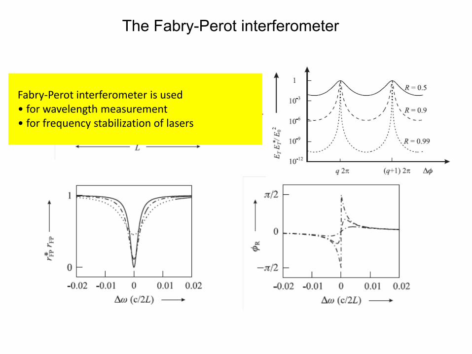
Fabry‐Perot interferometer is used• for wavelength measurement• for frequency stabilization of lasers
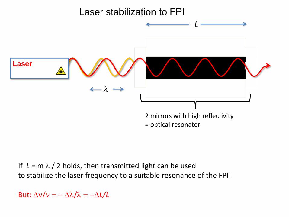
Laser stabilization to FPI
If L = m λ / 2 holds, then transmitted light can be usedto stabilize the laser frequency to a suitable resonance of the FPI!
But: Δν/ν = − Δλ/λ = −ΔL/L
Laser
2 mirrors with high reflectivity= optical resonator
L
λ
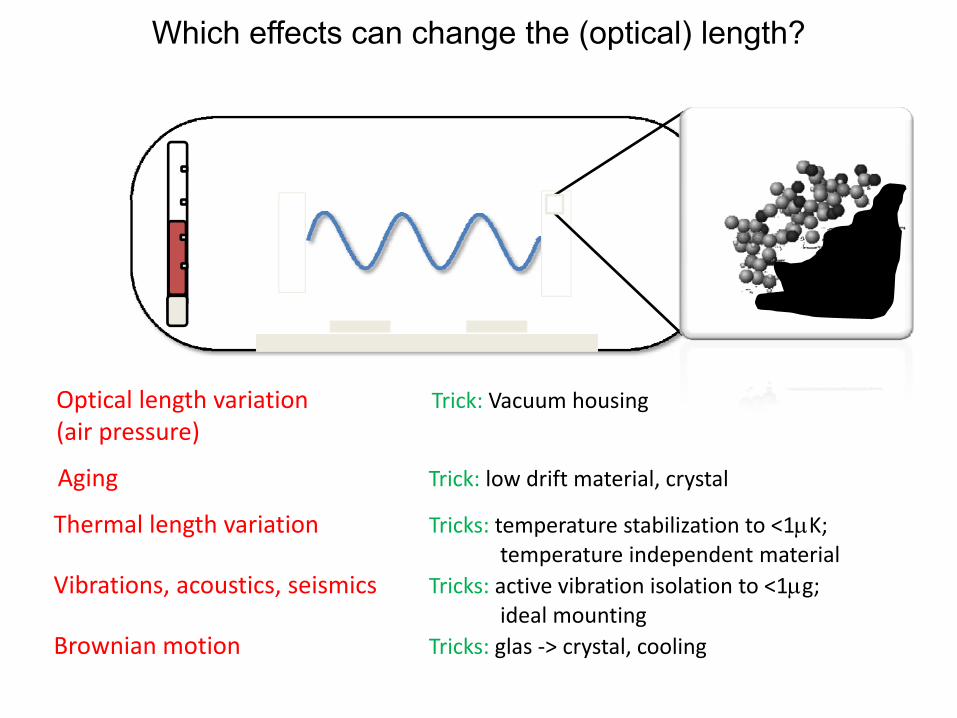
Which effects can change the (optical) length?
Thermal length variation Tricks: temperature stabilization to <1μK; temperature independent material
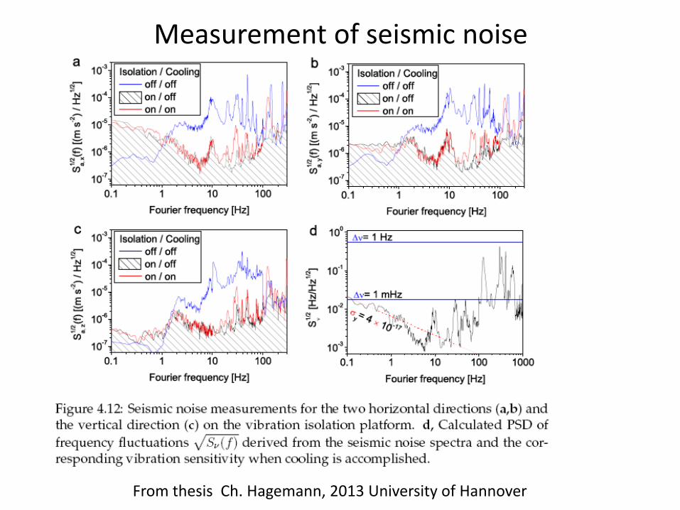
Vibrations, acoustics, seismics Tricks: active vibration isolation to <1μg;ideal mounting
From thesis Ch. Hagemann, 2013 University of Hannover
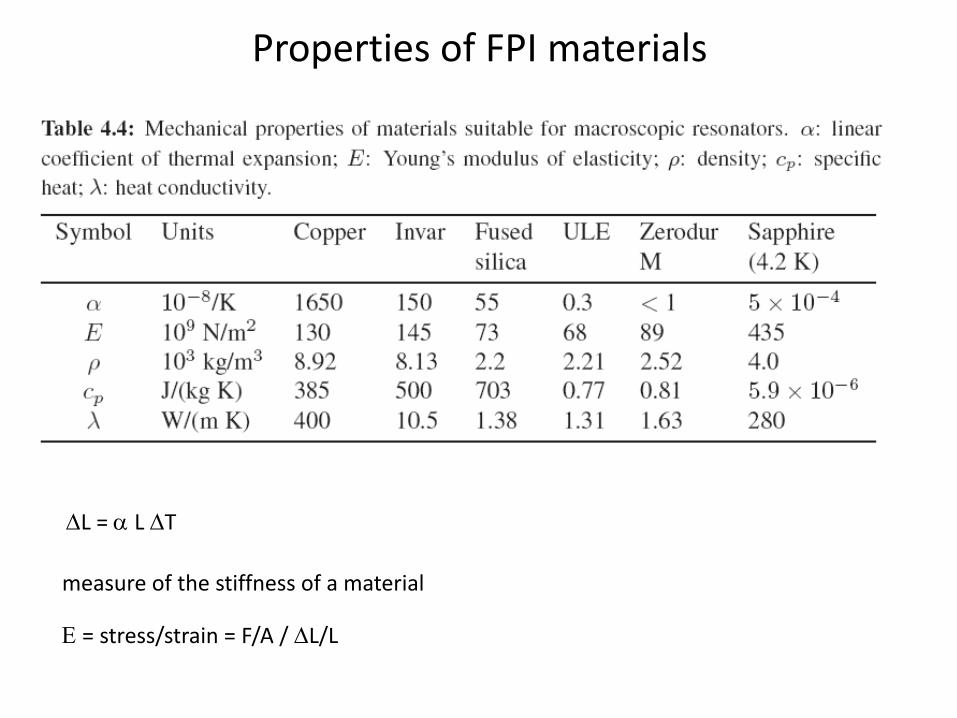
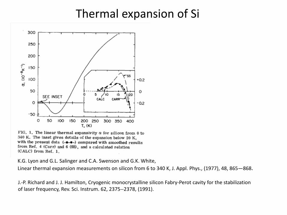
Thermal expansion of Si
K.G. Lyon and G.L. Salinger and C.A. Swenson and G.K. White,Linear thermal expansion measurements on silicon from 6 to 340 K, J. Appl. Phys., (1977), 48, 865—868.
J.‐P. Richard and J. J. Hamilton, Cryogenic monocrystalline silicon Fabry‐Perot cavity for the stabilization of laser frequency, Rev. Sci. Instrum. 62, 2375‐‐2378, (1991).
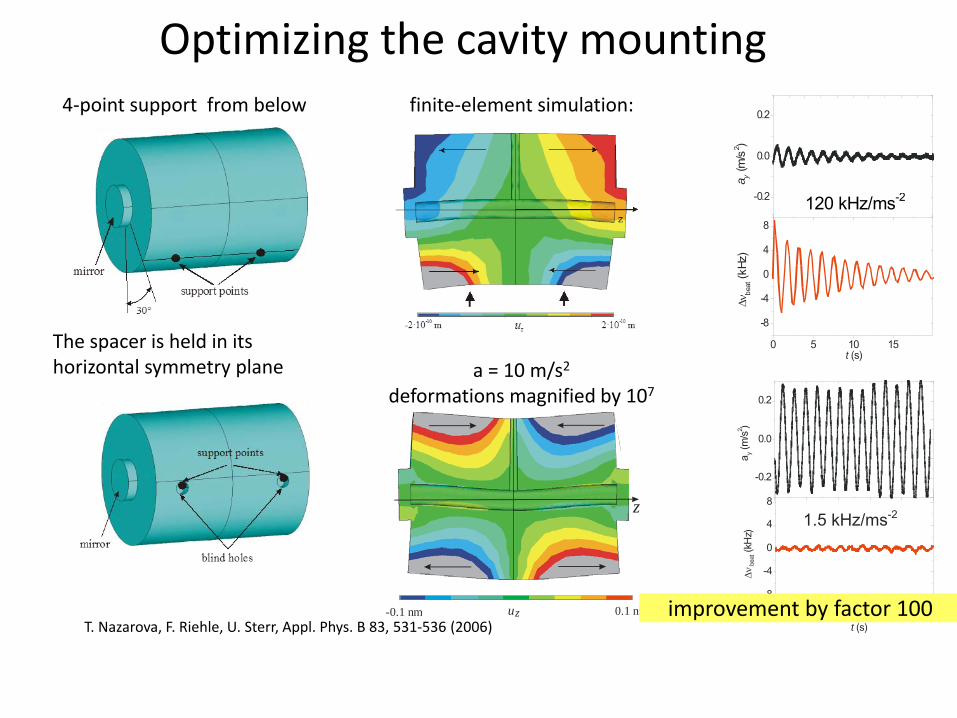
4‐point support from below
Optimizing the cavity mountingfinite‐element simulation:
a = 10 m/s2deformations magnified by 107
-0.1 nm 0.1 nmuz
z
The spacer is held in its horizontal symmetry plane
T. Nazarova, F. Riehle, U. Sterr, Appl. Phys. B 83, 531‐536 (2006)
0 1 2 3 4 5
-0.2
0.0
0.2
0 2 4 6 8 10
-0.3
-0.2
-0.1
0.0
0.1
0.2
0.3
a y(m
/s2 )
0 1 2 3 4 5
-8
-4
0
4
8
-8
-4
0
4
8
Δνbe
at(k
Hz)
t (s)
1.5 kHz/ms-2
improvement by factor 100
0 5 10 15
-0.2
0.0
0.2
-0.3
-0.2
-0.1
0.0
0.1
0.2
0.31 2 3 4 5 6
a y(m
/s2 )
0 5 10 15
-8
-4
0
4
8
-8
-4
0
4
8
t (s)
Δνbe
at(k
Hz)
120 kHz/ms-2
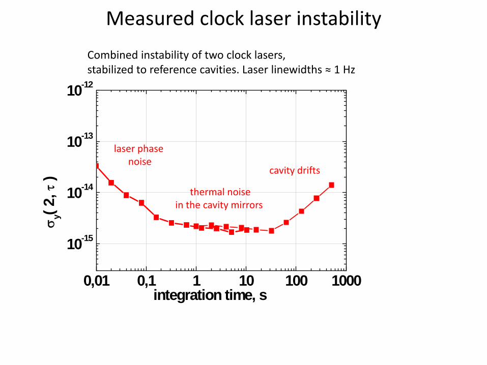
Measured clock laser instabilityCombined instability of two clock lasers, stabilized to reference cavities. Laser linewidths ≈ 1 Hz
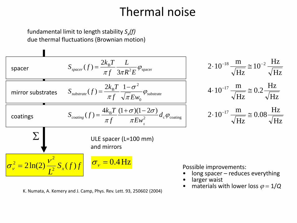
K. Numata, A. Kemery and J. Camp, Phys. Rev. Lett. 93, 250602 (2004)
HzHz10
Hzm102 218 −− ≅⋅
HzHz2.0
Hzm104 17 ≅⋅ −
HzHz08.0
Hzm102 17 ≅⋅ −
ffSL x )()2ln(2 2
22 νσν = Hz4.0=νσ
ULE spacer (L=100 mm) and mirrors
Σ
spacer2B
32)( ϕ
ππ ERL
fTkfSspacer =
coatingc2B
0
)21)(1(4)( ϕπ
σσπ
dEwf
TkfScoating−+
=
substrate0
2B 12)( ϕ
πσ
π wEfTkfSsubstrate
−=
spacer
mirror substrates
coatings
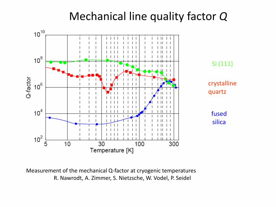
Possible improvements:• long spacer – reduces everything • larger waist• materials with lower loss ϕ = 1/Q
Mechanical line quality factor Q
Si (111)
fusedsilica
crystallinequartz
Measurement of the mechanical Q‐factor at cryogenic temperatures R. Nawrodt, A. Zimmer, S. Nietzsche, W. Vodel, P. Seidel
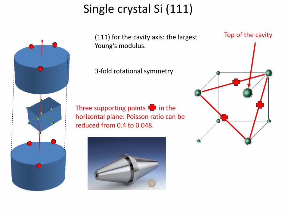
Single crystal Si (111)
(111) for the cavity axis: the largest Young’s modulus.
3‐fold rotational symmetry
Three supporting points in the horizontal plane: Poisson ratio can be reduced from 0.4 to 0.048.
Top of the cavity
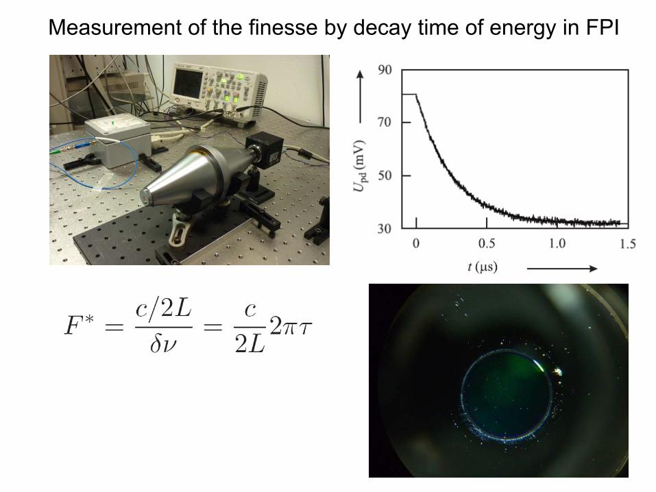
Measurement of the finesse by decay time of energy in FPI
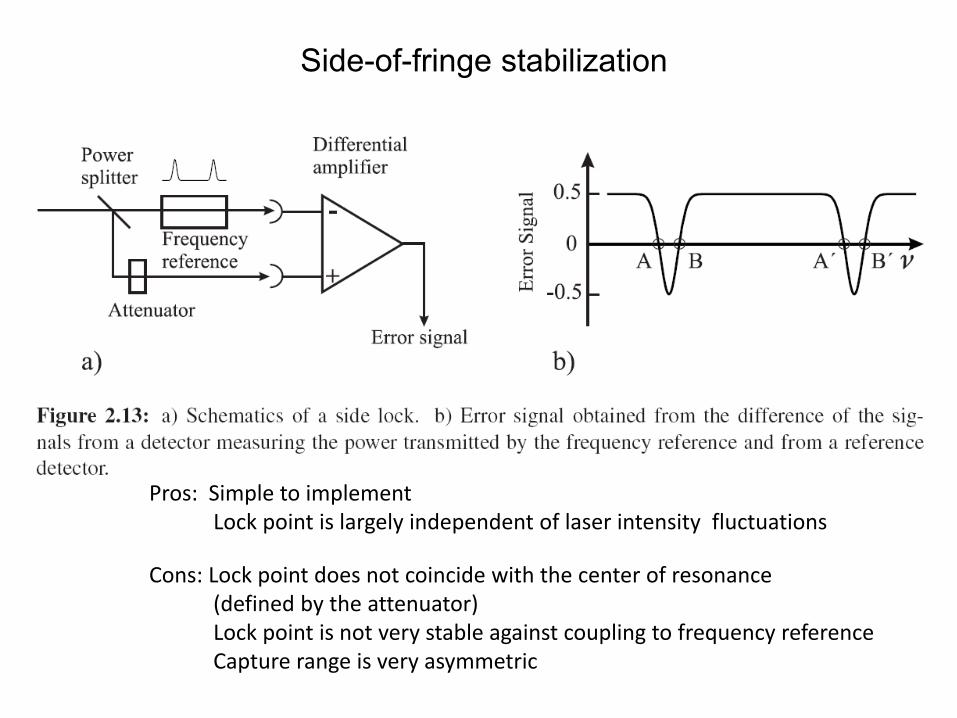
Side-of-fringe stabilization
Pros: Simple to implementLock point is largely independent of laser intensity fluctuations
Cons: Lock point does not coincide with the center of resonance(defined by the attenuator)Lock point is not very stable against coupling to frequency referenceCapture range is very asymmetric
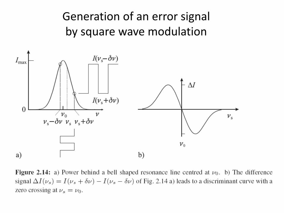
Generation of an error signal by square wave modulation
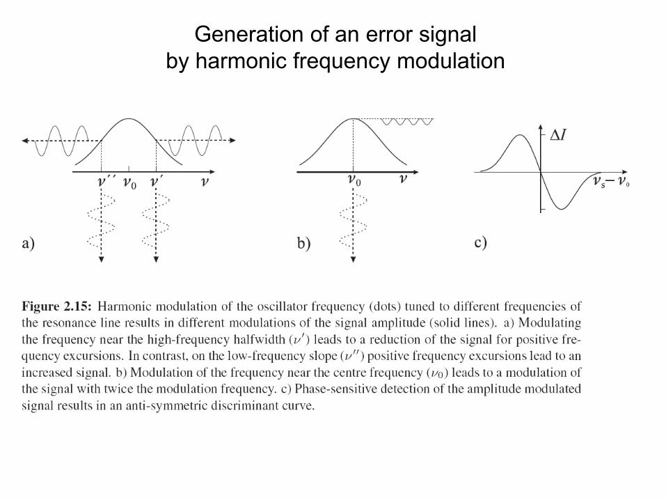
Generation of an error signalby harmonic frequency modulation
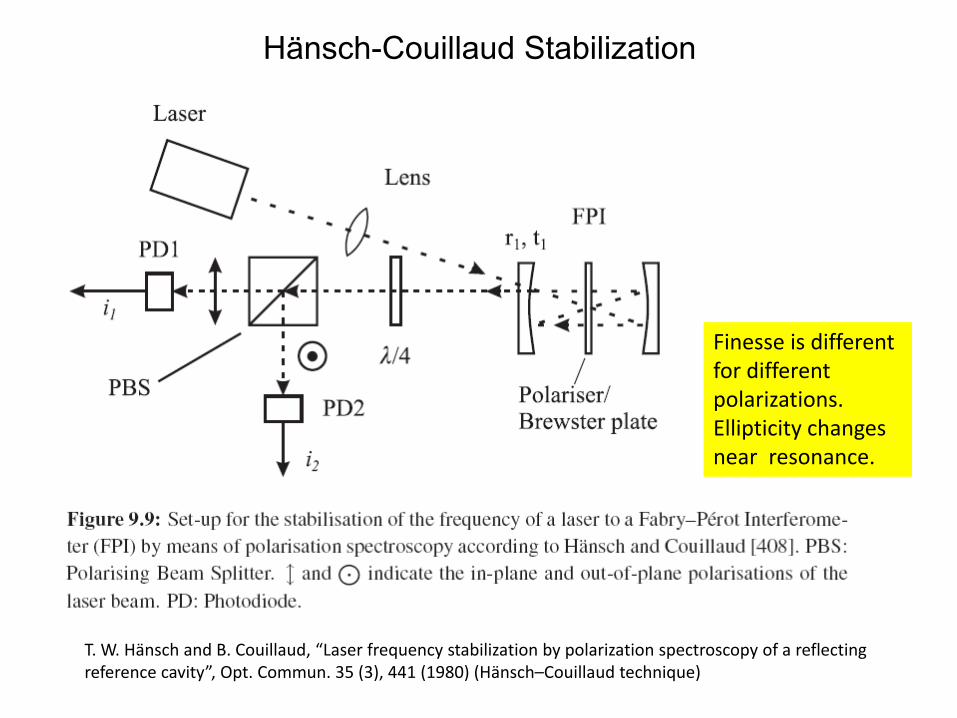
Hänsch-Couillaud Stabilization
T. W. Hänsch and B. Couillaud, “Laser frequency stabilization by polarization spectroscopy of a reflectingreference cavity”, Opt. Commun. 35 (3), 441 (1980) (Hänsch–Couillaud technique)
Finesse is different for different polarizations.Ellipticity changesnear resonance.
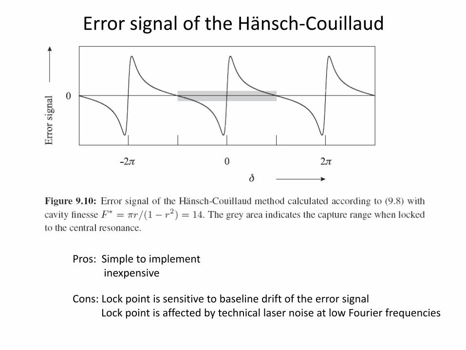
Error signal of the Hänsch‐Couillaud
Pros: Simple to implementinexpensive
Cons: Lock point is sensitive to baseline drift of the error signalLock point is affected by technical laser noise at low Fourier frequencies
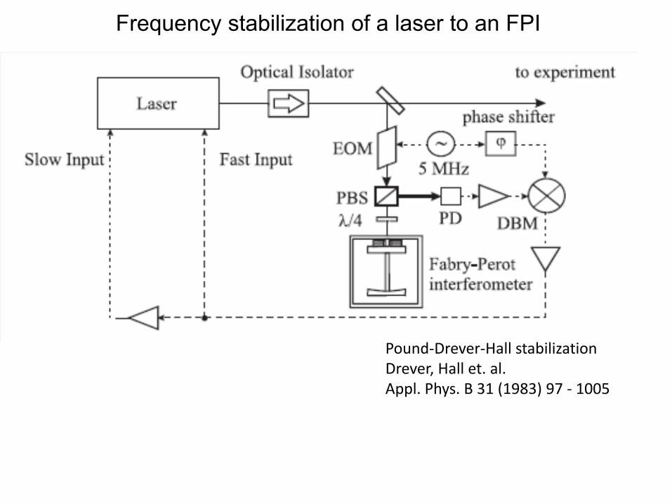
Frequency stabilization of a laser to an FPI
Pound‐Drever‐Hall stabilizationDrever, Hall et. al. Appl. Phys. B 31 (1983) 97 ‐ 1005
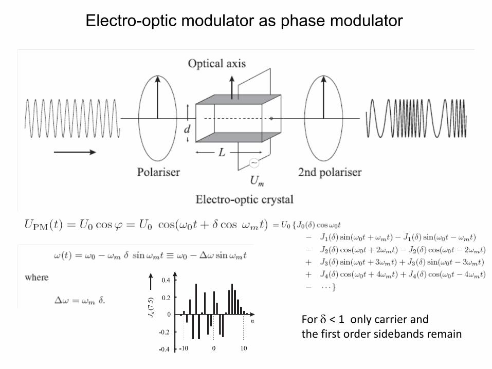
Electro-optic modulator as phase modulator
For δ < 1 only carrier andthe first order sidebands remain
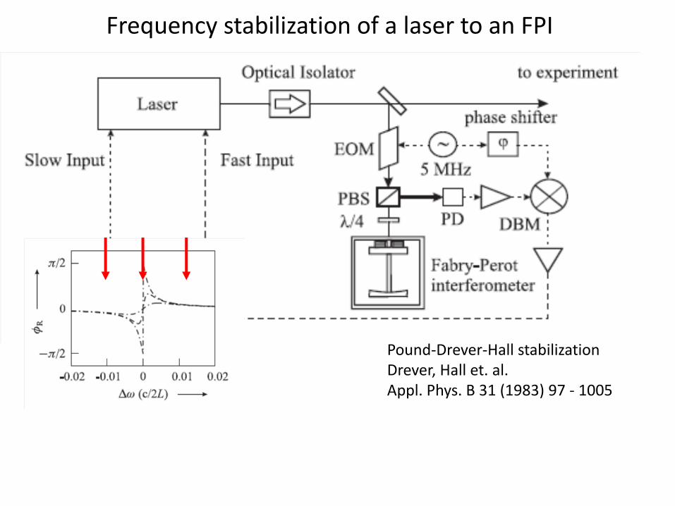
Frequency stabilization of a laser to an FPI
Pound‐Drever‐Hall stabilizationDrever, Hall et. al. Appl. Phys. B 31 (1983) 97 ‐ 1005
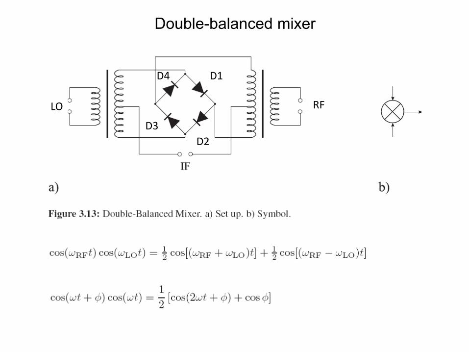
Double-balanced mixer
LO RF
D2
D1
D3
D4
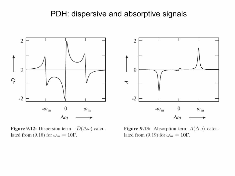
PDH: dispersive and absorptive signals
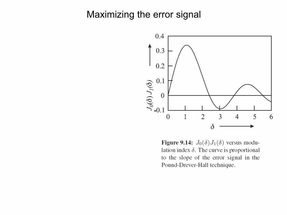
Maximizing the error signal
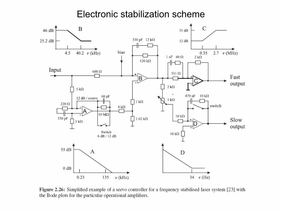
Electronic stabilization scheme
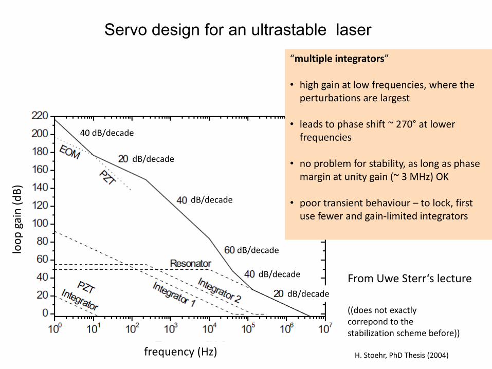
Servo design for an ultrastable laser
H. Stoehr, PhD Thesis (2004) frequency (Hz)
loop
gain (dB)
40 dB/decade
dB/decade
dB/decade
dB/decade
dB/decade
dB/decade
“multiple integrators”
• high gain at low frequencies, where the perturbations are largest
• leads to phase shift ~ 270° at lower frequencies
• no problem for stability, as long as phase margin at unity gain (~ 3 MHz) OK
• poor transient behaviour – to lock, first use fewer and gain‐limited integrators
From Uwe Sterr‘s lecture
((does not exactlycorrepond to thestabilization scheme before))
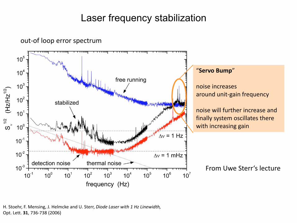
Laser frequency stabilization
H. Stoehr, F. Mensing, J. Helmcke and U. Sterr, Diode Laser with 1 Hz Linewidth,Opt. Lett. 31, 736‐738 (2006)
“Servo Bump”
noise increasesaround unit‐gain frequency
noise will further increase and finally system oscillates there with increasing gain
out‐of loop error spectrum
From Uwe Sterr‘s lecture
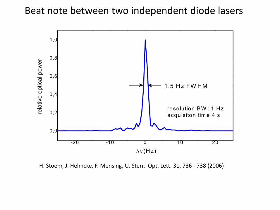
Beat note between two independent diode lasers
-20 -10 0 10 20
0,0
0,2
0,4
0,6
0,8
1,0
1.5 Hz FW HM
rela
tive
optic
al p
ower
Δν (Hz)
resolution BW : 1 Hzacquisiton tim e 4 s
H. Stoehr, J. Helmcke, F. Mensing, U. Sterr, Opt. Lett. 31, 736 ‐ 738 (2006)
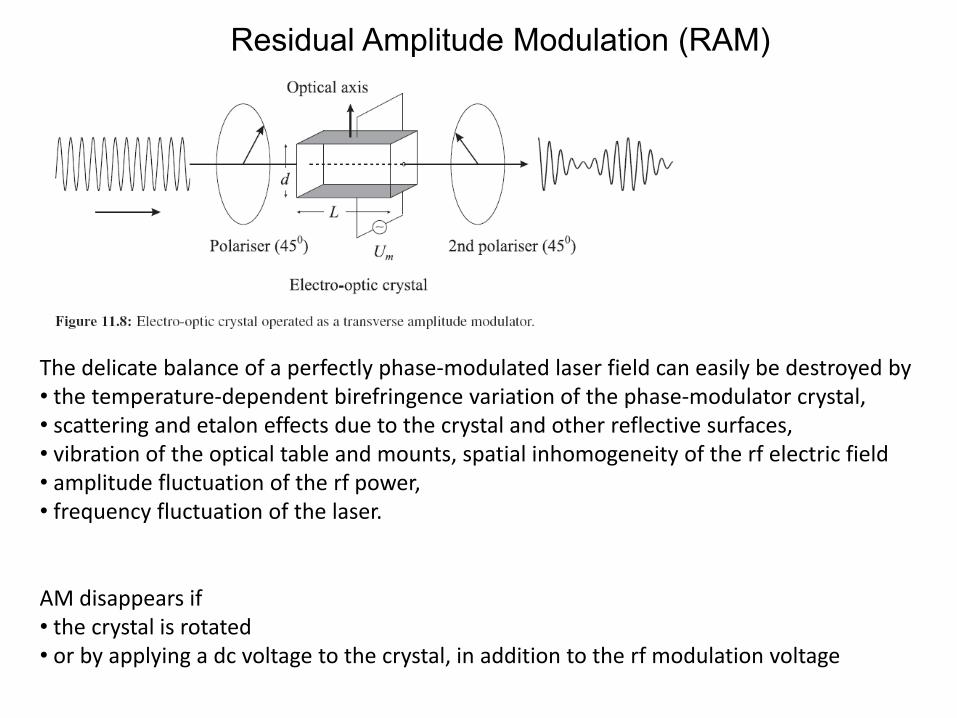
Residual Amplitude Modulation (RAM)
The delicate balance of a perfectly phase‐modulated laser field can easily be destroyed by• the temperature‐dependent birefringence variation of the phase‐modulator crystal, • scattering and etalon effects due to the crystal and other reflective surfaces,• vibration of the optical table and mounts, spatial inhomogeneity of the rf electric field• amplitude fluctuation of the rf power,• frequency fluctuation of the laser.
AM disappears if• the crystal is rotated• or by applying a dc voltage to the crystal, in addition to the rf modulation voltage
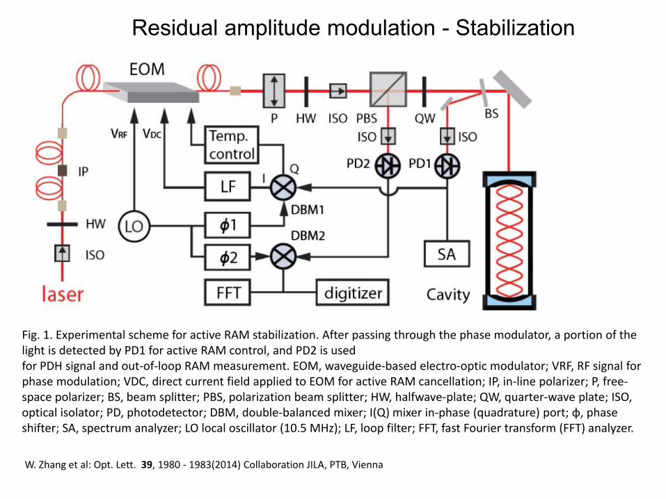
Residual amplitude modulation - Stabilization
Fig. 1. Experimental scheme for active RAM stabilization. After passing through the phase modulator, a portion of the light is detected by PD1 for active RAM control, and PD2 is usedfor PDH signal and out‐of‐loop RAM measurement. EOM, waveguide‐based electro‐optic modulator; VRF, RF signal for phase modulation; VDC, direct current field applied to EOM for active RAM cancellation; IP, in‐line polarizer; P, free‐space polarizer; BS, beam splitter; PBS, polarization beam splitter; HW, halfwave‐plate; QW, quarter‐wave plate; ISO, optical isolator; PD, photodetector; DBM, double‐balanced mixer; I(Q) mixer in‐phase (quadrature) port; φ, phaseshifter; SA, spectrum analyzer; LO local oscillator (10.5 MHz); LF, loop filter; FFT, fast Fourier transform (FFT) analyzer.
W. Zhang et al: Opt. Lett. 39, 1980 ‐ 1983(2014) Collaboration JILA, PTB, Vienna
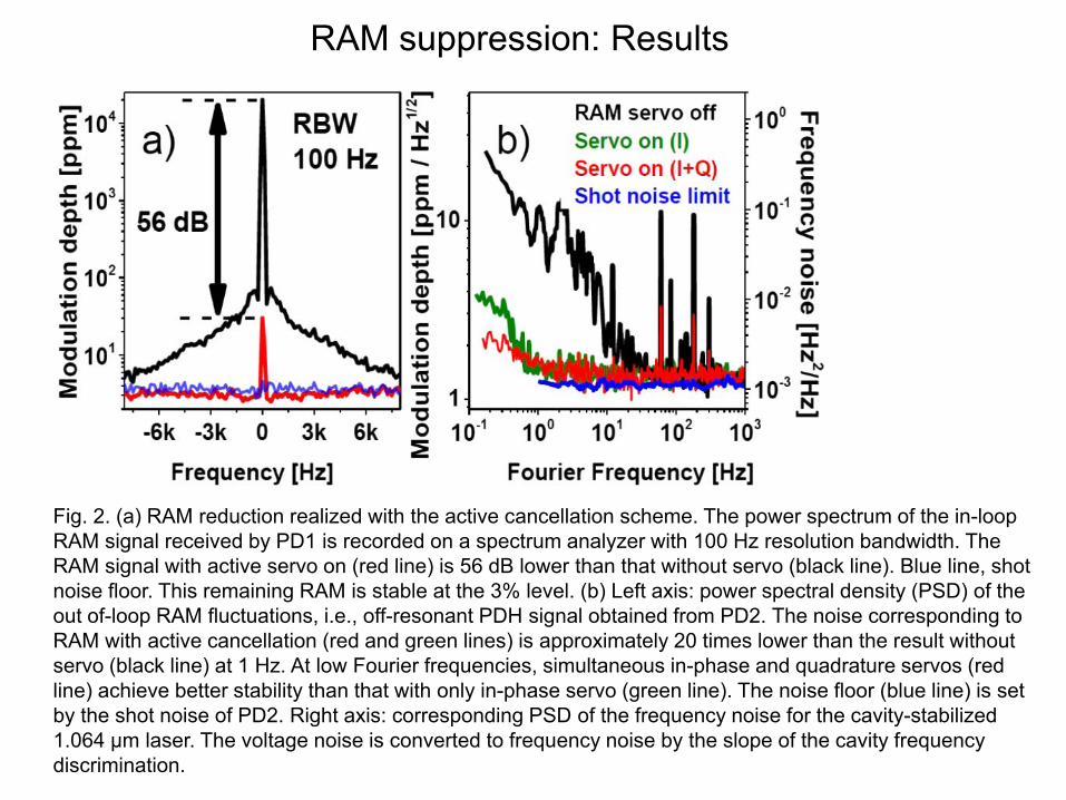
RAM suppression: Results
Fig. 2. (a) RAM reduction realized with the active cancellation scheme. The power spectrum of the in-loop RAM signal received by PD1 is recorded on a spectrum analyzer with 100 Hz resolution bandwidth. The RAM signal with active servo on (red line) is 56 dB lower than that without servo (black line). Blue line, shot noise floor. This remaining RAM is stable at the 3% level. (b) Left axis: power spectral density (PSD) of the out of-loop RAM fluctuations, i.e., off-resonant PDH signal obtained from PD2. The noise corresponding to RAM with active cancellation (red and green lines) is approximately 20 times lower than the result without servo (black line) at 1 Hz. At low Fourier frequencies, simultaneous in-phase and quadrature servos (red line) achieve better stability than that with only in-phase servo (green line). The noise floor (blue line) is set by the shot noise of PD2. Right axis: corresponding PSD of the frequency noise for the cavity-stabilized 1.064 μm laser. The voltage noise is converted to frequency noise by the slope of the cavity frequencydiscrimination.
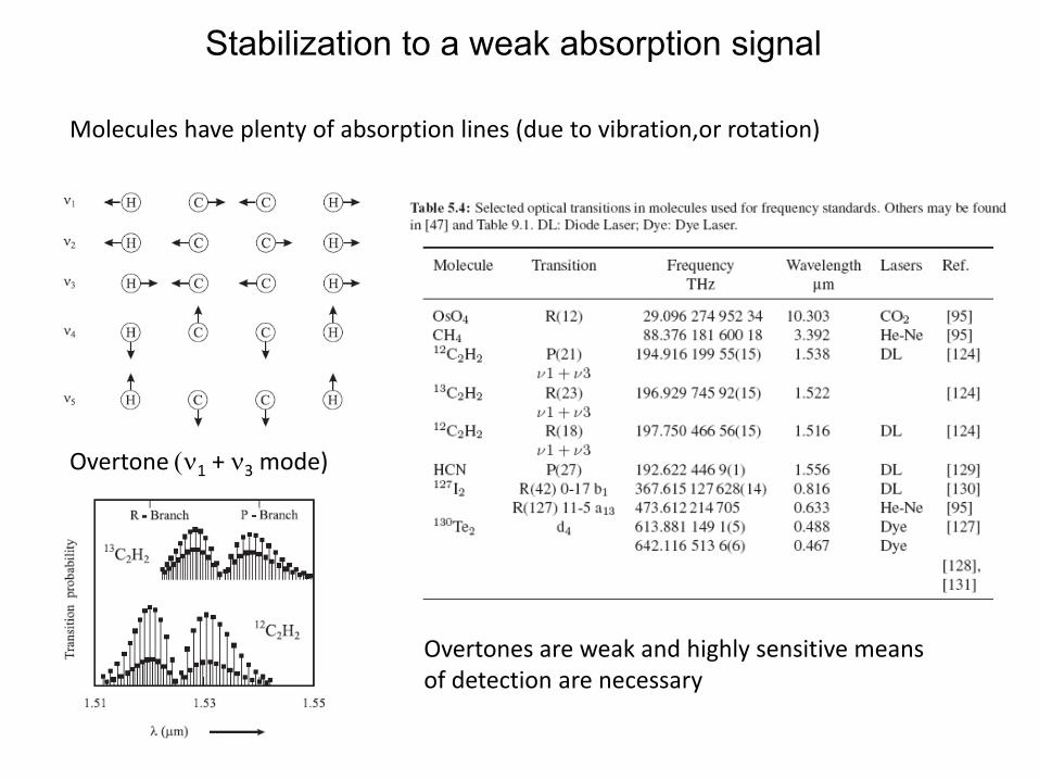
Stabilization to a weak absorption signal
Overtone (ν1 + ν3 mode)
Molecules have plenty of absorption lines (due to vibration,or rotation)
Overtones are weak and highly sensitive meansof detection are necessary
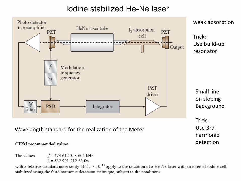
Iodine stabilized He-Ne laser
Wavelength standard for the realization of the Meter
weak absorption
Trick: Use build‐upresonator
Small lineon slopingBackground
Trick: Use 3rd harmonicdetection
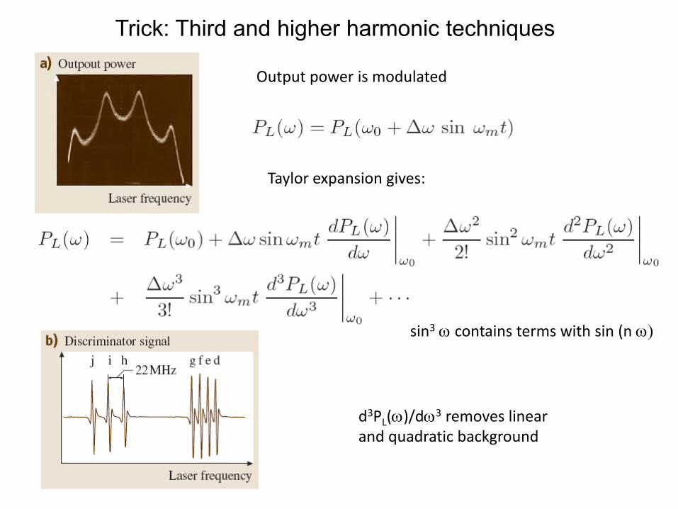
Trick: Third and higher harmonic techniques
Taylor expansion gives:
Output power is modulated
sin3 ω contains terms with sin (n ω)
d3PL(ω)/dω3 removes linear and quadratic background
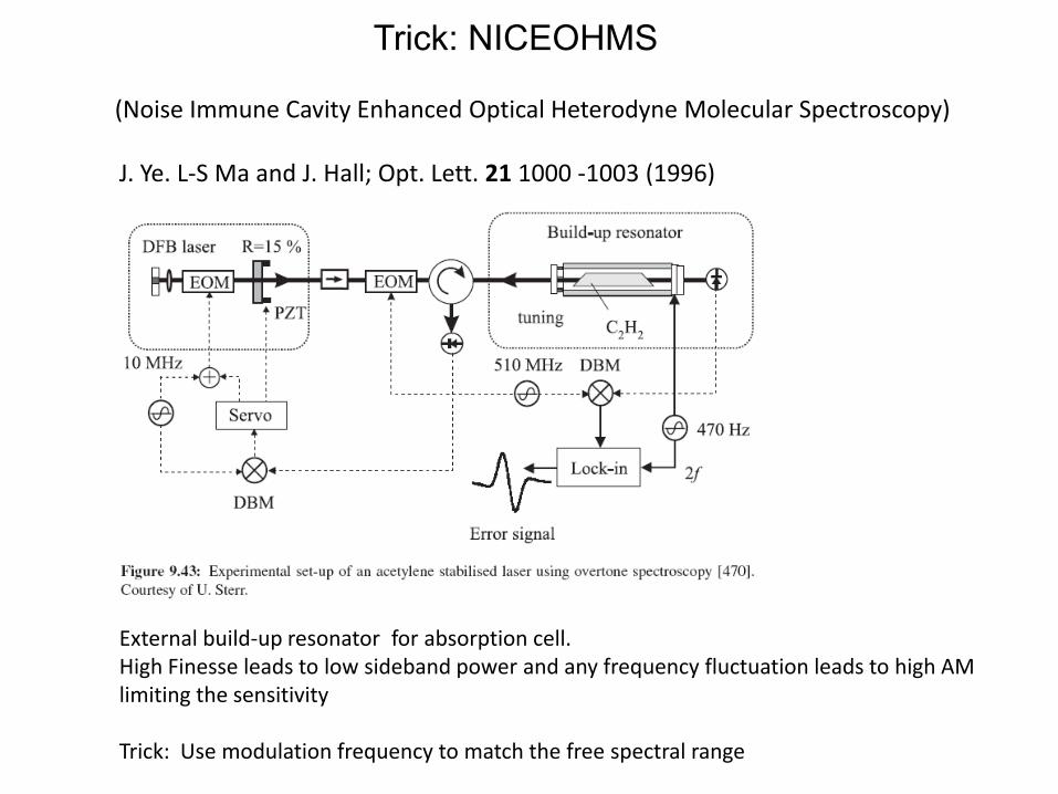
J. Ye. L‐S Ma and J. Hall; Opt. Lett. 21 1000 ‐1003 (1996)
External build‐up resonator for absorption cell. High Finesse leads to low sideband power and any frequency fluctuation leads to high AMlimiting the sensitivity
Trick: Use modulation frequency to match the free spectral range
Tips
Fritz Riehle; Lecture: June 5, 2014
• Principle• T&T: Noise spectrum of the laser
• Frequency Stabilization to a Fabry‐Perot Interferometer (FPI)• Principle of FPI
• T&T: Preparation, noise‐free mount; measurement of finesse• Side‐of‐Fringe Lock


![Introduction of AIM/Impact[Policy] · concentration) stabilization scenario 9Equilibrium temperature increase of approx. 2.9ºC (compared with pre industrial period; approx. 2.7ºC](https://static.documents.pub/doc/80x56/5e8a292efc2a0051241754bf/introduction-of-aimimpactpolicy-concentration-stabilization-scenario-9equilibrium.jpg)


