1-481-71-83 W5lAl m x'l jsX12 TIROS-M/ITOS MOMENTUM-WHEEL ASSEMBLY (MWA) REPORT MARCH 1971 SPACE FLIGHT C S-GODDARD GREENBELT, MARYLAND O' ((CODE) (CATEORY) X OR AD NUMBR) S(NASA CRR https://ntrs.nasa.gov/search.jsp?R=19710016170 2020-04-04T05:10:53+00:00Z
The momentum-wheel assembly (MWA) as part of a three-axis system to stabilize the TIROS-iMITOS spacecraft to a pointing accuracy of less than 1 degree in all three axes The MWA was vigorously tested during its design period, then several units were successfully life tested in thermal vacuum for approximately 6 months During spacecraft tests of TIROS-M, excessive brush wear developed with one of the redundant motors (motor 2), but the condition corrected itself and the MWA was considered to be flhghtworthy. During in-orbit engineering evaluation tests, additional excessive brush wear was attributed to inadequate thermal control of motor 2 Analysis and testing showed that installation of a heater would reduce the wear rate and ensure motor redundancy ITOS-A, B, and C MWA's include this modification.
III
PR20CEDNG PAGE BLANK NOT FILMED
CONTENTS
Page
ABSTRACT .... .. .. .. .... . in
INTRODUCTION .. .. .. .... . 1
EARLY DESIGN AND DEVELOPMENT ...... . . . . . . ... 1
DESIGN FOR THE TIROS-M/ITOS PROGRAM . . ......... 1
Conversion to the Redundant Motor Configuration .. . . . . ... 1
Life Tests .................. .............. 37
MWA Flight Unit SN06 (TIROS-M/ITOS-1) Acceptance Tests . 43
MWA SN06 Performance in Orbit ............. .... 45
MODIFICATION TO ENSURE MOTOR REDUNDANCY ........ 46
ITOS-i MWA SNO6 Motor 2 Failure Analysis . ......... 46
Heater Modification ..... ........ ........... 57
CONCLUSION ........ ........... ............ 62
REFERENCES ....... ............ ........... 66
SOURCES ......... ............ ........... 67
v
ILLUSTRATIONS
Figure Page
Fronhspiece Artist's Conception of ITOS Spacecraft....... . . x
42 MWA SNO4 Temperatures and Heater Power During ITOS-A Thermal-Vacuum Tests ..... ... ..... 64
43 ITOS-1 MWA Brush Wear and Temperature ......... ... 65
vi
Frontispiece. Artist's Conception of ITOS Spacecraft
TABLES
Table Page
1 MWA-SN02P Operating History ....... 7
2 MWA Brash Wear Data .......... 9
3 MWA Prototype Test Results (as of November 1968) 14
4 TIROS-M MWA Test History (as of February 1969). 16
5 MWA Static Thermal Test Data .. .... ......... 21
6 MWA Development Test Results ...... .......... 22
7 Modified MWA Thermal Design (comparison of SNO5 with computer model) ......... ............... .. 36
8 MWA Brash Wear Results from Life Tests .... ...... .. 39
9 MWA SN02P Dynamic Tests, Flange-Heater Test Results ............ ................ .. .. 56
10 Second Series of Dynamic Tests ..... ............ .. 58
11 Summary of MWA SN02P Dynamic Heater Tests ....... .. 60
12 Heater Combinations and Expected Use ...... ......... 62
ix
INTRODU CTION
The momentum wheel assembly (MWA) is part of a three-axes stabilization systern which stabilizes the TIROS-M/ITOS spacecraft to a pointing accuracy of less than 1 degree in all three axes. The system includes an inertia wheel, redundant brush motors, and associated electronics.
The TIROS-M/ITOS MWA is an outgrowth of a single brush motor design developed in-house by RCA/AED, The 50/50 silver graphite brusheswerelubricated with a diester, dioctyl adipate, impregnated in a nylasint reservoir. This early single motor MWA was reconfigured for the TIROS-M/ITOS program to a redundant brush motor design for increased reliability. Afterthe design was changed from single motor to dual motor, the lubricant was changed to Bendix P-10 oil and additional nylasint reservoirs were installed This change to dual motors introduced adverse thermal conditions which were analyzed and tested in detail Subsequently, several MWAs successfully operated for 6 months in thermal vacuum. During the TIROS-M thermal-vacuum acceptance test, excessive brush wear occurred on one of the redundant motors (motor 2). As a result of an investigation, the brush wear was attributed to overtesting. Because the condition corrected itself, the MWA was considered flightworthy. During the performance of the TEROS-M (ITOS 1) MWA in orbit, the motor 2 brushes wore out because of inadequate thermal control in the motor 2 area. To fullfill motor redundancy requirements, heaters must be installed on brush-type MWA's on future spacecraft.
EARLY DESIGN AND DEVELOPMENT
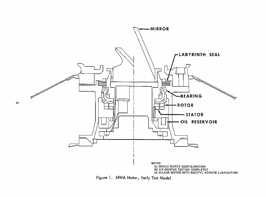
Figure 1 shows the intial single-motor MWA developed by RCA/AED. The MWA uses a single bearing to connect the stabilized body and the inertia wheel (powered by an Inland brush-type torque motor) The 50/50 silver graphite brushes and the bearing have been lubricated with a diester, dioctyl adipate, impregnated in a nylasint reservoir. A labryinth seal controls the effluence of the oil vapor given off by the oil reservoir. Dioctyl adipate has a high vapor pressure (about 10 - 4 Torr at +25 C), ensuring that an adequate amount of lubricant is avwalable. In 1966, a 6-month thermal-vacuum lfe test of this design over the temperature range 00 C to 200 C at less than 10 -5 Torr resulted in a very low oil loss and brush wear of 2 mil.
DESIGN FOR THE TIROS-M/ITOS PROGRAM
Conversion to the Redundant Motor Configuration
The success of the MWA single-motor design and the Inland brush-type motor led to the adoption of a similar design for the TIROS-M/ITOS spacecraft using
1
MIRROR
LABYRINTH SEAL
0 0
ID ROTOR
- - STATOR
OIL RESERVOIR
NOTES (a)SINGLE MOTOR CONFIGURATION (b) SIX MONTHS TESTING COMPLETED (c) INLAND MOTOR WITH DIOCTYL ADIPATE LUBRICATION
Figure 1. MWA Motor, Early Test Model
redundant brush motors This configuration (Figure 2) retained the singlebearing concept Figure 3 shows the location of the MWA on the spacecraft The new design has two labyrinth seals (Figure 2), and the lubricant and reservoir material are the same as before Housing and shaft material are titamum for weight mimnzation and thermal control. 1 The wheel assembly is magnesium, except for the fiberglass spokes and aluminum rim of the inertia wheel Motor 1 is nearest the inertia wheel and motor 2 is at the encoder end. Each motor is an Inland, type 4437A 2 and is nominally operated at 150 rpm Each motor requires approximately 2 7 watts to operate (in gravity field) Only one motor is powered at a time (the circuitry design enables both motors to operate simultaneously). Peak torque output of each motor with rated output current applied to the armature is 1 pound-foot. Shaft torque is designed to be 20oz-in at 150 rpm
A 6-month life test was initiated to demonstrate that the two-motor configuration would satisfy mission requirements The life test was scheduled for August 1968 Table 1 lists the prequalification tests performed before the life test. Figure 4 shows the thermal-vacuum test configuration for the prequalification part of these tests., At the end of the last test in Table 1, MWA SN02P was disassembled and anspected: motor I brushes were completely worn out and the surrounding area was dry; whereas, motor 2 brushes had worn 6to 9 nils and the surrounding area was wet Reservoir loss measured 3 grams of the 44 grams of dioctyle adipate lubricant Excessive brush wear was attributed to marginal lubrication and inefficient dispersion of the oil within the MWA. Additional oil reservoirs were installed on the side of each brush motor facing the labyrinth seal and through-holes were drilled between each chamber (e. g either side of the bearing in Figure 2) to both increase and equalize saturation-vapor pressure within the MWA
To ensure that the foregoing modifications were satisfactory before the life test began, two tests were performed repetition of the failure mode under the same environmental conditions using another MWA configured exactly like SN02P, and modification of the SN02P and a retest in the environmental conditions under which it had previously failed MWA SN03 was selected for the first test and MWA SN02P (reworked with new motor brushes) for the second test. The units were instrumented to obtain temperature data.
To monitor motor brush wear in real time, the SN02P (reworked), MWA includes a brush-wear detection device consisting of a bridge circuit which has two strain gauge resistors on the top and bottom of the brush arm and two resistors on the outside MWA housing (Figure 5). As the brushes wear, a bridge network senses the change in voltage calibrated to correspond to mils of brush-height reduction The resulting data is the brush reserve.
Table 2 lists brush wear from the SN02P, SN03, and SN02P (reworked) MWA tests performed in thermal vacuum. The first brush-wear data is a result of tests performed on SN02P (Table 1). An unsuccessful attempt to repeat the first test failure resulted in maximum brush wear on motor 2 instead of motor I '(SN03 m Table 2). The last test (in which end oil reservoirs were added to the MWA) showed improved lubricating conditions, but resulting wear rates were still too high to meet mission requirements of 6 months and a design goal of 1 year.
No applicable brushless-motor substitutes were found in an investigation of brushless motors available for space application begun simultaneously with the analysis of the excessive brush-wear condition. As a result, GSFC directed the contractor to start a parallel prototype brushless-motor development to qualify a flight unit to phase in to the spacecraft program if MWA brush wear could not be significantly reduced.
5
BELL JAR SHROUD (Brine Solution)
DUMMY FLYWHEEL
MOUNTING FLANGE
MAIN RESEVOIR
MWAnAN
ELECTRONICS ""' MOTOR 2
ILABYRItTHSEAL
i _ '-J- ENCODER
FTCgur .iXTURE
Figure 4. Thermal-Vacuum Test in Bell Jar Configuration
OR1 AND R2 LOCATED ON THE TOP AND BOTTOM OF THE BRUSH ARM
*R3 AND R4 LOCATED ON THE OUT-SIDE OF THE MWA HOUSING
Figure 5. Brush Wear Defection Device
At the same time, the project reviewed previous tests, test conditions, brush characteristics, and lubrication conditions. The brush manufacturer provided a history of the characteristics of the brush material on MWA's SN02P and SNOS and the method of selecting brush material.3, 4 The brush parameters were within the specified tolerances (brush material and specifications were sinlar to those for the Orbiting Solar Observatory (OSO) program). Reference 5 summarized MWA history to this time.
Early in the ITOS program, a bearing life test was planned which would test 12 bearings In the proper lubrication environment during thermal vacuum. For economic reasons, tins test was to be performed in the same vacuum chamber as the 1VWA 6-month life test. The combination test fixture created an environment for the life-test unit that kept both motors at virtually the same temperature instead of the desired 7°C gradient (70C obtained by analysis). This temperature gradient was considered unrealistic for motor 2 (i. e., motor 2 would be cooler than normal) Installation of a strip heater around the housing at motor 2 level (Figure 6) resolved the problem. The MWA tested was SN02P, which had the adcitional end oil reservoirs. Figures 7 and 8 are plots of the motor temperature and brush wear data from this test in thermal vacuum. The temperature gradient between motors was approximately +10°C, and brush wear was very high Figure 9 shows the similar results that occurred when the same MWA operated at +250C Motor 2 was powered and also indicated excessive brush wear. Temperature data showed an 180 C gradient between motors. Table 3, a summation of all MWA test results to data, shows no acceptable brush-wear
8
Table 2
MWA Brush Wear Data
Test Date Description MWA SN
1 8-24-68 Run-in and 180- 02 P hr test (interrupted once)
2 9-30-68 180-hr test 03
3 10-16-68 180-hr test 02Preworked and 12-hr run-in
*Removed between photographs for strain-gage calibrations
Brush Wear
on Motor 1 Brush Wear (Flywheel on Motor 2
End) (Mils) (nils)
All 0.006
All 0.006
All 0.008
All 0.009
+0.0007 0.014
0.0015 0.018 (strain gage)
0.0024 0.019
0. 0035 0 011
0.0062* 0 0030*
0.0030* 0.0076* (strain (strain gage) gage)
0.0016 0.0005
+0.0008 0.0042
9
DUMMY INERTIA WHEEL
7INDIUM INTERFACE
•; - - - -. . . . .'
* TC 13
.1'
o
0 0
C - ] M 1 L EVE L
HEATING ELEMENT -
iTC14 1 0
0
0]
M 22LEVEL
\ "- MWA
INTERFACEloI EINDIUMP
NOTES * TC = THERMOCOUPLE " TCI AND2 ARE REFERENCE THERMOCOUPLES * UNIT HAS STRAIN GAUGES FOR aRUSHWEAR MONITORING * TC 12 13 AND 14 ARE ON THEIR RESPECTIVE BRUSH SPRINGS
Figure 6. Thermal-Vacuum Installation for 6-Month Life Test (SN02P Modified)
FIRST RUN-IN (HEATERS ON ASSEMBLY)
",qAR •12.5
_ _ _ ______ _ ____ _ / E2 BRUSH WEAR *70/
M 2BRUSH BLOCK 10.0
M I BRUSH BLOCK
TC02 HOUSINGMI LEVEL)
-75
-40
i '30 - 50
oo
'20
0 - 0
0 20 40 60 80
TIME HOURS
Figure 7. Motor Temperatures versus Brush Wear (First Run-In)
condition for both motors in either case. The bearing test and the IWA test could not be combined because the combination caused adverse thermal condtions; the bearing fixture was removed.
A cold plate was added to the test fixture (Figure 10, test condition 4) to simulate cold space. The test simulation was now considered the best possible Within the limitations imposed by the bell-jar thermal-vacuum system Using the same MWA, SN02PR (H specifies the unit with end reservoirs and added holes), the test was run over the +550 C to -10' C range in thermal vacuum. Test 8 in Table 4 summarizes the results of this test. Brush wear was less; however, total test time was less than a week and therefore the data was not a good representation of brush wear rate. The test could not be continued because very
11
-10
+70
460 ----- M2 BRUSH BLOCK
Ml BRUSH BLOCK
TC 2 (HOUSING M I LEVEL)
+40
+30
Inu
n
+20
+10
0*
00 so
TIME (HOURS)
Figure 8. Motor Temperatures Versus Brush Wear (Second Run-In)
little brush material remained The unit was disassembled and new brushes were installed. After installation of new brushes on SN02PA, testing was resumed at the +55C and +450C flange temperatures. The brushes were still wearing excessively, and in addition, electrical noise similar to that appearing in previous testing was present. When the brush environment was visually examined, it was decided that the brush noise indicated overfilming (too much lubricant on the motor commutator or brushes or both) which occurred at elevated temperatures. The other data in Table 4 summarize the tests performed to date and the differences in test conditions. Figures 10 and 11 are cross referenced in Table 4 to show the test configuration for each test performed.
12
/
/
70 _M2 BRUSH WEAR
60 /
60 M2 BRUSH BLOCK -50
U4 M1 BRUSH BLOCKJ
I
w 30 /
10 / -
_ _
0 2 4 6 8 10 12 14 16 TIME (HOURS)
Figure 9. Motor Temperatures Versus Brush Wear (+250C Steady State)
13
Table 3
MWA Prototype Test Results* (as of November 1968)
Test Mounting-FlangeTemperature
Time (hr)
Wear (mils)
Time on Motor
(hr)
MI M2 MI M2
Subsystem test (bell-jar thermal blankets omitted)
02 P
03
+67
+65
to -190 C
to -200 C
180
120
All
35
8
19
90
90
90
90
02P +65 to -20 ° C** 192 6 8 96 96
Run-in test** (heaters to force axial gradient along housing)t (Figures 6, 7, 8), MI/M2 AT 10 oC
02P +500 C to -100 C 146 5 21 73 73
Constant temperature test (run-in test conditions) (Figures 6 and 9) MI/M2 AT 180 C
02P +250 C 13 0 14 0 13
*All tests with nonoperational siunlation **0O1 reservoirs added in vicinity of brushes tThis test was prerequisite to the 6-month life test
14
BELL JAR%%,
- 1WH EEL'w='"DUMMYINERTIA
-.MWA SUPPORT[ I[-
SHAMENTTMERTR
(b) (PLATEN)
(a)
NOTES 3 IN TABLE 4, SHROUD
FIGURE (a) TEST CONDITION CONTROL AND PLATEN TEMPERATURE
IN TABLE 4, SHROUD, PLATEN(b) TEST CONDITION 4 CONTROLFIGURE WHEEL TEMPERATURElife test)AND DUMMYJar, (MWA
Figure 10. Thermal-Vacuum Test in Bell
Table 4
TtROS-M Test History (as of February 1969)
Test 1 2 3 4 5 6 7 8
Unit tested 02P 03 02PR 02PR 02PR 02PR 02PR 02PR
Hours run 180 180 192 78 68 23 16 144
Temperature range +6700 +650C +650 C +500C +500 C +550 C to -190 C to -20C to -20'C to -10 C to -100C +250 C +250 C to -10 0 C
Motor sequence Alternate Ml and M2 M2 M2 96hr M2 only only Ml 24hr
M2 12 hr
Every two hours Ml 12h
Maximum 0. 0062* brush wear Ml All 0.0035 (0.0016) 0.003 0.002 0 0 0.0017
*Brushes removed before measurement **Test conditons 1 180hr qual test - thermal blanket omitted - jar vented during test
2 180hr qual test - thermal blanket omitted 3 Heaters on MWA - unproper thermal simulation 4 Heaters on MWA removed - cold plate added-proper simulation
BELL JAR
DUMMY INERTIA WHEEL
- -THERMAL CONTROL COILS (Brine)
L -- -- ---I
-
IMW
I
-
MWA SUPPORT
THERMAL BLANKET _ _ _ _ _
(Omitted) _ _
~AMBIENT TEMPERATURE
Figure 11.
NOTE THIS CONFIGURATION USED UNDER TEST CONDITIONS 1 & 2 IN TABLE 4
Thermal-Vacuum Test in Bell Jar (180-hr qualification test)
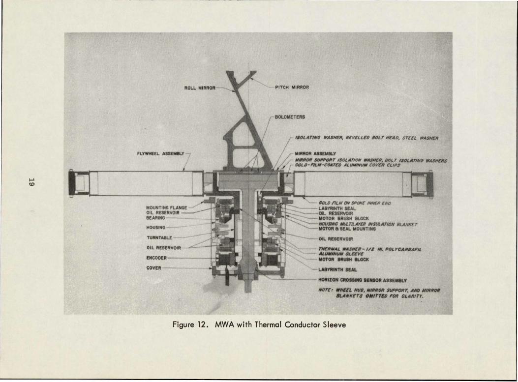
Further evaluation revealed that the 1VIWA was not isothermal Axial thermal gradients m the order of 8°C appeared undesirable because in some cases motor 1 brushes were not wearing while motor 2 brushes were, and vice versa. These gradients resulted from the use of titamum material for the shaft and housing (Figure 12). The thermal conductivity of titanium is about 14 times lower than that of aluminum. To create an isothermal condition between the two motors, an aluminum sleeve was designed and inserted as shown in Figure 12. When the possibility of using some other brash material was investigated, carbongraphite appeared to be a good choice because it should work well even with too much or too little lubrication These findings led to the following course of action
" A static test to obtain the MWA thermal profile inside and outside
o A test in thermal vacuum of an MWA with the aluminum sleeve insert
" Establishment of an analytical model for predicting thermal conditions by computer
* A test with carbon-graphite brushes
" Investigation of the possibility of using an OSO type lubrication system
" A theoretical lubrication-system analysis (ref. 6)
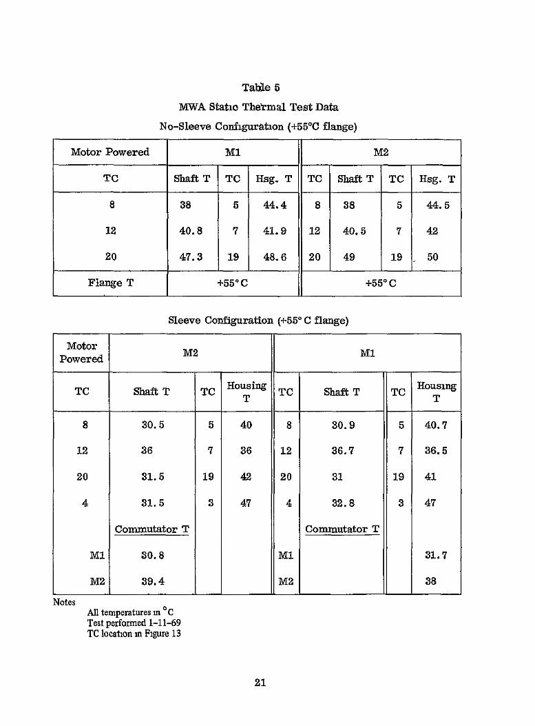
The MWA static test, performed in thermal vacuum with the aluminum sleeve in place and thermocouples placed as shown in Figure 13, resulted in a detailed thermal profile. Table 5 lists static test data from the sleeve and no-sleeve configurations for the +55CC MWA flange case. The temperature gradients without the sleeve were large in the radial direction at the motor 1 level (TC-8), and addition of the sleeve did not improve the condition. Temperature gradients between motors 1 and 2 (TC-8 and TC-20, respectively) were much less with the sleeve modification; however, temperature gradients increased along the outside housing. The sleeve modification made the IVIWA shaft more isothermal than before, which was desirable.
During these tests, an aluminum sleeve was installed on another MWA and operated in thermal vacuum. Table 6 lists the resultant data. Brush wear was still high for the short periods of operating time shown. With the sleeve, brush wear for motor 1 was somewhat reduced; without it, brush wear was greater (Table 6).
18
-VV
Alu
Figur 12PWAwthTeraMCnuco Sev
0 06
283
4 1 0462223 0
M2" M1' TOP VIEW BOTTOM VIEW
CONTROL PLATEN 43.44MOUNTING PLATE 46.46 S$ROUD 47.48
Figure 13. MWA Static Thermal Map, Thermocouple Locations
Table 5
MWA Static Thetmal Test Data
No-Sleeve Configuration (+550C flange)
Motor Powered M1 M2
TC Shaft T TC Hsg. T TC Shaft T TC Hsg. T
8 38 5 44.4 8 38 5 44.5
12 40.8 7 41.9 12 40.5 7 42
20 47.3 19 48.6 20 49 19 50
Flange T +55 ° C 1+550 C
Sleeve Configuration (+550 C flange)
Motor Powered
TC Shaft T TC Housing TC Shaft T TC Housing
T T
8 30.5 5 40 8 30.9 5 40.7
12 36 7 36 12 36.7 7 36.5
20 31.5 19 42 20 31 19 41
4 31.5 3 47 4 32.8 3 47
Commutator T Commutator T
MI 30.8 MI 31.7
M2 39.4 M2 38
Notes All temperatures miC Test performed 1-11-69 TC location m Figure 13
21
Table 6
MWA Development Test Results (50/50 silver graphite brushes)
Time on Shroud Mounting- Time (mls) Motor
Test Conditions Temperature Flange (mls (hr) Temperature @r)
Ml M2 M1 M2
Without thermal Not 37 to 570C 86 12 5 0 40 46 sleeve applicable
With thermal -110C 460 C 81 8.5 4 54 27 sleeve
30C 460C 6 6.5 0 6 0
50C 460C 6 3 0 3 0
250 C 460C 22 7.5 3 11 11
The MWA analytical model was set up using the previous static test data. Figure 14 shows the case for a sleeveless MWA with a +550 C flange; the temperatures shown are the differences between the static test and the computer model. The delta temperatures are no greater or less than 1. 5 C, indicating reasonable correlation.
As part of the ITOS program requirements, a full-scale thermal test model (TTM) of the ITOS spacecraft was constructed for use in developing and demonstrating the adequacy of the spacecraft thermal design The MWA was one of the few "live" subsystems on the TTM (most other subsystems were simulated by heaters). The number of thermocouples in the MWA area, although limited, was sufficient to permit comparison with the MWA analytical model. Figures 15 and 16 show this comparison for the hottest and coldest spacecraft thermal conditions, respectively.
The numbers circled represent the temperatures from the TTM tests. The data are within 20C where comparable (there are no comparative temperatures for everypoint), which indicated that the MWA analytical model might be useful for predicting MWA temperature distributions under other conditions. The analytical model was therefore developed further and its merit was demonstrated as shown in Figures 17 and 18, which are comruter runs without and with an
22
BOLOMETER HEAD
-7
fm;
'HUB
LABYRINTH
MOUNTING FLANGE
MOUNTING PLATE
x BRUSH BLOCK M1
-~ ----- U-IN
+0
BUSHTLOCM2
ROTOR M S
1 +15 NLAYINTH
-
ENCODER
/,ENCODER-HOUSING
(RTATING)
(STATINAR)END PLATE
~MI +1+2
--'
X DENOTES MODE TEMP CONTROLLED IN MODEL
ALL VALUES ARE ANALYTICAL CALCULATIONS N SLEEVE
POWERED
Figure 14. Correkiton of Analytical Mode! with Test Data (inside MWA housing)
Figure 17. Computer Prediction of Flight Temperatures (+550C flange without thermal sleeve)
26
BOLOMETER HEAD
31 °, FLYWHEEL T
386. 406- HUB
LABYRINTH
MOUNTING FLANGE 47 8'MOUNTING PLATE
371o NYLASINT
33 BRUSH BLOCK M1 37231STATOR M1
ROTOR MI
3BEARING
6SHAFT
SLEEVE
HOUSING
2 419' -NYLASINT
3950 ROTOR M2---- STATOR M2
BRUSH BLOCK M2 9
NYLASINT
S334LABYRINTH
BOLOMETER STEM
ENCODER (ROTATING)
36 ENCODER (STATIONARY)
HOUSING END PLATE
PWR MI - 127 W PWR M2 053W WITH SLEEVE
465 o
MIRROR SUPPORT -4 DEGREES
5020 MIRROR -77 DEGREES
SURROUNDS 64 DEGREES
Figure 18. Computer Prediction of Flight Temperatures (+550C flange with thermal sleeve)
27
aluminum sleeve respectively. Figure 19 summarizes these data and shows in more detail the significant decrease in temperature gradient between motors when the sleeve is used.
ROTOR BRUSHBLOCKROTOR BRUSHBLOCK
T M l
SHAF
3230SHAFT
(HOUSING 4280) (HOUSING 43 10)
(HOUSING 42 50) (HOUSING, 46 90)
3490
SLEEVE SEV 3832M
MROTO BRUS BL H RROTOR BLOCKOCK BH
4T5OTO 3330RL15..JT4Og M2
TEMPERATURES IN "C
NO SLEEVE SLEEVE
AT ALONG SHAFT 183 18
AT ROTOR TO ROTOR 151 12
AT BRUSH BLOCK TO BRUSH BLOCK 91 06 JAT HOUSING AT M1 LEVEL TO M1 ROTOR 153 100
AT HOUSING AT M2 LEVEL TO M2 ROTOR 11 76
55 DEGREE FLANGE Ml POWERED WITH 1 27W
Figure 19. Diagram Showing Effect of Adding Shaft Sleeve to MWA, +55°C Flange (1.27W to Ml winding, 0.53W to M2 winding)
As part of the previous procedural outline, two MWA tests were performed using carbon graphite (Stackpole M44A) brushes. MWA SN01PP was configured with these carbon graphite brushes. Carbon graphite brushes were installed in motor 1 of SN02P; the 50/50 silver graphite brushes were kept in motor 2 for expediency Figures 20 and 21 are graphs showing the rate of brush wear versus time and temperature data. The SN02P motor I carbon-graphite brush wear increased rapidly about hour 225 in Figure 20. Disassembly of the umt revealed strong indications of a thermal short across the thermal washer (Figure 12) An
28
x 4M1 M2 M I
2 - -
La
0
7
-w-
ILL
0. +250 045 -t
-101
0
1
32
-
64 g6 128 160 192 224 26
Figure 20.
NOTE •MWA had nclto fatemlsrtat end of test •Mot., 2 had 60/60 sliver graphite brushesI I I I
SN02P Motor 1 We*r-Temperature Data with Stackpole M44A Carbon Graphite Brushes
2
x
z
< CO. M2-M i
Q
M +25
0 32 64 96 128 160 192 224
I-
TIME (HOUR)
Figure 21. SN01PP Motor 1 Wear-Temperature Data with Stackpole M44A Carbon Graphite Brushes
increase in the conductor-coupling factor that would produce a thermal short was programmed into the computer, and the results appeared conducive to a thermal short. A characteristic that had not appeared before is that the carbongraphite brushes wore at different rates with respect to each other i.e., silvergraphite brushes on the same motor would wear within 5 rils of each other, whereas the carbon graphite brushes varied as much as twice that amount. Figure 21 is a plot of brush-wear data from SNO1PP which also had carbon-graphite brushes installed. Use of this brush material for this short period of operating time seemed promising. As the test continued, however, the carbon-graphite brushes showed signs of excessive wear and the test was terminated. Examination revealed that the eight brushes (four per motor) wore unequally It was concluded that carbon-graphite brushes were unsatisfactory for this application. Both of these tests used dioctyl adipate as the MWA lubricant A significant amount of brush noise monitored during the foregoing tests was an indication of overfilnnng, as before. Brush wear due to overfilming or too much oil can be related to electrical arcing; whereas, too little oil is related to mechanical or frictional wear.
A continuation of computer runs indicated that large radial temperature gradients still remained in the MWA To improve tins condition, many experimental changes in coupling factors were introduced into the computer program. The slant lettering in Figure 12 shows the resulting improvements on the MWA design As a result of re-evaluating test philosophy on the basis of the limitations of this brush motor, a review of orbital limitations, and investigation of other similar space applications (e g. , OSO Program), it was decided to modify the temperature test himts from +550 C and -100 C to +35* C and 0° C.
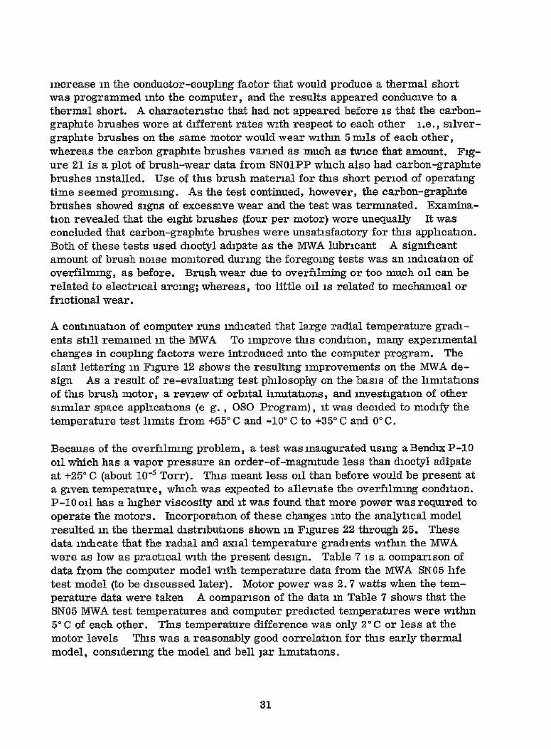
Because of the overfilning problem, a test was inaugurated using a Bendix P-10 oil which has a vapor pressure an order-of-magmtude less than dioctyl adipate at +250 C (about 10 -5 Torr). This meant less oil than before would be present at a given temperature, which was expected to alleviate the overfilming condition. P-10 oil has a higher viscosity and it was found that more power was required to operate the motors. Incorporation of these changes into the analytical model resulted in the thermal distributions shown in Figures 22 through 25. These data indicate that the radial and axial temperature gradients within the MWA were as low as practical with the present design. Table 7 is a comparison of data from the computer model with temperature data from the MWA SN05 life test model (to be discussed later). Motor power was 2.7 watts when the temperature data were taken A comparison of the data in Table 7 shows that the SNO5 M-WA test temperatures and computer predicted temperatures were within 50 C of each other. Tins temperature difference was only 20 C or less at the motor levels This was a reasonably good correlation for tins early thermal model, considering the model and bell jar limitations.
31
@ 132
250 M
2 3 MIRRORS -31. O C
r 217 0 0 22.4MIR R 3.O
180 199 . .
238 22.5
3 2182Z4*208@ NOTES
* CIRCLED NUMBERS ARE NODES IN ANALYTICAL MODEL
I ALL THERMAL FIXES
* Ml POWERED AT 27W
ALL TEMPERATURES IN DEGREES C
Figure 22. MWA Thermal Profile (+250C flange, M1 powered)
32
198
@ 134
@ -92
22-86
4-20 238
SPACECRAFT SURROUNDS 31.0°C
-- MIRROR SUPPORT -28.6 0 C
_ MIRRORS -31.1 0 C
2&0
* P
26 7 23.3 23 5
21 3205250 2239 -- " CIRCLED NUMBERS ARE NODES IN
233251 3 206 ANALYTICAL MODEL
" ALL THERMAL FIXES
216 * M2 POWERED AT 27 w
" ALL TEMPERATURES IN DEGREES C
Figure 23. MWA Thermal Profile (+25°C flange, M2 powered)
33
13 6
0 '
SPACECRAFT SURROUNDS + 5c
MIRROR SUPPORT -40 VC
17 MIRRORS -4265C
12 1
-1-1
l 908
-08
0-Z4
F NOTES
• T~l& CIRCLED NUMBERS ARE ODES N 0912 ANALYTICAL MODEL
03 ALL THERMAL FIXES-10 0
0 M1 POWERED AT 2 7W
•0 ALL TEMPERATURES IN DEGREES C
{ -13
Figure 24. MWA Thermal Profile (00(C flnge, M1 powered)
34
01 1
MU I
4-4212 3
SSPACECRAFT SURROUNDS + 5C
11 -- MIRROR SUPPORT -4a6°C
l]8MIRROS -42 oc
F2 41 Tem 1 9
NOTES INCIRCLED NUMBERS ARE NODES
ANALYTICAL MODEL ' r J 2.1 19
-05 •M2 POWERED AT 27W 0ALL TEMPERATURES IN DEGREES C
M2 powered)Figure 25. MWA Thermal Profile (0°C flange,
35
Table 7
Modified MWA Thermal Design (comparison of SN05 with computer model)
*SNOS is a life-test unit **Tis data isfrom the early MWA thermal analytical model of about 45 modes
The random nature of molecular motion causes a lubricant to migrate toward the coolest available surface where condensation can take place. In Figures 22 through 24 all commutator surfaces were cooler than or equal to the absolute temperature of the end reservoirs; in Figure 25 the commutator surface temperature tended to be equal to or greater than end reservoir surfaces. These temperatures carried a k3°C tolerance, so trend prediction could not satisfactorily be based on small temperature differences.
For a backup system, in addition to the design and development of a brushless motor, a brush motor using a lubricating system similar to that on the successful 050 satellite was being pursued. Sufficient brushes, nylasint reservoirs, and synthane ball retainers (for the bearing) were to be sent to Ball Brothers Research Corporation (BBRC)7 for their special lubricant-treatment process. These would then be assembled in the standard MTWA configuration, tested, and installed on a fhght spacecraft Because of the tight flight schedule, this approach was dropped later in 1969.'
Analysis of the investigations and testing to this point produced these conclusions:
* Life tests of three MVWA's shouldbe performedusing P-10 oil, 50/50 silver carbon brushes, thermal modifications shown in italics in Figure 12, and test range between +3500 and 0°C. Two units would initially have no end reservoirs. The third unit would be the complete flight configuration.
" Design and development of brushless motor backup would continue.
Life Tests
The primary objective of the life tests was to demonstrate the ability of the MWA to operate satisfactorily, for a minimum of 6 months, under nominal orbital conditions. Three life-test units were set up in bell jars in the fight configuration with the following initial exception. The SN05 configuration was like that in Figure 12. The SNOiPP and SN0ZP configurations were like that in Figure 12, except that no oil reservoirs were initially installed at motors 1 or 2. The MWA's were to operate for 6 months or until launch. Figure 26 shows the planned testing levels and durations of the life-test units.
Because the motor brushes appearedto be the least reliable item, brush-wear measurements were required about every 4 hours for detailed coverage. A strainguage monitoring device mounted on one brush of each motor measured the wear. Temperature data were recorded throughout the tests. The brushes consisted of 50/50 d:10 percent silver-graphite impregnated with Bendix P-10 oil, as were the nylasuit reservoirs. Usable brush height was 0.050 inches, width 0. 125 inches, and length 0. 062 inches. Nominal beginning-of-life (BOL) brush pressure was 16 to 19 psi and end-of-life (EOL) 4 to 7 psi
37
do
35C
2 o5 -
.0CL
S
35-C- - ,: N
2 5"C
•
2
w • 35°o, ,
-,M2
I
M2
M2
°
I
-
;/
SNO5
, ,
4 SNO1PP
__• _
P-10 LUBRICANT I I I SO/SO SILVER GRAPHITE BRUSHES TRANSITION RATE S30 C/HR
Ml BRUSHES IMPREGNATED WITH P-10 M1 IM2
MM1 M2 I
15 0C-IM
M1 M2-- _1M, F
_
2
4-18-69
M,
Ml M2 15 oC M2 M1
- 0 C I M2 I M1 F
SN02P
JN N- - (N u ] >
0- D
Figure 26. Profile for MWA Thermal-Vacuum Life Tests
Figures 27 through 29 are final thermal profiles and motor brush-wear data from the life test of MWA SNO5, SNO1PP, and SN02P. SN05 operated without interruption for 4250 hours; operation of SN01PP and SN02P was interrupted to add oil reservoirs to motors I and 2 (Figures 28 and 29); and SN02P was exposed to some special testing. Table 8 shows brush-wear data from these life-test units.
Table 8
MWA Brush Wear Results From Life Tests
MWA Operating Time (hr)
Brush Wear
(mils)
M1 M2
Operating
Temperature Range (degrees C)
SN05 2350 to 4250 3 6 2.7 +10 to +25
SN01PP 1550 to 3550 14 30 +10 to +25
SN02P 1200 to 1800 23 43 +10 to +25
In normal mission mode, MWA temperature was expected to be about +21C. Table 8 shows that the least brush wear was obtained for the temperature range of +100 C to +2500, which included the expected MWA operating temperature in space. The data in Table 8 emphasize satisfactory motor operation for the expected temperature range. Table 8 and Figures 27 through 29 show that, with time and no abnormal MWA changes, brush-wear rates decreased to acceptable values. At 000 m all three life-test umts, MWA operation could be tolerated for very short periods of time with low brush wear; this covered the acquisition phase of launch during which temperatures were expected to be near +70 C at the bearing.
Transients had an abnormal effect on brush wear; rate-of--change was 3° C per hour (Figures 27 through 29). The effect seemed greater for transients of the warm to cold type. In all cases, brush-wear rate decreased with time when the MWA was again operated in the +10C to +250 C range. Given a reasonable length of time at a stable temperature, especially in thd +100 C to +250C range, liimted motor switching did not seem detrimental to motor operation. It was shownthat time had a good effect on establishing a beneficial lubrication condition (Figure 29). A high period of wear occurred in the first 200 to 300 hours of operation (Figures 27 through 29), and this wear was positively established as brush
39
:zz gziz Z TI-SAIN GAUGE GAL WI 53 I so",07 , IL
, -2 TOf 2 --
iii imli4Ii[ OPERlATINGTIME (HOURfS)
NORl
(See R Peek MWA Ti lt Test Summary RCA2178 May 26, 1970)
Figure 27. MWA Thermal-Vacuum Life Test, SN05
12g0
STRAIN GAUGE CAL EDM, 1-70MILI 83,dM L
- - - - - - - - 2MOTOR 2
2 0I -- I -
i00
I I OPERATING TOME IHOURS)
,..-NO ENDRCBW$0$0 U G2RESER.O. 1.1MANDM2IREMOI.1
0 O MM M,M I Fl M2I
Figure 28. MWA Thermal-Vacuum Life Test, SN01PP
AM
-
f
-
MM . I
-I
-
I -M
000
W2 c cI
30 I0I 102Of0I
-i---------------------i
-
rc- -
Figure 29. MWA Th 'ermal-Valcuum Life Tes',SN 02P
wear-in or brush contouring. This occurred no matter what the operating temperature, but the brushes recovered in all cases. In all three cases, from 00 to +350C, the motor I brush-wear rate was generally lowest. Figure 29 shows the only case where motor 2 exhibited a lower rate of brush wear. At approximately hour 1800, the motor 2 brush-wear rate became lower than that of motor 1 when motor 2 was powered. Figures 27 and 28, and most other data indicate that this is not the usual condition: motor 2 generally wears more when powered than when unpowered.
SN02P (Figure 29) shows how changing the MWA internal temperature affected brush wear. Theaddition of a heater appeared to interchange the wear rates between motors I and 2; i.e., motor 1 brush-wear rate increased over that of motor 2. As the heat input was increased, brush wear rates increased; however, this could have resulted from the temperature change before hour 1800. After this test the heater was removed, and the MWA thermal blanket was removed tp study its effect. This reduced the wear rate of motor 2 but had no effect on motor 1. MWA SN02 was then restored to its normal configuration (no heaters and blanket installed), and both motors returned to the lower (more desirable) wear rates.
The data in Table 8 and the life-test units demonstrated that, when the MWA motors were let alone (no heaters, operation at +100C to +300C and normal configuration), brush-wear rates were low and greater-than-mission life could be predicted.
MWA Flight Unit SNO6 (TIROS-M/ITOS-1) Acceptance Tests
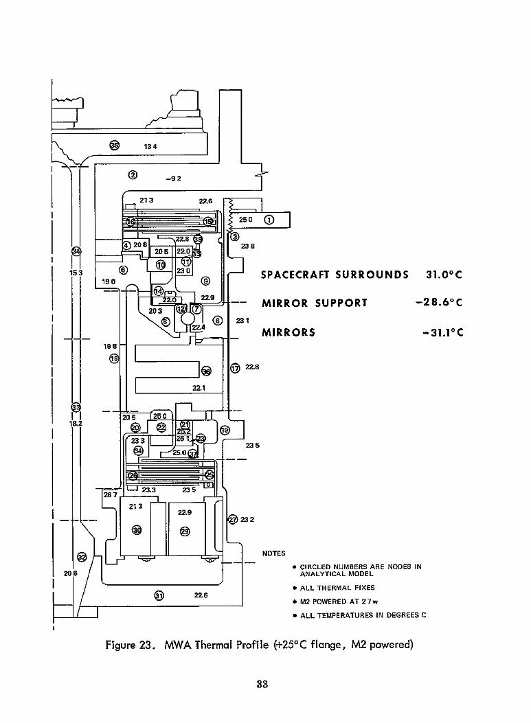
MWA SN06 (configured as shown in Figure 21) was exposed to normal subsystem testing and subsequently installed on TIROS-M, the first fight spacecraft of the ITOS series. TIROS-M was then subjected to the thermal-vacuum profile of Figure 30 (top curve) starting at approximately hour 180. The lower set of curves in Figure 30 illustrate the MWA brush-wear profiles for motors 1 and 2. At hour 265, motor 2 showed a sharp rate of increase in brush wear: the brushes had worn 8mils in 24 hours. This degree of wear had not occurred in any subsystem or life testing since the MWA was modified to the Figure 21 configuration. Review of the MWA life-test performance (Figures 27, 28, and 29) and comparison of MWA thermal-model data with the TIROS-M thermal-vacuum test profile (Figure 30, hours 180 to 290) led to the conclusion that the TIROS-M thermal-vacuum test embodied conditions of overtest unlike those experienced in the life tests or those that should exist in orbit.
43
MWA MWA
u 40-EM
FLANGE t4 BASEPLATE TEMP (T IREMPM M))TFRA
FLANGE TEMP
-20
20
BSYSTEM MWA ) S/C ALL UP
TEST _ _ _ _ _ _ _ __E
S/C SOAK TEST OFF TV TEST (SN06) MOTORS SWITCHED
EVERY 6 HOURS MAGNETIC DIPOLE TEST IN AIR
1-HR DETAILED SUBSYSTEMS 2-HOUR ELECTRICAL INITIAL ELECTRICAL TEST IN AIR SYSTEMS TEST IN AIR
Figure 30. MWA SN06 Test Profile and Brush Wear Data
Conditions in the area of overtesting during the TfROS-M thermal-vacuum acceptance test were
" High temperature and high positive-temperature gradient from oil reservoir to motor could cause overfilming which would lead to arcing orelectrical brush wear at the +400C level in Figure 30.
* Low-temperature and negative-temperature gradients from oil reservoir to motor constitute a marginal lubrication condition which could lead to frictional or mechanical wear (00C and +50C operation in Figure 30).
* Operation during rapid temperature transients unbalances the vaporlubrication system; this could cause more brush wear than expected and dould require a long stabilization time for lubrication conditions which are conducive to reduced brush wear (Figure 30).
" Frequent switching between motors 1 and 2 changed thermal distribution in the MWA (shown by analytical model) and caused transient brush-wear conditions (motors switched every 6 hours in Figure 30).
None of the foregoing conditions were expected to occur in orbit, because the orbital temperature range of the MWA was predicted to be between +15' C and +270C, and the life testing demonstrated satisfactory MWA operation in the temperature range +100C to +250C (Table 8). The worst orbital temperature transient was expected to be very low, a change of 0. 5° C at the rate of 0.6°C per hour. No requirement was necessary for frequent motor switching. These facts indicated that the design was acceptable and added to NASA's confidence that the TIROS-M MWA SNO6 was flightworthy. Additional justification for flying MWA SN06 was the brush-wear curves after the occurrence of the anomaly (Figure 30): as the temperature was raised +10°C and above, motor 2 brushwear rate decreased rapidly. At approximately hour 560, more MWA operation time was added to the test to further demonstrate that the accelerated wear condition had been terminated. At hour 665, the test was stopped and the life expectancies for motors I and 2 were computed as 1. 5 years and 0.75 year, respectively. The spacecraft mission life is 6 months with a design goal of I year Based on the life tests, brush-wear rates decreased with time at constanttemperature operation. Therefore, the MWA SNO6 was expected to perform longer than the mission requirements.
MWA SN06 Performance in Orbit
On January 23, 1970, TIROS-M was launched and redesignated ITOS-i. During the early days in orbit, overall operation in the checkout phase met expectations. Motor 1, first of the two redundant motors to be operated, checked out
45
satisfactorily (the motors required 1. 98 watts in space versus 2.7 watts in system testing). On orbit 66, motor 2 was selected. This motor showed a wear rate slightly greater than that of motor 1, which was consistent with test experience, and therefore expected. In order to avoid unnecessary switching of the motors, which was expected to cause brush wear, checkout of motor 2 was continued. As a precautionary measure, continuous operation of selected spacecraft subsystems was initiated to raise the temperature of the satellite baseplate and hence the IVMWA motors (Figue 31), in an attempt to provide a better lubrication envraonment.
During orbits 199 to 204, motor 2 brush wear increased rapidly, and motor 2 was switched off in favor of motor 1. At this time, to provide additional heat to the MWA, the satellite was operated as closely as possible to normal mission mode on a noninterference basis with the operational spacecraft ESSA 9. This improved the thermal environment. A significant reduction in motor 2 brushwear rate was noted by orbit 260 from 6 to 1.5 mils per day (Figure 31). The baseplate temperature stabilized at approxmately +250 C. The bearing temperature continued to rise until it stabilized between +30'C and +35°C. This high MWA temperature was caused by the additional power requirement to drive motor 1, a direct result of the motor 2 brush materal causing an electrical short 8. Although motor 2 was unpowered, its brush wear continued at a low rate until its indicated end-of-life on orbit 904.
MODIFICATION TO ENSURE MOTOR REDUNDANCY
ITOS-1 MWA SN06 Motor 2 Failure Analysis
On the basis of previous test history it was concluded that the possible causes for the failure of motor 2 were marginal lubrication, defective materials, and defective workmanship. However, a review of the manufacturing and testing history of the MWA gave no indication that the last two causes were directly responsible for the anomaly. The conclusion was that lubrication conditions from motor 2 in orbit must be more marginal than was demonstrated by system testing.
The MWA SNO6 motor 2 brush failure was analyzed in detail. An extensive renew and additional tests of the MWA were conducted to verify the exsting MWA computer thermal model, validate previous MWA life testing, renew the acceptance-test history where SN06 motor 2 exhibited high brush wear, and select a method to prevent recurrence of the brush-wear anomaly The early 1969 computer model produced good correlations between temperature predictions and measured values in a bell-jar test, using only the MWA with a motor power of 2.7 watts (Table 7).
In the spring of 1970, an elaborate series of tests were performed to carry out the functions outlined above The first series of tests conducted in a thermal vacuum environment were static and used MWA SNO1PP, a representative spacecraft baseplate and adapter ring (Figure 32). It was equipped with a flight-type inertia wheel, mirror, and blanket assemblies. All heat inputs were simulated as closely as possible to the MWA on ITOS-1 Because a higher MWA thermal environment was thought to improve the lubrication of motor 2, heaters were added to the MWA at the flange and encoder levels. The rotors were locked and the thermocouples were mounted inside and outside at nearly every node corresponding to the computer model (Figure 33).
The tests performed included variable satellite baseplate temperatures, such as mission mode (+170C) and acquisition mode (+110 C), variable motor powers of 1. 98 watts (normal space power condition) and 7.18 watts (ITOS-1 MWA failed condition); and motor 1 or motor 2 operating conditions. Figures 34, 35, and 36 compare the computer predicted and static test temperatures for acquisition and 30- and 60-degree (sun-angle) begimng-of-life (BOL), respectively. The good correlation fouid along the outside housing did not appear internally; however, the temperatures were not more than 20C apart. Failure to achieve any closer temperature figures was attnbutedlto the test and computer setup limitations. Figure 37 shows the thermal profile of the IVIWA m approximately its failed thermal condition. Motor I is operating here in supposedly adverse thermal conditions, i e. , the commutator is +36, 4°C and the brush +310 C, which had previously been called a negative temperature gradient. The end reservoir is +31.90 C and the main reservoir is +33 ° C. This condition infers that temperature gradients are not as important at high lubrication temperatures, because the availability of oil is greater. References 9 and 10 discuss this test mgreater detail. In general, results of the static tests verified the preflight conclusion that motor 2 should have operated satisfactorily at +10°C (flight temperature at minimum spacecraft operation).
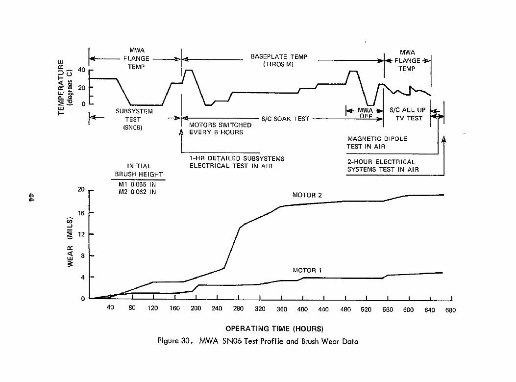
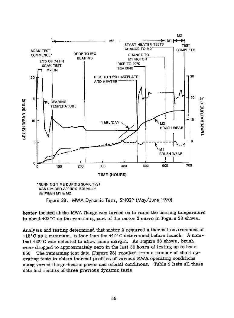
The second series of MWA tests conducted in thermal vacuum with the motors operating (dynamic tests) in a test setup similar to that in Figure 32, but with fewer thermocouples than the static tests, attempted to repeat the brush-wear anomaly and to acquire additional MWA thermal data under dynamic conditions. Based on the need for a flange heater deternned by preliminary analysis, a flange heater was mounted on the MVWA (baseplate MWA flange-mounting interface) for this test. The flange-heater effect is analogous to raising the baseplate temperature. Brush wear on motor 2 was induced in this test (hours 300 to 460 in Figure 38), but the wear rate was approximately an order of magmtude less than that expenenced by ITOS-1 m orbit. The motor 2 brush wear data (Figure 38)confirmedthis: thewear rate was 1 milper dayversus the 8mils per day previously exhibited in ground testing of TIROS-M. To repeat the corrective measures taken with ITOS-1, the baseplate temperature was raised and the
48
Figure 32. MWA SNOIPP Static Thermal Test Configuration
34~ -tt3-13 9
MII
NOTE
ONLY MAIN T/C. ARE SHOWN. SEE SEPARATE SKETCH SHEETS FOR ORIENTATION AND POSITION OF ALL DUPLICATE TIC's
36 (DETAILS IN REFERENCE 9
18
Figure 33. MWA SNO01PP Static Test Temperature Senor Locations
50
NOTES
a
*
*
ACQUISITION CASE
M2 POWERED
TOTAL POWER 198 WATTS
1 * ALL TEMPERATURES IN DEGREES C
COMPUTER STATIC PREDICTED TEST
39 SURROUNDS
40 MIRRORSUPPORT
(17 6)'C
-29 8
(176)00
-31 8
41 MIRRORS BASEPLATE
-31 6 -33 114
1
SINK TEMP (-100) (-102z9)
36
22 21
LOCATION (SEE
DIAGRAM)
"1
COMPUTER PREDICTED
"T"
(81)
73
STATIC TEST
T"
(81)
69
37 8
10
65
97
57
92
27 11
21
72
93
65
84
22
27
55
81
54
72
31 81 64
36
37
92
71
84
65
38 70 71
31
Figure 34. MWA SN01 PP Static Thermal Test - Acquisition Case
51
_ __NOTES
5
36
22 21
T---
V7
31
-30 DEGREE BOL CASE
* M2 POWERED
* TOTAL POWER 198 WATTS
* ALL TEMPERATURES IN DEGREES C
COMPUTER STATIC
PREDICTED TEST
39 SURROUNDS (284)0C (28 4) 0C
40 MIRROR SUPPORT -23 9 -229
41 MIRRORS -260 -244
BASEPLATE -26 7
SINK TEMP (-100) (-100 5) 1 1 1
LOCATION COMPUTER STATIC (SEE PREDICTED TEST
DIAGRAM) IT,'I,
1 (225) (225)
5 190 200
8 164 182
10 173 184
11 187 202
27 201 205
22 202 207
27 188 188
31 184 174
36 181 196
37 200 202
38 136 197
Figure 35. MWA SNOIPP Stalic Thermal Test, 30-Degree BOL Case
52
NOTES
o 60-DEGREE SOL CASE
* M2 POWERED
* TOTAL POWER 198 WATTS
* ALL TEMPERATURES IN DEGREES C
39 SURROUNDS
40 MIRROR SUPPORT
41 MIRRORS
BASEPLATE
SINK TEMP
COMPUTER STATIC PREDICTED TEST
(21 7) °C (21 7)C
-276 -27 9
-29 5 -294
155
(-100) (-1026)
LOCATION COMPUTER STATIC (SEE
DIAGRAM) PREDICTED
"T" TEST "T"
36 1 (126) (126)
5 114 117
8 94 104
10 105 107
22 11 113 116
21 133 135
22 138 144
27 121 123
31 120 114
36 11i 122
27 37 133 135
38 112 114
31
Figure 36. MWA SNO1PP Static Thermal Test, 60-Degree BOL Case
58
169
3 3O 3 SURRUND 314
2A94AT 2691 0 N so6MIRROR SUPPORT - 16 814.32MI8SRROUNS
!~ ~ 36 _ LJ 4a3T 31 2F (-) D
- ' 306 MIRRO SPPRATR - 6 8187AELT
BAEPAT 261
* NOMINAL POWtER ON MI
So TOTAL POWER 718 WATTS
@ ALL TEMPERATURES IN DEGREES C
* CIRCLED NUMBERS CORRESPOND TO~NODES IN COMPUTER MODEL
Figure 37. MWA SNOIPP Static Thermal Test, Simulation of ITO-1 Failure
54
M2
M2 1M14 O START HEATER TESTS TEST CHANGE TO M2- COMPLETE
COMMENCE* DROP TO SC CHANGE TO BEARING MI MOTOR
SOAK TEST
END OF 74 HR RISE TO 220CSOAK TEST BEARINGM2 ON
20 RISE TO 170C BASEPLATE 30 AND HEATER
2015 ClBEARING o.
tnTEMPERATURE
L 10 10
IL::AY BRUSH WEAR
I I~~0
Iw
- - BRUSH WEAR
1 _ I _ I
100 200 300 400 500 600 700 0
0
TIME (HOURS)
*RUNNING TIME DURING SOAK TEST WAS DIVIDED APPROX EQUALLY BETWEEN M1 & M2
Figure 38. MWA Dynamic Tests, SN02P (May/June 1970)
heater located at the MWA flange was turned on to raise the bearing temperature to about +220C as the remaining part of the motor 2 curve in Figure 38 shows.
Analysis and testing determined that motor 2 required a thermal environment of +15'C as a nummum, rather than the +100C determined before launch. A nominal +220 C was selected to allow some margin. As Figure 38 shows, brush wear dropped to approximately zero in the last 30 hours of testing up to hour 650 The remaimng test data (Figure 38) resulted from a number of short operating tests to obtain thermal profiles of various MWA operating conditions using varied flange-heater power and orbital conditions. Table 9 lists all these data and results of three previous dynamc tests
55
Table 9
IVIWA SN02P Dynamic Tests, Flange Heater Test Results
Variable
Mean baseplate temperature °C
'Surrounds' temperature °C
Flange heater power w
M2 motor power w
rpm
Flange (node 1) 0C
Housing at heater (3) M 0 C
Housing at bearing (5) 0 0
Housing at reservoir (17) 0C
Housing at M2 (19) 0C
Housing at encoder (27) 0 C
End cap (node 31) °C
AT, bearing - baseplate °C
AT, housing at M1 (bearing) level, housing at M2 level
Motor powered
Baseylate*Mission Mode +17 C
**Standby Mode k+5 0 C
1
17.8*
23.3
5.0
2.85
-
17.0
26.7
25.2
25.4
25.0
21.6
19 0
7 4
0.2
M2
2
17.3
22 1
1.80
2 75
-- 150
15 7
20.0
20.0
19 8
20 0
18.0
16.2
2.7
0
M2
3
16.9
22.0
2.75
2.65
15.7
23.0
22.1
22.2
22.0
19.3
17.1
5.2
0.1
M2
Temperatures
4 5 6 7 8
5** 5 6 10 16.5
5.8 5.8 6.5 14.5 22
5 0 7 0 8.2 5.0 3.0
1 96 1.75 1.80 2.0 2.0
- - 85 to 105 rpm
7 8 9.5 11 16
19 24 5 28.5 22 5 22
15.5 19 22 19.5 20
15.7 20 23 19.6 20
15 18.8 21 19 20
11 13 15 15.5 17.5
8 10 11.5 13 16
10.5 14 16 9 5 3.5
0 5 0.2 1 0 0.5 0
M2 M2 M2 M2 M2
Data in columns 6 and 8 indicate the amount of flange heater power required for standby and mission modes, respectively The standby mode was the result of testing performed by GSFC during the engineering evaluation and it was recognized that heaters were required for in-orbit operation and storage of the satellite. (References 10 and 11 discuss this phase of dynamic testing in greater detail.) This limited amount of flange heater testing demonstrated its feasibility: a higher operating temperature improved motor 2 lubrication and reduced brush wear.
Heater Modification
The analysis and testing and ITOS-1 experience in orbit indicated that the temperature of motor 2 should be a minmum of +150C. Therefore, a nominal MWA temperature of +230C :-30C was selected to ensure system operation. Because testing experience using the flange heater was limited, a second series of dynamic tests was conducted to further demonstrate the use of heaters for reducing motor 2 brush wear and ensuring motor redundancy. Table 10 summarizes these test results (see reference 12 for detail). A heater was mounted at the main reservoir, because the flange-mounted heater was not yet determined to be the final solution. Figure 39 shows this change. In Table 10, tests 1, 4, 5, 6, and 6a are comparable to standby cases, test 1 conditions being primary. The remaining tests were shorter to gather data on other MWA conditions. Table 11 and Figure 40 summarize these test results, which indicate that conditions in tests 5 and 6 were required for standby and those in tests 7 and 8 for mission mode.
As ITOS-A, the next flight spacecraft, was being prepared for launch, its thermal-vacuum acceptance-test results were used as the final confirmation for heater modification Table 12 shows the heater combinations and their expected use
The thermal-vacuum retest (Figure 41) demonstrated the use of heaters onITOS-A IMWA SN04, as further insurance that motor redundancy would be provded. In the prenous testing, the flange heater served to maintain a bearing temperature of +23°C -+3°C (TC-36 in Figure 42). The main reservoir heater was to be used if the temperature dropped below +200C, but it was not required Results of the temperature data moitored on MVWA SN04 during the ITOS-A retest (Figure 42) indicated that 31watts should be required for mission mode and 9 watts for standby mode; these figures are closer to the data from the SNOlPP static test than the dynamic test data in Tables 9 and 10. Several factors may govern the failure to achieve a better overall correlation of data
" Dissimilarity between MVWA umts
* Inequality of static and dynamic tests
* Inability to properly simulate the environment of a spacecraft which is completely configured and operating
57
Table 10
Second Series of Dynarmc Tests (5-2-70 through 6-3-70) (SN02P with heaters)
Test TetMain Baseplate Surrounds Flange Heater Reservoir Motor Powered Approximate
Duration Number Acronym (degrees 0) (degrees C) (watts) Heater days)
(watts) (days)
1 C-9FL-DA 5 5 9 - M2 at 2.7 watts* 5
2 FM-2' 17 23 5 - M at 2 watts** 1
3 FS-60' 15 5 21.7 - - M2 at 2 watts 1
4 C-9FL-DA? 5 5 9 - M2 at 2.7 watts 0.5 (Repeat of number 1 test)
5 C-9FL-SMR-D 5 5 9 3 M2 at 2 7 watts 10.5
6 C-9FL-3MR-D 5 5 9 3 M1 at 2 7 watts 2
6a C-9FL-3MR-D'2 5 5 9 3 M1 at 2 watts 0 5
7 W-6FL-D1 17 23 6 - M2 at 2 watts 2
8 W-6FL-D2 17 23 6 - M2 at 150 rpm 3
Total 25.5 days *Power required to operate at 150 rpm m gravity field
**Power required m orbit
FLANGE
N HEATERS 1 & 2
NN B1EARING
A MAIN RESERVOIR
4EATER 3
Figure 39. MWA Wheel, Cross-Sectional View (showing heaters)
59
Table 11
Summary of MWA SN02P Dynamic Heater Tests (September 1970)
Test 1 2 3 4 5 6a 6 7 8
Mean baseplate temperature (39, 110-115) 'C 5.22 18 55 15.37 5.70 7.10 4.76 6474 17.82 17.14
Surrounds temperature (129) C 5 57 23 38 22.00 5.57 7 76 4.57 6.26 22.54 23 29
Flange heater power w 9 5.0 - 9 0 8.97 9.0 9.0 6.05 6.09
Main res. heater power w - - - 3 01 3.0 3.0 - -
MI motor power w - 1.84 - - - 1.99 2.29 - -
M2 motor power w 2.49 - 2.17 2.43 2 26 - - 2.02 2 27
Housing at flange motor (3, 53, 54, 55) °C 18 13 21.95 11.95 18.20 25 36 23.99 24.63 24.99 25.55
Housing at bearing (5, 56, 57, 58) °C 15.96 20 31 12 06 16.07 23.31 22.55 23.17 21.47 22.38
Housing at main reservoir (17, 74, 75, 76) 9C 15.60 20 43 12.85 15.24 25.74 24.74 25.51 20.87 21.93
Housing at M2 (19, 78, 79, 80) °C 14.64 20.70 14.30 14.26 26.40 23 34 25.53 20.56 22 01
Housing at encoder (27, 91, 92, 93) 0 C 10 50 17.69 13.56 10.60 19.36 16.28 18.24 18.77 20.11
End cap(31, 99, 100, 101,102) °C 7,25 17.13 13.99 7.34 13.53 10.73 12.47 17.58 18.79
150 LEGEND
MIO STRAIN GUAGE CAL 561lv/m M2A STRAIN GUAGE CAL 85pv/mjl 8-24-70 to 9-11-70
100
01
> U 0 50
TEST 2 TEST 3-50
FH-2 FS-60
.TEST 1 TEST 5, 6 AND 6aC-9F-M C-9F-3MR
0 50 100 150 200 250 300 350 400 450 500
TIME (HOURS)
Figure 40. MWA SN02P Dynamics Test with Heaters
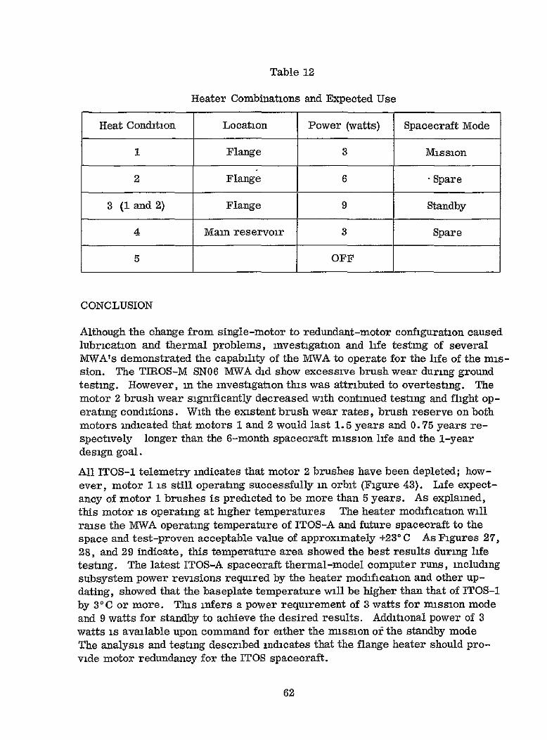
Table 12
Heater Combinations and Expected Use
Heat Condition Location Power (watts) Spacecraft Mode
1 Flange 3 Mission
2 Flange 6 - Spare
3 (1 and 2) Flange 9 Standby
4 Main reservoir 3 Spare
5 OFF
CONCLUSION
Although the change from single-motor to redundant-motor configuration caused lubrication and thermal problems, investigation and life testing of several MWA's demonstrated the capability of the MWA to operate for the life of the mission. The TIROS-M SN06 MWA did show excessive brush wear during ground testing. However, in the investigation this was attributed to overtesting. The motor 2 brush wear signficantly decreased with continued testing and flight operating conditions. With the existent brush wear rates, brush reserve on both motors indicated that motors 1 and 2 would last 1.5 years and 0.75 years respectively longer than the 6-month spacecraft mission life and the 1-year design goal.
All ITOS-1 telemetry indicates that motor 2 brushes have been depleted; however, motor 1 is still operating successfully in orbit (Figure 43}. Life expectancy of motor 1 brushes is predicted to be more than 5 years. As explained, this motor is operating at higher temperatures The heater modification will raise the MWA operating temperature of ITOS-A and future spacecraft to the space and test-proven acceptable value of approximately +230 C As Figures 27, 28, and 29 indicate, this temperature area showed the best results during life testing. The latest ITOS-A spacecraft thermal-model computer runs, including subsystem power revisions required by the heater modification and other updating, showed that the baseplate temperature will be higher than that of ITOS-1 by 3°C or more. This infers a power requirement of 3 watts for mission mode and 9 watts for standby to achieve the desired results. Additional power of 3 watts is available upon command for either the mission or the standby mode The analysis and testing described indicates that the flange heater should provide motor redundancy for the ITOS spacecraft.