TISDALE TWP. M-315 7 6 J 5M 4M l \ L .O. 328 H.R. 826 3 H .R. 907 \ \ I P 6 M 3 9 ! l 6 ! l 3 9 O l l l G88688 li J. 688677 H.F 361 P 6 8 8 664 P) s.** o R7I83 \ H.R. 868 H.S. 803 H. S. 611395 6 1/1 3 c 4 H.R. 1173 764406 \RY18O-A H.R. 990 \ -i*-\ l-ti. - .'l 5670 |5I2 l i f P. 4 J 7 580,13 '- H.R. 904 P 7426 \ R 9598 \\ R Y 180 \\ tPt.3) H.R. 886 x P. 7413 M.E. 67 \ tp P 9602 P. 8637 (P M.E.58 P. 9604 M.E.59 R 9603 H.R. 888 \ 555626 e H. R.903 P. 9599 H.R. 1083 H.S. 745 \P2I828 H.R.902 R 9600 R.S.C. 1 77,- Pi 26690 H.R.90I P 9601 P "K 566718 H.R.1081 \ T.R.P 568V l 6 \ \ P l (H.R.892! P 764401 P. P 78 ..' 759000 PP 79 190490 H.R, 828 \ H.R.1171 \641 R 8197 70095& R 8980 P. 16925 529006 i H.S.I038 J P /-58I36 P.f 3 7705 8127! p 75SI25 \ P. 8115 P. 21750 x H.R.860 H.R. 659 M P- P. 9853 \ l(P 753120 \ H.R 862 J H.R. 863 S P. 9 1/91 P. 9192 P.20279 P.26859 T.R R 2761 l P . II3II P 19975 P. 33658 ; P. 33660 P P. 22393 P. 22)395 \ \f)97!06 [P 597105 \ / " P. 20676X \ f Cook L. P /^7!07 P 59 P'597112 i P 597i;l i P 59/1 10 P. 22146 \'P. 2 2147 \ P.22148 \ P, 21279 P. 21280 P. 221531 i P' 1869 P. 22151 SRO i P. 21350 l . P \ 2I678\ l P- 21677 \ U P. 21326 V P. 24473651367 ADAMS TWP. M-261 (T- ff^ \ vJ ' ro o O: x C/) THE TOWNSHIP OF DELORO DISTRICT OF COCHRANE PORCUPINE MINING DIVISION SCALE' 1-INCH* 20 CHAINS EGEND PATENTED LAND CROWN LAND SALE LEASES LOCATED LAND LICENSE OF OCCUPATION MINING RIGHTS ONLY SURFACE RIGHTS ONLY ROADS IMPROVED ROADS KING'S HIGHWAYS RAILWAYS POWER LINES MARSH OR MUSKEG MINES CANCELLED PATENTED S R.O. (P) C.S Loc. L.O M.R.O S.R.O c. e NOTES 400' Surface Rights reservation along the shores of all lakes and rivers. For status of fraction situated between Mg. Claims H.R.II32i H.R.947 a M.E.42 see File No. 119653 Mming claims within the area shown thus ............,............ are subject to rights Q privileges granted under An Easement Order dated May !9,!937 to Delnite Mines Ltd. This township lies within the Municipality of CITY of TIMMINS. AREAS WITHDRAWN F ROM DISPOSITION M.R.O. -MINING RIGHTS ONLY S.R.O. - SURFACE RIGHTS ONLY M.+ S. - MINING AND SURFACE RIGHTS Description Order No. Oste Disposition PH* PLAN NO.- M-272 ONTARIO MINISTRY OF NATURAL RESOURCES SURVEYS 'AND MAPPING BRANCH 42A06NE8405 2.5739 D ELORO 200
Transcript
TISDALE TWP. M-3157 6
J
5M
4M
l \ L .O. 328H.R. 826 3 H .R. 907
\ \ I P 6 M 3 9 ! l 6 ! l 3 9 O ll lG88688 li J. 688677
H.F 361 P 6 8 8 664
P) s.** oR7I83 \ H.R. 868
H.S. 803 H. S. 611395 6 1/1 3 c 4
H.R. 1173
764406 \RY18O-A H.R. 990\ -i*-\ l-ti. - .'l
5670 |5I2
l i
f P. 4J 7 580,13 '-H.R. 904
P 7426 \ R 9598 \\ R Y 180
\\ tPt.3)
H.R. 886 x
P. 7413 M.E. 67 \ tp
P 9602P. 8637 (PM.E.58
P. 9604M.E.59
R 9603 H.R. 888 \ 555626
eH. R.903
P. 9599H.R. 1083 H.S. 745 \P2I828
H.R.902 R 9600 R.S.C. 1 77,-Pi 26690
H.R.90I P 9601
P"K 566718
H.R.1081 \ T.R.P568V l 6 \ \ P
l (H.R.892!
P 764401 P. P 78..' 759000
PP 79
190490
H.R, 828 \ H.R.1171 \641R 819770095&
R 8980
P. 16925
529006 i
H.S.I038 J P /-58I36P.f 3 7705
8127! p75SI25
\ P. 8115
P. 21750 xH.R.860 H.R. 659
M P- P. 9853 \
l(P 753120 \ H.R 862 J H.R. 863
S P. 9 1/91 P. 9192
P.20279
P.26859T.R R 2761 l P . II3II
P 19975 P. 33658 ; P. 33660
P
P. 22393 P. 22)395 \
\f)97!06 [P 597105 \ /"
P. 20676X
\ f Cook L.P /^7!07 P 59
P'597112 i P 597i;l i P 59/1 10
P. 22146 \'P. 2 2147
\ P.22148
\
P, 21279 P. 21280P. 221531 i P' 1869
P. 22151 SRO i
P. 21350 l. P \
2I678\ l P- 21677\ U P. 21326
VP. 24473651367
ADAMS TWP. M-261
(T-ff^ \ vJ '
ro
o
O:
xC/)
THE TOWNSHIP OF
DELORODISTRICT OF
COCHRANE
PORCUPINE MINING DIVISION
SCALE' 1-INCH* 20 CHAINS
EGEND
PATENTED LANDCROWN LAND SALELEASES
LOCATED LANDLICENSE OF OCCUPATION
MINING RIGHTS ONLY
SURFACE RIGHTS ONLY
ROADSIMPROVED ROADSKING'S HIGHWAYS
RAILWAYS
POWER LINESMARSH OR MUSKEGMINESCANCELLEDPATENTED S R.O.
(P) C.S
Loc.L.O
M.R.O
S.R.O
c.e
NOTES400' Surface Rights reservation along the shores of all lakes and rivers.
For status of fraction situated between Mg. Claims H.R.II32i H.R.947 a M.E.42 see File No. 119653
Mming claims within the area shown thus ............,............
are subject to rights Q privileges granted under An
Easement Order dated May !9,!937 to Delnite Mines
Ltd.
This township lies within the Municipality of CITY of TIMMINS.
AREAS WITHDRAWN F ROM DISPOSITION
M.R.O. -MINING RIGHTS ONLY
S.R.O. - SURFACE RIGHTS ONLY
M.+ S. - MINING AND SURFACE RIGHTS
Description Order No. Oste Disposition PH*
PLAN NO.- M-272ONTARIO
MINISTRY OF NATURAL RESOURCESSURVEYS 'AND MAPPING BRANCH
\ LEGENDPATENTEDCROWN LAND SAi.^LEASESLOCWED LANDLICENSE, OFMINING R IGHTS d*ILYSURFACE RIGHTS - W S R'
IMPROVED ROADS KIN6'^ HIGHWAYS ^ RAILWAYS'
•POWER L INES f MARSH OR MUSKEG MINES '-" -f : ' CANCELLEDPATENTED S.R.O.REGISTERED "KAN; OF
*l
NOTES400 Surface Rights reservation of all lakes and river's.
the
For *takjs of fraction s it.uated t^twt*n Mf. Claimj J H.R.947 B M.E.42 Me FrttN*Mf965
Mining claims within ttie qrfo tjibwh thus ^......™Jore subject to rights 8 prnnltfge* granted und Eostment Order dated May 19,1^7 .to Delnito Mi] lltd.
This townihfp li*i w ithin the of CITY of nUijHNS.
pplttUTf r ̂ '
v
"*" i-^nCUriNE MINING DIVISIOND) E y E
f *
fONTARIO
MINISTRY OF NAtURAL RESOURCESSURVEYS AND MAPPING BRANCH210
PATENTED LANDCROWN LAND SALELEASESLOCATED LANDLICENSE OF OCCUPATIONMINING RIGHTS ONLYSURFACE RIGHTS ONLYROADSIMPROVED ROADSKING'S HIGHWAYS
RAILWAYSPOWER LINES
MARSH OR MUSKEGMINESCANCELLED
C.S.
Lac.LO.
M.R.O. S.R.O.
NOTES
400' Surface Rights Reservation along the shores of all lakes and rivers.
This township lies within the Municipality of CITY of TIMMINS.
Areas withdrawn from staking under Section
3 of the Mining Act . R SO !97C ' lo. File Date Disposition
W.25/77 I68543 n/3/77 S.R.O.
PLAN NO. M. 261ONTARIO
MINISTRY OF NATURAL R ESOURCESSURVEYS AND MAPPfNG BRANCH
42A06NE8405 S.5739 DELORO 220
10
GA
MM
A C
ON
TOU
R L
INE
50
GA
MM
A C
ON
TOU
R L
INE
250
GA
MM
A C
ON
TOU
R L
INE
(1 G
AM
MA
zr
1 N
AN
OT
ES
LA I
N S
I U
NIT
S)
MA
GN
ETI
C D
EP
RE
SS
ION
81 0
20'
48
0 2
5'-
TIM
MIN
S
42A
81 9
10' 48
*2
5'
500
1000
MS
cale
1:
1500
0
TOTA
L M
AG
NE
TIC
IN
TEN
SIT
Y S
UR
VE
Y
CO
MS
TA
TE
R
ES
OU
RC
ES
LT
D.
DE
LOR
O/A
DA
MS
TO
WN
SH
IPS
Pro
vince
o
f O
NT
AR
IO
FIL
E N
O.
25
01
1
SH
EE
T N
O.
1 O
f 1
DA
TE Mar
. '83
CO
WP
'L F
L"
BY
QU
ES
TJR
S
JPV
FY
S
LTD
Que
stor
Sur
veys
Lim
ited
Mis
siss
auga
. O
ntar
io C
anad
a
42A
06N
E84
05
E. 5
73
9
DEL
OR
O2
30
,'-'- *'^
,
v- '-
''t'
a,
-. ' *
*
INTE
RP
RE
TATI
ON
——
——
——
'—
Co
nd
uct
or
AKIS
. w
ith r
efe
rence
num
ber
(goo
d de
finiti
on)
?0—
— —
--—
C
ondu
ctor
Axi
s, w
ith r
efer
ence
num
ber
(poo
r d
efin
itio
n)
Ve
rtic
al
Con
duct
or
Co
nd
uct
or
Dip
(mag
nitu
de a
nd d
irect
ion k
now
n)
Con
duct
or
Dip
(direct
ion k
nn*i
n)
Se
lect
ed Z
one,
with
re
fere
nce
num
ber
^
Su
rfic
ial
Co
nd
uct
ivity
Fau
lt Z
one
Co
nd
uct
or
Depth
, belo
w
surf
ace
- -
6 CHANNEL ANOMALY
5 CHANNEL ANOMALY
4 CHANNEL ANOMALY
3 CHANNEL ANOMALY
-Q-
2 CHANNEL ANOMALY
r-:1'-
1 CHANNEL ANOMALY
H
MA
GN
ET
IC C
OR
RE
LAT
ION
Ano
mal
yLe
tter
App
aren
tC
on
Ou
Cti
vily W
Vid
lh (
Sie
men
s)
Ch
2 A
mpl
itude
PP
M
Mag
neto
mel
er
Fin
e S
cale
20
Gam
mas
Mag
nelo
met
er
Coa
rse
Sca
le
1000
Gam
mas
Mag
P
os
Fid
ucia
l Tim
ing
Mar
k A
nom
a'v
Loca
tion
Reo
rese
ntat
ive
INP
UT
' . M
agne
tom
eter
anO
Alti
me
tef
Rec
ordi
ng
DE
SC
RIP
TIV
E N
OT
ES
The
airc
raft
is e
quip
ped
with
the
Bar
ringe
r/Que
stor
Mar
k VI
IN
PUT*
ai
rbor
ne E
.M
Sys
tem
an
d th
e S
onot
ek P
MH
501
0 P
roto
n P
rece
ssio
n M
agne
tom
eter
and
Son
otek
SD
S-12
00
Ser
ies
Dat
a A
cqui
sitio
n S
yste
m.
The
INP
UT'
sy
stem
will
res
pond
to
cond
uctiv
e ov
er
burd
en a
nd n
ear-
surfa
ce h
oriz
onta
l con
duct
ing
laye
rs m
add
ition
lo b
edro
ck c
ondu
ctor
s D
iscr
imin
atio
n of
con
duct
ors
is b
ased
on
the
rate
o*
trans
ient
dec
ay,
mag
netic
co
r re
latio
n an
d th
e an
omal
y sh
ape,
toge
ther
with
the
cond
ucto
r pa
ttern
and
topo
grap
hy
' R
egis
tere
d Tr
ade
Mar
k of
Bar
ringe
r R
esea
rch
Lim
ited
INT
ER
PR
ET
AT
ION
RE
FE
RE
NC
ES
Bec
ker.
A
Gau
vrea
u. C
. an
d C
olle
tt,
L.S
.'9
?2
Sca
le M
odel
Stu
dy
of
Tim
e D
om
ain
Ele
ctro
magnetic
Resp
onse
of
Tab
ular
Co
nd
uct
ors
; C
anadia
n M
inin
g a
nd M
eta
llurg
ical
Bulle
tin.
Volu
me
65,
No.
725
. p.
90-
96
Dyc
k. A
V.
Bec
ker.
A .
and
Co
llett
, L
S19
74:
Surf
icia
l Conduct
ivity
Ma
pp
ing
with
th
e A
irborn
e I
NP
UT
' S
yste
m.
Can
adia
n M
inin
g a
nd M
eta
llurg
ica
l B
ulle
tin.
Vol
ume
67,
No
744
p 10
4-10
9
Laze
nby.
P G
.19
73
New
Deve
lopm
ents
tn
the
INP
UT
' A
irborn
e E
M
Sys
tem
; C
ana
dia
n M
inin
g a
nd M
eta
llurg
ica
l B
ulle
tin.
Volu
me 6
6 N
o. 7
32.
p. 9
6-10
4
Nels
on.
Phi
hp.
H19
73
Mod
el R
esu
lts a
nd F
ield
Ch
eck
s fo
r a
Tim
e-D
om
ain
Airborn
e
EM
Sys
tem
. G
eo
ph
ysic
s. V
olu
me 3
8. N
o 5
p 8
45-8
53
Pal
acky
. G
J .
and
Wes
t G
.F19
74
Co
mp
ute
r P
roce
ssin
g o
* A
irborn
e E
lect
rom
agnetic
Dat
a.
Geophys
ical
Pro
spect
ing.
Volu
me 2
2. N
o 3.
p
490-
509
Pal
acky
. G
J 1978
S
ele
ctio
n o
t a
Suita
ble
Mot
le^
lo;
Quantit
ativ
e (
nie
tp
of T
owed
Bird
AE
M M
easu
rem
ents
G
eophys
ics.
V
olum
e 43
. N
o 3.
p 5
76-5
67
Pa
lack
y G
J
and
Sen
a, F
O19
79
Co
nd
uct
or
Ide
ntif
ica
tion
in
Tro
pic
al
Ter
rain
s C
ase
His
tories
fro
m t
he
Ita
pic
ura
Gre
enst
one B
elt
Bah
ia
Bra
zil.
Geophys
ics
Vol
ume
44.
No
12,
p 19
41
1962
48
0 20' l
81 0
20'
1000
0
50
0
\ 4
80
20'
\
810
10'
5000 F
t.
0 10
00 M
Scate
1:
1
50
00
AIR
BO
RN
E M
K V
I IN
PU
T'S
UR
VE
Y
CO
MS
TA
TE
R
ES
OU
RC
ES
L
TD
.
DE
LO
RO
/AD
AM
S T
OW
NS
HIP
SP
rovin
ce
o
f O
NT
AR
IO
FIL
E
NO
. S
HE
E
25
01
1
1
((DIT
N
O.
DA
TE
C
OM
PIL
ED
B
Y
of
1 M
ar.
83
OU
ESTO
R SU
RVEY
S LT
D
.J
Que
stor
Sur
veys
Lim
ited
j
Mis
siss
auga
. O
ntar
io C
anad
a
42A06NE8405 2.5739 DELORO
24
0
42Ae6NE8485 2.5739 DELORO 010
Comstate Resources Ltd.
Airborne Magnetic and Electromagnetic Survey
Deloro - Adams Township Area
Porcupine Mining Division, Ontario
RECEIVEDAUG 91983
MINING LANDS SECTION
July 23, 1983
Timmins, Ontario
D.R. Pyke, Ph.D.
V 42Ae6NE8485 2 .5739 DELORO 010C
Contents
Introduction
Map Compilation
Survey Procedure
Data Presentation
Input
Magnetic
Equipment
General Geology
Results
Magnetic
Electromagnetic
Conclusions
References
Appendices (A 4 B)
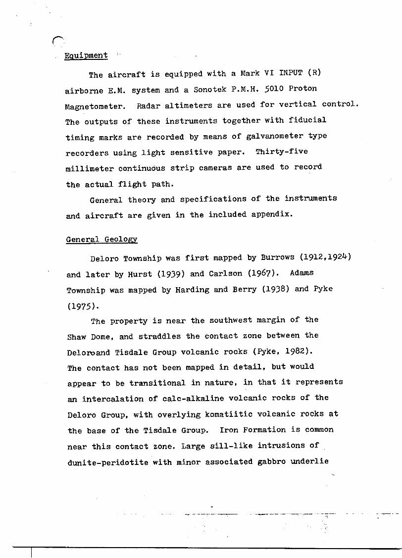
Figure I - Location of claims in Deloro - Adams Townships
Introduction
This report contains part of the results of an airborne
magnetic and electromagnetic (INPUT) survey flown by
Questor Surveys Limited in the Porcupine Area, about
six miles south of Timmins, for Comstate Resources Ltd.
The survey was flown on March 27, 1983, and covered most
of the south half of Deloro Township and a small portion
of north Adams Township (Figure 1). A total of 291.9
line kilometers was flown for the survey. The survey air
craft was a Shorts Skyvan C-GDRG and the operating base
was Timmins, Ontario.
The main purpose of the survey was to aid in deciphering
the structure and stratigraphy of the area, and to provide
a high quality data base for further exploration in the
area.
The following were the personnel involved with the
airborne survey:
Pilot B. McKenna
Co-pilot B. Jurgens
Operator D. Borsoi
Engineer S. Mills
Crew Chief D. Martyn
cA geophysical report on the airborne survey was
submitted to Comstate Resources Ltd. by Questor Surveys Ltd.
The report was authored by David G. Rogers, geophysicist
with Questor Surveys. The author of this report, D.R.
Pyke, has extracted all relevant information from the
report of D.Rogers relating to the claim block currently
held by Comstate Resources in the south Deloro - north
Adams Township area.
The 84- mining claims comprising the Deloro - Adams
property are currently held in the name of D.R. Pyke.
Map Compilation
The base map for navigation and flight path recovery
was constructed from photographs obtained from the
National Air Photo Library in Ottawa, Ontario. The final
map was reproduced at a scale of 1:15000 on stable trans
parent film from which white prints can be made.
Fligh path recovery was accomplished by comparison
of the 35 mm continuous strip film with the mosaic, in
order to locate the fiducial points. Most picked points
are within 1200 metres.
Survey Procedure
Terrain clearance was maintained as close to 122
metres as possible, with the E.M. bird at approximately
45 metres above the ground. A normal S-pattern flight
rpath using approximately one-half kilometre turns was
used. The equipment operator logged the flight details
and monitered the insturments.
A line spacing of 200 metres was used for the survey,
with flight directions at N 15O E.
Tie lines were flown in an east-west direction
across the survey area to be utilized in the levelling of
the magnetic data. In addition, a ground magnetic base
station, Geometrics G-806, was used to moniter diurnal
variations.
Data Presentation
The data is presented in the following manner:
1) INPUT - The symbols used to designate the anomalies
are shown in the legend on the map sheet, and the anomalies
on each line are lettered in an alphabetical order in the
direction of flight. Their locations are plotted with
reference to the fiducial numbers on the analog record.
A sample record is included to indicate the method
used for correcting the position of the E.M. bird and to
identify the parameters that are used.
The input map has a photo mosaic base, is at a scale
of 1:15,00, and depicts all the flight lines.
2) Magnetic - The aeromagnetic data is presented in computer
contoured plan form of the total magnetic field, at a scale
of 1:15.000. The data, dependent on magnetic gradient, has
been contoured at 10, 50 and 250 gamma intervals.
rEquipment !
The aircraft is equipped with a Mark VI INPUT (R)
airborne E.M. system and a Sonotek P.M.H. 5010 Proton
Magnetometer. Radar altimeters are used for vertical control.
The outputs of these instruments together with fiducial
timing marks are recorded by means of galvanometer type
recorders using light sensitive paper. Thirty-five
millimeter continuous strip cameras are used to record
the actual flight path.
General theory and specifications of the instruments
and aircraft are given in the included appendix.
General Geology
Deloro Township was first mapped by Burrows (1912,1924)
and later by Hurst (1939) and Carlson (196?). Adams
Township was mapped by Harding and Berry (1938) and Pyke
(1975).
The property is near the southwest margin of the
Shaw Dome, and straddles the contact zone between the
Deloroand Tisdale Group volcanic rocks (Pyke, 1982).
The contact has not been mapped in detail, but would
appear to be transitional in nature, in that it represents
an intercalation of calc-alkaline volcanic rocks of the
Deloro Group, with overlying komatiitic volcanic rocks at
the base of the Tisdale Group. Iron Formation is common
near this contact zone. Large sill-like intrusions of
dunite-peridotite with minor associated gabbro underlie
r.much of the central portion of the township. Pervasive
carbonatization of a portion of these ultramafic sills
has produced a large sub-economic magnesite deposit near
the south central boundary of Deloro Township. Northeast
and northerly trending diabase dikes are common.
Numerous gold occurrences have been reported in the
south Deloro Township area. Production, however, has been
minor and essentially limited to the former Faymar Mine
in the north part of the Township.
Results
Magnetic Survey
Magnetic relief on the property is in the order of
2500 gammas.
The northern portion of the property is dominated
by a westerly trending magnetic anomaly which largely
correlates with a sill-like body of dunite-peridotite
as outlined by Carlson (1967). An ENE trending diabase
dike, (Carlson, 196?) tends to augment the anomaly;
numerous inflections on this anomaly represent NNW trending
diabase dikes, as do narrow anomalies elsewhere on the
property.
The magnetics are generally low in the east-southeast
portion of the property. Limited outcrop suggests this
portion of the claim group is largely underlain by
andesite - basalt.
Electromagnetic Survey
Most of the input responses detected on the property are situated in the north central portion, in the general vicinity of Shaw Creek (anomaly areas 4 and 6). Both zones have similar electromagnetic responses and possible geologic associations. They display low to moderate decay rates and are located at the edge or within a magnetic high. The stagger in intercept location and shape suggests flat or shallowly dipping sources. Virtually all these anomalies are either within what are interpreted from the magnetic data as being ultramafic intrusions or at the contact zones of ultramafic intrusions or diabase dikes.
Conclusions
The airborne survey has provided a good data base for further work in the area. Detailed geological mapping is an essential ingredient of any follow-up exploration, in order to more fully evaluate the electromagnetic and magnetic responses.
References
Burrows, A. G.
1912: The Porcupine Gold Area? Second Report; Ont. Bureau of Mines, Vol. 21, pt. l, p. 205-249. Accompanied by Map 21a. Scale l inch to l mile.
192^: The Porcupine Gold Area; Fourth Report;Ont. Dept. of Mines, Vol 33, pt. 2, 112 p. Accompanied by Map 33a, Scale l inch to 2000 feet.
Carlson, H. D.
196?: Geology of Ogden, Deloro and Shaw Townships; Ont. Dept. of Mines, Open File Report 5012, ll?p. Accompanied by Maps P 3^1, P 3^2, and P34-3. Scale l inch to i mile.
Hurst, M. E.
1939s Porcupine Area, District of Cochrane; Ont.Dept. of Mines, Map 4?a, Scale l inch to 2000 feet.
Pyke, D.R.
1975: Geology of Adams and Eldorado Townships,District of Timiskaming; Ont. Div. of Mines, G. R. 121, 51p. Accompanied by Map 227*4-. Scale l inch to f mile.
CERTIFICATE
I, D.E. Tyke, submit this document to certify that the following
statements are, to the "best of my knowledge, true and correct.
1. That I have extracted all the relevant information regard
ing the airborne geophysics, from a report authored by
David G. Rogers (geophysicist, Questor Surveys Limited)
for an airborne survey conducted by Questor Surveys Ltd.,
in Deloro and Adams Townships, for Comstate Resources Ltd.
The survey was flown on March 27, 1983.
2. That I am the author of the corresponding assessment
report entitled "Airborne Magnetic and Electromagnetic Survey,
3. That I have received the following university degrees in
geology:
B.Se. University of Saskatchewan 1959
M.Se. University of Saskatchewan 1961
Pfc.D. McGill University, Quebec 1967
4. That I have been working as a geologist in the general
Timmins area for 16 years, and I am familiar with the geology
of the area under consideration.
Respectfully submitted,
D. R. Pyke
A-1
APPENHTX A
BARRINGER/OUESTOR MARK VI INPUT^"' System
The INduced pulse Transient (INPUT) method is a system
whereby measurements are made, in the time domain, of a secondary
electromagnetic field while the primary field is between pulses.
Currents are induced into the ground by means of a pulsed primary
electromagnetic field which is generated from a transmitting loop
around the aircraft. By using half-sine wave current pulses
(Figure A-l) and a transmitter loop of large turns-area, a high
signal-to-noise ratio and the high output power needed for deep
penetration, are achieved.
Induced current in a conductor produces a secondary
electromagnetic field which is detected and measured after the
termination of each primary pulse. Detection of the secondary
field is accomplished by means of a receiving coil, wound on a
ferrite rod, mounted in a fibreglass shell called a "bird" and
towed behind and below the aircraft on 120 metres (400 feet) of
coaxial cable. The received signal is processed and recorded by
equipment within the aircraft.
The axis of the receiving coil is horizontal and parallel to
the flight direction. This optimizes the discrimination between
flat lying surficial conductors and bedrock conductors. The
secondary field is in the form of a decaying voltage transient.
A-2
measured in time, at the termination of the primary transmitted
pulse. The amplitude of the transient is proportional to the
amount of current induced into the conductor, the conductor
dimensions, conductivity and the depth beneath the aircraft.
The rate of decay of the transient is inversely proportional
to conductance. By sampling the decay curve at six different time
intervals and recording the amplitude of each sample, an estimate
of the relative conductance can be obtained. Transients due to
strong conductors such as sulphides and graphite, usually exhibit
long decay curves and are therefore commonly recorded on all six
channels. Sheet-like surface conductive materials, on the other
hand, have short decay curves and will normally only show a
response in the first two or three channels.
For homogeneous conditions, the transient decay will be
exponential and the time constant of decay is equal to the time
difference at two successive sampling points divided by the log
ratio of the amplitudes at this point.
r
A-3
TRANSMITTER SPECIFICATIONS
Pulse
Pulse
Pulse
Off
Repetition Rate
Shape
Width
Time
211 per sec
Half-sine
2.0 millisec
2.7 millisec
Output Voltage
Output Current
Output Current Average
50 volts
300 amperes
80 amperes
Coil Area
Coil Turns
Electromagnetic Field Strength (peak)
190 m. 2 (2,050 ft. 2 )
6
342,000 amp-turn-meter2
INPUT SIGNAL
TRANSMITTED PRIMARY FIELD
Figure Al
A-4
RECEIVER SPECIFICATIONS
Sample Gate Windows (centre positions)
CH l CH 2 CH 3 CH 4 CH 5 CH 6
300 p sec500800
1200 1700 2300
Sample Interval
Integration Time Constant
Bird Position behind Aircraft (110 kt)
Bird Position below Aircraft (110 kt)
Widths
200 V 6ec200400400600600
0.5 sec
1.1 sec
93 metres
69 metres
Receiver features: Power Monitor 50 or 60 Hz
50 or 60 Hz and Harmonic Filter
VLF Rejection
Spheric Rejection (tweak) Filter
SAMPLING OF INPUT SIGNAL
Figure A2 - Channel cvntt**
A-5
ri
SQNOTEK P.H.H. 5010 PROTON MAGNETOMETER
The airborne magnetometer is a proton free precession
sensor r which operates on the principle of nuclear magnetic
resonance to produce a measurement of the total magnetic
intensitity. It has a sensitivity of l gamma and an operating
range of 20,000 gammas to 100,000 gammas. The sensor is a solenoid
type, oriented to optimize results in a low ambient magnetic field.
The sensor housing is mounted on the tip of the nose boom
supporting the INPUT transmitter cable loop. A 3-term compensating
coil and perma-alloy strips are adjusted to counteract the effects
of permanent and induced magnetic fields in the aircraft.
Because of the high intensity electromagnetic field produced
by the INPUT transmitter, the magnetometer and INPUT results are
sampled on a time-share basis. The magnetometer head is energized
while the transmitter is on, but a measurement is only obtained
during a short period when the transmitter is off. Using this
technique, the sensor head is energized for 0.80 seconds and
subsequently the precession frequency is recorded and converted to
gammas during the-following 0.20 seconds when no current pulses are
induced into the transmitter coil.
A-6
DATA ACQUISITION SYSTEM ,.
Sonotek SDS 1200
9 track 800 BPI ASCII
Includes time base Intervalometer, Fiducial System
Geocam 75 SP
35 mm continuous strip or frame
TAPE DRIVE
Digidata Model 1139
OSCILLOSCOPE
Tektronix Model 305
ANALOG RECORDER
Honeywell Visicorder WS 4010
Kodak Light Sensitive Pape (15cm)
Recording 14 Channels: 50-60 Hz Monitor, 6 INPUT Channels, fine
and coarse Magnetics, Altimeter, vertical and horizontal timing
lines and fiducial markers.
ALTIMETER
Sperry Radar Altimeter
A-7
HONEYWELL ANALOGUE CHART RECORDER
SONOTEK DATA SYSTEM
TRACK TAPE RECORDER
RADAR ALTIMETER
3Smm T RACKING CAMERA
INPUT EQUIPMENT INSTALLATION
- J
TOWED 'BIRD' ASSEMBLY
INTERFACE. OSCILLOSCOPE t T.C.U.
TRANSMITTER
MK V I INPUT RECEIVER
'BIRD* WINCH
QUESTOR/BARRINGER MARK VI "INPUT" SYSTEM EQUIPMENT
APPENDIX B
The Survey Aircraft
Manufacturer
Type
Model
Canadian Registration
Figure Bl
Short Brothers Ltd.
SHORT SKYVAM
SH-7 Series 3
C-GDRGDate of INPUT Installation October 1981
Modifications:
1) Nose, tail and wing booms for coil mounting2)
3)
4)
Long range cabin fuel tank i 8 hours of air time Winch, camera and altimeter portsSperry C-12 navigational system
5) Doppler navigational system
6) Capable of spectrometry
7) Modified hydraulic driven generator systenThe SKYVAN is a short take-off and landing aircraft. It is
powered by two low maintenance turbine engines. The configuration of the aircraft provides for easy installation of equipment and extra fuel capability. These factors have proven the SKYVAN to be a reliable and efficient geophysical survey aircraft.
ASSESSMENT WORK BREAKDOWN
1. Type of Survey .
2. Township or Area -.
3. Numbers, of Mining Claims Traversed by Survey . ..^L^fi^i^,^^-^^^^
4. Number of Miles of Line Cut __.
*5. Number of Stations Established .
*6. Make and type of Instrument Used ^QQ
*7. Scale Constant or Sensitivity ,.
*8. Frequency Used and Power Output
Flown
9. Summary of Assessment Credits (details on reverse side)
Total 8 hour Technical Days (Include Consultants, Draughting etc.)
Total 8 hour Line-Cutting Days ___......._-..
Calculation
x 7 * + = 4-Technical Line- cutting Number
of claimsAssessment credits
per claim
The dates listed on this form represent working time spent entirely within the limitsof the above listed claims [ l CheckIf otherwise, please explain _ ......................... _ ;..... _ _ ..................
Dated: ,.
Note: (A) * Complete only if applicable.(B) Complete list of names, addresses and dates on reverse side.(C) Submit separate breakdown for each type of survey.
1 (D) Submit in duplicate.
Ministryof
Ontario
Report of Work(Geophysical, Geological, Geochemical and Expenditures) 4aA86NE848S 2 .5739 DELORO
T. .. —— TcX. The Mining Act C^,^
9(2)0i my OB enteredI in the "Expend. Days Cr." columns.
__ DoDo not use shaded areas below.Type of Surveyd)
S S1 ") Township or Area
Claim Holdar(i) Prospector'1 Licence No.
Addren
(Osvr. ^3 dDate of Survey (from Si to)
Day l Mo. | Yr. | Day | Mo. | Yr.
Survey Companv Total Miles of lin* Cut
Name and Address of Author (of Geo-Technlcal report)
Credits Requested per Each Claim in Columns at rightSpecial Provisions
For first survey:Enter 40 days. (This includes line cutting)
For each additional survey: using the same grid:
Enter 20 days (for each)
Geophysical
- Electromagnetic
- Magnetometer
Days per Claim
3 ic83Geochemical
Man Days
Complete reversj side and eijtar tot'ell?) here
Note: Special provisions credits do not apply to Airborne Surveys.
Electromagnetic
Magnetometer
Radiometric
Days per Claim
Expenditures (excludes power stripping)Type of Work Performed ( V ,.-,iC-ri
-~- ••""" "r,|NE f.''i' llfl ", ;rr\ \Performed on Glajtn(s) i Ir1, \ \* ' \ 'j *-' \\ i ' \i TO) E. w UJ , ..' \
1 du - () ,. ^ ^ - " , \Calculation of Expenditure Days Credits ^, " 'i M\, ,, ^r/r'i 1 v.'i'- i 1 ' ~^L^-~-Total Expefjdltujres;!'. '-. ;^^-— — — "^~"
S ''^^ -i- 15
L —— l Totel Days Credits
-
Instructions Total Days Credits may be apportioned at the claim holder's choice. Enter number of days credits per claim selected in cplu^nns et right.
Date Jfa Reco
Certification Verifying Report of Work
Mining Claims Traversed (List in numerical sequence)Mining Claim
Prefix Number
59; j 4- D
42.
59; J 44.
597/07
597;;;
Expend. Days Cr.
Mining ClaimPrefix Number
o
t-./o 7;3
6 28 S/ J
Expend. Days Cr.
Total number of mining claims covered by thii report of work.
f̂ -r J(VC l 'O l
Total Days Cr. Date Recorded Recorded
l hereby certify that l have a personal and intimate knowledge of the facts set forth in the Report of Work annexed hereto, having performed the work or witnessed same during and/or after its completion and the annexed report is true.Name and Postal Address qfPerson Certifying
M
cd/~^.
.51
4 k
. i -
c-''
M
M^ NO
fi
(M^rrjV
Ministry of Natural
_ Ragflurces Ontario J^
GeotechnicalReportApproval
File
Mining Lands Comments
lo: Geophysics
Comments
[~1 Wish to see again with correction*
To: Geology - Expenditures
Comments
i Approved f~\ W ish to see again with correctionsDate Signature
DTo: Geochemistry
Comments
[~j Approved f~l Wish to see again with correctionsDate Signature
Mr. UIIHaM L. GoodMining RtcordtrMinistry of Natural Resources60 Milton AvtnutTlMMlns. OntarioP4N 2S7
Otar Sir:
Mt havt rtctlvtd rtports and naps for an Alrbornt fitophyslcal (EltctroMagnttlc and MagnttoMtttr) survty subnltttd on •Inlng claim P 591138 tt al In tht Townships of Deloro and AdaMS.
This Material will bt txanlntd and asstsstd and a stattMnt of asstssMtnt work crtdlts will bt Issutd.
Ministry of Natural ResourcesGEOPHYSICAL - GEOLOGICAL - GEOCHEMICAL
TECHNICAL DATA STATEMENT
File.
TO BE ATTACHED AS AN APPENDIX TO TECHNICAL REPORTFACTS SHOWN HERE NEED NOT BE REPEATED IN REPORT TECHNICAL REPORT MUST CONTAIN INTERPRETATION, CONCLUSIONS ETC.
Type of Survey(s) Township or Area Claim Holder(s)
Survey r-nmpany
Author of Report AddressCovering Dates of Survey.
Total Miles of Line Cut —
MINING CLAIMS TRAVERSED List numerically
(linecutting to offiot)
SPECIAL PROVISIONS CREDITS REQUESTED
ENTER 40 days (includes line cutting) for first survey.ENTER 20 days for each additional survey using same grid.
OTHERS (SEISMIC, DRILL WELL LOGGING ETC.) Type of survey_________________________ Instrument ̂ ^—^^——^-——-—^^^-^^^^-——— Accuracy^^————-—^^—-—^^^^^————————Parameters measured.
Additional information (for understanding results).
AIRBORNE SURVEYS Type of sinwy( s) A/
Instrument(s)(specify for each type of survey)
Arnirary(specify for each type of survey)
Aircraft . .^H -g^O/3 r -Sf i) A A)
SensorNavigation and flight path recovery
TiuAircraft altiti.He .2.Sn*3ef^ __________________ Line SpacingMiles flown over total arpa /8)*4- f^Si'S /s/) A /g/A^^ia^sJOver claims only 42.. f