Art 252: Definitions /Art 253: Safety devices the car such as presented on the starting grid, for event considered. U) Refuelling procedure-Standardised coupling: In case of a centralised system provided by the circuit, or a system provided by the competitors, the refuelling hose shall be provided with a leak-proof coupling to fit the standar- dised filler mounted on the car. The dimensions of this filler are given in the diagram shown on page 11 0. All cars must be provided with a fuel filler complying with the diagram shown on page 11 0. The leak-proof filler must comply with the dead man principle and must not therefore incorporate any retaining device when in an open position (spring-loaded, bayonet, etc). The air-went(s) must be equipped with non return valves and valves having the same closing system as that of the standard filler, and of the same dia- meter. During refuelling the outlet of the air-vent must be connected with the appropriate coupling, either to the main supply-tank or to a transparent port- able container with a minimum capacity of 20 litres provided with a closing system rendering it completely leak-proof. The venting catch tanks must be empty at the beginning of the refuelling procedure. In the case where the circuits are unable to provide the entrants with a centralised system, these will have to refuel according to the above procedure. In no case the level of the reserve tank may exceed three metres above the track where the refuelling takes place, for all the duration of the event. Application: Please refer to the General Prescriptions of the FIA Champion- ships. v) : Stock block engine vl) : Maximum cylinder capacity: 5000 cm3. v2) : Engine whose series production will have been checked by the FIA as being 5,000 units a year, and mounted on (a) series production car(s). v3) : Engine with valves operated by rockers and pushrods. v4) : Use of the original cylinder head. The number and location of the origi- nal camshaft(s) may not be changed. The number of valves may not be changed. The valve angle and the angle of the intake and exhaust ports may not be changed in relation to the cylinder axis. v5) : Use of the original block. The number of main bearings may not be changed. v6) : Supercharging prohibited. TITLE 3--SAFEBY PRESCRIPTIONS Art 25SSafety devices for all cars competing in events entered on the FIA lnternatlona! Calendar A car, the construction of which is deemed to be dangerous, may be excluded by the Stewards of the meeting. If a device is optional, it must be fitted in a way that complies with regula- tions. a) Supplementary locking devices. A supplementary locking device(s) for
Transcript
Art 252: Definitions /Art 253: Safety devices
the car such as presented on the starting grid, for event considered.
U) Refuelling procedure-Standardised coupling: In case of a centralised system provided by the circuit, or a system provided by the competitors, the refuelling hose shall be provided with a leak-proof coupling to fit the standar- dised filler mounted on the car. The dimensions of this filler are given in the diagram shown on page 11 0.
All cars must be provided with a fuel filler complying with the diagram shown on page 11 0. The leak-proof filler must comply with the dead man principle and must not therefore incorporate any retaining device when in an open position (spring-loaded, bayonet, etc).
The air-went(s) must be equipped with non return valves and valves having the same closing system as that of the standard filler, and of the same dia- meter.
During refuelling the outlet of the air-vent must be connected with the appropriate coupling, either to the main supply-tank or to a transparent port- able container with a minimum capacity of 20 litres provided with a closing system rendering it completely leak-proof. The venting catch tanks must be empty at the beginning of the refuelling procedure.
In the case where the circuits are unable to provide the entrants with a centralised system, these will have to refuel according to the above procedure. In no case the level of the reserve tank may exceed three metres above the track where the refuelling takes place, for all the duration of the event.
Application: Please refer to the General Prescriptions of the FIA Champion- ships.
v) : Stock block engine vl ) : Maximum cylinder capacity: 5000 cm3. v2) : Engine whose series production will have been checked by the FIA as
being 5,000 units a year, and mounted on (a) series production car(s). v3) : Engine with valves operated by rockers and pushrods. v4) : Use of the original cylinder head. The number and location of the origi-
nal camshaft(s) may not be changed. The number of valves may not be changed. The valve angle and the angle of the intake and exhaust ports may not be changed in relation to the cylinder axis.
v5) : Use of the original block. The number of main bearings may not be changed.
v6) : Supercharging prohibited.
TITLE 3--SAFEBY PRESCRIPTIONS
Art 25SSafe ty devices for all cars competing in events entered on the FIA lnternatlona! Calendar
A car, the construction of which is deemed to be dangerous, may be excluded by the Stewards of the meeting.
If a device is optional, it must be fitted in a way that complies with regula- tions.
a) Supplementary locking devices. A supplementary locking device(s) for
obader
Texte surligné
Art 253: Safety devices
engine bonnet, boot iid and other important objects carried -on board of the vehicle (such as a spare-wheel, tool set, etc).
Application: Compulsory for cars of Groups 1, 2, 3, 4, 5.
b) Supplementary protection of the pipes: A supplementary protection of fuel pipes and brake lines outside the coachwork against any risk of damage (stones, corrosion, breaking of mechanical pieces, etc) and inside the cockpit against any risk of fire (fuel pipes only).
Application: Compulsory for cars of Groups 1, 2, 3, 4, 5 and 6. However, in Groups 1 to 4, if the series production fitting is kept, no additional protection will be necessary.
Cables, lines and electrical equipment : Except if the cables, lines and elec- trical equipment such as battery, fuel pump, etc, are in compliance with the requirements of the aircraft industry as regards their location, material and connections, they must be placed or fitted in such a way that any leakage cannot result in:
-Accumulation of liquid. -Entry of liquid into the cockpit. -Contact .between liquid and any electrical line or equipment. S h ~ u l d the cables, lines or electrical equipment pass through or be fitted in
the cockpit, they must be fully enclosed in a cover of a liquid-tight and fire- proof material.
All fuel lines external to the cockpit, with the exception of fuel lines perma- nently mounted on the engine, should be a reinforced construction, attached by screw-on connectors. They must withstand a 70 kg/cm2 pressure (1,000 psi) and a 230" C temperature.
All electrical wiring should be enclosed in a fire-proof material.
Application: Compulsory for cars of Groups 6, 8.
c) Safety belts: Wearing of one diagonal strap and one abdominal strap fixation points on the shell: 3.
Application: Compulsory for all cars of Groups 1, 2, 3 and 4 participating in rallies.
Wearing of two shoulder straps and one abdominal strap: fixation points on the shell: two for the abdominal strap - two or eventually one symmetrical in relation to the seat for the shoulder straps.
Application: Compulsory for all cars of Groups 1, 2, 3 and 4 (except in rallies).
It is permitted to make a hole in a series-prod uction seat to allow the passing of a safety belt.
Wearing of two shoulder straps, one abdominal strap and two straps bet- ween the legs: fixation points on the body; two for the abdominal strap, two or eventually one symmetrical in relation to the seat for the shoulder straps, two for the straps between the legs.
Application: Compulsory for all cars of Groups 5, 6 and 8.
Art 253: Safety devices
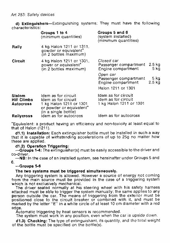
d) Extinguishers-Extinguishing systems: They must have the following characteristics:
Groups 1 to 4 Groups 5 and 6 (minimum quantities) (system installed)
(minimum quantities)
Rally 4 kg Halon 1211 or 1311, powder or equivalent* (in 2 bottles maximum)
Circuit 4 kg Halon 121 1 or 1301, Closed car power or equivalent* Passenger compartment 2.5 kg (in 2 bottles maximum) Engine compartment 5 kg
Open car Passenger compartment 5 kg Engine compartment 2.5 kg Halon 121 1 or 1301
Slalom ldem as for circuit ldem as for circuit Hill Climbs ldem as for circuit ldem as for circuit Autocross 1 kg Halon 1211 or 1301 1 kg Halon 121 1 or 1301
or powder or equivalent* (in a single bottle)
Rallycross ldem as for autocross ldem as for autocross
*Equivalent: a product having an efficiency and non-toxicity at least equal to that of Halon (1 21 1).
dl.1) Installation: Each extinguisher bottle must be installed in such a way that it is capable of withstanding accelerations of up to 259 no rnatter how these are applied. d1.2) Operation triggering: -Groups 1-4: The extinguisher(s) must be easily accessible to the driver and
CO-d river. -NB: In the case of an installed system, see hereinafter under Groups 5 and
6. --Groups 5-6 The two systems must be triggered simultaneously. Any triggering system is allowed. However a source of energy not coming
from the main source must be provided in the case of a triggering system which is not exclusively mechanical.
The driver seated normally at his steering wheel with his safety harness attached must be able to trigger the system manually; the same applies to any person outside the car. The means of triggering from the exterior must be positioned close to the circuit breaker or combined with it, and must be marked by the letter "E" in a white circle of at least 10 cm diameter with a red edge.
Automatic triggering by heat sensors is recommended. The system must work in any position, even when the car is upside down. d1.3) Checking: The type of extinguishant, its quantity, and the total weight
of the bottle must be specified on the bottle@).
Art 253: Safety devices
cf2) Cars of Groups 1,2,3,4. (Circuit or Rally): Cars of Groups 1 to 4 must be equipped with one or two bottles containing a
minimum of 4 kg of the extinguishant Halon 121 1 or 1301 (BCF-BTM), powder, or equivalent.
An extinguisher system as provided for in point d3 is allowed d3) Cars of Groups 5 and 6 (Circuit): Minimum capacities of extinguisher systems --Closed cars: cockpit: 2.5 kg
engine: 5 kg -Open cars: cockpit: 5 kg
engine: 2.5 kg The extinguishant must be Halon 1211 or 1301 (BCF-BTM) only. Extinguishing equipment must withstand fire and be protected against
im acts. f h e extinguisher system nozzles must be installed in such a way that they are
not directly pointed at the driver (danger of burns caused by cold). Discharge time: cockpit: 30 secs for Halon 121 1, 60 secs for Halon 1301
engine: I Q secs d4) Group 8 cars: The extinguisher system for national Formulae is left up to
the ASNs. However the directives laid down in d3 are strongly recommended. e ) Safety roll-bars: General considerations 1) The basic purpose of such devices is to protect the driver if the car turns
over or is involved in a serious accident. This purpose should always be borne in mind.
2) Whenever bolts and nuts are used, the bolts should be of a sufficient minimum diameter, according to the number used. They should be of the highest possible quality (preferably aircraft). Square head bolts and nuts should not be used.
3) One continuous length of tubing should be used for the main structure with smooth continuous bends and no evidence of crimping or wall failure.
4) A11 welding should be of the highest quality possible with full penetration (preferably arc welding and in particular heliarc). Although good outside appearance of a weld does not necessarily guarantee its quality, poor looking welds are never a sign of good workmanship.
5) Braces should preferably be of the same size tubing as used for the main structure.
Their fixation should be located as near as possible to the top of t h e h l bar. in any case at a minimum of 3?4 of the total height of the roll bar.
6) For space-frame constructions it is important that crash-bar structures are attached to cars in such a way as to spread the loads over a wide area. It is not sufficient to simply attach the roll-bar to a single tube or junction of tubes. The roll-bar should be designed in such a way as to be an extension of the frame itself, not simply an attachment to the frame.
Considerable care should be attached to the necessary strengthening of the basic structure, for instance by adding reinforcement bars or plates so as to properly distribute the loads.
7) For monocoque constructions, consideration should be given to using a
Art 253: Safety devices
roll-bar hoop of 360 degrees completely around the inside of the car, and attached with suitable mounting plates. This type of roll-bar then becomes a substitute for the frame.
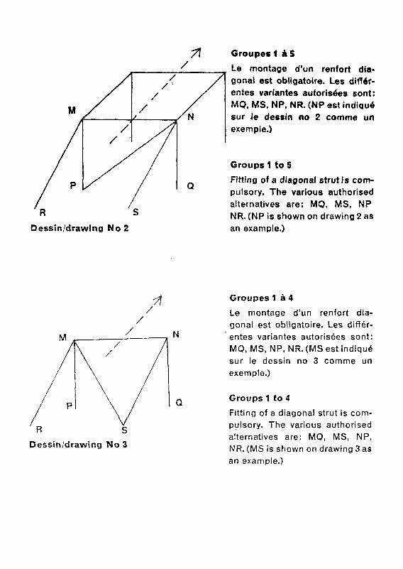
A) Closed cars: As a general rule, the safety cage must be made of two main hoops, one
behind the front seats and one following the windscreen pillars (see drawing No 2). For some groups of cars, (see hereunder) the windscreen hoop is not compulsory and the designing may be realised as shown in drawing No 3.
The safety roll-bar or cage must be conceived in such a way as not to obs- truct the access to the front seats and not encroach on the space provided for the driver and the passenger. On the other hand, it is allowed that the elements of the roll-bar or cage encroach on the space of the rear passengers, and pass through the upholstery or the rear seat(s).
The main roll-bar hoop@) must be placed as near as possible to the roof in order to limit its crushing in the event of a somersault.
In order to avoid an important deformation of the coachwork and conse- quently protect more efficiently the driver in case of a lateral impact, i t is possible to enhance the efficiency of the safety roll-bar, thanks to the mounting of a longitudinal support at the door level.
The tube constituting this support should be integrated in the safety framework, the front and rear hoops of which it connects, and to which it is fitted, either by welding or with a removable coupling; it cannot be fixed on the coachwork itself.
Its diameter, its thickness and its material correspond to the specifications of the FIA for safety roll-bars. Its angle with the horizontal should not exceed 5". It should divide the height of the opening of the door in the relation 2:1, ie, it is fitted on the framework at a height equal to 1/3rd of the total height of the door above the door sill.
B) Open cars: Conception and realisation identical to those prescribed for closed cars.
Moreover, the main hoop behind the front seats must be symmetrical about the lengthwise centre-line of the car and comply with the following figures (see drawing 10):
Height: The top of the roll-bar must be at least 5 cm (2 in) over the helmet of the driver normally sat at his wheel.
Width: Measured on the inside of the vertical struts of the roll-bar; there must be at least 20 cm (8 in) measured at 60 cm (23 in) above the driver's and passenger's seat (on the line perpendicular to the driver's vertebrae from the lengthwise centre-line to the outside).
Lengthwise location: The lengthwise distance between the top of the roll- bar and the helmet of the driver normally sitting at his steering wheel must not exceed 25 cm.
Will also be considered as open cars, cars which have no structural parts between the upper part of the windshield framework and that of the rear win- dow, if any.
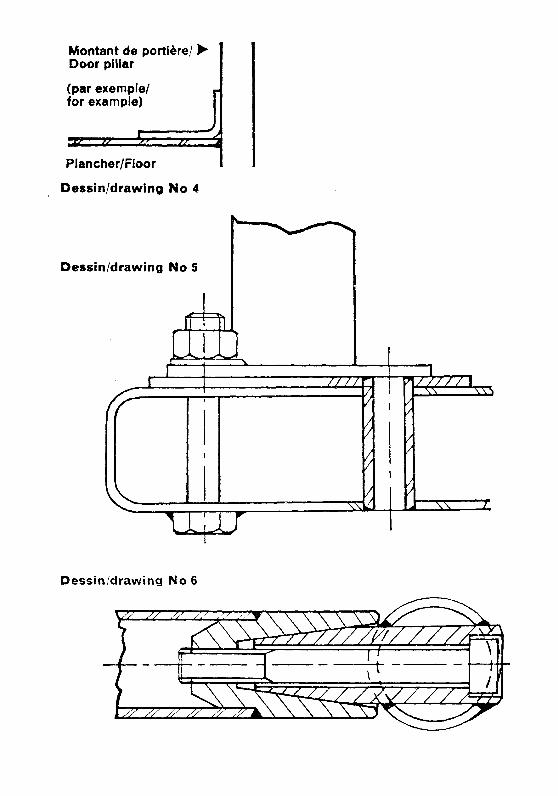
C) Attachment of roll-over bars on the body: It is specified that roll-over bars must make use of two plates: -a steel piate, welded, riveted, or bolted on to the chassis body shell, at least
2 mm thick, with a prolongation along a vertical component of the body (for instance, a door pillar: see drawing 4).
71 Grouper f S / Le montage d'un renfort dia-
gonal est obligatoire. Les differ- entes variantes autorishs sont: MQ, MS, NP, NR. (MP est indiqud sur Je dessln no 2 comme un exemple.)
Groups 1 to 5
Fitting of a diagonal strut i s corn- pulsory. The varlous authorised alternatives are: MQ, MS, NP NR. (NP is shown on drawing 2 as
Dessinldaawing No 2 an example.)
Groupes 1 8 4
Le montage d'un renfort dia- gonal est obligatoire. Les differ- entes variantes autorisees sont: MQ, MS, NP, NR. (MS est indiquk sur le dessin no 3 comme un exemple.)
Groups 1 to 4
Fitting of a diagonal strut is com- pulsory. The various authorised alternatives are: MQ, MS, NP, NR. (MS is shown on drawing 3 as an example.)
Montant de porti&el b Door pillar 1 (par exempiet for example)
Dessinldrawing No fa: En dehors de la structure princ structure.
ipale/Outside the ma
Dessin/drawing No 8 12 mm (tube < 40 mm diam. ext) 4 = 44 mm (tube 2 40 mm < 50 m m diam. ext)
16 mm (tube 2 50 mm diam. ext)
Groupe 6 Le montage d'un rentort dia- gonal est obligatoire. Les 2 variantes autorisbes sont MO et NP. (NP est indique sur le dessin no 9 cornme un exemple.)
Group 6 Fitting of a diagonal strut is com- pulsory. The 2 authorised alter- natives are MQ and NP. (NP is shown on drawing 9 as an example.)
Art 253: Safety devices
This plate must have a total surface of at least 35 cm2, a third of which at least constitutes the link with the vertical body component.
-a plate attached to the tube, having the same thickness as the metal of the tube to which it is fixed.
These two plates shall be joined together by at least three hexagonal headed bolts and nuts, at least 8 mm in diameter, or by at least three high tensile Allen head cap screws and nuts, at least 8 mm in diameter.
In no case may the roll-over bar be welded directly on to the body shellkhas- sis.
When the roll-bar rests on a box-member, the latter must be locally reinfor- ced by a structure constituted of either welded bolts or welded tubing ends (see drawing 5).
In the case where the roll-bar is su ported on a rear shelf which is not rigid enough, the roll-bar must be strengtiened by adding struts. which must con- form to roll-bar specifications (material, connections, fixation) between this rear shelf and car's monocoque.
D) Removable connections: In case removable connections are used in the roll-bar construction, they
must comply with a type approved by the FIA. Are approved up to now: a tapered connection and a twin lug connection with axls working under double shearing conditions and a muff-connection complying with drawmgs 6,7 and 8.
The twin lug connection may however be used only for longitudinal brace- rods and not for the basic frame of the roll-bar(s).
The connection in accordance with drawing 7a may be used outside the main structure.
E) Application:
Spec[Rcations of the tubes utilised (Groups 1 to 5)
Closed cars Open cars <1,200 kg 21,200 kg 4 , 2 0 0 kg 21,200 kg
Ext. 0 X thickness
Cold drawn seamless carbon steel E - 30 daN
Alloy steel type 25 CD 4 8 33.7 0 42.4 0 38 0 48.3 SAE 4125 etc, E - 50 daN X 2.3 X 2.6 X 2.6 , X 2.6
These dimension figures represent in mm the minimum figures admissible. They correspond to standardised tubes (International Standards IS0 R 64).
In the case of cars weighing more than 1,200 kg, the dimension figures prescribed for cars weighing less than 1,200 kg may be used for tubular elements other than the main hoop located behind the front seats.
NB: The FISA, conscious of the problem of habitability raised by the use o f roll cages, suggests that each car manufacturer recommends a type of roll-bar complying with FIA Specifications for all cars in Groups 1 to 4.
This roll-bar will have to be entered on a recognition sheet amendment and submitted to the FISA for approval.
Important: The exact weight of the device shall be subject to a statement
Art 253: Safety devices
from the competitor, to be appended to the entry form. th is weight must be added to that indicated for the vehicle on the recognition form.
Application: Groups 1 and 3. Cars of Groups 1 and 3: Fitting compulsory for all speed events on circuits. Fitting optional for rallies,
hill-climbs and slaloms. However, should the organisers of a rally or hill-climb deem that the driving conditions during their event are comparable to those of a speed event, they are entitled to prescribe the compulsory fitting of a safety roll-bar or cage, even for cars of Groups 1 and 3. This obligation must, in that case, be clearly mentioned in the Supplementary Regulations of the events.
Cars of Groups 2 and 4: Fitting compulsory for all events. In rallies, the diagonal strut is not compul-
sory. The safety cage, as shown in drawing No 2, provided for cars whose weight
exceeds 1,200 kg, is compulsory for all cars whose cylinder-capacity exceeds 2 l it res.
Cars of Group 5: Fitting compulsory for all cars. The safety cage as shown in drawing No 2,
provided for cars whose weight exceeds 1,200 kg, is compulsory. Cars of Group 6: All cars should be equipped with a safety roll-bar symmetrical about the
longitudinal axis of the car. In cars fitted with doors, the roll-bar will have a minimum height of 92 cm
measured vertically from the lowest point of the entirely sprung structure of the car.
In cars without any door, the minimum height will be 120 cm. In any case, the top of the roll-bar must be at least at 5 cm above the driver's helmet when the driver is sitting in normal driving position.
Manufacturing of roll-bars, in conformity with the following table and drawings 9 and 10 (International Standards IS0 R 64 except for @ 35 x 2), and to previous specifications concerning the removable connections and the gen- eral considerations.
The mounting of front stays to protect the driver is accepted on condition that they are removable, for open cars.
.It is recalled that the safety roll-bar must be symmetrical about the lengthwise centre line of the car.
(Group 6) Cold drawn seamless carbon steel E - 30 daN
Closed and Open Cars c700 kg 3700 kg a
Alloy Steel type 25 CD4 SAE 41 25 etc E - 50 daN
- -- P p-- -
However, recognised and traditional manufacturers may also present a roll-
Art 253: Safety devices
bar of free conception as regards the material used, the dimensions of the tubes and the implantation of the braces, providing that the construction is certified to withstand stress minima given hereafter.
W being the weight of the car in starting order (driver aboard, full tanks),'the roll-bar must be able to withstand three simultaneously applied loads:
-1 5 W lateral, -5.5 W fore and aft, -7.5 W vertical, these loads being carried over into the primary structure of
the chassis. A certificate signed by a qualified technician must be submitted to the
Scrutineers of an event. It must be accompanied by a drawing or a photograph of the said roll-bar and state that this roll-bar can withstand the absve men- tioned loads.
Cars of Group 8: Dimensions: The dimensions of the roll-bars must be as follows: the
minimum height must be at least 36 inches (92 cm) measured along the line following the driver's spine, from the seat's metal shell to the top of the roll-bar. The top of the roll-bar must also be at least at 5 cm above the driver's helmet when the driver is sitting in normal driving position. The width must be at least 38 cm measured inside the roll-bar between the two vertical pillars of the sides. It must be measured at 60 cm above the seat's metal shell on the perpendicular to the line following the driver's spine.
Strength: In order to obtain a sufficient strength for the roll-bar, two pos- sibilities are left to the manufacturers:
a) The roll-bar, of entirely free structural conception, must be capable to withstand the stress minima indicated on the scale hereabove (5 concerning cars of group 6).
b) The tubes and brace(s) must have a diameter of at least 1% inch (3.5 cm) and at least 0.090 inch (2 mm) wall thickness. The material should be molyb- denum chromium SAE' 4130 or SAE 4125 (or equivalent in DIN, NF, etc).
There must be at least one brace from the top of the bar rearwards at an angle not exceeding 60" with the horizontal. The diameter and material of the brace must be the same as those of the roll-bar itself.
In the case of two braces, the diameter of each of them may be reduced to 20/26 mm. Removable connections between the main hoop and the brace must comply with drawings No 6, 7, 7a, or with any other type approved by the FIA.
Forward fitted stays are allowed. f) Safety fuel tanks approved by the FIA: Entrants must use safety fuel tanks made by a manufacturer recognised by
the FIA. In order to obtain the FIA's agreement, a manufacturer must have proved the constant quality of its product and its compliance with the specifi- cations approved by the FIA.
Safety tank manufacturers recognised by the FIA must undertake to deliver to their customers exclusively tanks complying with the norms approved. To this end, on each tank delivered there shall be a printed code indicating the name of the manufacturer, the exact specifications according to which this tank has been manufactured and the date of the manufacturing.
1) Technical specifications: The FIA reserves its right to approve any other set of technical specifications
Art 253: Safety devices
after study of the dossier submitted by the manufacturers concerned. 2) Specifications FIA/Spec/FTS: The technical specifications for these tanks are available, on request, from
the FlSA Secretariat. Ageing of tanks The ageing of safety tanks entails a considerable reduction in the strength
characteristics after approximately five years. Therefore, all fuel cells must be replaced by new ones at the latest five years
after the fabrication date indicated on the cell. 3) Specifications FI AISpecl FTA: The technical specificat~ons for these tanks are available, on request, from
the FlSA Secretariat. For reasons of vibrations, the fuel tank, i f it is not made of rubber or of other
elastic materials, should be suspended from the chassis by means of elastic supports (of a type similar to those used for the water radiators).
Note: In case this specification of fuel tanks would be used for cars of Group 6 the fitting of crushable structure would become optional.
4) List of recognised manufacturers Federal Republic of Germany Uniroyal, 51 00 Aachen, Postfach 41 0 United States Don Allen Inc, 401 Agee Road, Grants Has, Oregon 97526. Aero Tec Labs, Hewson Avenue, Warcick, NJ 07463. Fuel Safe Corporation, 15545 Computer Lane, Huntingdon Beach, California
92649 Goodyear Fuel Cell Labs, The Goodyear Tire and Rubber Company, Akron,
Ohio 44316 France Kkber-Colombes Division Tissus Enduits et Applications, 4 rue Lesage
Maille, 76 230 ,Caudebec-les-El beuf Ets J. RICHE-BP 14-1 4690 Pont-d'ouilly. Superflexit SA, 45, rue des Minimes, 92-Courbevole Great Britain FTP Industries Ltd, The Airport, Portsmouth, Hants Marston Excelsior Ltd, Wobaston Rd, Wolverhampton, Staffs Premier Fuel Systems Ltd, Burnaston Old Airfield, Burnaston, Derby Woodvil le Rubber Company Ltd, Hearthcote Road, Swad lincote, Burton-
on-Trent, DEl l 9DX. Italy Autodelta SpA (Alfa Romeo), Via Enrico Fermi 7, 20019 Settimo-Milanese Pirelli, Viale Rodi 15, Milano Japan Kojima Press Ltd, 3-30 Shimolchibacho Toyota, Aichiken Sakura Rubber CO Ltd, 48-14-1 Chome Sasazuka, Shibuya Ku, Tokyo Sumitomo Electric Industries Ltd, 15-5 Chome Katahama, Migashi Ku, Osaka 5) Application of the different specifications Cars of Groups 5-6-8: Compulsory fitting of a FT3 or FTA fuel tank in all
events. Cars of Groups 1-2-3-4: The cars of Groups 1 to 4 may be equipped with a
Art 253: Safety devices
safety fuel tank, on condition that the necessary internal modifications do not affect the structural parts and the suspension mountings.
g) General circuit breaker: The 'general circuit breaker must cut all electri- cal circuits (battery, alternator or dynamo, lights, hooters, ignition, electrical controls, etc). It must be of a spark-proof model, and will be accessible from inside and outside the car. As for the outside, the triggering system o f the circuit breaker will compulsorily be situated at the lower part of the windscreen mounting on the driver's side for closed cars, at the lower part of the main hoops of the roll-6ar, indifferently on the right or the left, for open cars. It will be marked by a red spark in a white-edged blue triangle with a base of at least 12 cm.
Application: Compulsory fitting for all cars taking part in speed events on circuits or hill-climbs. The fitting is recommended for other events.
h) Oil catch tank: When cars are running in events which are entered on the FIA Sporting Calendar and when their lubrication system includes an open type sump breather, they must be equipped in such a way as to prevent oil from spilling on the track. In cars of a cylinder-capacity inferior or equal to 2,000 cc, the oil catching device shall have a minimum capacity of 2 litres and of 3 litres for cars with a cylinder-capacity exceeding 2,000 cc. The container shall either be made out of transluscent plastic or include a transparent panel.
i) Rear view: Cars of Groups 1-2-3-4-5: This shall be provided by an inside mirror com-
manding a rear window with at least a 10 cm vertical opening, maintained along a width of at least 50 cm (see drawing No 13). However, if the straight line connecting the upper and lower edges of the rear window opening makes an angle inferior to 20" with the horizontal, the rear view must be efficiently obtained by other means (two outside mirrors or any other system of equivalent efficiency). Furthermore, all these cars should be equipped with two outside mirrors for circuit events. Cars of Groups 6 and 8: The mirrors must give the driver a rear visibility on
either part of the car. j) Braking safety system: Double circuit operated by the same pedal and
complying with the following: The pedal shall normally control 211 the wheels. In case of a leakage at any point of the brake system pipes or of any kind of
failure in the brake transmission system, the pedal shall still control at least two wheels.
Application: Compulsory fitting on all cars of Groups 2-4-5-6 and 8. k) Towing-eye: All cars will be equipped with a rear and front towing-eye for
all events. This towing-eye will only be used if the car can move freely and it must not be used to lift the car.
Application: Cars of Groups 1-2-3-4-5 and 6. I) Safety fixing devices for windshields: Such devices may be used freely
for all cars having a windscreen, without recognition. They are however not compulsory.
m) Windshield: A windshield made of laminated glass (or glass of the type 10/20) is compulsory.
Application: Groups 1-2-3-4 and 5.
Art 253: Safety deviceslArt 254: Rules for changing groups/Art 255: Prescrip- tions Groups I to 6
n) Red warning light: A rearward facing red warning light of at least 15 watts should be mounted as high as possible on the centre-line of the car and be clearly visible from the rear. The warning light must be switched on by order of the clerk of the course.
Application: Cars of Group 8. o) Tank fillers and air-vents: It is recalled that the tank fillers and their caps
must not protrude beyond the coachwork. The caps must be designed in such a way as to ensure an efficient locking
action which reduces the risks of an accidental opening following a crash impact or incomplete locking after closing.
The fillers must be placed away from points which are vulnerable in case of a crash. The air vents must be located at least 25 cm to the rear of the cockpit.
Application: Groups 6-8. p) Protection against fire: an efficient protective bulkhead must be fitted
between the engine and the driver's seat for preventing the passage of flames in case of fire.
Application: Groups 1 to 8.
TITLE 4-GENERAL PRESCRIPTIONS Art 254-Rule for changing from one group to another, and authorised
amalgamation of groups: Cars originally belonging to a certain group, but which have been subject to duly declared modifications and/or additions that exceed the limits specified for the group concerned, may pass into a higher group, provided for in the supplementary regulations, with the prescriptions of which it complies under the following conditions:
Group 1 passes into Group 2 G r o w 3 Dasses into Grouo 4 Or in Group ~ r o u b s 2' and 4 pass into 'Group 5 Art 255-Prescriptions common to all cars of Groups 1 to 6: a) Chassis, ground-clearance: No part of the car should touch ground
when one of its tyres is deflated. b) Coachwork: Convertible cars must comply in all respects with the specifications applying
to closed cars if they run in an event under this form, or with the specifications concerning open cars if they run with the hood down or the hardtop removed.
Maximum outside dimensions: The overall width shall be 200 cm for all cars participating in events on circuits. l
Minimum inside dimensions and minimum number of seats: NB: If a modification authorised by Appendix J affects a dimension stated on
the homologation form, it will not be possible to retain that dimension as an eligibility criterion for the car.
Definition of the term 'seat': The two surfaces constituting the seating cush- ion and the seat-back or backrest.
Seat-back or backrest: Surface measured upwards from the bottom of the spine of a person normally seated.