Title Fabrication and characteristics of HTS induction motor by the use of Bi-2223/Ag squirrel-cage rotor Author(s) Nakamura, T; Miyake, H; Ogama, Y; Morita, G; Muta, I; Hoshino, T Citation IEEE TRANSACTIONS ON APPLIED SUPERCONDUCTIVITY (2006), 16(2): 1469-1472 Issue Date 2006-06 URL http://hdl.handle.net/2433/50176 Right (c)2006 IEEE. Personal use of this material is permitted. However, permission to reprint/republish this material for advertising or promotional purposes or for creating new collective works for resale or redistribution to servers or lists, or to reuse any copyrighted component of this work in other works must be obtained from the IEEE. Type Journal Article Textversion publisher; none Kyoto University
Transcript
Title Fabrication and characteristics of HTS induction motor by theuse of Bi-2223/Ag squirrel-cage rotor
Citation IEEE TRANSACTIONS ON APPLIEDSUPERCONDUCTIVITY (2006), 16(2): 1469-1472
Issue Date 2006-06
URL http://hdl.handle.net/2433/50176
Right
(c)2006 IEEE. Personal use of this material is permitted.However, permission to reprint/republish this material foradvertising or promotional purposes or for creating newcollective works for resale or redistribution to servers or lists,or to reuse any copyrighted component of this work in otherworks must be obtained from the IEEE.
Type Journal Article
Textversion publisher; none
Kyoto University
IEEE TRANSACTIONS ON APPLIED SUPERCONDUCTIVITY, VOL. 16, NO. 2, JUNE 2006 1469
Fabrication and Characteristics of HTS InductionMotor by the Use of Bi-2223/Ag Squirrel-Cage Rotor
Abstract—HTS squirrel-cage induction motor was fabricatedand tested in this study. Both of rotor bars and end rings weremade of Bi-2223/Ag multifilamentary tapes in order to realizesuperconducting current loops, and the conventional (normalconducting) stator, 3-phase and 4-pole, was utilized. Rotatingcharacteristics of the fabricated motor were tested for differentinput voltages at 60 Hz. The performances were also analyzed bymeans of the theoretical method based on the electrical equivalentcircuit. It was shown that the minimum starting voltage wasexperimentally confirmed and agreed semi-quantitatively with theanalysis result. The rotation at synchronous speed was realized byapplying the load, at least, 1.5 Nm.
Index Terms—Bi-2223/Ag multifilamentary tape, inductionmotor, minimum starting voltage, persistent current mode, syn-chronous torque.
I. INTRODUCTION
I NDUCTION motor is well known to be widely utilized ina capacity range from fractional horsepower to large ca-
pacity motors. For instance, all of the inverter fed motors forthe electric trains are squirrel-cage type induction motors inJapan. On the other hand, advances in fabrication technologyof high- superconductor (HTS) have continuously stimulatedthe power application systems. As one of such applications, wehave studied the HTS induction motor, which has HTS squirrel-cage type windings.
Above-mentioned motor has already been developed andtested by Sim et al. [1], [2], and found that the synchronoustorque exists. Their study, however, has not shown the detailedtheoretical discussion for the mechanism of synchronism basedon the material property of HTS conductors. With respect tosuch theoretical study, we have already developed the analysiscode based upon the electrical equivalent circuit, and explainthe mechanism of the performance [3].
In this study, we develop and test the HTS induction motorwith the use of Bi-2223/Ag tape conductors as squirrel-cagerotor. We firstly concentrate upon the threshold voltage for therealization of flux flow state in the superconducting cage loops.
Manuscript received September 20, 2005. This work was supported in partby the 21st Century COE Program (No. 14213201) from The Ministry of Edu-cation, Culture, Sports, Science and Technology, Japan.
T. Nakamura, H. Miyake, and Y. Ogama are with the Kyoto University,Kyoto-Daigaku Katsura 1, Nishikyo-Ku, Kyoto 615-8510, Japan (e-mail:[email protected]).
G. Morita is with the Railway Technical Research Institute, Hikari-Cho2-8-38, Kokubunji 185-8540, Japan.
I. Muta is with the Saga University, Honjo-Cho 1, Saga 840-8502, Japan.T. Hoshino is with the Meisei University, Hodokubo 2-1-1, Hino 191-8506,
TABLE ISPECIFICATIONS OF Bi-2223/Ag MULTIFILAMENTARY TAPES UTILIZED FOR THE
SQUIRREL-CAGE ROTOR WINDINGS
This voltage is crucial for starting. And then, this voltage is com-pared with the value obtained from the equivalent circuit. Fur-ther, the rotating characteristics are investigated experimentallyand discussed.
II. FABRICATION AND TEST METHOD
A. Specifications of Bi-2223/Ag Tapes
Both of rotor bars and end rings are fabricated by usingBi-2223/Ag multifilamentary tapes. The specifications, how-ever, are different between them (Table I). That is, narrowwidth tape, i.e., 2.0 mm, is utilized for rotor bars because ofthe restriction of the space in the rotor slot. Four tapes areconnected in parallel by using solder, and this bundle is used fora rotor bar, i.e., its total critical current is 100 A .
On the other hand, large current will be induced in the endrings compared to the rotor bars, and then the tape that has largecritical current, (= 90 A at 77.3 K and self-field), is utilized forthis purpose. Here, the HTS end rings are designed to be alwaysin the superconducting state, i.e., the induced current will beless than . That is, the end rings consist of the Bi-2223/Agwindings at 6 turns, i.e., its total critical current is about 540 A
.
B. Characterization of Bi-2223/Ag Tape for Rotor Bars
The performance of the induction motor is dominated by thecharacteristics of Bi-2223/Ag tapes utilized for the rotor bars.Therefore, electric field, , vs. current density, , curvefor such tape is firstly characterized. It should be noted that theHTS rotor bars are placed in the slots of the rotor, which aremade of laminated silicon steel cores. Then, almost all magneticfluxes pass through this iron rotor, and the HTS rotor bars ex-perience only self-field. In other words, we don’t need to takeaccount of the magnetic field dependency of current transportproperties in Bi-2223/Ag tape, i.e., self-field application. Fig. 1shows the double-logarithmic plot of curve of the tape for
1470 IEEE TRANSACTIONS ON APPLIED SUPERCONDUCTIVITY, VOL. 16, NO. 2, JUNE 2006
Fig. 1. Electric field, E, vs. current density, J , curve of Bi-2223/Ag tape uti-lized for rotor bars, at 77.3 K and self-field. Empty circles show the measureddata, and solid curve the theoretical expression with (1)–(3).
rotor bars, measured at 77.3 K and self-field. In this figure, theempty circles denote measured data, and the solid curve showsthe theoretical one (Weibull function), which is expressed as fol-lows [4], [5]
(1)
(2)
where and ,respectively, denote the minimum and the half value of widthof the local critical current density distribution. The parameter
means the resistivity for uniform fluxflow, and the shape of the critical current distribu-tion. Further, the effect of the current sharing to the silver sheathis also considered, and the total current, , is calculated byusing the following relation
(3)
where, the parameter and , respectively, denote thesilver ratio and the resistivity of silver sheath.
As can be seen in Fig. 1, the agreement between the experi-ment and the theory is excellent, and then (1)–(3) are introducedto the analysis of the motor performance based on the electricalequivalent circuit.
C. HTS Rotor
As is already mentioned, the HTS squirrel-cage windingsare fabricated by using the laminated silicon steel rotor. Inthis study, the stator of the commercialized induction motor,3-phase, 4-pole, 1.5 kW, are utilized. In other words, the sec-ondary windings are only replaced by HTS, and then the simplestructure of the conventional induction motor is maintained.Fig. 2 illustrates the schematic diagram of the cross section ofa rotor slot. As can be seen, the superconducting Bi-2223 rotorbar is put at the outermost surface of the rotor, i.e., near theair-gap, in order to reduce the effect of the leakage magneticflux [3]. Insulated copper bars are also installed in the slot in
Fig. 2. Schematic diagram of a rotor slot with rotor bar and end ring.
order to support as well as cool the rotor bars. Bi-2223 endrings are connected with the above mentioned rotor bars byusing the solder. Fig. 3 shows the photographs of (a) rotor coreand slots and (b) completed HTS rotor, respectively.
D. Test Method
The fabricated motor is immersed in liquid nitrogen, andthen the rotating characteristics are tested at no-load and lightload conditions. Before the experiment, the lubricating oil ofthe roller bearings are removed by using acetone for avoidanceof freezing. Then, the mechanical loss of the bearings areenlarged due to the friction. Rotating speed, , and torque,
, are measured by means of torque/speed meter installedoutside the cryostat (Fig. 4). The application of light load isalso available by using the powder brake (its maximum value is1.8 Nm). The driving frequency is fixed to be 60 Hz, and thenthe corresponding synchronous speed, , is 1800 rpm.
III. ANALYSIS METHOD
Performance of the fabricated HTS induction motor is also in-vestigated based upon the commonly utilized equivalent circuitas shown in Fig. 5. In these figures, means the input voltage(phase voltage). And and denote the voltage of thesecondary (HTS) windings at slip and synchronous operations,
NAKAMURA et al.: FABRICATION AND CHARACTERISTICS OF HTS INDUCTION MOTOR 1471
Fig. 4. Schematic diagram of test system. Fabricated HTS induction motor isinstalled in the metal cryostat, and immersed in liquid nitrogen.
Fig. 5. Electrical equivalent circuit of HTS induction motor for one phase [3].(a) Slip mode; (b) synchronous mode.
respectively. Here, slip, , is defined as . Theparameters , , , and , correspondingly, denote the excitingconductance, exciting susceptance, resistance of the windings,and the leakage reactance. Further, the subscript 1 (or 2) showsthe primary (or secondary) side, and the prime shows that thesecondary parameter is converted into the primary side.
At slip mode [Fig. 5(a)], the nonlinear resistance, , dueto the flux flow is generated in the HTS rotor windings. In thiscase, the voltage, , is calculated by using(1) and (3) (for detailed explanation, see [3] because of the lackof space). On the other hand, when the above-mentioned resis-tance becomes zero by accelerating, i.e., the corresponding slipfrequency reduces, the persistent current mode will be realized.In that case, the interlinked magnetic fluxes will be trapped inthe windings, and then the voltage source, , equivalently ap-pears at the secondary windings, i.e., synchronous mode [Fig.5(b), see (5) for ].
Fig. 6. Test results of rotating speed, N , vs. input voltage, V , characteristicsin a no-load condition at 77.3 K. Symbols are the measured data, and the solidcurve is guided to the eyes.
IV. RESULTS AND DISCUSSION
A. Minimum Voltage for Starting
It has already been reported based on the analysis that thereexists the minimum starting voltage for the HTS motor [3]. Thatis, the loops in the HTS squirrel-cage windings will initially bein the superconducting state. And then, we need the thresholdvoltage in order to make the superconducting loops be the dissi-pative state, i.e., flux-flow state. This voltage is essential for thegeneration of starting torque, and can be estimated in the fol-lowing. That is, the voltage of the HTS squirrel-cage windingsis expressed as follows [see Fig. 5(a)]
(4)
Then, the voltage for the synchronous mode [Fig. (5b)], ,can be calculated by using the relation, , as follows
(5)
where, the parameter, , is the critical current defined bythe electric field criterion at 1 . Finally, the minimumstarting voltage (phase voltage), , is expressed by using (4)and (5) with the condition, , as follows.
(6)
Based on the experiment, the parameters, , andare determined to be, 0.12 , 5 and 4 A, respectively. Andthen, the corresponding minimum starting voltage, , is 18.5
.On the other hand, this voltage is also confirmed by the ex-
periment. That is, is defined by the voltage at which theHTS motor starts rotating, and estimated to be 22.7 (seeFig. 6). This value is semi-quantitatively consistent with that ofthe analysis result. The reasons for the difference between themare friction of the liquid nitrogen, mechanical loss of the rollerbearing, etc.
1472 IEEE TRANSACTIONS ON APPLIED SUPERCONDUCTIVITY, VOL. 16, NO. 2, JUNE 2006
Fig. 7. Experimental results of rotating speed, N , vs. input voltage, V , char-acteristics with the application of light load at 77.3 K.
B. Rotating Characteristics for Different Input Voltages
Fig. 6 shows the test results of relationship between the ro-tating speed, , vs. input voltage, . All data are obtained atsteady state. As is already mentioned, the motor starts rotating at
. Further, it can be seen that the motor is swiftlypulled in to be synchronous speed (1800 rpm) just after starting.
Fig. 7 also shows the experimental results of the rotating char-acteristics at light load application. In case of ,the motor stops rotating by applying the load at 0.8 Nm. As theinput voltage increases, however, the motor rotates at slip mode.Moreover, the synchronous speed is available even for the ap-plication of the load at around 1.4 Nm, when the input voltageis higher. This means that the synchronous torque exists in ourfabricated HTS induction motor. This torque is impossible tobe obtained for the conventional (normal conducting) inductionmotor, because the relative speed between the gap magnetic fluxand the rotor is zero at synchronous speed. Namely, both of slipand synchronous operation is possible for the HTS inductionmotor.
C. Load Test Results
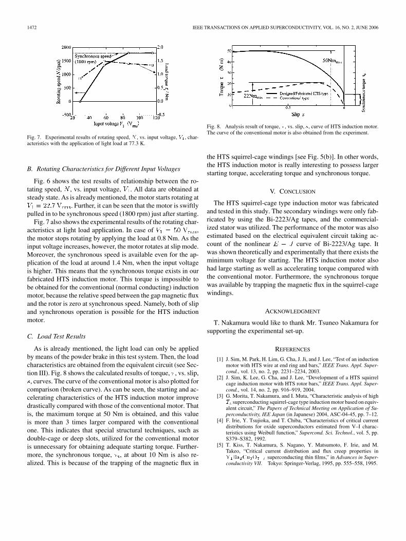
As is already mentioned, the light load can only be appliedby means of the powder brake in this test system. Then, the loadcharacteristics are obtained from the equivalent circuit (see Sec-tion III). Fig. 8 shows the calculated results of torque, , vs. slip,, curves. The curve of the conventional motor is also plotted for
comparison (broken curve). As can be seen, the starting and ac-celerating characteristics of the HTS induction motor improvedrastically compared with those of the conventional motor. Thatis, the maximum torque at 50 Nm is obtained, and this valueis more than 3 times larger compared with the conventionalone. This indicates that special structural techniques, such asdouble-cage or deep slots, utilized for the conventional motoris unnecessary for obtaining adequate starting torque. Further-more, the synchronous torque, , at about 10 Nm is also re-alized. This is because of the trapping of the magnetic flux in
Fig. 8. Analysis result of torque, � , vs. slip, s, curve of HTS induction motor.The curve of the conventional motor is also obtained from the experiment.
the HTS squirrel-cage windings [see Fig. 5(b)]. In other words,the HTS induction motor is really interesting to possess largerstarting torque, accelerating torque and synchronous torque.
V. CONCLUSION
The HTS squirrel-cage type induction motor was fabricatedand tested in this study. The secondary windings were only fab-ricated by using the Bi-2223/Ag tapes, and the commercial-ized stator was utilized. The performance of the motor was alsoestimated based on the electrical equivalent circuit taking ac-count of the nonlinear curve of Bi-2223/Ag tape. Itwas shown theoretically and experimentally that there exists theminimum voltage for starting. The HTS induction motor alsohad large starting as well as accelerating torque compared withthe conventional motor. Furthermore, the synchronous torquewas available by trapping the magnetic flux in the squirrel-cagewindings.
ACKNOWLEDGMENT
T. Nakamura would like to thank Mr. Tsuneo Nakamura forsupporting the experimental set-up.
REFERENCES
[1] J. Sim, M. Park, H. Lim, G. Cha, J. Ji, and J. Lee, “Test of an inductionmotor with HTS wire at end ring and bars,” IEEE Trans. Appl. Super-cond., vol. 13, no. 2, pp. 2231–2234, 2003.
[2] J. Sim, K. Lee, G. Cha, and J. Lee, “Development of a HTS squirrelcage induction motor with HTS rotor bars,” IEEE Trans. Appl. Super-cond., vol. 14, no. 2, pp. 916–919, 2004.
[3] G. Morita, T. Nakamura, and I. Muta, “Characteristic analysis of highT superconducting squirrel-cage type induction motor based on equiv-alent circuit,” The Papers of Technical Meeting on Application of Su-perconductivity, IEE Japan (in Japanese) 2004, ASC-04-45, pp. 7–12.
[4] F. Irie, Y. Tsujioka, and T. Chiba, “Characteristics of critical currentdistributions for oxide superconductors estimated from V–I charac-teristics using Weibull function,” Supercond. Sci. Technol., vol. 5, pp.S379–S382, 1992.
[5] T. Kiss, T. Nakamura, S. Nagano, Y. Matsumoto, F. Irie, and M.Takeo, “Critical current distribution and flux creep properties inY Ba Cu O superconducting thin films,” in Advances in Super-conductivity VII. Tokyo: Springer-Verlag, 1995, pp. 555–558, 1995.