127
Getting Started With the Tiva™ C Series TM4C123G LaunchPad Workshop Version 1.04

Getting Started With the Tiva™ C Series TM4C123G LaunchPad Workshop
Version 1.04

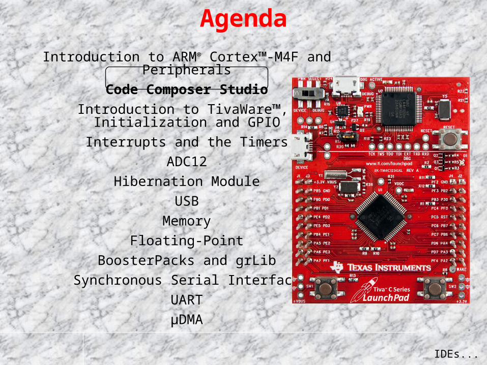
Agenda
Portfolio ...
Introduction to ARM® Cortex™-M4F and Peripherals
Code Composer Studio
Introduction to TivaWare™, Initialization and GPIO
Interrupts and the Timers
ADC12
Hibernation Module
USB
Memory
Floating-Point
BoosterPacks and grLib
Synchronous Serial Interface
UART
µDMA
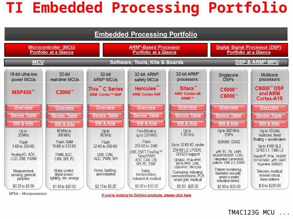
TI Embedded Processing Portfolio
TM4C123G MCU ...
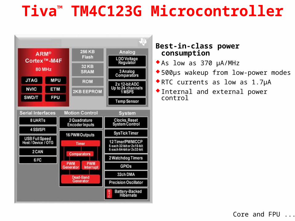
Tiva™ TM4C123G Microcontroller
Best-in-class power consumptionAs low as 370 µA/MHz500µs wakeup from low-power modes RTC currents as low as 1.7µA Internal and external power control
Core and FPU ...

M4 Core and Floating-Point Unit
32-bit ARM® Cortex™-M4 core Thumb2 16/32-bit code: 26% less memory & 25 % faster than pure 32-bit System clock frequency up to 80 MHz 100 DMIPS @ 80MHz Flexible clocking system
Internal precision oscillator External main oscillator with PLL support Internal low frequency oscillator Real-time-clock through Hibernation module
Saturated math for signal processing Atomic bit manipulation. Read-Modify-Write using bit-banding Single Cycle multiply and hardware divider Unaligned data access for more efficient memory usage IEEE754 compliant single-precision floating-point unit JTW and Serial Wire Debug debugger access
ETM (Embedded Trace Macrocell) available through Keil and IAR emulators
Memory ...

TM4C123GH6PM Memory
256KB Flash memory Single-cycle to 40MHz Pre-fetch buffer and speculative branch improves
performance above 40 MHz
32KB single-cycle SRAM with bit-banding
Internal ROM loaded with TivaWare software Peripheral Driver Library Boot Loader Advanced Encryption Standard (AES) cryptography
tables Cyclic Redundancy Check (CRC) error
detection functionality
2KB EEPROM (fast, saves board space) Wear-leveled 500K program/erase cycles 32 16-word blocks Can be bulk or block erased 10 year data retention 4 clock cycle read time
Peripherals ...
0x00000000 Flash
0x01000000 ROM
0x20000000 SRAM
0x22000000 Bit-banded SRAM
0x40000000 Peripherals & EEPROM
0x42000000 Bit-banded Peripherals
0xE0000000 Instrumentation, ETM, etc.

TM4C123GH6PM Peripherals
Battery-backed Hibernation Module Internal and external power control (through external voltage regulator) Separate real-time clock (RTC) and power source VDD3ON mode retains GPIO states and settings Wake on RTC or Wake pin 16 32-bit words of battery backed memory 5 µA Hibernate current with GPIO retention. 1.7 µA without
Serial Connectivity USB 2.0 (OTG/Host/Device) 8 - UART with IrDA, 9-bit and ISO7816 support 6 - I2C 4 - SPI, Microwire or TI synchronous serial interfaces 2 - CAN
More ...

TM4C123GH6PM Peripherals
Two 1MSPS 12-bit SAR ADCs Twelve shared inputs Single ended and differential measurement Internal temperature sensor 4 programmable sample sequencers Flexible trigger control: SW, Timers, Analog comparators, GPIO VDDA/GNDA voltage reference Optional hardware averaging 2 analog and 16 digital comparators µDMA enabled
0 - 43 GPIO Any GPIO can be an external edge or level triggered
interrupt Can initiate an ADC sample sequence or µDMA transfer
directly Toggle rate up to the CPU clock speed on the Advanced
High-Performance Bus 5-V-tolerant in input configuration Programmable Drive Strength (2, 4, 8 mA or 8 mA
with slew rate control) Programmable weak pull-up, pull-down, and open drain
More ...

TM4C123GH6PM PeripheralsMemory Protection Unit (MPU)
Generates a Memory Management Fault on incorrect access to region
Timers 2 Watchdog timers with separate clocks SysTick timer. 24-bit high speed RTOS and other timer Six 32-bit and Six 64-bit general purpose timers PWM and CCP modes Daisy chaining User enabled stalling on CPU Halt flag from debugger for all timers
32 channel µDMA Basic, Ping-pong and scatter-gather modes Two priority levels 8,16 and 32-bit data sizes Interrupt enabled
More...

TM4C123GH6PM PeripheralsNested-Vectored Interrupt Controller (NVIC)
7 exceptions and 71 interrupts with 8 programmable priority levels Tail-chaining Deterministic: always 12 cycles or 6 with tail-chaining Automatic system save and restore
Two Motion Control modules. Each with: 8 high-resolution PWM outputs (4 pairs) H-bridge dead-band generators and hardware polarity control Fault input for low-latency shutdown Quadrature Encoder Inputs (QEI) Synchronization in and between the modules
Board...

Tiva™ EK-TM4C123GXL LaunchPad
ARM® Cortex™-M4F 64-pin 80MHz TM4C123GH6PM
On-board USB ICDI (In-Circuit Debug Interface)
Micro AB USB port Device/ICDI power switch BoosterPack XL pinout also supports
existing BoosterPacks 2 user pushbuttons Reset button 3 user LEDs (1 tri-color device) Current measurement test points 16MHz Main Oscillator crystal 32kHz Real Time Clock crystal 3.3V regulator Support for multiple IDEs:
Lab...

Lab 1: Hardware and Software Setup
Install the software Review the kit contents Connect the hardware Test the QuickStart application
USB Emulation Connection
Agenda ...
Agenda
IDEs...
Introduction to ARM® Cortex™-M4F and Peripherals
Code Composer Studio
Introduction to TivaWare™, Initialization and GPIO
Interrupts and the Timers
ADC12
Hibernation Module
USB
Memory
Floating-Point
BoosterPacks and grLib
Synchronous Serial Interface
UART
µDMA

Development Tools for Tiva C Series MCUs
Eval Kit License
30-day full function.
Upgradeable
32KB code size limited.
Upgradeable
32KB code size limited.
Upgradeable
Full function. Onboard
emulation limited
Compiler GNU C/C++ IAR C/C++ RealView C/C++ TI C/C++
Debugger / IDE gdb / Eclipse
C-SPY / Embedded Workbench
µVision CCS/Eclipse-based suite
Full Upgrade
99 USD personal edition /
2800 USD full support
2700 USDMDK-Basic (256
KB) = €2000 (2895 USD)
445 USD
JTAG Debugger J-Link, 299
USD U-Link, 199 USD XDS100, 79 USD
TI SW Ecosystem …

• High-level OS support andTI-RTOS
• OS Independent support and TI-Wares software packages
Run-Time Software Development Tools
• TI Design Network: off-the-shelf software, tools and services
• Forums & Wikis
• In-person and online training
Support & Community
• CCStudio™ Integrated Development Environment (IDE) and other IDEs
• Optimizing compilers
• Design Kits & Evaluation Modules
TI Software and Tools Ecosystem
Run-Time Software …

TI Wares: minimizes programming complexity w/ optimized drivers & OS independent support for TI solutions
• Low-level driver libraries• Peripheral programming interface • Tool-chain agnostic C code• Available today
TI-RTOS: provides an optimized real-time kernel at no charge that works with TI
Wares • Real-time kernel (SYSBIOS) + optimized
for TI devices:• Scheduling
• Memory management
• Utilities• Foundational software packages (TI
Wares)• Libraries and examples• TI RTOS available today
SYSBIOS + TI Wares
SDKSoftware Development Kit
TI-RTOS
+• File systems• Network stack• USB
Run-Time Software
CCS Functional Overview …
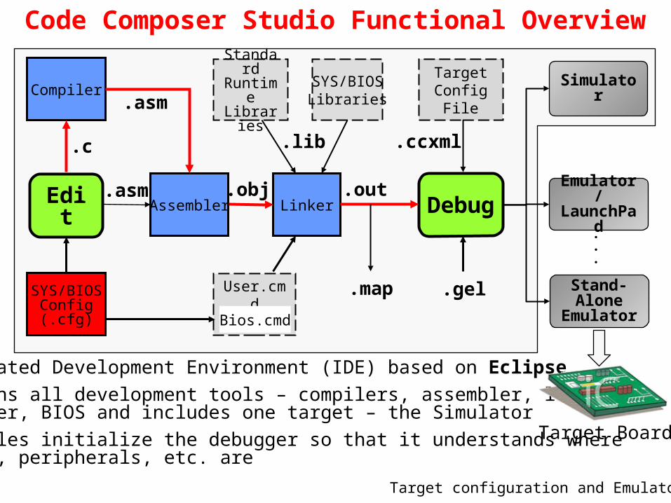
Code Composer Studio Functional Overview
Compiler
Assembler Linker
.c
.asm .obj
.asm
Edit Debug
Simulator
Emulator/ LaunchPad
TargetConfig
File
Integrated Development Environment (IDE) based on Eclipse Contains all development tools – compilers, assembler, linker,
debugger, BIOS and includes one target – the Simulator GEL files initialize the debugger so that it understands where
memory, peripherals, etc. are
Standard Runtime Libraries
.lib
.mapUser.cmd
SYS/BIOSLibraries
SYS/BIOSConfig(.cfg) Bios.cmd
.out
.ccxml
Stand-AloneEmulator
Target Board
.
.
.
.gel
Target configuration and Emulators…

Target Configuration and Emulators The Target Configuration File specifies:
• Connection to the target (Simulator or Emulator type)• Target device • GEL file (if applicable) for hardware setup
Emulator (Connection) Options• Built-in and external emulators from TI, Blackhawk,
Spectrum Digital and others• XDS100v1/v2, 200, 510, 560, 560v2
Projects and Workspaces …

Projects and Workspaces (viewed in CCS)
WORKSPACE
PROJECTSource
Projects and Workspaces …

Projects and Workspaces
PROJECT folder contains:• Build and tool settings (for use
in managed MAKE projects)• Files can be linked to or
reside in the project folder• Deleting a linked file within the
Project Explorer only deletes the link
Workspace• Project 1• Project 2• Project 3• Settings/preferences
Project• Source Files• Header Files• Library Files• Build/tool settings
Source Files• Code and Data
Header Files• Declarations
Library Files• Code and Data
Link
Link
Link
Link
WORKSPACE folder contains:• IDE settings and preferences• Projects can reside in the workspace
folder or be linked from elsewhere• When importing projects into the
workspace, linking is recommended• Deleting a project within the Project
Explorer only deletes the link
Creating a New Project …
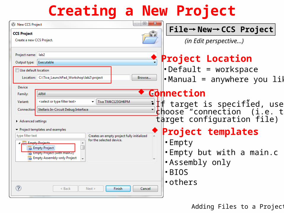
Creating a New ProjectFile New CCS Project
(in Edit perspective…)
Project Location• Default = workspace• Manual = anywhere you like
Project templates• Empty• Empty but with a main.c• Assembly only• BIOS• others
Connection• If target is specified, user can
choose “connection” (i.e. thetarget configuration file)
Adding Files to a Project …

Adding Files to a Project Users can ADD (copy or link) files into their project
• SOURCE files are typically COPIED• LIBRARY files are typically LINKED (referenced)
1 Right-click on project and select: 2 Select file(s) to add to the project:
3 Select “Copy” or “Link” COPY• Copies file from original location
to project folder (two copies)
LINK• References (points to) source
file in the original folder• Can select a “reference” point –
typically PROJECT_LOC
Making a Project Portable …

Portable Projects Why make your projects “portable”?
• Simplifies project sharing • You can easily re-locate your projects• Allow simple changes to link to new releases of software libraries
Copied files are not a problem (theymove with the project folder)Linked files may be an issue. Theyare located outside the project folder via a:
• absolute path, or• relative path
This is the Path Variable for a relative path. This can be specified for every linked file.
Path and Build Variables …

Path Variables and Build Variables Path Variables
• Used by CCS (Eclipse) to store the base path for relative linked files • Example: PROJECT_LOC is set to the path of your project, say
c:/Tiva_LaunchPad_Workshop/lab2/project
• Used as a reference point for relative paths, e.g.${PROJECT_LOC}/../files/main.c
Build Variables• Used by CCS (Eclipse) to store base path for build libraries or files • Example: CG_TOOL_ROOT is set to the path for the code
generation tools (compiler/linker)• Used to find #include .h files, or object libraries, e.g.
${CG_TOOL_ROOT}/include or ${CG_TOOL_ROOT}/lib
How are these variables defined?• The variables in these examples are automatically defined
when you create a new project (PROJECT_LOC) and when youinstall CCS with the build tools (CG_TOOL_ROOT)
• What about TivaWare or additional software libraries? You can definesome new variables yourself
Adding Variables …

Adding Variables Why are we doing this?
• We could use PROJECT_LOC for all linked resources or PROJECT_ROOT asthe base for build variables
• It is “almost” portable, BUT if you move or copy your project, you haveto put it at the same “level” in the file system
• Defining a link and build variable for TivaWare location gives us a relativepath that does NOT depend on location of the project (much more portable)
• Also, if we install a new version of TivaWare, we only need to change thesevariables – which is much easier than creating new relative links
How to add Path and Build Variables• Project Properties, expand the Resource category, click on
Linked Resources. You will see a tab for Path Variables, click Newto add a new path variable
• Project Properties, click on Build category, click on the Variables tab,Click New to add a new build variable
• In the lab, we’ll add a path variable and build variable TIVAWARE_INSTALLto be the path of the latest TivaWare release
Note:• This method defines the variables as part of the project (finer control)• You can also define variables as part of your workspace (do it once)
Build Configurations …

Build Configurations Code Composer has two pre-defined BUILD CONFIGURATIONS:
• Debug (symbols, no optimization) – great for LOGICAL debug• Release (no symbols, optimization) – great for PERFORMANCE
Users can create their own custom build configurations• Right-click on the project and select Properties• Then click “Processor Options” or any other category:
CCS Licensing and Pricing …

CCSv5 Licensing and Pricing Licensing
• Wide variety of options (node locked, floating, time based)• All versions (full, DSK, free tools) use the same image• Updates readily available online
Pricing• Includes FREE options noted below• Annual subscription - $99 ($159 for floating license)
* recommended option: purchase Development Kit, use XDS100v1-2, & Free CCSv5
** $495 includes DVD, $445 is download only
Item Description Price AnnualPlatinum Eval Tools Full tools with 90 day limit (all EMU) FREE
Platinum Bundle XDS100 use (EVM or simulator) FREE *Platinum Node Lock Full tools tied to a machine $495/$445 ** $99
Platinum Floating Full tools shared across machines $795 $159
MSP430 Code-Limited MSP430 (16KB code limit) FREE
CCS FYI …
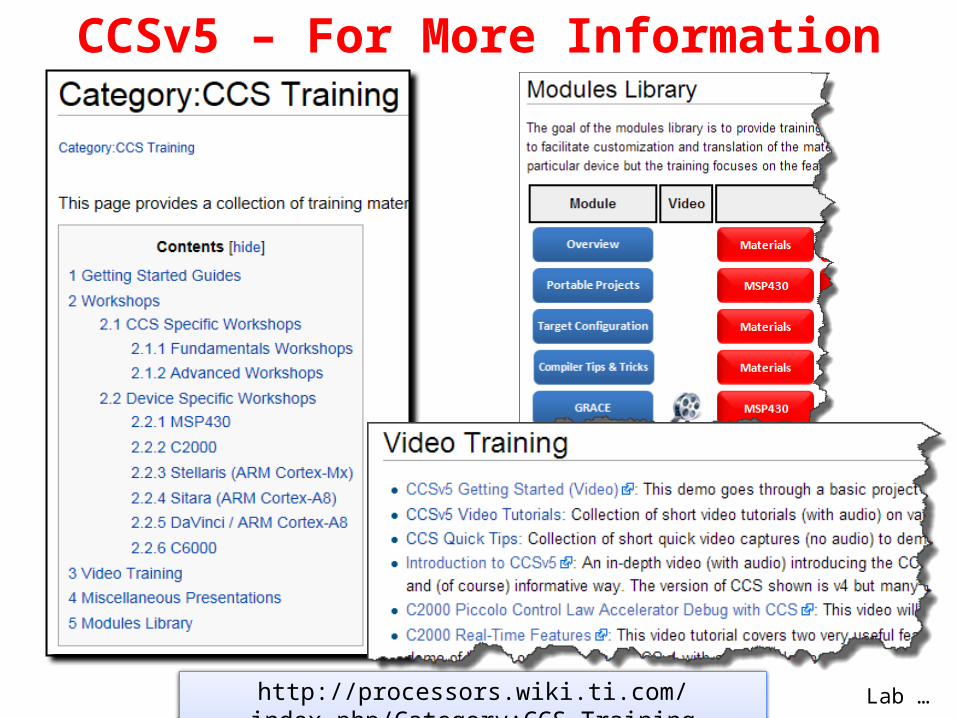
CCSv5 – For More Information
http://processors.wiki.ti.com/index.php/Category:CCS_Training Lab …

Lab 2: Code Composer Studio
Create a new project Experiment with some CCS features Use the LM Flash Programmer
Agenda ...
USB Emulation Connection

Agenda
TivaWare...
Introduction to ARM® Cortex™-M4F and Peripherals
Code Composer Studio
Introduction to TivaWare™, Initialization and GPIO
Interrupts and the Timers
ADC12
Hibernation Module
USB
Memory
Floating-Point
BoosterPacks and grLib
Synchronous Serial Interface
UART
µDMA

Peripheral Driver Library High-level API interface to complete peripheral set License & royalty free use for TI Cortex-M parts Available as object library and as source code Programmed into the on-chip ROM
TivaWare™ for C Series Features
Graphics Library Graphics primitive and widgets 153 fonts plus Asian and Cyrillic Graphics utility tools
USB Stacks and Examples USB Device and Embedded Host compliant Device, Host, OTG and Windows-side examples Free VID/PID sharing program
Ethernet lwip and uip stacks with 1588 PTP modifications Extensive examples
Extras Wireless protocols IQ math examples Bootloaders Windows side applications
ISP Options...
Sensor Library An interrupt driven I2C master driver for handling
I2C transfers A set of drivers for I2C connected sensors A set of routines for common sensor operations Three layers: Transport, Sensor and Processing

In System Programming Options
Tiva Serial Flash Loader Small piece of code that allows programming of the flash without the need for a
debugger interface. All Tiva C Series MCUs ship with the loader in flash UART or SSI interface option The LM Flash Programmer interfaces with the serial flash loader See application note SPMA029
Tiva Boot Loader Preloaded in ROM or can be programmed at the beginning of flash to act as an
application loader Can also be used as an update mechanism for an application running on a Tiva
microcontroller. Interface via UART (default), I2C, SSI, Ethernet, USB (DFU H/D) Included in the Tiva Peripheral Driver Library with full applications examples
Fundamental Clocks...

Fundamental Clock Sources
Precision Internal Oscillator (PIOSC) 16 MHz ± 3%
Main Oscillator (MOSC) using… An external single-ended clock source An external crystal
Internal 30 kHz Oscillator 30 kHz ± 50% Intended for use during Deep-Sleep power-saving modes
Hibernation Module Clock Source 32,768Hz crystal Intended to provide the system with a real-time clock source
SysClk Sources...

System (CPU) Clock SourcesThe CPU can be driven by any of the fundamental clocks … Internal 16 MHz Main Internal 30 kHz External Real-Time
- Plus - The internal PLL (400 MHz) The internal 16MHz oscillator divided by four (4MHz ± 3%)
Clock Source Drive PLL? Used as SysClk?Internal 16MHz Yes YesInternal 16Mhz/4 No YesMain Oscillator Yes YesInternal 30 kHz No YesHibernation Module No YesPLL - Yes
Clock Tree...

Tiva C Series Clock Tree
driverLib API SysCtlClockSet() selects: SYSDIV divider setting OSC or PLL Main or Internal oscillator Crystal frequency GPIO...

General Purpose IO
Any GPIO can be an interrupt: Edge-triggered on rising, falling or both Level-sensitive on high or low values
Can directly initiate an ADC sample sequence or µDMA transfer Toggle rate up to the CPU clock speed on the Advanced
High-Performance Bus. ½ CPU clock speed on the Standard. 5V tolerant in input configuration Programmable Drive Strength (2, 4, 8mA or 8mA with slew rate
control) Programmable weak pull-up, pull-down, and open drain Pin state can be retained during Hibernation mode
Pin Mux Utility...

Pin Mux Utility
Masking...
Allows the user to graphically configure the device pin-out Generates source and header files for use with any of the supported IDE’s
http://www.ti.com/tool/tm4c_pinmux
0 0 1 0 0 1 1 0 0 0000…
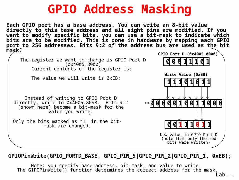
GPIO Address Masking
The register we want to change is GPIO Port D (0x4005.8000)Current contents of the register is: 0 0 0 1 1 1 0 1
Instead of writing to GPIO Port D directly, write to 0x4005.8098. Bits 9:2 (shown here) become a bit-mask
for the value you write.
0 0 1 1 1 0 1 1
1 1 1 0 1 0 1 1
Only the bits marked as “1” in the bit-mask are changed.
GPIO Port D (0x4005.8000)
The value we will write is 0xEB:Write Value (0xEB)
New value in GPIO Port D (note that only the red bits were written)
Each GPIO port has a base address. You can write an 8-bit value directly to this base address and all eight pins are modified. If you want to modify specific bits, you can use a bit-mask to indicate which bits are to be modified. This is done in hardware by mapping each GPIO port to 256 addresses. Bits 9:2 of the address bus are used as the bit mask.
GPIOPinWrite(GPIO_PORTD_BASE, GPIO_PIN_5|GPIO_PIN_2|GPIO_PIN_1, 0xEB);
Note: you specify base address, bit mask, and value to write. The GIPOPinWrite() function determines the correct address for the mask.
Lab...

Lab 3: Initialization and GPIO
Configure the system clock Enable and configure GPIO Use a software delay to toggle an LED
on the evaluation board
Agenda ...
USB Emulation Connection

Agenda
NVIC...
Introduction to ARM® Cortex™-M4F and Peripherals
Code Composer Studio
Introduction to TivaWare™, Initialization and GPIO
Interrupts and the Timers
ADC12
Hibernation Module
USB
Memory
Floating-Point
BoosterPacks and grLib
Synchronous Serial Interface
UART
µDMA

Nested Vectored Interrupt Controller (NVIC)
Handles exceptions and interrupts 8 programmable priority levels, priority grouping 7 exceptions and 71 Interrupts Automatic state saving and restoring Automatic reading of the vector table entry Pre-emptive/Nested Interrupts Tail-chaining Deterministic: always 12 cycles or 6 with tail-chaining
t
Motor control ISRs (e.g. PWM, ADC)
Communication ISRs (e.g. CAN)
Main application (foreground)
Tail Chaining...

PUSH POPISR 1 POP ISR 2
PUSH ISR 1 POPISR 2
12Cycles
IRQ1
IRQ2
Typical processor
Cortex-M4Interrupt handling in
HW 6Cycles
12Cycles
Interrupt Latency - Tail Chaining
HighestPriority
Tail-chaining
Pre-emption …
PUSH

Interrupt Latency – Pre-emption
ISR 1 ISR 2
ISR 1 POP ISR 2
1-12
Cycles
IRQ1
IRQ2
Cortex-M4
6Cycles
HighestPriority
POP
12Cycles
Typical processor
Late arrival...
PUSHPOP POP

ISR 2
Interrupt Latency – Late Arrival
IRQ1
IRQ2
ISR 2ISR 1
PUSH POPCortex-M4
HighestPriority
12Cycles
6Cycles
ISR 1
Typical processor
Interrupt handling...
PUSH POPPUSH PUSH POP

Interrupt handling is automatic. No instruction overhead.
Entry Automatically pushes registers R0–R3, R12, LR, PSR, and PC onto the
stack In parallel, ISR is pre-fetched on the instruction bus. ISR ready to start
executing as soon as stack PUSH complete
Exit Processor state is automatically restored from the stack In parallel, interrupted instruction is pre-fetched ready for execution
upon completion of stack POP
Exception types...
Cortex-M4® Interrupt Handling

Cortex-M4® Exception Types
VectorNumber
Exception Type
Priority Vector address
Descriptions
1 Reset -3 0x04 Reset
2 NMI -2 0x08 Non-Maskable Interrupt
3 Hard Fault -1 0x0C Error during exception processing
4 Memory Management Fault
Programmable 0x10 MPU violation
5 Bus Fault Programmable 0x14 Bus error (Prefetch or data abort)
6 Usage Fault Programmable 0x18 Exceptions due to program errors
7-10 Reserved - 0x1C - 0x28
11 SVCall Programmable 0x2C SVC instruction
12 Debug Monitor Programmable 0x30 Exception for debug
13 Reserved - 0x34
14 PendSV Programmable 0x38
15 SysTick Programmable 0x3C System Tick Timer
16 and above Interrupts Programmable 0x40 External interrupts (Peripherals)
Vector Table...

Cortex-M4® Vector Table
After reset, vector table is located at address 0
Each entry contains the address of the function to be executed
The value in address 0x00 is used as starting address of the Main Stack Pointer (MSP)
Vector table can be relocated by writing to the VTABLE register (must be aligned on a 1KB boundary)
Open startup_ccs.c to see vector table coding
GPTM...

General Purpose Timer Module
Six 16/32-bit and Six 32/64-bit general purpose timers Twelve 16/32-bit and Twelve 32/64-bit capture/compare/PWM pins
Timer modes:• One-shot• Periodic• Input edge count or time capture with 16-bit prescaler• PWM generation (separated only)• Real-Time Clock (concatenated only)
Count up or down
Simple PWM (no deadband generation)
Support for timer synchronization, daisy-chains, and stalling during debugging
May trigger ADC samples or DMA transfers
Lab...

Lab 4: Interrupts and the GP Timer
Enable and configure the Timer Enable and configure Interrupts Write the ISR code and test Generate an exception
Agenda ...
USB Emulation Connection

Agenda
ADC...
Introduction to ARM® Cortex™-M4F and Peripherals
Code Composer Studio
Introduction to TivaWare™, Initialization and GPIO
Interrupts and the Timers
ADC12
Hibernation Module
USB
Memory
Floating-Point
BoosterPacks and grLib
Synchronous Serial Interface
UART
µDMA

Analog-to-Digital Converter
Tiva TM4C MCUs feature two ADC modules (ADC0 and ADC1) that can be used to convert continuous analog voltages to discrete digital values
Each ADC module has 12-bit resolution Each ADC module operates independently
and can:• Execute different sample sequences• Sample any of the shared analog input
channels• Generate interrupts & triggers
ADC
VIN VOUT
Input Channels
Triggers
Interrupts/ Triggers
Interrupts/ Triggers
12
VIN
VO
UT
000
001
011
010
100
101
t
t
ADC1
ADC0
Features...

TM4C123GH6PM ADC Features
Two 12-bit 1MSPS ADCs 12 shared analog input channels Single ended & differential input
configurations On-chip temperature sensor Maximum sample rate of one million
samples/second (1MSPS). Fixed references (VDDA/GNDA) due to
pin-count limitations 4 programmable sample conversion
sequencers per ADC Separate analog power & ground pins
Flexible trigger control• Controller/ software• Timers• Analog comparators• GPIO
2x to 64x hardware averaging 8 Digital comparators / per ADC 2 Analog comparators Optional phase shift in sample time,
between ADC modules … programmable from 22.5 ° to 337.5°
ADC
VIN VOUT
Sequencers...

ADC Sample Sequencers
Tiva TM4C ADC’s collect and sample data using programmable sequencers. Each sample sequence is a fully programmable series of consecutive (back-to-back)
samples that allows the ADC module to collect data from multiple input sources without having to be re-configured.
Each ADC module has 4 sample sequencers that control sampling and data capture. All sample sequencers are identical except for the number of samples they can capture
and the depth of their FIFO. To configure a sample sequencer, the following information is required:
• Input source for each sample• Mode (single-ended, or differential) for each sample• Interrupt generation on sample completion for each sample• Indicator for the last sample in the sequence
Each sample sequencer can transfer data independently through a dedicated μDMA channel. Sequencer Number of
Samples Depth of FIFO
SS 3 1 1SS 2 4 4SS 1 4 4SS 0 8 8
Lab...
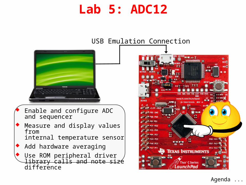
Lab 5: ADC12
Enable and configure ADC and sequencer
Measure and display values from internal temperature sensor
Add hardware averaging Use ROM peripheral driver library
calls and note size difference
Agenda ...
USB Emulation Connection

Agenda
Key Features...
Introduction to ARM® Cortex™-M4F and Peripherals
Code Composer Studio
Introduction to TivaWare™, Initialization and GPIO
Interrupts and the Timers
ADC12
Hibernation Module
USB
Memory
Floating-Point
BoosterPacks and grLib
Synchronous Serial Interface
UART
µDMA

Key Features
Real Time Clock is a 32-bit seconds counter with a 15-bit sub seconds counter & add-in trim capability
Dedicated pin for waking using an external signal
RTC operational and hibernation memory valid as long as VBAT is valid
GPIO pins state retention provided during VDD3ON mode
Two mechanisms for power control• System Power Control for CPU
and other on-board hardware• On-chip Power Control for CPU
only
Low-battery detection, signaling, and interrupt generation, with optional wake on low battery
32,768 Hz external crystal or an external oscillator clock source
16 32-bit words of battery-backed memory are provided for you to save the processor state to during hibernation
Programmable interrupts for RTC match, external wake, and low battery events.
Low Power Modes...

Power Modes
Run mode Sleep mode stops the
processor clock• 2 SysClk wakeup time
Deep Sleep mode stops the system clock and switches off the PLL and Flash
• 1.25 – 350 µS wakeup time Hibernate mode with only
hibernate module powered (VDD3ON, RTC and no RTC)
• ~500µS wakeup timeTBD
Power Mode Comparison...
1.05

Power Mode ComparisonMode →
Run Mode Sleep Mode Deep Sleep Mode
Hibernation (VDD3ON)
Hibernation (RTC)
Hibernation (no RTC)
Parameter ↓
IDD 32 mA 10 mA 1.05 mA 5 μA 1.7 μA 1.6 μA
VDD 3.3 V 3.3 V 3.3 V 3.3 V 0 V 0 V
VBAT N.A. N.A. N.A. 3 V 3 V 3 V
System Clock 40 MHz with PLL40 MHz with PLL 30 kHz Off Off Off
CorePowered On Powered On Powered On Off Off Off
Clocked Not Clocked Not Clocked Not Clocked Not Clocked Not Clocked
Peripherals All On All Off All Off All Off All Off All Off
Code while{1} N.A. N.A. N.A. N.A. N.A.
LaunchPad Considerations ...Box denotes power modes available on LaunchPad board

LaunchPad Considerations
The low-cost LaunchPad board does not have a battery holder VDD and VBAT are wired together on the board
(this disables battery-only powered low-power modes) Device current is measured between test points H24 and H25
Lab ...

Lab 6: Low Power Modes
Place device in low power modes Wake from pin Wake from RTC Measure current No battery holder on board
Agenda ...
USB Emulation Connection PowerMeasurement
Jumper

Agenda
USB Basics...
Introduction to ARM® Cortex™-M4F and Peripherals
Code Composer Studio
Introduction to TivaWare™, Initialization and GPIO
Interrupts and the Timers
ADC12
Hibernation Module
USB
Memory
Floating-Point
BoosterPacks and grLib
Synchronous Serial Interface
UART
µDMA

USB Basics
Multiple connector sizes
4 pins – power, ground and 2 data lines(5th pin ID for USB 2.0 connectors)
Configuration connects power 1st, then data
Standards: USB 1.1
• Defines Host (master) and Device (slave)• Speeds to 12Mbits/sec• Devices can consume 500mA (100mA for startup)
USB 2.0• Speeds to 480Mbits/sec• OTG addendum
USB 3.0• Speeds to 4.8Gbits/sec• New connector(s)• Separate transmit/receive data lines
USB Basics...

USB Basics
USB Device … most USB products are slaves
USB Host … usually a PC, but can be embedded
USB OTG … On-The-Go Dynamic switching between host and device roles Two connected OTG ports undergo host negotiation
Host polls each Device at power up. Information from Deviceincludes:
Device Descriptor (Manufacturer & Product ID so Host can find driver)
Configuration Descriptor (Power consumption and Interface descriptors)
Endpoint Descriptors (Transfer type, speed, etc) Process is called Enumeration … allows Plug-and-Play
TM4C123GH6PM USB...

TM4C123GH6PM USB USB 2.0 full speed (12 Mbps) and low speed (1.5 Mbps)
operation On-the-go (OTG), Host and Device functions Integrated PHY Transfer types: Control, Interrupt, Bulk and Isochronous Device Firmware Update (DFU) device in ROM
Tiva collaterals Texas Instruments is a member of the
USB Implementers Forum. Tiva is approved to use the
USB logo Vendor/Product ID sharing
http://www.ti.com/lit/pdf/spml001
FREE Vendor ID/ Product ID
sharing program
FREE Vendor ID/ Product ID
sharing program
Block Diagram...

USB Peripheral Block Diagram
Integrated USB Controller and PHY with up to 16 Endpoints 1 dedicated control IN endpoint and 1 dedicated control OUT endpoint Up to 7 configurable IN endpoints and 7 configurable OUT endpoints 4 KB dedicated endpoint memory (not part of device SRAM) Separate DMA channels (up to three IN Endpoints and three OUT Endpoints) 1 endpoint may be defined for double-buffered 1023-bytes isochronous packet size
EP0 – 15Control
USBLib...

TivaWare™ USBLib
License-free & royalty-free drivers, stack and example applications for Tiva MCUs
USBLib supports Host/Device and OTG Builds on DriverLib API
• Adds framework for generic Host and Device functionality
• Includes implementations of common USB classes Layered structure Drivers and .inf files included where appropriate Tiva MCUs have passed USB Device and
Embedded Host compliance testing
• Device Examples• HID Keyboard• HID Mouse• CDC Serial• Mass Storage• Generic Bulk• Audio• Device Firmware Upgrade• Oscilloscope
• Windows INF for supported devices
• Points to base Windows drivers
• Sets config string• Sets PID/VID• Precompiled DLL saves
development time• Device framework integrated into
USBLib
Abstraction Levels...

USB DriverLib API
USB Host Controller API/USB Device API
Host Class Driver/Device Class Driver APIs
Host Class/ Device Class APIs
Application 4
Implements its own USB
protocol using Driverlib.
(Third party USB stack)
Application 3
Uses existing API for generic
host/device operation.
Uses DriverLib for features not
covered by these APIs.
(Custom Classes)
Application 2
Passes key info to the Driver API.
Driver API handles all lower level
functions for the chosen class.
(Custom HID device)
Application 1
Passes simplified data to a higher
level API.
(Custom HID mouse)
USB API Abstraction Levels
Level of customization
Lev
el o
f a
bstr
act
ion
LOW HIGH
HIGH
LOW
Lab...

Lab 7: USB
Run usb_bulk_example code and windows side app
Inspect stack setup Observe data on device
Agenda ...
USB DeviceConnection
USB Emulation Connection

Agenda
Memory Control...
Introduction to ARM® Cortex™-M4F and Peripherals
Code Composer Studio
Introduction to TivaWare™, Initialization and GPIO
Interrupts and the Timers
ADC12
Hibernation Module
USB
Memory
Floating-Point
BoosterPacks and grLib
Synchronous Serial Interface
UART
µDMA

Flash, SRAM and ROM Control
Memory Blocks and Control Logic for: SRAM ROM Flash
EEPROM Control...

EEPROM Control
EEPROM Block and Control Logic EEPROM block is connected to the
AHB (Advanced High Performance Bus)
Flash Features...

Flash 256KB / 40MHz starting at 0x00000000 Organized in 1KB independently erasable blocks Code fetches and data access occur over separate buses Below 40MHz, Flash access is single cycle Above 40MHz, the prefetch buffer fetches two 32-bit words/cycle.
No wait states for sequential code. Branch speculation avoids wait state on some branches Programmable write and execution protection available Simple programming interface
0x00000000 Flash
0x01000000 ROM
0x20000000 SRAM
0x22000000 Bit-banded SRAM
0x40000000 Peripherals & EEPROM
0x42000000 Bit-banded Peripherals
0xE0000000 Instrumentation, ETM, etc. EEPROM...

EEPROM 2KB of memory starting at 0x400AF000 in Peripheral space Accessible as 512 32-bit words 32 blocks of 16 words (64 bytes) with access protection per block Built-in wear leveling with endurance of 500K writes Lock protection option for the whole peripheral as well as per
block using 32-bit to 96-bit codes Interrupt support for write completion to avoid polling Random and sequential read/write access (4 cycles max/word)
0x00000000 Flash
0x01000000 ROM
0x20000000 SRAM
0x22000000 Bit-banded SRAM
0x40000000 Peripherals & EEPROM
0x42000000 Bit-banded Peripherals
0xE0000000 Instrumentation, ETM, etc. SRAM...
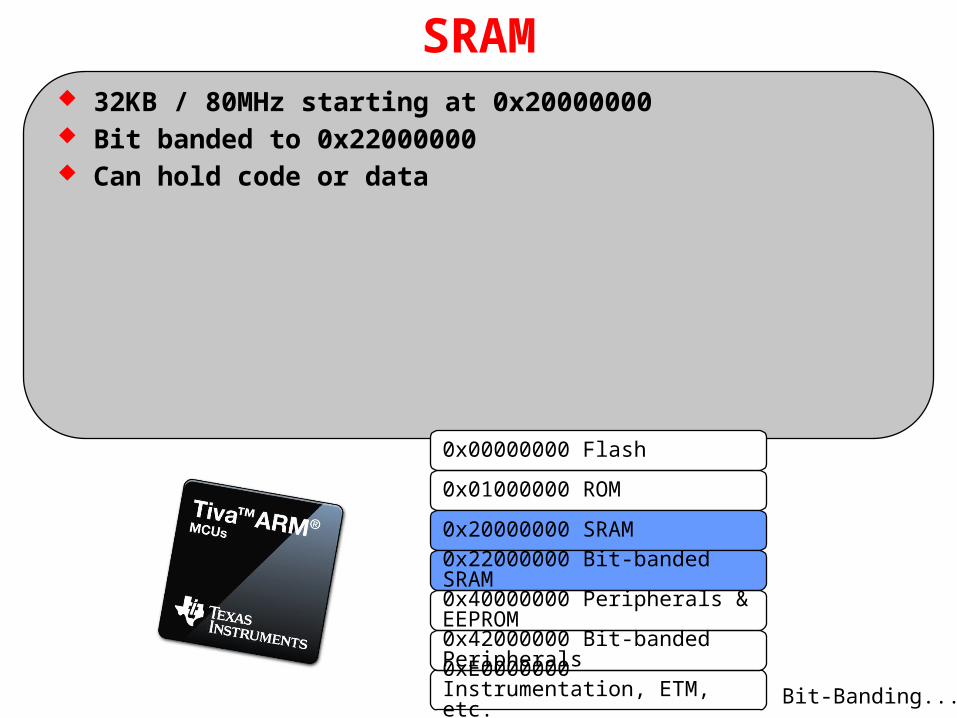
SRAM 32KB / 80MHz starting at 0x20000000 Bit banded to 0x22000000 Can hold code or data
0x00000000 Flash
0x01000000 ROM
0x20000000 SRAM
0x22000000 Bit-banded SRAM
0x40000000 Peripherals & EEPROM
0x42000000 Bit-banded Peripherals
0xE0000000 Instrumentation, ETM, etc. Bit-Banding...
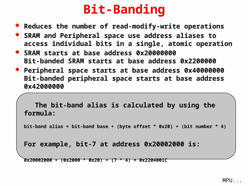
Bit-Banding Reduces the number of read-modify-write operations SRAM and Peripheral space use address aliases to access
individual bits in a single, atomic operation SRAM starts at base address 0x20000000
Bit-banded SRAM starts at base address 0x2200000 Peripheral space starts at base address 0x40000000
Bit-banded peripheral space starts at base address 0x42000000
The bit-band alias is calculated by using the formula:
bit-band alias = bit-band base + (byte offset * 0x20) + (bit number * 4)
For example, bit-7 at address 0x20002000 is:
0x20002000 + (0x2000 * 0x20) + (7 * 4) = 0x2204001C
MPU...

Memory Protection Unit (MPU) Defines 8 separate memory regions plus a background region
accessible only from privileged mode Regions of 256 bytes or more are divided into 8 equal-sized
sub-regions MPU definitions for all regions include:
• Location• Size• Access permissions• Memory attributes
Accessing a prohibited region causes a memory management fault
Privilege Levels...

Cortex M4 Privilege Levels Privilege levels offer additional protection for software,
particularly operating systems
Unprivileged : software has …• Limited access to the Priority Mask register• No access to the system timer, NVIC, or system control block• Possibly restricted access to memory or peripherals (FPU, MPU, etc)
Privileged: software has …• use of all the instructions and has access to all resources
ISRs operate in privileged mode Thread code operates in unprivileged mode unless the level is
changed via the Thread Mode Privilege Level (TMPL) bit in the CONTROL register
Lab...
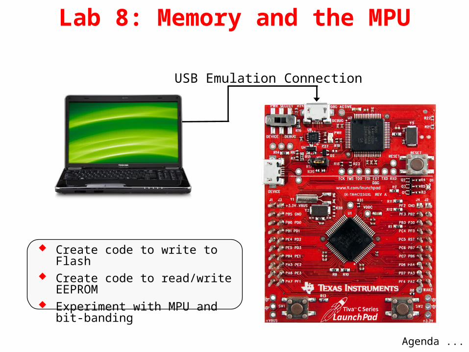
Lab 8: Memory and the MPU
Create code to write to Flash Create code to read/write EEPROM Experiment with MPU and
bit-banding
Agenda ...
USB Emulation Connection

Agenda
What is Floating-Point?...
Introduction to ARM® Cortex™-M4F and Peripherals
Code Composer Studio
Introduction to TivaWare™, Initialization and GPIO
Interrupts and the Timers
ADC12
Hibernation Module
USB
Memory
Floating-Point
BoosterPacks and grLib
Synchronous Serial Interface
UART
µDMA

What is Floating-Point?
Floating-point is a way to represent real numbers on computers
IEEE floating-point formats:
Half (16-bit)
Single (32-bit)
Double (64-bit)
Quadruple (128-bit)
What is IEEE-754?...

What is IEEE-754?
FPU...
exponent = [10000110]2 = [134]10 fraction = [0.110100001000000000000000]2 = [0.814453]10 sign = (-1)0
= [1]10
Decimal Value= (-1)s x (1+f) x 2e-bias
= [1]10 x ([1]10 + [0.814453]10) x [2134-127]10
= [1. 814453]10 x 128
= [232.249]10
Symbol s e fExample 0 1 0 0 0 0 1 1 0 1 1 0 1 0 0 0 0 1 0 0 0 0 0 0 0 0 0 0 0 0 0 0 X
Bit 31 30 29 28 27 26 25 24 23 22 21 20 19 18 17 16 15 14 13 12 11 10 9 8 7 6 5 4 3 2 1 0 XSymbol Sign (s) Exponent (e) Fraction (f)
8 bits 23 bits1 bit
Decimal Value = (-1)s (1+f) 2e-bias
where: f = ∑[(b-i)2-i] i ϵ (1,23)∀
bias = 127 for single precision floating-point

Floating-Point Unit (FPU)
The FPU provides floating-point computation functionality that is compliant with the IEEE 754 standard
Enables conversions between fixed-point and floating-point data formats, and floating-point constant instructions
The Cortex-M4F FPU fully supports single-precision:
Add Subtract Multiply Divide Single cycle multiply and accumulate (MAC) Square root
Modes of Operation...

Modes of Operation
There are three different modes of operation for the FPU:
Full-Compliance mode – In Full-Compliance mode, the FPU processes all operations according to the IEEE 754 standard in hardware. No support code is required.
Flush-to-Zero mode – A result that is very small, as described in the IEEE 754 standard, where the destination precision is smaller in magnitude than the minimum normal value before rounding, is replaced with a zero.
Default NaN (not a number) mode – In this mode, the result of any arithmetic data processing operation that involves an input NaN, or that generates a NaN result, returns the default NaN. ( 0 / 0 = NaN )
FPU Registers...

FPU Registers
Sixteen 64-bit double-word registers, D0-D15
Thirty-two 32-bit single-word registers, S0-S31
Usage...

FPU Usage The FPU is disabled from reset. You must enable it* before you
can use any floating-point instructions. The processor must be in privileged mode to read from and write to the Coprocessor Access Control (CPAC) register.
Exceptions: The FPU sets the cumulative exception status flag in the FPSCR register as required for each instruction. The FPU does not support user-mode traps.
The processor can reduce the exception latency by using lazy stacking*. This means that the processor reserves space on the stack for the FPU state, but does not save that state information to the stack.
CMSIS...* with a TivaWare API function call

CMSIS* DSP Library Performance
Source: ARM CMSIS Partner Meeting Embedded World, Reinhard Keil
DSP Library Benchmark: Cortex M3 vs. Cortex M4 (SIMD + FPU) Fixed-point ~ 2x faster Floating-point ~ 10x faster
* - ARM® Cortex™ Microcontroller Software Interface Standard
Lab...

Lab 9: FPU
Experiment with the FPU Profile floating-point code
Agenda ...
USB Emulation Connection

Agenda
LaunchPad Boards...
Introduction to ARM® Cortex™-M4F and Peripherals
Code Composer Studio
Introduction to TivaWare™, Initialization and GPIO
Interrupts and the Timers
ADC12
Hibernation Module
USB
Memory
Floating-Point
BoosterPacks and grLib
Synchronous Serial Interface
UART
µDMA

TI LaunchPad Boards
MSP430$9.99US
C2000 Piccolo$17.00US
BoosterPack Connectors...
Tiva C Series$12.99US

BoosterPack Connectors
Original Format (MSP430)• VCC and Ground• 14 GPIO• Emulator Reset and Test• Crystal inputs or 2 more GPIO
XL Format (Tiva C Series/C2000) is a superset of the original, addingtwo rows of pins with:
• USB VBUS and Ground
• 18 additional GPIO
Available Boosterpacks...
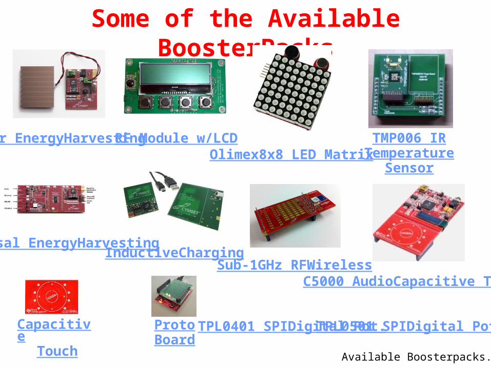
Some of the Available BoosterPacks
TMP006 IRTemperature
Sensor
C5000 AudioCapacitive Touch
Olimex8x8 LED Matrix
Sub-1GHz RFWireless
TPL0501 SPIDigital Pot.TPL0401 SPIDigital Pot.
RF Module w/LCD
InductiveCharging
Solar EnergyHarvesting
Universal EnergyHarvesting
CapacitiveTouch
ProtoBoard
Available Boosterpacks...

Some of the Available BoosterPacks
Proto board ZigBee Networking OLED Display
LCD Controller Development Package Click BoardAdapterMOD BoardAdapter
Kentec LCD Display...

KenTec TouchScreen TFT LCD Display
Part# EB-LM4F120-L35 Designed for XL BoosterPack pinout 3.5” QVGA TFT 320x240x16 color LCD
with LED backlight Driver circuit and connector are
compatible with 4.3”, 5”, 7” & 9”displays Resistive Touch Overlay
grLib Overview...

Graphics Library Overview
The Tiva C Series Graphics Library provides graphics primitives and widgets sets for creating graphical user interfaces on Tiva controlled displays.
Note that Tiva devices do not have an LCD interface. The interface to smart displays is done through serial or EPI ports.
The graphics library consists of three layers to interface your application to the display:
Display Driver Layer*
Graphics Primitives Layer
Widget Layer
Your Application Code*
* = user written or modifiedgrLib Overview...

Graphics Library Overview
The design of the graphics library is governed by the following goals:
Components are written entirely in C except where absolutely not possible. Your application can call any of the layers. The graphics library is easy to understand. The components are reasonably efficient in terms of memory and processor
usage. Components are as self-contained as possible. Where possible, computations that can be performed at compile time are
done there instead of at run time.
Display Driver...

Display Driver
Routines for display-dependent operations like: Initialization Backlight control Contrast Translation of 24-bit RGB values to screen dependent color map
Drawing routines for the graphics library like: Flush Line drawing Pixel drawing Rectangle drawing
User-modified Hardware Dependent Code Connectivity of the smart display to the LM4F Changes to the existing code to match your
display (like color depth and size)
Low level interface to the display hardware
Graphics Primitives...

Graphics Primitives
Low level drawing support for:
Lines, circles, text and bitmap images Support for off-screen buffering Foreground and background drawing contexts Color is represented as a 24-bit RGB value (8-bits per color)
~150 pre-defined colors are provided 153 pre-defined fonts based on the Computer Modern typeface Support for Asian and Cyrillic languages
Widgets...
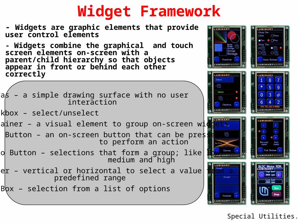
Widget Framework- Widgets are graphic elements that provide user control elements
- Widgets combine the graphical and touch screen elements on-screen with a parent/child hierarchy so that objects appear in front or behind each other correctly
Canvas – a simple drawing surface with no user interaction
Checkbox – select/unselect
Container – a visual element to group on-screen widgets
Push Button – an on-screen button that can be pressed to perform an action
Radio Button – selections that form a group; like low, medium and high
Slider – vertical or horizontal to select a value from a predefined range
ListBox – selection from a list of options
Special Utilities...

Special UtilitiesUtilities to produce graphics library compatible data structures
ftrasterize Uses the FreeType font rendering package to convert your font into a graphic library format. Supported fonts include: TrueType®, OpenType®, PostScript® Type 1 and Windows® FNT.
lmi-button Creates custom shaped buttons using a script plug-in for GIMP. Produces images for use by the pushbutton widget.
pnmtoc Converts a NetPBM image file into a graphics library compatible file. NetPBM image formats can be produced by: GIMP, NetPBM, ImageMajik and others.
mkstringtable Converts a comma separated file (.csv) into a table of strings usable by graphics
library for pull down menus.
Lab...
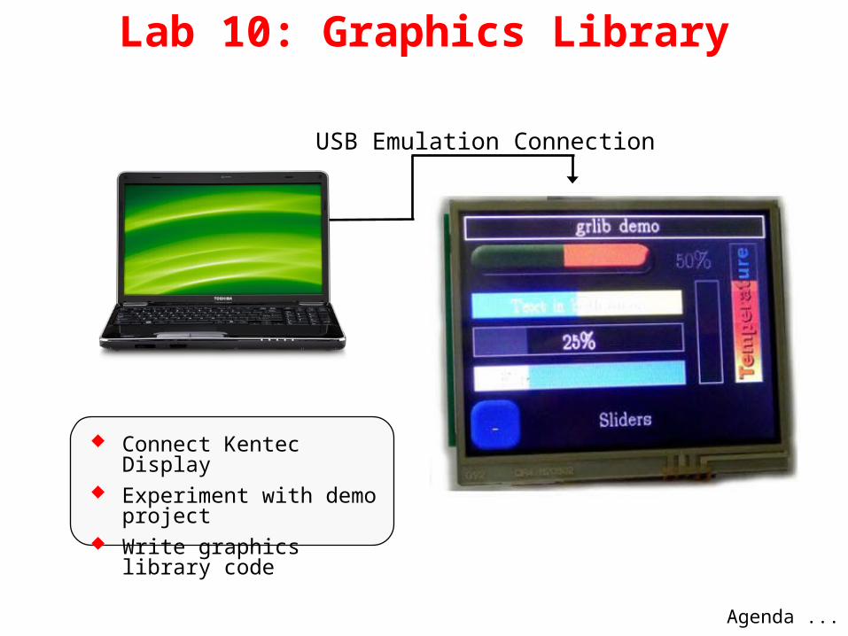
Lab 10: Graphics Library
Connect Kentec Display Experiment with demo
project Write graphics library code
USB Emulation Connection
Agenda ...

Agenda
Features...
Introduction to ARM® Cortex™-M4F and Peripherals
Code Composer Studio
Introduction to TivaWare™, Initialization and GPIO
Interrupts and the Timers
ADC12
Hibernation Module
USB
Memory
Floating-Point
BoosterPacks and grLib
Synchronous Serial Interface
UART
µDMA

TM4C123GH6PM SSI Features
Block Diagram ...
Four SSI modules. Each with: Freescale SPI, MICROWIRE or TI Synchronous Serial interfaces Master or Slave operation Programmable bit clock rate and pre-scaler Programmable data frame size from 4 to 16-bits Separate Tx and Rx FIFOs ( 8 x16-bits ) Interrupts and µDMA support

SSI Block Diagram
Interrupts...
Signal Pinout (n = 0 to 3) …
SSInClk: SSI Module n Clock
SSInFss: SSI Module n Frame Signal
SSInRx: SSI Module n Receive
SSInTx: SSI Module n Transmit

SSI Interrupts
Operation...
Single interrupt per module, cleared automatically
Interrupt conditions:
Transmit FIFO service (when the transmit FIFO is half full or less) Receive FIFO service (when the receive FIFO is half full or more) Receive FIFO time-out Receive FIFO overrun End of transmission Receive DMA transfer complete Transmit DMA transfer complete
Interrupts on these conditions can be enabled individually
Your handler code must check to determine the source of the SSI interrupt and clear the flag(s)

SSI µDMA Operation
Separate channels for Tx and Rx When enabled, the SSI will assert a DMA request on either channel
when the Rx or Tx FIFO can transfer data For Rx channel: A single transfer request is made when any data is in the
Rx FIFO. A burst transfer request is made when 4 or more items is in the Rx FIFO.
For Tx channel: A single transfer request is made when there is at least one empty location in the Tx FIFO. A burst transfer request is made when 4 or more slots are empty.
Signal Formats...
1 2
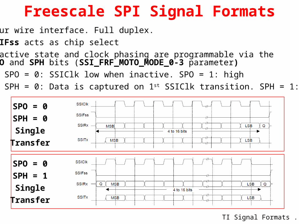
Freescale SPI Signal Formats
TI Signal Formats ...
Four wire interface. Full duplex. SSIFss acts as chip select Inactive state and clock phasing are programmable via the
SPO and SPH bits (SSI_FRF_MOTO_MODE_0-3 parameter) SPO = 0: SSIClk low when inactive. SPO = 1: high SPH = 0: Data is captured on 1st SSIClk transition. SPH = 1: 2nd
SPO = 0
SPH = 0
Single
Transfer
SPO = 0
SPH = 1
Single
Transfer

TI Synchronous Serial Signal Formats
Microwire Signal Formats...
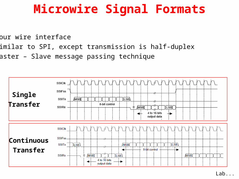
Three wire interface Devices are always slaves SSIClk and SSIFss are forced low and SSITx is tri-stated
when the SSI is idle
Single
Transfer
Continuous
Transfer
Microwire Signal Formats
Lab...
Four wire interface Similar to SPI, except transmission is half-duplex Master – Slave message passing technique
Single
Transfer
Continuous
Transfer
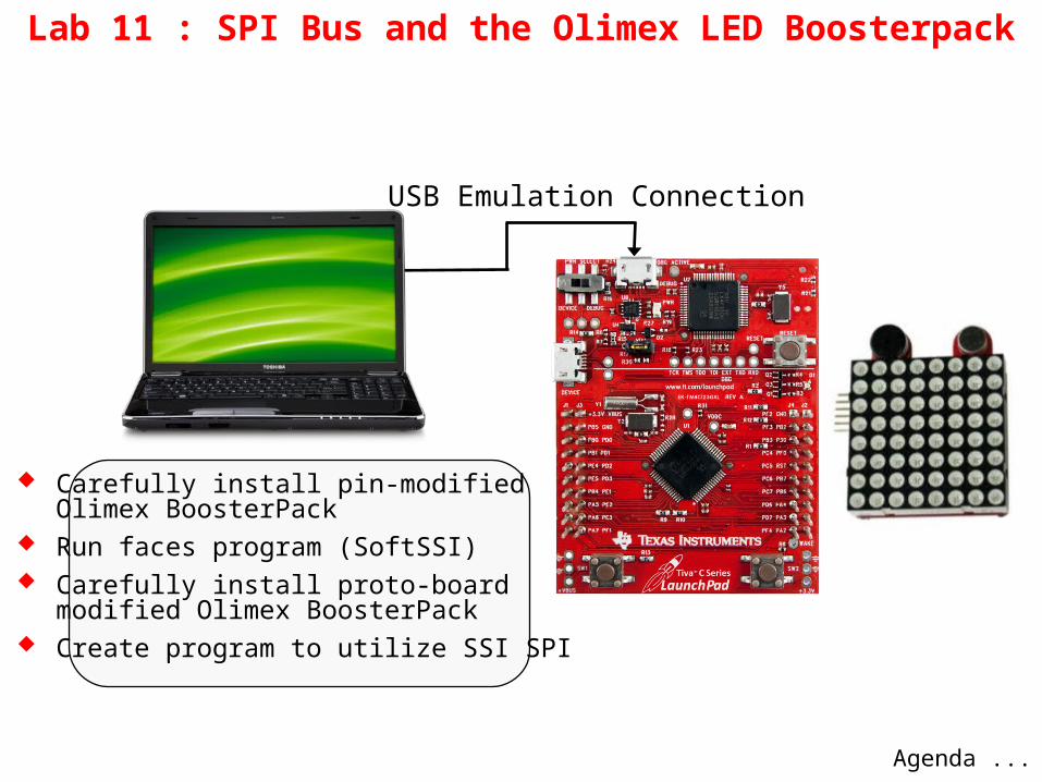
Lab 11 : SPI Bus and the Olimex LED Boosterpack
Carefully install pin-modified Olimex BoosterPack
Run faces program (SoftSSI) Carefully install proto-board
modified Olimex BoosterPack Create program to utilize SSI SPI
USB Emulation Connection
Agenda ...

Agenda
Features...
Introduction to ARM® Cortex™-M4F and Peripherals
Code Composer Studio
Introduction to TivaWare™, Initialization and GPIO
Interrupts and the Timers
ADC12
Hibernation Module
USB
Memory
Floating-Point
BoosterPacks and grLib
Synchronous Serial Interface
UART
µDMA

UART Features Separate 16x8 bit transmit and receive FIFOs Programmable baud rate generator Auto generation and stripping of start, stop, and
parity bits Line break generation and detection Programmable serial interface
5, 6, 7, or 8 data bits even, odd, stick, or no parity bits 1 or 2 stop bits baud rate generation, from DC to processor clock/16
Modem flow control on UART1 (RTS/CTS) IrDA and EIA-495 9-bit protocols µDMA support
Block Diagram...

Block Diagram
Basic Operation...

Basic Operation Initialize the UART
Enable the UART peripheral, e.g.SysCtlPeripheralEnable(SYSCTL_PERIPH_UART0);SysCtlPeripheralEnable(SYSCTL_PERIPH_GPIOA);
Set the Rx/Tx pins as UART pinsGPIOPinConfigure(GPIO_PA0_U0RX);GPIOPinConfigure(GPIO_PA1_U0TX);GPIOPinTypeUART(GPIO_PORTA_BASE, GPIO_PIN_0 | GPIO_PIN_1);
Configure the UART baud rate, data configuration ROM_UARTConfigSetExpClk(UART0_BASE, ROM_SysCtlClockGet(), 115200, UART_CONFIG_WLEN_8 | UART_CONFIG_STOP_ONE | UART_CONFIG_PAR_NONE));
Configure other UART features (e.g. interrupts, FIFO) Send/receive a character
Single register used for transmit/receive Blocking/non-blocking functions in driverlib:
UARTCharPut(UART0_BASE, ‘a’);newchar = UARTCharGet(UART0_BASE);UARTCharPutNonBlocking(UART0_BASE, ‘a’);newchar = UARTCharGetNonBlocking(UART0_BASE);
Interrupts...

UART InterruptsSingle interrupt per module, cleared automatically
Interrupt conditions: Overrun error Break error Parity error Framing error Receive timeout – when FIFO is not empty and no further data is
received over a 32-bit period Transmit – generated when no data present (if FIFO enabled, see next
slide) Receive – generated when character is received (if FIFO enabled, see
next slide)
Interrupts on these conditions can be enabled individually
Your handler code must check to determine the source of the UART interrupt and clear the flag(s)
FIFOs...

Using the UART FIFOs
Both FIFOs are accessed via the UART Data register (UARTDR)
After reset, the FIFOs are enabled*, you can disable by resetting the FEN bit in UARTLCRH, e.g.
UARTFIFODisable(UART0_BASE);
Trigger points for FIFO interrupts can be set at 1/8, 1/4, 1/2,3/4, 7/8 full, e.g.
UARTFIFOLevelSet(UART0_BASE, UART_FIFO_TX4_8, UART_FIFO_RX4_8);
Transmit FIFO
UART_FIFO_TX4_8
UART_FIFO_TX1_8
UART_FIFO_TX2_8
UART_FIFO_TX6_8
UART_FIFO_TX7_8
FIFO Level Select
* Note: the datasheet says FIFOs are disabled at reset
stdio Functions...

UART “stdio” Functions TivaWare “utils” folder contains functions for C stdio
console functions:c:\TivaWare\utils\uartstdio.hc:\TivaWare\utils\uartstdio.c
Usage example:UARTStdioInit(0); //use UART0, 115200UARTprintf(“Enter text: “);
See uartstdio.h for other functions Notes:
Use the provided interrupt handler UARTStdioIntHandler() code in uartstdio.c
Buffering is provided if you define UART_BUFFERED symbol
Receive buffer is 128 bytes Transmit buffer is 1024 bytes
Other UART Features...
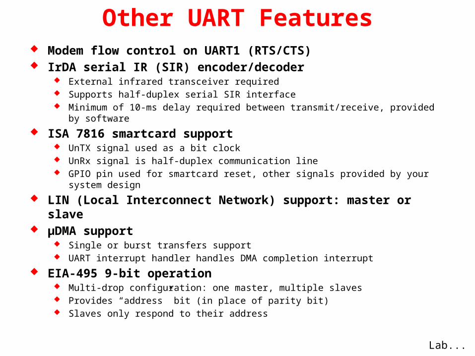
Other UART Features Modem flow control on UART1 (RTS/CTS) IrDA serial IR (SIR) encoder/decoder
External infrared transceiver required Supports half-duplex serial SIR interface Minimum of 10-ms delay required between transmit/receive, provided by software
ISA 7816 smartcard support UnTX signal used as a bit clock UnRx signal is half-duplex communication line GPIO pin used for smartcard reset, other signals provided by your system design
LIN (Local Interconnect Network) support: master or slave µDMA support
Single or burst transfers support UART interrupt handler handles DMA completion interrupt
EIA-495 9-bit operation Multi-drop configuration: one master, multiple slaves Provides “address” bit (in place of parity bit) Slaves only respond to their address
Lab...

Initialize UART and echo characters using polling
Use interrupts
Lab 12: UART
USB Emulation Connection

Agenda
Features...
Introduction to ARM® Cortex™-M4F and Peripherals
Code Composer Studio
Introduction to TivaWare™, Initialization and GPIO
Interrupts and the Timers
ADC12
Hibernation Module
USB
Memory
Floating-Point
BoosterPacks and grLib
Synchronous Serial Interface
UART
µDMA

µDMA Features
Transfer types...
32 channels SRAM to SRAM , SRAM to peripheral and peripheral to
SRAM transfers (no Flash or ROM transfers are possible) Basic, Auto (transfer completes even if request is removed),
Ping-Pong and Scatter-gather (via a task list) Two priority levels 8, 16 and 32-bit data element sizes Transfer sizes of 1 to 1024 elements (in binary steps) CPU bus accesses outrank DMA controller Source and destination address increment sizes:
size of element, half-word, word, no increment Interrupt on transfer completion (per channel) Hardware and software triggers Single and Burst requests Each channel can specify a minimum # of transfers before
relinquishing to a higher priority transfer. Known as “Burst” or “Arbitration”

Transfer TypesBasic
Single to Single Single to Array Array to Single Array to Array
Auto Same as Basic but the transfer completes even if the request is
removed
Ping-Pong Single to Array (and vice-versa). Normally used to stream data from
a peripheral to memory. When the PING array is full the µDMA switches to the PONG array, freeing the PING array for use by the program.
Scatter-Gather Many Singles to an Array (and vice-versa). May be used to read
elements from a data stream or move objects in a graphics memory frame.
Block diagram...

µDMA Block Diagram
Channels...
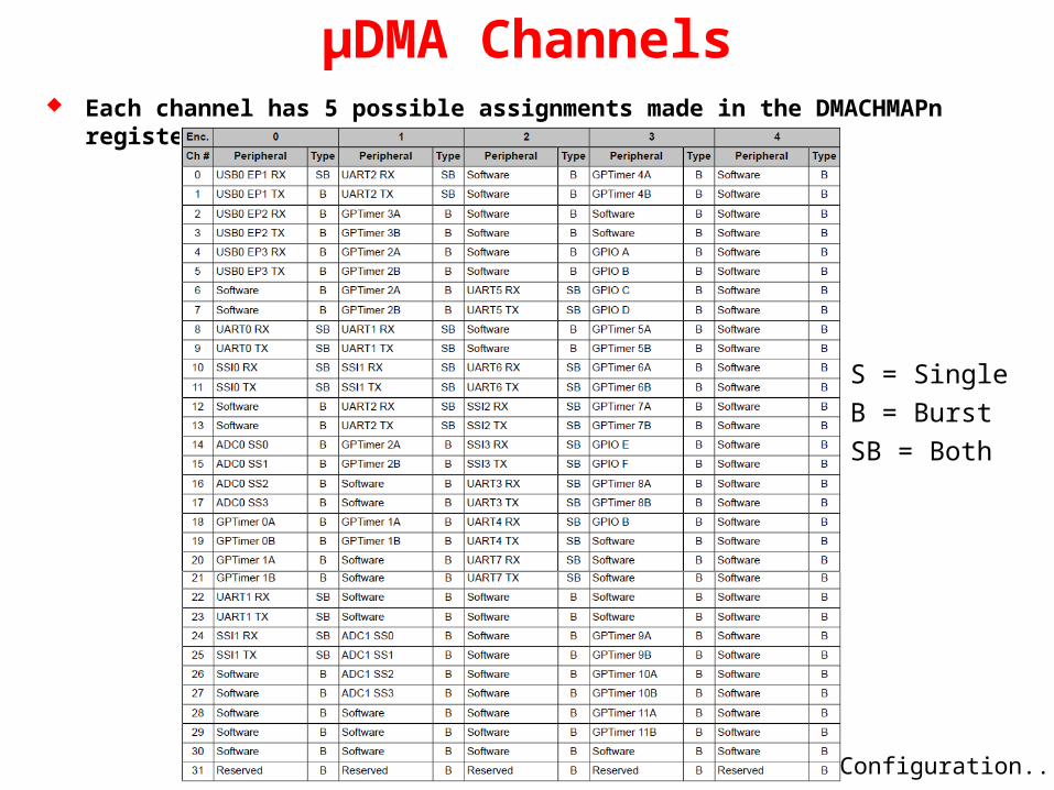
µDMA Channels Each channel has 5 possible assignments made in the DMACHMAPn register
S = Single
B = Burst
SB = Both
Configuration...

Channel Configuration Channel control is done via a set of control structures in a table The table must be located on a 1024-byte boundary Each channel can have one or two control structures; a primary and an alternate The primary structure is for BASIC and AUTO transfers. Alternate is for Ping-Pong
and Scatter-gather
Control Structure Memory Map Channel Control Structure
Control word contains: Source and Dest data sizes Source and Dest addr increment size # of transfers before bus arbitration Total elements to transfer Useburst flag Transfer mode
Lab...

Lab 13: Transferring Data with the µDMA
Perform an array to array memory transfer
Transfer data to and from the UART
USB Emulation Connection
Wrap-up ...

Thanks for Attending!
Make sure to take your kits and workbooks with you
Please leave the TTO flash drives and meters here
Please fill out the feedback form Have safe trip home!

Presented by
Texas Instruments
Technical Training Organization
www.ti.com/training


