TM 11-5821-333-12 OPERATOR’S AND AVIATION UNIT MAINTENANCE MANUAL SINCGARS AIRBORNE COMBAT NET RADIO, ICOM AND NON-ICOM NON-ICOM AIRBORNE RADIO AN/ARC-201(V) (NSN: N/A) (EIC: N/A) ICOM AIRBORNE RADIO AN/ARC-201A(V) (NSN: N/A) (EIC: N/A) Approved for public release; distribution is unlimited. HEADQUARTERS, DEPARTMENT OF THE ARMY 1 SEPTEMBER 1992
Transcript
TM 11-5821-333-12
OPERATOR’S AND AVIATIONUNIT
MAINTENANCE MANUAL
SINCGARS AIRBORNECOMBAT NET RADIO,ICOM AND NON-ICOM
NON-ICOM AIRBORNE RADIO
AN/ARC-201(V)
(NSN: N/A) (EIC: N/A)
ICOM AIRBORNE RADIO
AN/ARC-201A(V)
(NSN: N/A) (EIC: N/A)
Approved for public release; distribution is unlimited.
HEADQUARTERS, DEPARTMENT OF THE ARMY
1 SEPTEMBER 1992
INTRODUCTION PAGE 1-1
CONTROLS ANDINDICATORS PAGE 2-2
SCOPERATING PROCEDURES PAGE 2-8
OPERATING PROCEDURES PAGE 2-11
ADDITIONALOPERATING PROCEDURES PAGE 4-1
OPERATION UNDERUNUSUAL CONDITIONS PAGE 4-4
OPERATORMAINTENANCE PAGE 5-1
AVIATION UNITMAINTENANCE PAGE 6-1
GLOSSARYPAGE E-1
FH
NCSOPERATING PROCEDURES PAGE 3-1
TM 11-5821-333-12
SAFETY STEPS TO FOLLOW IF SOMEONE ISTHE VICTIM OF ELECTRICAL SHOCK
DO NOT TRY TO PULL OR GRAB THE INDIVIDUAL.
IF POSSIBLE TURN OFF THE ELECTRICAL POWER.
IF YOU CANNOT TURN OFF THE ELECTRICAL POWER, PULL, PUSH,OR LIFT THE PERSON TO SAFETY USING A DRY WOODEN POLE ORA DRY ROPE OR SOME OTHER INSULATING MATERIAL.
SEND FOR HELP AS SOON AS POSSIBLE.
AFTER THE INJURED PERSON IS FREE OF CONTACT WITH THESOURCE OF ELECTRICAL SHOCK, MOVE THE PERSON A SHORTDISTANCE AWAY AND IMMEDIATELY STARTRESUSCITATION.
FOR ARTIFICIAL RESPIRATION, REFER TO FM 21-11.
RF ENERGY is present near the antenna during transmission.antenna when the RT is keyed.
ARTIFICIAL
DO NOT touch or stand within 30 inches of
HIGH VOLTAGE is used in the radio. DEATH ON CONTACT can result. Observe the following safety precautions: If possible, work on the equipment only when another person is nearby. That person should be
competent in CARDIOPULMONARY RESUSCITATION (CPR). Both of you need to know the five safetysteps listed above.
DO NOT BE MISLED by the terms “low voltage” and “low potential.” Voltages and potentials as low as50 volts can cause death.
Remove or tape all your exposed personal metal objects when working on C-E equipment.DEATH OR SERIOUS INJURY can result from the improper use of solvent TRICHLOROTRIFLUOROETHANE,Fumes from this solvent are toxic (poisonous). Prolonged breathing of vapors must be avoided. This solventdissolves natural skin oils. Prolonged contact with skin must be avoided. Use TRICHLOROTRIFLUOROETHANEonly when:
Adequate ventilation is provided. Protective goggles, gloves, sleeves, and an apron are worn.
DO NOT use compressed air to dry parts.If solvent is taken internally, CONSULT A DOCTOR IMMEDIATELY.
DO NOT under any circumstances remove printed circuit boards fromthe equipment. The boards in this radio are static sensitive. If you re-move them in the field, you will destroy them. Do not open any unit.
A/(B blank)
*TM 11-5821-333-12
Technical Manual HeadquartersDepartment of the Army
No. 11-5821-333-12 Washington, D.C. 1 September 1992
TABLE OF CONTENTS
OPERATOR’S AND AVIATION UNIT MAINTENANCE MANUALNON-ICOM (AN/ARC-201(V)) (NSN:N/A) (EIC:N/A) and
ICOM (AN/ARC-201A(V)) (NSN:N/A) (EIC:N/A) RADIO SETS
Approved for public release; distribution is unlimited.
COVER. Information that you will use most often is boxed on the front cover. The boxed information found on thefront cover is thumb-indexed with edge marks so that you may quickly refer to that information.
TABLE OF CONTENTS. Refer to the Table of Contents to find out where information can be found. The Table of Contents lists each chapter title, section heading, and main subject item. Under each chapter title, sectionheadings are listed. Under each section heading, main subjects are listed.
INDEX. Refer to the index at the back of this manual to locate specific subjects. The information is broken downby subject matter and is listed alphabetically, Look for the subject you need to know about; then turn to theparagraph listed.
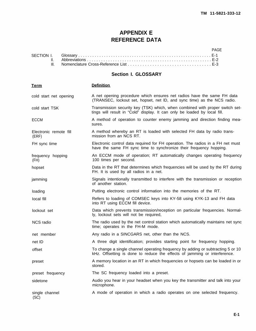
GLOSSARY. Refer to the glossary in Appendix E in the back of this manual to find the meaning of an unfamiliarterm.
ABBREVIATIONS. Refer to the list of abbreviations in Appendix E in the back of this manual to find the termassociated with an unfamiliar abbreviation.
NOMENCLATURE CROSS-REFERENCE LIST. Refer to the nomenclature cross-reference list in Appendix E inthe back of this manual to find common names and official nomenclature.
OPERATIONAL NOTES
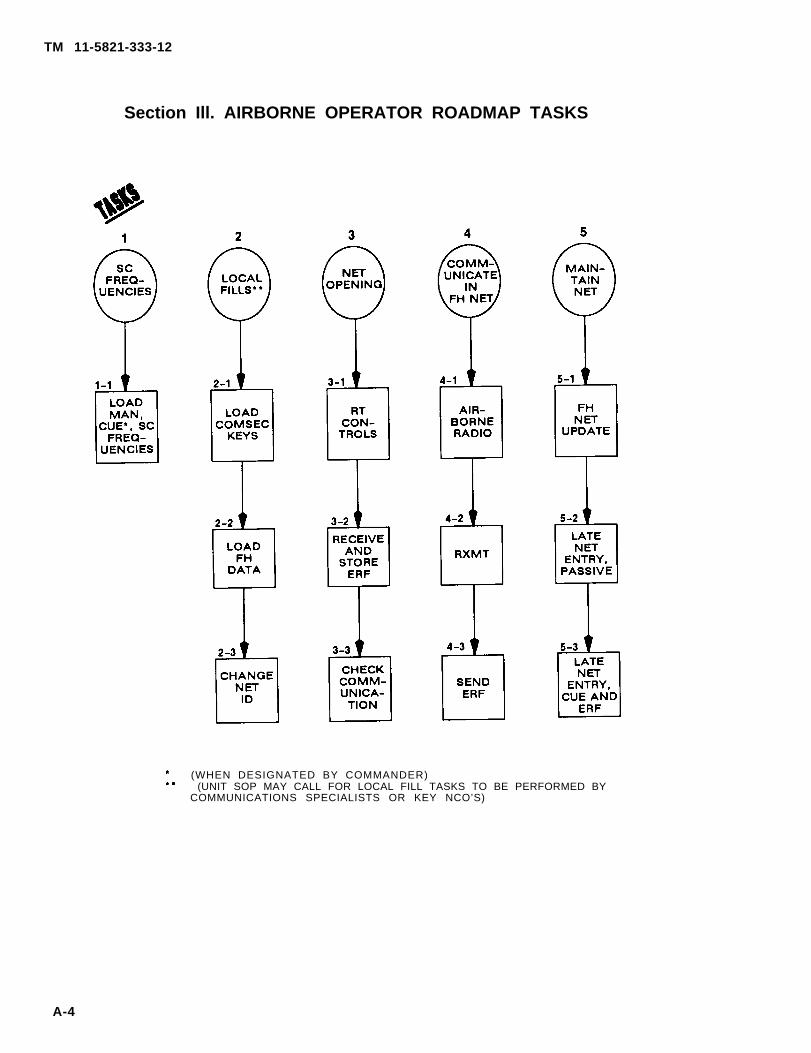
OPERATOR PROCEDURES. A roadmap and functional flow charts are provided in Appendix A which offer opera-tor graphic aids that may be helpful in learning and recalling basic operator tasks.
PROCEDURE INSTRUCTIONS. Procedures can be found under the appropriate heading. Refer to the index to find a procedure quickly. Most procedures have instructions that are lettered a, b, c, and so on. Always beginwith step a: then do the rest of the steps in order.
OPERATING DISPLAYS. Examples of display data are shown throughout your manual. The letters you see onequipment displays must match the examples shown. In most examples, numbers are represented by “X”s.However, the numbers (0, 1, 2, 3, 4, 5, 6, 7, 8, 9) you see on your equipment displays may differ from theexamples. If equipment displays do not match the examples shown, make sure you have done the procedurecorrectly.
WARNING PAGES are at the beginning of this manual. You should learn the warnings before doing maintenanceon the equipment. Always follow appropriate safety procedures and precautions.
This chapter provides a general introduction to the SINCGARS airborne Non-lCOM and ICOM operator’s andunit maintenance manual. This manual is intended to be used by Operators, NCS personnel, and AVUM Main-tainers. SINCGARS is designed for secure voice and data communication and is the only anti-jam radio that ispart of a total system. SINCGARS is capable of two modes of operation: single channel and frequency hopping.The radio sets handle both voice and data communications. The introduction includes information about how toreport errors, equipment problems, suggested improvements, and security information, It also contains a sec-tion that describes equipment capabilities and features, characteristics, performance, weights, and measure-ments as well as illustrations and text that show and describe major components, The technical principles ofoperation are detailed descriptions of operational functions of SINCGARS, and are provided only for information.For simplified operator’s information, refer to Chapter 2. The manual gives information for the operation andmaintenance of the Non-lCOM radio (AN/ARC-201 (V)) and ICOM radio (AN/ARC-201A(V)). Where radio con-trols differ between the ICOM and Non-lCOM radios, the ICOM control will be shown first, followed by the Non-ICOM control in parenthesis; i.e.; “ SYNC” (“ L. E.)”. The manual also provides information about ECCM fill de-vice, various mounts, data rate adapter, and RT/RCU’s.
1-2. MAINTENANCE FORMS, RECORDS, AND REPORTS.a. Reports of Maintenance and Unsatisfactory Equipment. Department of the Army forms and proce-
dures used for equipment maintenance will be those prescribed by DA PAM 738-750 as contained in Mainte-nance Management Update.
b. Reporting of Item and Packaging Discrepancies. Fill out and forward SF 364 (Report of Discrepancy(ROD)) as prescribed in AR 735-11-2/DLAR 4140.55/SECNAVINST 4355.18/AFR 400-54/MCO 4430.3J.
c. Transportation Discrepancy Report (TDR) (SF 361). Fill out and forward Transportation DiscrepancyReport (TDR) (SF 361) as prescribed in AR 55-38 /NAVSUPlNST 4610.33C/AFR 75-18/MCO P4610.19D/DLAR4500.15.
1-3. CONSOLIDATED INDEX OF ARMY PUBLICATIONS AND BLANK FORMSRefer to the latest issue of DA Pam 25-30 to determine whether there are new editions, changes, or additionalpublications pertaining to the equipment.
1-4. EQUIPMENT IMPROVEMENT RECOMMENDATIONS (EIR).
If your series of radio sets needs improvement, let us know. Send us an EIR. You, the user, are the only one whocan tell us what you don’t like about the design. Put it on an SF 368 (Product Quality Deficiency Report). Mail it to:Commander, US Army Communications-Electronics Command and Fort Monmouth, ATTN: AMSEL-ED-PH,Fort Monmouth, NJ 07703–5007. We’ll send you a reply.
1-1
TM 11-5821-333-12
1-5. REPORTING ERRORS AND RECOMMENDING IMPROVEMENTS.You can help improve this manual. If you find any mistakes or if you know of a way to improve the procedures,please let us know. Mail your letter, DA Form 2028 (Recommended Changes to Publications and Blank Forms), or DA Form 2028-2 located in the back of this manual direct to: Commander, U.S. Army Communications-Elec-tronics Command and Fort Monmouth, ATTN: AMSEL-LC-LM-LT, Fort Monmouth, NJ 07703-5007. In eithercase, a reply will be furnished direct to you.
1-6. SECURITY CLASSIFICATION AND MARKING.(Not Applicable.)
1-7. DESTRUCTION OF ARMY MATERIEL TO PREVENT ENEMY USE.Destruction of Army electronics C-E to prevent enemy use shall be in accordance with TM 750-244-2.
1-8. CAPABILITIES AND FEATURES.The Non-lCOM and ICOM radio components may be arranged in a variety of configurations for VHF-FM commu-nications of an aircraft or ground based systems to provide:
Single channel and frequency hopping operation in VHF band (30-87.975 MHz),
Eight single channel and six frequency hopping PRESET channels,
CUE channel for contact of frequency hopping net by non-member,
Quick, silent electronic tuning, Visual electronic displays: provide for quick checks and prompts during operation,
Self test, Voice, FSK data, and digital data communication,
Provisions for control of optional IFM power amplifier,
Secure communications using KY-58 COMSEC equipment.
The Non-lCOM radio will operate with the following aircraft communications system equipment:
KY-58 COMSEC equipment
Z-AHP remote control unit
Z-AHQ interface adapter
ID-1351A or ID-2403 (or equivalent) indicator
C-1611/ARC, C-6533/ARC, C-10414(V)/ARC, or C-11746(V)/ARC intercom equipment
AM-7189A/ARC power amplifier
CP-1516/ASQ airborne target handover system
VHF-FM (30-88 MHz) communication and homing antennas
1-2
1-9. DESCRIPTION OF MAJOR COMPONENTS.The components which may be used in the Non-lCOM
TM 11-5821-333-12
and ICOM radio sets are listed in the following table:
Control, Radio SetC-11466/ARC-201(V) XNSN 5821-01-231-5660
Control, Radio SetC-11466A/ARC-201A(V) XNSN 5821-01-306-2245
Adapter, Data RateCV-3885/ARC-201(V) X XNSN 5821-01-231-5593
Mounting Base, ElectricalEquipmentMT-6373/ARC-201(V) X XNSN 5821-01-231-5667
Mounting Base, ElectricalEquipmentMT-6374/ARC-201(V) X XNSN 5821-01-231-5668
Box, BatteryCY-8515/ARC-201 (V) X XNSN 6135-01-266-7596
NOTE: (V) - Indicates that the radio set may consist of varied units.A – Indicates that this version of the radio set is a modification
of an existing set.
1-3
TM 11-5821-333-12
1-9. DESCRIPTION OF MAJOR COMPONENTS. Continued
The Radio Receiver-Transmitters (RTs) are two-way FM radios. They can be loaded with eight single channel(SC) and six frequency hopping (FH) presets. The system connector and auxiliary connector link the RT to theaircraft system and to other radio set components. For retransmit operation, two RTs are connected via theirsystem connectors. An ECCM fill device is connected to the FILL connector to load data needed for FH opera-tion. There are connectors for a communications antenna and two homing antennas. In the HOM (homing)mode, a homing indicator is driven from the system connector. Using the homing indicator, the pilot can steer toan FM transmitter. The RT does not require adjustment, alignment, or calibration. Self-test is provided for diag- nostic use. There are three types of RT installations:
a. Panel RT. The panel RTs have all user controls on the RT front panel. RT-1476 is used in theARC-201(V) radio set, RT-1476A used in the ARC-201A(V).
b. Remote RT. The RT-1477 must be used with a Radio Set Control C-11466/ARC-201 (V). The RT-1477Amust be used with a Radio Set Control C-11466A/ARC-201A(V). The RT is mounted remotely from the operatoron a Mounting Base, Electrical Equipment MT-6373/ARC-201(V) or MT-6374/ARC-201(V).
c. Bus RT. These (RT-1478 or RT-1478A) must be used with the aircraft MlL-STD-l553B bus controller.The RT is mounted remotely from the operator on a Mounting Base, Electrical Equipment MT-6374/ARC-201(V).Interface between the RT and bus controller is via the address connector and the two data connectors, bus A andbus B.
1-4
TM 11-5821-333-12
1-9. DESCRIPTION OF MAJOR COMPONENTS. Continued
Control Radio Set C-11466/ARC-201-(V) or C-11466A/ARC-201A(V)
The Control, Radio Set C-11466/ARC-201 (V) remotely controls the RT-1477/ARC-201(V). The Control, RadioSet C-11466A/ARC-201A(V) remotely controls the RT-1477A/ARC-201 A(V) . These remote control units(RCUs) are mounted in the aircraft console and the RT is mounted remotely. One or more RCUs may be usedwith each RT, A C-11466 RCU may also be used to remotely control an RT-1476 RT, and a C-11466A may beused to remotely control an RT-1476A RT. The RCU controls are the same as the controls on theRT-1476/RT-1476A RT. A connector is on the back of the RCU. Self-test is provided for diagnostic use.
The Battery Box, CY-8515/ARC-201 (V), is intended to provide an alternative to the Hold Up Battery (HUB) in anRT. It accepts five C-cell batteries. It is wired to connect five batteries in series. The combined output is used asan external hold up battery for the RT, The battery box and the RT internal HUB can be used together. When usedtogether, the battery box serves as the primary power source. The battery box and the HUB serve as mutualbackup power sources.
1-5
TM 11-5821-333-12
1-9. DESCRIPTION OF MAJOR COMPONENTS. Continued
The Mounting Base, Electrical Equipment MT-6373/ARC-201(V) is an adapter designed to hold theRT-1477/ARC-201(V) or RT-1477A/ARC-201A(V). It allows the RT to be used as a replacement for an AN/ARC-54/131/186. The mounting base has cables that connect to the RT-1477 or RT-1477A. The mounting baseplugs into the AN/ARC-54/131/186 mounting base. The RT-1477 or RT-1477A can be installed in the mountingbase external to the aircraft. The mounting base with RT can then be used in the aircraft in place of an AN/ARC-54/131/186. A pivoting handle locks the mounting base in place. The CY-8515/ARC-201(V) batterybox may be mounted inside the bottom of the mounting base.
The Mounting Base, Electrical Equipment MT-6374/ARC-201(V) accepts the RT-1477/ARC-201(V), RT-1477A/ARC-201A(V), RT-1478/ARC-201(V), or RT–1478A/ARC-201A(V). This base is a mechanical mount only. Elec-trical connections to the aircraft system and auxiliary equipment are made directly to the RT connectors.
1-6
TM 11-5821-333-12
1-9. DESCRIPTION OF MAJOR COMPONENTS. Continued
The Adapter, Data Rate CV–3885/ARC-201(V) provides interface between the AN/ARC-201(V) RT and analogdata devices such as TACFIRE. It conditions data signals to the 16 kb/s digital rate required by the RT. It alsointerfaces with the KY-58 COMSEC equipment. The adapter controls the operating mode of the RT and KY-58 toestablish digital or analog operation. The radio connector on the data rate adapter (DRA) connects to the RTeither directly or through the Z-AHQ COMSEC interface adapter. The intercom connector connects to the inter-com either directly or through the Z-AHQ COMSEC interface adapter. The COMSEC radio and audio/data con-nectors on the DRA connect to the KY-58 COMSEC equipment (if used).
The Fill Devices, ECCM MX-10579/VRC and MX-18290/VRC store frequency hopping fill data. TheMX-10579/VRC is used with RT-1476, RT-1477, and RT-1478RT. The MX-18290/VRC maybe used with all RTs.The ECCM fill devices can receive fill data from another ECCM fill device. Thirteen FH hopsets or lockout sets andtwo TRANSEC variables may be loaded into memory. TRANSEC variables are loaded into Non-lCOM radio setsonly.
1-7
TM 11-5821-333-12
1-10. DIFFERENCES BETWEEN MODELS.There are three versions of the receiver-transmitter:
The panel RT (RT-1476/ARC-201(V) or RT-1476A/ARC-201A(V)) is controlled from its front panel. It isdesigned to be mounted in the aircraft cockpit.
Remote RT-1477/ARC-201(V) is a remote controlled receiver-transmitter used with the C-11466/ARC-201(V) radio set control (RCU). Remote RT-1477A/ARC-201A(V) is a remote controlled receiver-transmitter used with the C-11466A/ARC-201A(V) radio set control. All controls are on the RCU. The RCUis located in the aircraft cockpit. The RT is located in a remote equipment compartment of the aircraft.Control and status signals are sent back and forth between the RT and RCU via dedicated cables.
The Bus RT(RT-1478/ARC-201(V) or RT-1478A/ARC-201A(V)) is a remote controlled receiver-transmit-ter used in MIL-STD-1553B data bus aircraft. The RT is controlled by the aircraft system control-displayunit. The RT is located in a remote equipment compartment of the aircraft. Operating instructions are inthe aircraft systems operator’s technical manual, and are not in this manual. .
The optional Data Rate Adapter (CV-3885/ARC-201(V)) processes 1200/2400 Hz FSK data through the radioset for data transmission and interfaces between the RT and KY-58 COMSEC equipment. Operation of the datarate adapter is automatic. There is no operator interface.
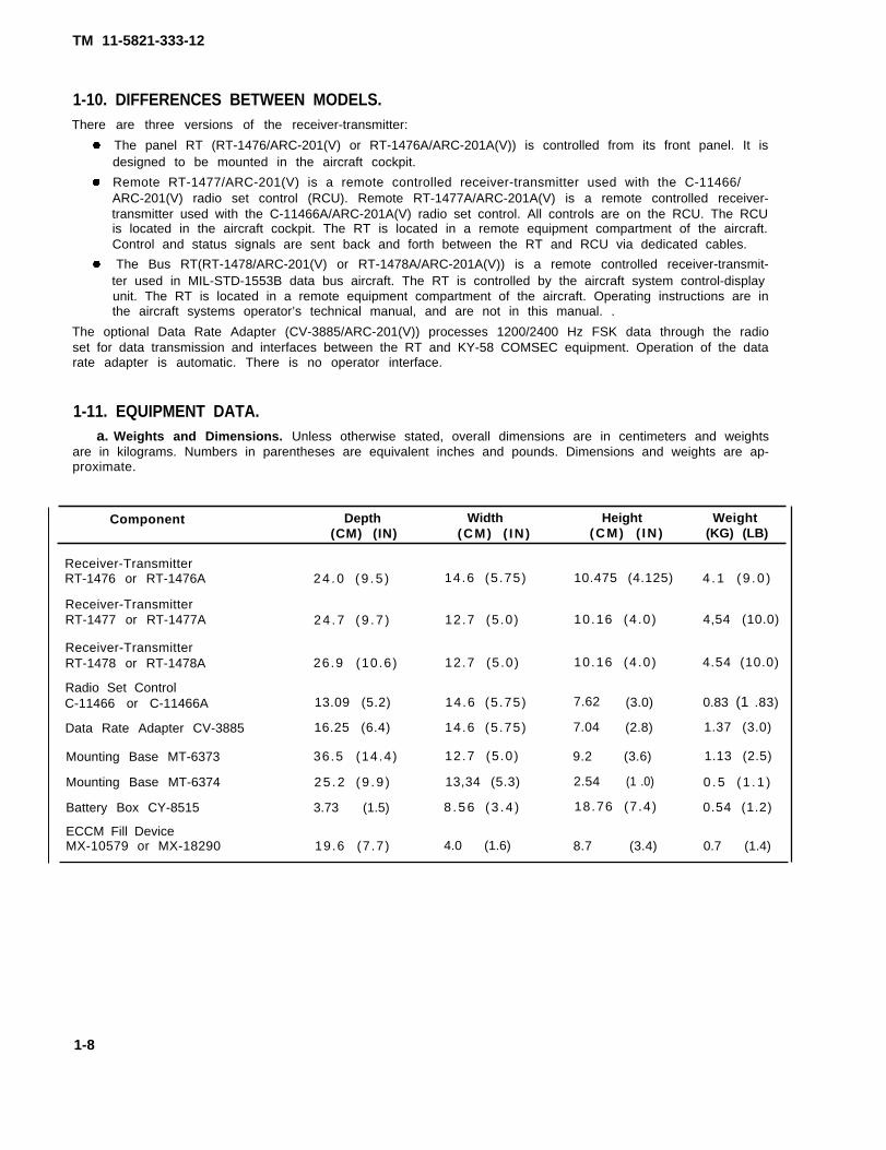
1-11. EQUIPMENT DATA.a. Weights and Dimensions. Unless otherwise stated, overall dimensions are in centimeters and weights
are in kilograms. Numbers in parentheses are equivalent inches and pounds. Dimensions and weights are ap-proximate.
Component Depth Width Height Weight(CM) (IN) (CM) ( IN ) (CM) ( IN ) (KG) (LB)
a. Keyboard Operations. The keyboard is provided as an interface between the operator and the RT.By using the keyboard, the operator can enter numerical information such as frequencies to be used and whereto store those frequencies in the presets provided. Functions may also be performed by use of the appropriatekeys on the keyboard. For example, information maybe stored impermanent memory, retrieved into holdingmemory from permanent memory, and sent to other radio sets by use of the function keys.
b. Offsetting a Frequency. A frequency can be offset by +5 or +10kHz using the RT keyboard.
c. Clearing a Frequency. A frequency can be cleared byloading a new frequency or by loading a singlezero.
d. Keyboard Display. The display responds when a procedure is performed and tells you what you must donext.
1-13. SINGLE CHANNEL MODE.In the single channel (SC) mode, your radio operates on one selected frequency, Up to eight single channelfrequencies can be loaded into your RT. These eight single channels are CUE, MAN, and six preset channels.The operating frequency is selected using the PRESET switch.
1-14. FREQUENCY HOPPING MODE.
Frequency hopping (FH) limits the ability of enemy forces to use electronic countermeasures. Their ability to findyour location using direction finding equipment and their ability to jam your transmissions are both greatly re-duced.
During FH operation, your radio changes frequency approximately 100 times per second. It can hop from be-tween 1 to 2320 individual frequencies, A band of frequencies from 30 to 87.975 MHz is available in 25 kHz steps.Both the transmitting FH radio and the receiving FH radio jump in an identical sequence. The net FH radios usethe following FH data to synchronize hopping:
h o p s e tlockout set(s), if neededNet IDTransmission Security (TRANSEC) variable or Transmission Security Key (TSK)F H s y n c t i m e
A hopset is the group of frequencies which the radio may use. A lockout set prevents the RT from using unavail-able frequencies. The Net ID is a number which is unique to one net and determines where in the hopset thehopping sequence starts. The TRANSEC variable (or TSK) controls the hopping sequence. The FH sync time is -used to synchronize the clocks in all radios in a particular net.
The FH data must be loaded into your RT before FH net operation is possible. The data is loaded locally usingelectronic local fill and remotely using Electronic Remote Fill (ERF). In Non-lCOM radio sets, the TRANSEC vari-able is loaded locally only. In ICOM radio sets, the TRANSEC variable is called TSK and is loaded with the hopset.
1-10
TM 11-5821-333-12
1-15. FH SYNC TIME.The FH sync time feature of the RT is for FH operation. It is not a substitute for a wrist watch or a clock. There areseven different clocks in the RT. There is a base clock and separate clocks for PRESET switch positions 1 through6. When FH sync time is first loaded into the RT, either from a cold start or manually, all seven clocks are set tothe same time. When an ERF is received, that sender’s time is loaded into the preset along with the hopset. Itmust be within one hour of the base clock.
The clock of an RT operating in an FH net must match the FH sync time within +4 seconds. Regular radio traffickeeps the radio clocks synchronized. The FH sync time in any RT is updated every time a message is received.The Net Control Station (NCS) is the time standard for the net. It is important for the NCS to be an active memberof the net. If you are a member of more than one net, you should communicate with the NCS of each net daily.
NOTE
An NCS operator may load FH sync time by using the keyboard. In this case, all clocks in the RT arereset to the base clock. If the NCS is operating in more than one net, sync time for other channels isobtained by ERF. It is not possible to reset the FH sync time for only one channel manually. This canonly be done using ERF.
1-16. AUDIO SIGNAL PATHS.The radio set transmits RF signals. The RF is radiated by the aircraft communications antenna. When the headsetpush-to-talk (PTT) is pressed, an RF carrier in the RT is frequency modulated by audio from the headset and by a150-Hz squelch tone. An optional power amplifier may be connected between RT and antenna.
PATHS OF AUDIO SIGNALS
Radio signals received at the antenna enter the RT at J3. The optional power amplifier passes receive signalsunchanged. The RT processes the FM signal and recovers the audio signal. The recovered audio signal is thensent through system connector J1 to the aircraft intercom and headset. If a Remote Control Unit (RCU) is used,the audio goes through the VOL control in the RCU, For the RT to operate in receive, the intercom PTT line mustbe open (not ground). A 150-Hz squelch tone must be detected to break squelch when SQ ON (squelch on) andSC (single channel) are selected on the RT or RCU. All FH (frequency hopping) operation is in squelch on, nomatter where the FUNCTION switch is set.
Radios that have data and communications security (COMSEC) capability will route audio signals through theKY-58 or data rate adapter. (See paragraphs 1-18 and 1-20.)
1-11
TM 11-5821-333-12
1-17. FREQUENCY HOPPING OPERATION.Frequency hopping (FH) is an electronic counter-counter measure (ECCM) technique used to counter enemyjamming and direction finding equipment. The RT changes frequency more than 100 times per second whentransmitting or receiving in the FH mode.The FH capability is provided by the ECCM module within the RT. An RT needs the following data to function in theFH mode:
TRANSEC variable (or TSK) to determine the sequence of the frequencies, FH sync time to synchronize the transmitting and receiving radios, Hopset to identify the frequencies used by the net, Net ID to determine start point for hopping, Lockout sets to identify frequencies that will not be used by any nets.
This data is loaded into the RT using local fill and ERF. Local fill is used to load a TRANSEC key, with the remain-der of FH data, such as hopset, lockout set (if required), net ID, and sync time sent by ERF. ERF is used to senda hopset, lockout set, or FH sync time from NCS to the net member radios. In ICOM radio sets, the TRANSECvariable is called TSK and is part of the hopset load. In Non-lCOM radio sets, the TRANSEC variable is loaded onlyby local fill.
FREQUENCY HOPPING OPERATION
The same RF circuitry is used in both SC and FH. But in FH, the audio signal is converted into a digital data streamprior to being transmitted. The data stream is interleaved (transmitted out of sequence). This spreads the signalover several-frequency hops and reduces the degradation that could be caused by jamming. At the receive end,the process is reversed. The data stream is recovered from the RF carrier. The data is deinterleaved and sentthrough the digital-to-analog converter to recover the original audio.When the RT is first keyed, a synchronizing signal is transmitted prior to the interleaved message. When thereceiving RT detects the synchronizing signal, it decodes it and adjusts its timing circuitry to synchronize with thetransmitting RT. When the transmitting RT is unkeyed, an end-of-message code is sent twice. This tells thereceiving RT to return to its passive receive or idle mode.The RT is in the passive receive mode when it is not actively transmitting or receiving a message. During passivereceive, the RT searches for the synchronizing signal at the beginning of a transmission. The normal searchprocedure allows the receiving RT clock to be off by ± 4 seconds and still sync with the transmitting RT. When the
1-12
TM 11-5821-333-12
1-17. FREQUENCY HOPPING OPERATION. Continued
late entry mode is selected, the search procedure is changed to permit a +59 second difference. A late entry RTmust receive the late entry sync data to synchronize with the net. Late entry sync data is included with the regularsynchronizing signal at a maximum of once every 30 seconds for the net. The RT also checks the cue frequencyduring passive receive for any activity. When an RF signal with a 150 Hz squelch tone on the RF cue frequency isdetected, the RT displays “CUE” and the headset beeps.The NCS uses the frequency hopping-master (FH-M) mode. It differs from FH in two ways, The NCS is the timestandard for the net, and the NCS RT is the only one that can transmit ERF data. When an RT receives a message,it automatically adjusts its clock toward the transmitting RT clock. This adjustment can be a maximum of one-halfsecond for each received message. The NCS RT does not adjust its clock with a received message. When theNCS is an active net member, all of the net member’s RT clocks will be synchronized with the NCS RT clock, Allthe required FH data, except the TRANSEC key (Non-lCOM) may be sent from the NCS to net members usingERF. The NCS loads its holding memory with the fill data to be transmitted, The fill data can be either a hopset or alockout set. When the ERF or SEnd button is pressed, the RT is keyed and the fill datatransmitted. The fill data is preceded by a synchronizing signal and the NCS FH sync time. An end-of-messagecode is sent twice after the fill data. The receiving RT detects the codes in the message that identify it as fill dataand places the fill data in the holding memory. A typical net opening will use the cold start procedure, Operationin the cold start mode is the same as normal FH operation except that the RT hops on a single frequency, Thefrequency used is the one in the SC MAN preset.When the RT is operating with the data or COMSEC equipment, the analog-to-digital and digital-to-analog conver-ters are bypassed. When necessary, data is converted to 16 kb/s by the DRA. The DRA also adds a code to themessage to identify it as data.When the radio set FUNCTION switch is set to OFF, the RT clock is kept running for 24 hours. After 24 hours, theclock is turned off to preserve the holding battery life. All fill data is retained. The life of the holding battery can beextended by supplying DC power to the RT when the RT is turned off.
1-18. VOICE OPERATION WITH KY-58 COMSEC EQUIPMENT.
ARRANGEMENT FOR VOICE OPERATION WITH KY-58 COMSEC EQUIPMENT
a. Introduction. The RT can be used with the VINSON COMSEC KY-58, The KY-58 provides security forvoice and data communications. It encrypts signals from the intercom and decrypts encoded signals received bythe RT. The optional Z-AHQ interface adapter is used to adapt the KY-58 to some aircraft, The Z-AHP remotecontrol unit is also a KY-58 option. When the Z-AHQ is not used, the RT and intercom are connected directly tothe KY-58, and the Z-AHP connects to the RT and the KY-58. Use of the KY-58 with data equipment isdiscussed in paragraph 1-20. Plain-text voice and cipher-text voice are discussed here.
1-13
TM 11-5821-333-12
1-18. VOICE OPERATION WITH KY-58 COMSEC EQUIPMENT. Continued
b. Plain-Text Voice. The operator talks into the headset. The audio signal goes from the intercom to the
to the RT (through the Z-AHQ, if used) for transmission. A received signal is routed to the intercom throughthe Z-AHQ, if used, and otherwise through the KY-58 with no processing. The operator hears the audio in theheadset.
c. Cipher-Text Voice. The operator talks into the headset. The voice signal goes from the intercom to theKY-58 (through the Z-AHQ, if used). In the KY-58, the signal is encrypted. The encrypted signal then goes to the RT (through the Z-AHQ, if used) for transmitting. A received signal is routed from the RT to the KY-58 (throughthe Z-AHQ, if used). The signal is decrypted and routed out to the intercom (through the Z-AHQ, if used). Theoperator then hears the signal in the headset.
1-19. LOADING OPERATING DATA.
a. Introduction. There are three ways to load data:
KeyboardLocal fill (FH data)Receive and store electronic remote fill (ERF)
b. Keyboard. The keyboard is used to load SC frequencies and FH sync time. The MAN frequency and theCUE frequency are loaded in this way. A frequency of 30 MHz is automatically loaded into the MAN preset by theRT when power is turned on. This will remain the MAN preset until another frequency is loaded using the key-board.
c. Local Fill (FH Data). Local fill makes use of an ECCM fill device. The drawing shows what typically hap-pens inside the RT. It is an example of hopset and lockout set loading. (The displays in the drawing are exam-ples. The numbers may differ from those seen during actual loading.)
1-14
KY-58 (through the Z-AHQ, if used). The signal goes in and out of the KY-58 with no processing and from there
TM 11-5821-333-12
1-19. LOADING OPERATING DATA. Continued
A fill device is connected to the RT FILL connector using a fill cable. It contains lockout setL875. It also contains hopset F234. The two must be loaded separately. The following de-scribes lockout set loading.
Press the button LOAD (H-Ld). When pressed, this button lets the data go from the fill de-vice to the holding memory (HM). The display shows LOAd. It then changes to HL875 and abeep is heard. The H means lockout set L875 is in the HM. While the data is in HM, the displayshows HL875. It blinks every 7 seconds, A beep is heard with each blink.
Press the button STO (Sto/ENT), This lets the lockout set go into permanent memory (PM).The display shows StoL8, blinks, and shows StoL8 again. A beep is heard when the displayblinks. The 800-series (L8) lockout set is now stored in the PM.
There is little difference between lockout set and hopset loading. When a hopset is being loaded and STO (Sto/ENT) is pressed, the display shows Sto_. The line on display means another keyboard entry is needed. The oper-ator must tell the RT in which preset the hopset is to be stored. This is done by pressing a number button. The lineon display then changes to the preset number. The hopset is then in PM,
transmits lockout sets and hopsets to net member stations. The following drawings show what typically happensduring ERF. They show hopset and lockout set ERF. (The displays in the drawings are examples and the numbersmay differ from those seen during actual ERF. )
c. Recieve and Store Electronic Remote Fill (ERF). Using this method, the net control station (NCS)
The NCS RT PM has hopset F234 stored in it, It must be moved into the HM before it can besent (transmitted). This is called “ retrieve. ”
To retrieve a hopset, the NCS operator first presses button LOAD (H-Ld), The displayshows Hid_. The line on the display means another keyboard action is needed. The operatormust tell the PM in which preset F234 is stored.
1-15
TM 11-5821-333-12
1-19. LOADING OPERATING DATA. Continued
The NCS operator presses the number button (1-6) for the preset where F234 is stored.This copies the data from PM to HM. The display changes to show the preset selected.Then it changes to HF234 and a beep is heard. The H means the hopset is in the HM. Whileit’s there, the display blinks every 7 seconds. A beep is heard with each blink, Even thoughF234 is in the HM, the data is also still in the PM. It is not cleared from PM during a retrieve.
The NCS operator presses button ERF (SEnd). The display shows SEnd and a beep is heard.This means the data has been sent (transmitted). Then the display changes back to HF234.This shows the data is still in the HM. If it needs to be sent again, only the ERF (SEnd) buttonmust be pressed.
EXAMPLE OF ERF RECEIVE
The transmitted data is received by a net member’s radio. It goes directly to the HM. Thedisplay shows HF234 and a beep is heard. This means the ERF data has been received,
The fill data must be moved from HM to PM. The operator presses keyboard button STO(Sto/ENT). The display shows Sto_. The line on display means another keyboard action isneeded. The operator must tell the RT in what channel the hopset is to be stored.
The operator presses a number button (1-6) for the preset where the hopset is to be stored.The line on the display changes to the preset number. The display blinks, and a beep isheard. Hopset F234 is now in PM, preset 3.
There is little difference between a hopset ERF and a lockout set ERF. The drawing shows the different actionsrequired and the typical displays.
1-16
TM 11-5821-333-12
ARRANGEMENT FOR DATA OPERATION WITH DRA.
a. Introduction. The following aircraft data equipment are compatible with the data rate adapter: TACFIRE AN/PSG-2 Digital Memory Device Airborne Target Handover System (ATHS)
Signals from these equipments are input to the radio through the aircraft intercom. Both types of dataequipment use frequency shift keying (FSK) signals. The DRA conditions the FSK to the 16 kb/s digital datarequired by the RT. With data equipment in place, the radio set will still handle voice signals. The DRA recognizesFSK signals. FSK signals are converted to data. Voice signals are not. Operation may be with both data andCOMSEC equipment. In that case, there are four types of operation:
Plain-text voice Cipher-text voice Plain-text data Cipher-text data
b. Plain-Text Voice. The operator talks into the headset. Audio signals are routed from the intercom to theDRA (through Z-AHQ, if used). FSK is not detected by the DRA. So the DRA routes the audio directly to the RT fortransmitting. Received audio from the RT is sent directly to the intercom, through the Z-AHQ, if used, andotherwise through the DRA. The operator hears voice audio in the headset.
c. Cipher-Text Voice. The operator talks into the headset. Audio signals are routed from the intercom tothe DRA (through the Z-AHQ, if used). The DRA recognizes the signal as voice (not FSK data) and routes it to theKY-58 where it is encrypted. The encrypted signal then goes through the DRA to the RT (through the Z-AHQ, ifused) for transmitting. A received signal is routed from the RT to the DRA (through the Z-AHQ, if used). The DRAinitially places the KY-58 in the data mode and checks for a preamble code word that identifies the signal as data.This code word should be absent. The DRA then places the KY-58 in the voice mode and the signal is decryptedand routed out to the intercom through the DRA (and Z-AHQ, if used). The operator hears voice audio in theheadset.
1-17
1-20 DATA OPERATION WITH DATA RATE ADAPTER
TM 11-5821-333-12
1-20. DATA OPERATION WITH DATA RATE ADAPTER. Continued
d. Plain-Text Data. Incoming FSK tones are routed from the intercom to the DRA (through the Z-AHQ, ifused). The DRA recognizes the signal as FSK. The DRA adds a preamble code word that identifies the signal as data. The FSK tone is converted to 16 kb/s data, conditioned, and routed to the RT for transmitting. A receivedsignal is routed from the RT to the DRA (through the Z-AHQ, if used). The signal is processed, converted to FSKtones, and routed to the intercom (through the Z-AHQ, if used) for processing by the digital equipment.
e. Cipher-Text Data. Incoming FSK tones are routed from the intercom to the DRA (through the Z-AHQ, ifused). The DRA recognizes the signal as FSK. It generates a preamble code word that identifies the signal as data. The FSK tones are converted to 16 kb/s data, conditioned, and routed to the KY-58 for encryption. Theencrypted data is returned to the DRA and routed to the RT for transmitting (through the Z-AHQ, if used). Areceived signal is routed from the RT to the DRA (through the Z-AHQ, if used). The DRA initially places the KY-58in data mode and checks for the code word preamble that identifies the signal as data. This code word should bepresent. The KY-58 remains in data mode. The decrypted signal is processed by the DRA and converted to FSKtones. The FSK tones are routed to the intercom (through the Z-AHQ, if used) for processing by theequipment.
1-21. REMOTE CONTROL OPERATION.
digital
ARRANGEMENT
An RCU is required with the remote RT. An RCUremote RT.
The RCU communicates with the RT over a serial data interface. Control and data words are transferred from RCUto RT, Display words are transferred from RT to RCU. The RT receive audio is routed through the RCU volumecontrol on the way to the intercom headset.
A take control switch is used when a radio set has dual controls. Only one control point at a time is functional. Theother is disabled by the ground from the take control switch. The take control ground also causes the volumecontrol to be bypassed on the disabled control. The display on the disabled control will still function.
FOR REMOTE CONTROL OPERATION
is optional with the panel RT. A second RCU is optional with the
1-18
TM 11-5821-333-12
1-22. POWER INPUT.
POWER INPUTS FOR RT/RCU OR DRA.
The primary source of power for the radio set components is the aircraft 28 V DC bus. Also, 115 V AC is used tolight the radio set front panels and the display. The 28 V DC and 115 V AC are connected to J1 on the RCU andRT. The 28 V DC is connected to J1 on the DRA.
1-23. HOMING OPERATION.
ARRANGEMENT FOR HOMING OPERATION
In the homing mode, the pilot uses a cockpit indicator to steer to a radio located in another aircraft or on theground. The RT sends steering, signal strength, and station approach signals to the ID-1351A indicator or equiv-alent. The steering right and steering left signals drive a steering indicator meter, The station approach signaldrives a signal strength meter. The signal strength signal drives a flag. The flag is activated when signal strengthis greater than -103 dBm at the homing antennas.
Homing antenna signals are routed to J4 and J5 on the RT. The communications antenna is disconnected inhoming mode, but it is reconnected automatically during any transmission. The communications antenna is notused to receive in homing mode.
1-19
TM 11-5821-333-12
CONNECTIONS FOR RETRANSMIT FUNCTION
Two radio sets are used as a retransmit station. RT C is tuned to F1 and RT D is tuned to F2. When RT C receives amessage, it keys RT D and provides the audio or data signal to RT D. RT D then transmits the message on F2.Frequencies F1 and F2 can be either single channel frequencies or frequency hopping hopsets. If both are singlechannel frequencies, then they should be at least 10 MHz apart. If both are hopsets, they should be differenthopsets or the same hopset with different net IDs.
NOTE
When your radio has a good HUB or battery box installed,setting the FCTN switch to OFF causes no loss of memory.
2-1. SCOPE.This chapter provides operating information to SINCGARS airborne Non-lCOM and ICOM radio set operators.It provides information on the self-tests that are a built-in feature of the SINCGARS radio and associatedequipment. It describes the appearance and function of the controls, indicators, and connectors on each ofthe units of the radio sets. Also described is the keyboard used for entering information into the radiosmanually. This chapter provides instructions for operating in single channel and frequency hopping modes.These instructions cover such procedures as how to load SC frequencies, perform local fills, change net IDs,receive and store ERFs, and perform late net entries.
The RT, RCU, DRA, AM-7189/ARC power amplifier, and ECCM fill device have self-test capability, Portions oftheir circuitry are checked for proper operation. Some checks are initiated by the operator. Others occur duringnormal operation.
2-3. RT SELF-TEST.
The RT performs a self-test when the FUNCTION switch is set to TEST. The results of the self-test are displayed,The displays should be as shown in the figure below.
The "-----" display indicates that self-test has begun. The "E -" display indicates that the ECCM module ispresent. The ECCM module provides FH capability. If the module is not present, a dash (-) will be displayed in
2-1
TM 11-5821-333-12
2-3. RT SELF-TEST. Continued
place of the letter “E.” The next display is "88888.” This lets you check that all display segments do light. Whilethe five 8’s are being displayed, the control panel (local) or the control unit (remote) tests its circuits and the linkto the RT, Then the RT checks its programming, holding memory, and receive circuitry. The receive path is checked at eight frequencies in SC mode and two frequencies in FH mode. The ECCM module performs aseparate self-test at this time. If the RT passes all checks, “Good” is displayed. If "FAIL1" is displayed, a faultwas found in the RT circuitry or programming. If "FAIL3" is displayed, a fault was found in the ECCM module, If "FAIL7" is displayed, the interface between RCU and RT or local control panel and RT is bad. "FAIL8" indicatesfailure of the control unit or control panel.
2-4. RT Z-A CHECK.When the FUNCTION switch is set to Z-A, the RT checks memory as well as erasing it. "Good" will be displayed ifit passes the check. "FAIL1" or "FAIL3" indicates a failure in the RT.
2-5. RT TRANSMIT CHECK.Loss of sidetone in the headset may mean a transmitter failure. Amplifier-oscillator heat sink temperature ismonitored. If it goes above 105°C, output power is reduced. Sidetone is disabled if RF output power drops belowabout 4 watts, either from high voltage standing wave ratio (VSWR) or high temperature.
2-6. RT LOAD CHECKS.When fill data is loaded in the RT for FH operation, the RT checks the parity of the fill data. If not correct, "bAd" isdisplayed.
2-7. DATA RATE ADAPTER CHECKS.The DRA does self-test checks when its input power is applied. Upon failure, a continuous 1200-HZ tone is sent tothe intercom headset. If good, a beep is heard. The 1200-Hz tone may be stopped by pushing the headset PTT.
2-8. IFM POWER AMPLIFIER.Partial or total loss of power in the power amplifier causes sidetone to be disabled when transmitting.
2-9. ECCM FILL DEVICE CHECK.The CHECK indicator on the ECCM fill device is used to check for fill data. With the function switch at OFF and the select switch to a position with fill data, the CHECK light will blink when the initiate switch is pressed.
Section Il. DESCRIPTION AND USE OF OPERATOR’S CONTROLS,INDICATORS, AND CONNECTORS
2-10. RT/RCU CONTROLS, INDICATORS, AND CONNECTORS.Below are illustrations of units used in the SINCGARS radio sets showing the location of controls, indicators,and connectors. There are some differences that should be noted.
Non-lCOM compared to ICOM Different names on some of the keyboard keys. FUNCTION switches are different. The Non–lCOM FUNCTION switch has a setting of LD-V, the ICOM
does not. This results in switch position locations varying between Non-lCOM and ICOM versions.Receiver-Transmitter to Radio Set Control
No FILL connector on Radio Set ControlIFM RF PWR switch on upper left of RT, upper right of Radio Set ControlIFM RF PWR switch setting positions are differentKeyboard centered on Radio Set ControlMODE switch moved up on Radio Set ControlMODE switch setting positions are differentVolume (VOL) switch moved to right side on Radio Set Control
2-2
TM 11-5821-333-12
2-3
ICOM RADIO RECEIVER-TRANSMITTER (PANEL)
ICOM RADIO SET CONTROL (REMOTE)
2-10. RT/RCU CONTROLS, INDICATORS, AND CONNECTORS. Continued.
TM 11-5821-333-12
2-10. RT/RCU CONTROLS, INDICATORS, AND CONNECTORS. Continued
FILL KEYBOARDCONNECTOR DISPLAY
IFM RFPOWERSWITCH
PRESETSWITCH
FUNCTION VOL MODESWITCH CONTROL SWITCH
ICOM RADIO RECEIVER-TRANSMITTER (PANEL)
KEYBOARD
2-4
ICOM RADIO SET CONTROL (REMOTE)
TM 11-5821-333-12
2-10. RT/RCU CONTROLS, INDICATORS, AND CONNECTORS. Continued
ICOM AND NON-ICOMRECEIVER-TRANSMITTER (REMOTE) RECEIVER-TRANSMITTER (BUS)
FUNCTION SWITCH, Sets Receiver-Transmitter (RT) function. Normal operating positions areand RXMT. Pull knob to turn to Z-A or STOW.
N O N - I C O M ICOM
OFF. Turns off primary power to the RT; HUB remains operational. In the OFF position,
SQ ON, SQ OFF,
radio draws HUBpower to maintain memory(SC and FH data) and will maintain sync time for 24 “hours. Use SQ ON ratherthan OFF for listening silence.TEST. Starts self-test. Display shows results. Used during operation to check RT and remote control unit(RCU) .SQ ON (squelch on). Turns on RT and squelch. Used for communication with similar radios. Preventsrushing noise in headset.SQ OFF (squelch off). Turns on RT but not squelch. Used for single channel (SC) communication withradios having different squelch system.RXMT (retransmit). Puts RT in retransmit mode. Used for retransmit operations.LD (load). This position is used when loading preset frequencies, FH sync time, and FH data. RT func-tions same as in SQ ON. NOTE: Do not leave switch in LD position, as memory corruption may occur.LD-V (load variable). This position is present on Non-lCOM RT/RCU only. Used when loading Transmis-sion Security (TRANSEC) key. RT functions same as in SQ ON. NOTE: Do not leave switch in LD-Vposition, as memory corruption may occur.
Z-A (zero all). When FCTN switch is set to this position, all FH data is cleared after "GOOD" displayed.
Procedure for taking radio out of operation calls for pausing in the Z-A position until “GOOD” displayed
before going to the STOW position. This ensures that the RT is completely cleared of FH data.
STOW. This Position turns off all Power to the RT including the HUB Clears all memory Used whenthe radio is taken completely out of action.
NOTES● When turning FUNCTION switch into or out of stow, pause at Z-A until RT
display reads “Good” to ensure all stored data is cleared.● Remember: OFF turns RT off but retains data in memory as long as power is applied.
STOW removes all power from RT and erases all data in memory.
Z-A does not remove RT power, but erases all data in memory.
2-5
ICOM AND NON-ICOM
TM 11-5821-333-12
2-10. RT/RCU CONTROLS, INDICATORS, AND CONNECTORS.
MODE SWITCH. Sets RT mode, Pull knob to turn to FH-M .
HOM (homing). Puts RT in homing mode.
SC (single channel). Puts RT in SC mode.
FH (frequency hopping). Puts RT in FH mode.
Continued
Used by FH net member.
FH-M (frequency hopping-master). Puts RT in FH master mode. Enables electronic remote fill trans-mission. Used only by net control station (NCS).
PRESET SWITCH. Selects operating frequency or FH Data set for RT.
MAN (manual). Used for Single Channel (SC) operation and FH net opening. When used as SC preset,frequency can be loaded with FUNCTION switch at any normal operating position.
PRESET 1 through 6. There are six numbered PRESET positions. One SC preset and one FH hopset canbe in each position. The MODE switch determines if SC or FH data is used. The SC preset is selectedwhen in HOM mode. The FUNCTION switch must be at LD to load these presets.
CUE. Used as extra SC preset or as FH net cue preset. The FUNCTION switch must be at LD to load CUEpreset.
VOL (volume). This control varies the RT audio volume.
DISPLAY, The display is a five-digit, seven-segment LCD readout which gives visual feedback when the key-board is used or switch settings are changed. It also confirms reception of Electronic Remote Fill (ERF) or cue.
FILL CONNECTOR. Connects to fill device during FH data loading.
2-6
TM 11-5821-333-12
2-10. RT/RCU CONTROLS, INDICATORS, AND CONNECTORS. Continued
IFM RF PWR. This switch is used to remotely control the output power level of the IFM power amplifier, Radiosets that do not have an IFM power amplifier should keep this switch at OFF. Otherwise, sidetone is disabled.
RECEIVER-TRANSMITTER RADIO SET CONTROL
OFF. The IFM power amplifier is not used and the RF output
LO (low). The IFM power amplifier output is 2.5 W.
NORM (normal). The IFM power amplifier output is 10 W.
HI (high). The IFM power amplifier output is 40 W.
is 10 W.
KEYBOARD. Lets operator “talk” to RT. Used for loading or checking data
ICOM KEYBOARD NON-ICOM KEYBOARD
FREQ. Makes display show RT SC frequency or FH data. Used also for SC frequencyloading. Used in late net entry procedures.
ERF (SEnd). Used to transmit ERF.
OFST, Used to check and load SC offset frequency,
•••/TIME. TO be used by NCS only to check and load FH sync time clock. This should not be used by netmembers. When pressed three times, makes display show days (first press), hours and minutes (sec-ond press), and minutes and seconds (third press),
STO (Sto/ENT), Used for SC frequency and FH data loading. Transfers data from RT holding memoryinto RT permanent memory.
NOTESSTO is commonly pronounced “stow”, although it means “store”. Itshould not be confused with “stow” as it appears on the function switch.
LOAD (H-Ld). Used to move FH data from permanent memory to the holding memory.data from a fill device,
CLR. Clears data from keyboard display and permanent memory.
Used to load FH
LOUT (L). Used to retrieve or clear a selected lockout set from permanent memory.
SYNC (L.E.). Used for FH late net entry procedure.
0 through 9 numbers. Used to enter numbers 0 through 9.
2-7
TM 11-5821-333-12
2-11. ECCM FILL DEVICE CONTROLS, INDICATORS, AND CONNECTORS.
P1 CONNECTOR. This connector will mate with a connector such as J1 and provides the capability to load ECCMdata from another fill device.
FUNCTION SWITCH. This switch is used to turn the fill device on and off as well as to erase data in the fill devicewhen the switch is placed in the spring loaded ZA (zero all) position. To erase, the initiate switch must bepressed.
CHECK LIGHT. Blinks when data is transferred to RT. Also blinks when select switch position contains data,function switch is set to OFF, and initiate switch is pressed.
INITIATE SWITCH. This switch is used for the following:
To ask for data during fill device loading, To check if a select switch position has data in it, To erase data in the fill device.
SELECT SWITCH. This switch selects which FH data or TRANSEC variable will be stored or transferred. The Aposition is used to transfer all data from one fill device to another. Positions 1-13 are for FH data sets. PositionsT1 and T2 are for TRANSEC variables.
J1 CONNECTOR. Connects to RT FILL connector through a cable and provides the capability to load ECCM datainto an RT.
The procedures in this section may be used for both Non-lCOM and ICOM radio sets.Some of the keyboard buttons are marked differently. In those cases the ICOM markingis given first, followed by the Non-lCOM marking. Example: SYNC (L. E.).
Starting on page A-4, Roadmaps and Functional Flow Charts are provided for use as train-ing aids and convenient reference sources.
PRE-MISSION CHECK.If you do not perform the following steps, you risk radio failure during a mission.
a. Make sure you have done the PMCS (chapter 6).b. If your net is not open, standby for net opening. The NCS will contact you.c. When your net is open, make sure you can communicate with the NCS.
2-8
TM 11-5821-333-12
2-13. KEYBOARD OPERATION.The keyboard is used in all SC operations described in this section.
When doing a step in a keyboard procedure, the display responds. It shows either what has been done or whatmust be done next. An underline (_) on the display means another step must be done with the keyboard.
NOTEFor Non-lCOM radio sets, the display goes blank after 7 seconds. If any of the steps arenot done within 7 seconds, the entire procedure must be repeated, Operator mayprevent the display from going blank by holding down the last key pressed.
The displays shown in the following procedures are examples only. The actual numbers seen on a display will dif-fer from those shown in the procedure. Any letters, however, must match those shown in the procedures.
2-14. LOADING A FREQUENCY (MAN, CUE, SC).Manual, Cue, or single channel frequencies can be loaded in the range 30-87.975 MHz, in 0.025 MHz incre-ments. The frequencies are entered using the keyboard buttons. Each number appears in the display as it isentered. The frequencv entered must have five digits. Numbers that can be used are only those shown on thefollowing figure. if any- other numbers are entered, the RT and the display will not respond.
2-9
TM 11-5821-333-12
2-15. CLEARING A FREQUENCY.
Clearing frequencies (MAN, CUE, SC)
a. Set FUNCTION to LD, MODE to SC, PRESET to where frequency is to be cleared.b. Press FREQ; then press CLR.c. Press LOAD (H-Ld); then press STO (Sto/ENT).d. Set FUNCTION to SQ ON (or normal operating position).
2-16. LOADING AN OFFSET FREQUENCY.An operating frequency can be offset by +5 or +10 kHz.
NOTE
Use frequency offsetting if you experience the effects of jamming.
2-17. CLEARING AN OFFSET FREQUENCY.This is the same as loading an offset except zero (0) is loaded instead of 5 or 10.
The Fill Device is used store and transfer data needed for operation of SINCGARS radio sets, One of two devicesmaybe used, the MX-10579/VRC for Non-lCOM data only or the MX-18290/VRC for either Non-lCOM or lCOMdata.
CAUTION
Use of a connecting cable between the fill device and the RT being loaded is REQUIRED.Direct connection of the fill device to the RT may result in damage to the RT chassis.
Loading RT from Fill Device,a.b.c.
Set fill device function switch to OFF.Connect fill device to RT as shown in following figure.Transfer data using procedures in paragraph 2-20 or 2-21.
Checking Fill Device for Fill Data.
a. Set fill device function switch to OFF.b. Set fill device select switch to position to be checked.c. Press fill device initiate switch, CHECK light on fill device
Clearing Data from Fill Device.a. Set fill device select switch to A.
blinks if data is present in selected position.
b. Set and hold function switch to ZA while pressing initiate switch,c. Check all fill device positions for data using preceding procedure. The CHECK light should not blink. If it
does, repeat this procedure.
2-19. LOADING COMSEC KEY.Secure communications may be established between radios equipped with KY-58 COMSEC equipment. Tworadios can establish secure communications if they have the same COMSEC key. There are two types ofCOMSEC keys, referred to as a traffic encryption key (TEK) and a key encryption key (KEK). These areloaded into the KY-58 using local fill procedures with a KYK-13 fill device. See the KY-58 operator’s manual(TM 11-5810-262-OP) for procedures to use when loading COMSEC keys,
2-11
TM 11-5821-333-12
2-20. LOADING FH DATA (ICOM RADIO)Radios require local fills of FH data to operate in the frequency hopping mode. For the ICOM radio, the dataneeded is a hopset. FH data elements not loaded by local fill are provided by ERF during net openings and FH netupdates.
ACTION RESPONSE
a. Set radio switches: a. No response.FUNCTION LDPRESET MANMODE FH
b. Turn ECCM fill device function switch to OFF. b. No response.
c. Use fill cable to connect fill device to RT. c. No response.
d. Set ECCM fill device function switch to ON. d. No response.
e. Set fill device and RT to NCS or SOI–directed e. No response.positions, if applicable.
f. Press: LOAD e. Display reads:
g. Press: STO g. Display reads and blinks:
h. Enter: PRESET number. (Store in h. Display reads and blinks:channel 1.)
NOTEChange to preset 1, returnto MAN, read “COLD”
i. Turn fill device function switch to OFF. i. No response.
j. Disconnect fill cable and fill device from RT. j . Local fill tasks are completed.
OPTION
If the display shows “Hid t“ at the end of the procedure, a variable is already in the PermanentMemory (PM). The one just loaded is in the Holding Memory (HM). If the new one in HM is to bemade the operating variable, Sto must be pressed. Do not press Sto if there is to be no changeto the variable in PM.
2-12
TM 11-5821-333-12
2-21. LOADING FH DATA (NON-ICOM RADIO).Non-lCOM Radios require local fills of FH data also. The procedures followed to load this data is similar to thoseused to fill the ICOM radio. For the Non-lCOM radio, the data needed is the called a TRANSEC Key. FH data ele-ments not loaded by local fill are provided by ERF during net openings and FH net updates.
ACTION RESPONSE
a. Set radio switches: a. No response.FUNCTION LD-VPRESET MANMODE FH
b. Turn ECCM fill device to OFF. b. No response.
c. Use fill cable to connect fill device to RT. c. No response,
d. Set ECCM fill device function switch to ON. d. No response.
e. Set fill device and RT to NCS or S01-directed e. No response.positions, if applicable.
f. Press: H-Ld f. Display reads and blinks:
g. Turn fill device function switch to OFF. g. No response.
h, Disconnect fill cable and fill device from RT. h. Local fill tasks are completed.
OPTIONIf the display shows “Hid t“ at the end of the procedure, a variable is already in the PermanentMemory (PM). The one just loaded is in the Holding Memory (HM). If the new one in HM is to bemade the operating variable, Sto/ENT must be pressed. Do not press Sto/ENT if there is to be nochange to the variable in PM.
NOTESBoth ICOM and Non-lCOM radios require local fills of FH data in order to operate in thefrequency hopping mode. For the ICOM radio, the FCTN switch is set to “ LD”, while theNon-lCOM radio uses the “LD-V” position. Procedures are otherwise identical. FH dataelements not loaded by local fill are provided by ERF during net openings and FH net updates, for which both ICOM and Non-lCOM radios use the “LO” position.
Same procedure applies when changing FH data for during-operation updates using a filldevice.
2-13
TM 11-5821-333-12
2-22. CHANGING A NET ID.When needed and authorized, the FH hopset ID can be changed. The following procedure is to be performed onlyat the direction of the NCS.
ACTION
Set radio set switches:FUNCTIONMODEPRESET hopset to be changed
a. Press FREQ and CLR. Enter new numbers.
b. Press STO (Sto/ENT).
RESPONSE
a. Display changes as shown. (NOTE: numbersshown are examples only. )
b. Display blinks,
2-23.
NOTE
When needed, it is possible to copy the hopset ID from one preset to another: Set FUNCTIONswitch to LD, press LOAD (H-Ld), enter preset number where hopset is stored, press STO (Sto/ENT); then enter the preset number in which it will be copied. If the hopset ID must be changed,perform the preceding procedure.
NET OPENING.Your RT needs special data to operate in frequency hopping (FH) mode. Some data will be entered by you andthe NCS will ERF the remainder. Remember that the NCS directs the net, including net opening, and listen toNCS commands carefully. Cold start net opening will be used to open a net.
2-24.
Before
2-14
NOTE
Do not set FUNCTION switch to STOW or Z-A afternet opening as you will lose your FH data by doing this.
RECEIVE AND STORE ERF.beginning a cold start net opening, you must already have the following FH data in your RT:
FH data. Loaded into RT using keyboard.MAN channel frequency. Loaded into RT using keyboard.CUE channel frequency, Only unit designated stations need to load a Cue frequency.
TM 11-5821-333-12
2-24.
Follow
a.
b.
c.
d.
e.
RECEIVE AND STORE ERF. Continued.
the steps below to accomplish a cold start net opening:
Set switches:
IFM RF PWR OFFPRESET MANFUNCTION LDMODE FH
Answer call from NCS to open.
Receive from NCS:
Request to standby for ERF.Where to store ERF.
Receive ERF.
Display reads:
XXX = ERF RECEIVED
Press STO (Sto/ENT); then preset number.
Display changes as shown and a beep is heard:
X = PRESET NUMBER WHERE ERF STORED
f. Call NCS and report that ERF has been received and stored.
g. When told by NCS, set PRESET switch to preset where ERF was stored,
h. Answer call from NCS.
NOTE
If you do not hear NCS at end of cold start net opening, return PRESET switch to MAN positionand wait for call.
2-25. FH NET UPDATE.This procedure is used to update FH Data during net operation. It can also be used to add new FH Data. Duringupdate, the net continues to operate on the same preset.
NOTES● Do not change PRESET switch setting until all updating is complete. The RT does not use the
new net FH data until the PRESET switch is moved,
● If the aircraft is airborne at the time of an NCS call regarding net update, it is the pilot’s decisionwhether to accept an ERF at that time, or wait until the aircraft is back on the ground.
Follow
a.
b.
c.
the steps below to accomplish a net update using ERF:
Answer call from NCS.
Set FUNCTION switch to LD.
If one or more set(s) of FH Data are required, NCS will tell members to standby for ERF.Acknowledge and standby.
2-15
TM 11-5821-333-12
2-25. FH NET UPDATE. Continued
d. NCS will send ERF.Display reads:
XXX = FH DATA NUMBER
e. Press STO (Sto/ENT),
f. If press preset number.
Beep is heard and display changes as follows::
x = PRESET NUMBER
,beep is heard and display reads:
h. When told by NCS, set PRESET switch to where ERF was stored.
i. Answer call from NCS for communications check.
2-26. CUE PROCEDURE.
Cue is used when it is necessary to contact an FH net of which you are not a member. It can be used if you missyour primary net’s opening. It can also be used to request entry into an alternate net.
NOTES The cue frequency must be loaded into CUE preset of net radio.
If using COMSEC equipment, set to plain text (PT) mode.
To cue an FH radio net:
a.b.
c.
2-27.
Set PRESET switch to CUE. Make sure CUE preset is loaded (if not, use procedure in paragraph 2-14).Press PTT for 4-6 seconds. Release PTT, return to cypher text (CT) and wait at least 15 seconds forreply. If no reply, repeat this several times, then go to step c.Set FUNCTION switch to SQ OFF; VOL control fully right. If radio has IFM power amplifier, set IFMRF PWR switch to HI, Repeat step b as needed.
LATE NET ENTRY.
Two main methods can be used to join a net which is already operating such as recentering your own net afterleaving temporarily. Whether you use the “ Passive” or “Cue and ERF” method depends upon two factors, ur-gency of time and enemy EW capabilities. Use the method which best suits your situation at the moment.
a. Passive Procedure. This method is preferred to join a net already established since it reduces SC risksand does not add to the NCS work load. This capability is an integral feature of the SINCGARS radio.
2-16
g. If
TM 11-5821-333-12
2-27. LATE NET ENTRY. Continued
(3) Monitor the channel for at least 3 minutes. Once a net signal is received, late net entry isautomatically cancelled. After that, “L” will not be displayed when FREQ is pressed. Oncethe net is entered, contact the NCS or another net station as required by the operational situa-tion.
b. Cue and ERF Procedure. Use this method for one or both of the following conditions. First,missed the net opening and you need FH data and FH sync time. Or second, you want to joinnate net.
(1)(2)(3)(4)(5)(6)(7)
(8)
(9)
you havean alter-
Load CUE frequency of the net to be entered; set PRESET to CUE and FCTN to LD.Load MAN frequency of the net to be entered; set PRESET to MAN, leaving FCTN at LD.if you have an IFM power amplifier, set it to Hl, and adjust VOL.Set COMSEC equipment (KY-58) to PT.Set PRESET to CUE; press PTT for 4-5 seconds.Then AT ONCE, set COMSEC (KY-58) back to CT, clear alarm, and wait for a response.Repeat after 15 seconds until CUE call is answered. For each try, set COMSEC to PT tosend CUE and to CT to receive reply.When your CUE call is answered, wait for instructions from responding NCS/ALT NCS regardingnet entry and receiving an ERF,Once the ERF is stored, you are ready to enter the net.
NOTES
.CUE call goes through only when net is quiet. Because you do not know whenthe net is quiet, the solution is to repeat your CUE call until you get an answer.
OPERATORS: Two important rules to follow are:
(1) Never use the “TIME” control!
(2) Never set MODE to FH-M! (An exception is when performing RXMT mission).
(Violating either of these rules can take you out of the net,and possibly stop your entire net from communicating).
Chapter 3 contains information for the Network Control Station. The procedures pertain only to the NCS and alter-nate NCS, including complete net opening and net management instructions. The NCS must become familiarwith the contents of Chapter 2, Operator Instructions, before attempting to use this chapter.
The NCS is the manager of the radio net. In this capacity, the NCS is responsible for making sure all net mem-bers have the correct data to operate in the net, are entered into the net, and follow proper operating proce-dures.
The NCS should have an alternate NCS or other designated net member to assist in the operation of the net.
The NCS should be the only one operating with the RT MODE switch in the Frequency Hopping - Master FH-M
position when in PRESET 1-6. The Alternate NCS may operate in the FH-M mode when in CUE so ERF maybe sent to a radio wanting late net entry.
Special data is used by the RT to operate in FH mode, These data are listed here. They must be the same for allRTs in an FH net. The operators will not be familiar with these terms. Refer to any data sent to them as “ERF”,
Net ID. The Net ID is a number which is unique to one net and determines where in the hopset thehopping sequence will start.
TRANSEC variable or Transmission Security Key (TSK). The term TRANSEC variable is used for Non-ICOM radio sets. The term TSK is used for ICOM radio sets.
FH sync time. Members in a net must have the same time reference in their radio sets so that frequencyhopping is synchronized.. Each radio is programmed with the FH sync time for standardization.
Hopset. A hopset contains the set of frequencies with which a net is permitted to operate, Lockout set. This data identifies frequencies that may not be used in any nets because of interference,
etc. If they are needed, they are listed in the Signal Operation Instructions (SOI). MAN preset frequency. This frequency is used for communications during cold start net opening. CUE frequency. This frequency lets someone not in an FH radio net to “cue, ‘r or contact, the FH net.
NCS responsibilities include:
Opening and closing a net.
Maintaining net discipline.
Controlling net access.
Knowing who is a member of the net, Imposing net controls.
3-1
TM 11-5821-333-12
3-3. LOADING FILL DEVICE FROM ANOTHER FILL DEVICE.
Fill Device Connected to
ACTION
a.
b.
c.
d.
e.
f.
9.
Set both fill device function switches to OFF.
Connect fill devices together. Two methodsare shown in above figures. A fill cable doesnot have to be used but is preferred. The filldevices may be connected directly from con-nector J1 to connector P1. (See illustrations. )
Set both fill device function switches to ON.
On fill device having data, set the selectswitch to the position of desired fill data. If allpositions are to be transferred, set to A.
On fill device to be filled, set the select switchto position to be filled. If all positions are tobe filled, set to A.
Watch CHECK lights on fill devices. On the filldevice to be filled, press the initiate switch.
Record data identification number on sidepanel of fill device.
Fill Device
RESPONSE
3-2
TM 11-5821-333-12
3-3. LOADING FILL DEVICE FROM ANOTHER FILL DEVICE. Continued
ACTION RESPONSE I
h. Repeat steps d through g for each positionto be filled.
i. Set fill device function switch to OFF anddisconnect fill devices.
j. Check the fill data using the procedure inparagraph 2-18.
3-4. LOADING AND CLEARING FH SYNC TIME.A time variable is needed by all RTs in a net to synchronize FH communications. The following is the procedurefor loading FH sync time using the radio set keyboard,Normally only the NCS will load FH sync time into the radio set.
a. Setting FH Sync Time (Keyboard):(1). Obtain net’s time standard; then set FCTN to LD.
(2). Load
(a).
(b) .
(c) .
(d) .
(3). Load
(a).
(b) .
(c).
(d) .
and store days (last two digits of Julian date, page A-2):
Press TIME (display will show current days).
Press CLR (display will show two lines).
Load new days (press number buttons for new days,display will show new days).
Store new days (press STO (Sto/ENT) button, display willblink and show new days).
and Store Hours and Minutes:
Press TIME twice (display will show currenthours and minutes).
Press CLR (display will show four lines).
Load new hours and minutes (press number buttonsfor new hours and minutes). Display stays on forapproximately 62 seconds, or until STO (Sto/ENT) ispressed in step (d).
Storehours
hours and minutes (press STO (Sto) button to storeand minutes and to reset seconds); display blinks.
3-3
TM 11-5821-333-12
3-4. LOADING AND CLEARING FH SYNC TIME. Continuedb. Loading FH Sync Time (ERF):
There are seven clocks in the RT. There is a master clock and one clock for each channel 1 through 6.When time is first set in the RT (cold start ERF or manually), all seven clocks are set to the same time. It is notpossible to reset the sync time for just one channel manually. This can only be done using ERF. When ERF is re-ceived into a specific channel, the sender’s net time is also received and stored in that channel. A typical NCSprocedure for loading FH sync time through receipt of an ERF would be:
(1) Prepare NCS radio to receive an ERF.(2) Request, or stand by for, an ERF from higher level NCS.(3) Store ERF in one channel (e.g., Chan 2). Read "HFxxx" and note display blink. Press
STO (Sto/ENT), read "STO_", and press "2". ERF is now stored in Channel 2.(4) Now store ERF in own unit channel (e.g., Chan 1). Set MODE to FH-M and
PRESET to 2. Press LOAD (H-Ld), read "HLD_". Press "2", read "HFxxx". pressSTO(Sto/ENT), read "STO_", press 1. ERF from higher NCS is now also stored inunit operating channel.
(5) Change net ID of ERF in Chan 1 to that designated for own unit (either by keypad oruse of fill device).
NOTENCS radio is now ready for own unit net opening. By loading sync time by ERF, the higher net,your own NCS radio, and your unit operators now all have the same sync time. This fact makescross-net communications easy. The same procedure can be used also for net updates.
c. Checking FH Sync Time:(1) Set FCTN switch to SQ ON and PRESET switch to the channel to be checked. (If
checking “base” time, MODE switch must be set to SC.(2) Press TIME three times.. ,
Each press will give You a different display.Refer ‘to the Julian calendar as needed, page A-2.
1ST PRESS 2ND PRESS 3RD PRESS
DAYS HOURS MINUTES MINUTES SECONDS(LAST T W O-DIGITsOF JULIAN DATE)
NOTESChanging FH sync time must be done with caution. FH sync time is not the same as local time.Normally, FH sync time is changed only when loading other FH data. Changing FH sync timewill result in loss of communication with other radios in net.FH sync time for all RTs in a net must be within ±4 seconds.FH sync time is lost if the RT memory is erased (FUNCTION switch set to Z-A or STOW). The FH sync time clock will stop running when the RT FUNCTION switch has been at OFF for 24hours or more.FH sync time can be checked by pressing keyboard •Ž•/TIME three times and watching thedisplay.
3-5. NET OPENING.Special data is used by the RT to operate in FH mode. All radios in a net must have the same data. Some FH datais loaded into the net member RT using local fill procedures. Other FH data is transferred to the net member usingnet opening procedures. Net opening is the means by which you, the NCS, transfer to the net members any FHdata they still need after local fill procedures are completed. The Signal Operation Instructions (SOI) will tell youwhat FH data to use.
NOTE● If you want to save your FH data after net opening, do not set FUNCTION switch to
3-4
STOW or Z-A.
TM 11-5821-333-12
3-6. COLD START NET OPENING.Before beginning a cold start net opening, you must already have loaded the following FH data in your RT:
Data needed Paragraph Non-lCOM Radio ICOM Radio
MAN preset frequency 2-14CUE Frequency 2-14TRANSEC key 2-19Cold Start TSK 2-20Lockout Set(s) 2-20Hopset 2-20Net ID 1-15FH sync time 3-4
NOTESIt may be necessary to restrict the frequencies used by the SINCGARS radio to avoid interfer-ence from other rf sources. This is done with “lockout” sets. If your display exhibits a display“L7,“ “ L8,” or "L7 L8" you are missing mandatory lockout set(s). Check to be sure youhave the correct data in your fill device and perform a local fill to load the correct data intoyour radio.
If your display reads “tod,” you are missing FH sync time. FH sync time must be loaded intothe NCS RT before cold start net opening.
Follow the steps below to accomplish a cold start net opening.
a.
b.
c.
d.
e.
f.
g.h.
Set switches:
IFM RF PWR OFFPRESET MANFUNCTIONMODE
Call net to opening.
Tell net members:
Standby for ERF.Where to store ERF.
Retrieve hopset by pressing LOAD (H-Ld) and number of preset where hopset is stored.Display shows HF, followed by hopset number. Display blinks and beep is heard:
Press ERF (SEnd), Display changes as shown. Beep is heard.
Allow net members sufficient time to store ERF. Net members call and report ERF has been receivedand stored.
Tell net members to set PRESET switch to position where ERF was stored..
Call net members for communications check.
NOTEIf a net member does not answer at end of cold start net opening, return PRESET switch toMAN position and call again.
3-5
LD
TM 11-5821-333-12
3-7. NET UPDATE USING ERF.
This procedure is used to update hopsets and lockout sets during net operation. It can also be used to add newsets. During update, the net continues to operate on the same preset.
NOTESDuring an update, the net must maintain communications on the preset it has been using. It isbest to store an update hopset in an open or unused preset.
Do not change PRESET switch setting until all updating is complete. The RT does not use thenew net hopset and lockout set(s) until the PRESET switch is moved.
Follow the steps below to accomplish a net update using ERF.
a.
b.
c.d.e.
f.
g.
h.
i.
j.k.
l.
m.
n.
o.p.
Load lockout set using ECCM local fill (see chapter 2).
Call net members requiring update.
Set FUNCTION switch to LD.If no lockout sets are required, proceed to step j for next ERF procedure.
If one or more lockout set(s) are required, tell members to stand by for ERF and whereto store ERF.
Retrieve lockout set by pressing LOAD (H-Ld), LOUT (L), and first digit of lockout set number(1-8). Display shows HL, followed by lockout set number. Display blinks and beep is heard:
Press ERF (SEnd). Display changes as shown. Beep is heard.
Stand by while net members load ERF. Allow net members sufficient time to store ERF. Net mem-bers call and report ERF has been received and stored.
Repeat steps e through h for any additional lockout set(s).
Load hopset using FH Data local fill (see paragraph 2-20).
Tell net members:Standby for ERF.Where to store hopset.
Retrieve hopset by pressing LOAD (H-Ld) and number of preset where hopset is stored. Displayshows HF followed by hopset number. Display blinks and beep is heard.
Press ERF (SEnd). Display changes as shown. Beep is heard.
Stand by while net members load ERF. Allow net members sufficient time to store ERF. Net mem-bers call and report ERF has been received and stored.Tell net members to set PRESET switch to where ERF was stored.Call net members for communications check.
3-6
TM 11-5821-333-12
3-8. BRINGING ANOTHER STATION INTO THE NET.If your display reads “CUE, ” someone who is not a member of your net is trying to reach you. If you wish to an-swer, do as follows. (If possible, have an alternate NCS or other designated station answer the CUE call. If this isnot possible, have the alternate NCS control the net while you are out of the net to respond to the call).
a. Tell the present net members to stand by (have alternate NCS control net while you are out of com-munication).
b. If you are using COMSEC equipment, set it to plain text mode.c. Set your radio PRESET switch to CUE.d. Establish voice communications with the CUE caller.e. If you wish to bring the radio into your net, use the Cue and ERF procedure (paragraph 2-27).
YOU can’t clear the channel to which your PRESET switch is set.
ACTION
Set radio set switches:FUNCTION LDMODE FH or PRESET any position except CUE or
the preset you are clearing
a. To clear a hopset:
(1) Press CLR.
(2) Press number (1-6) of preset to becleared.
b. To clear a lockout set:
(1) Press CLR followed by LOUT (L).
(2) Press number (1-8) of left digit of lock-out set number.
(3) Set PRESET switch to different positionand return.
RESPONSE
(1)
(2)
Display reads:
Display changes as shown. A beep isheard, and display blinks. (NOTE: Num-ber shown is example only, )
(1) Display changes as follows:
(2) Display changes as shown. A beep isheard, and display blinks. (NOTE: Num-ber shown is example only. )
(3) Display reads:
3-7
TM 11-5821-333-12
3-10. NCS JAMMING AND ANTI-JAMMING CONSIDERATIONS.If you suspect that an attempt is being made to jam communications on your net, try to improve the performance of your net by doing the following:
a. Have members change location while still retaining line-of-sight.b. If in SC mode, have net members change frequency, or change to FH mode.c. Direct members to use a different PRESET. If authorized, ERF new data to change frequencies in hop -
set.d. Tell members to use COMSEC.e. DO NOT acknowledge that your net is being jammed.f. Report any jamming activities when you land.
NOTES
Starting on page A-4, Roadmaps and Functional Flow Charts are provided for useas training aids and convenient reference sources.
You risk radio failure during a mission if you do not perform the PMCS (Chapter 6)prior to every mission.
3-11. NCS NET TROUBLESHOOTING.Maintaining the integrity of the net and ensuring uninterrupted communications is the primary responsibility ofan NCS. Occasionally, a radio may not function as expected. The NCS should emphasize the importance usingthe operator troubleshooting checklist by the net members before reporting trouble with the radio. NCS opera-tors may be able to continue good communications in the net by trying the following:
a.b.c.
d.
e.
f.
g.
h.
Check your radio(s) using the operator checklist.Ensure NCS station has LOS (line-of-sight) with at least one net member.Make sure all stations have the most recent FH data. Call missing stations using old preset, if appropri- ate, for ERF update.Check distance to other radios in net to ensure that they are within range. A retransmit arrangementmight be considered to regain contact.Ensure that you transmit often enough to keep all member of the net in time synchronization.
Make sure that your radio is the only one in the net to be set to Check alternate NCS stationsto ensure that they have returned to FH after answering a CUE call.Keep interference with the net to a minimum by responding quickly to CUE calls from stations not in yournet,Respond to enemy jamming quickly. Alert the net and help members work through jamming to continuecommunications.
4-1. SCOPE.Chapter 4 contains operating procedures of a specialized nature such as retransmitting signals, data operation,scanning, and homing. Also covered is operation in cold weather and after exposure to nuclear radiation andother operating considerations.
4-2. RETRANSMIT.This paragraph is divided into four parts. Part a describes SC to SC retransmit, part b describes FH to FH retrans-mit, part c describes SC to FH (mixed mode) retransmit, and part d tells how to relay ERF signals.In the following illustration, the two retransmit radios are C and D. Refer to the illustration as needed.
NOTESFor SC operation, SC frequency f1 must be at least 10 MHz from f2 (obtained from SOI).For FH operation, FH Data “F1” must be different than FH Data “F2”.An FH retransmit RT should have all required FH data stored. The Airborne SINCGARS operatorperforming a retransmission task needs to be proficient in changing net IDs and sending ERFs inaddition to other operator tasks.ERF and Cue signals will not pass automatically through a retransmit station.Retransmission of COMSEC communications may be accomplished by using the KY-58.
4-1
TM 11-5821-333-12
4-2. RETRANSMIT. Continued
a. SC to SC Retransmit.(1). Set up radios C and D for normal operation. Be sure there is at least 10 MHz difference between the
operating frequencies of the two radios.(2). Confirm communications between radios A and C.(3). Confirm communications between radios B and D.(4). Set radio C and D FUNCTION switches to RXMT. The retransmit radios are now ready.(5). Confirm communications between radios A and B.
b. FH to FH Retransmit.(1). Set up radios A and C for normal FH net operation on FH Data “F1”.(2). Set up radios B and D for normal FH net operation on FH Data “F2”.
(3). If radio A is the NCS, set radio D MODE switch to . If radio B is the NCS, set radio
MODE switch to .(4). Set radio C and radio D FUNCTION switches to RXMT. The retransmit radios are now ready.
c. SC and FH (Mixed Mode) Retransmit.NOTE
Performance will be degraded in the FH to SC link.
(1). Set up radio links A to C and B to D. Set up one for normal SC operation. Set up the other for normalFH operation on the FH net FH Data.
(2). For SC link, confirm communication between retransmit SC radio and outstation.(3), For FH link, contact FH net NCS from FH radio, and confirm communications.(4). Set both RT FUNCTION switches to RXMT. The retransmit radios are now ready.
d. ERF Relay. An ERF signal will not automatically pass through a retransmit radio. It is necessary to passthe ERF data through one link at a time. To pass it from one link to the other, the following is done.(1). Assuming radio A is the NCS radio, radio A tells radio C to break the retransmit link (setting
FCTN to LD) and to stand by for ERF.
(2). Radio A sends ERF to C; C stores ERF, then changes MODE to .(3). Radio C has D stand by for FH update.(4). Radio D sets FCTN to LD and MODE to FH.(5). Radio C sends ERF to D; D stores ERF.(6). Radio C returns MODE to FH and FCTN to RXMT .
(7). Radio D sets MODE to , and has radio B stand by for ERF.(8). Radio B sets FCTN to LD and MODE to FH.(9). Radio D sends ERF to radio B; B stores ERF.(10). Radio D sets FCTN to RXMT to retransmit from A to B on a new hopset.
4-3. SENDING AN ERF.In performing retransmission operations, SINCGARS operators may be required to send ERFs. The procedure isthe same as that used by the NCS for net opening. It consists of the following steps:
a. Use either radio C or D and set its FCTN switch to LD, MODE switch to FH-M, and PRESET switch to MAN.b. Alert receiving stations to stand by to receive an ERF.c. Press LOAD(H-Ld) key.d. Press Preset position where RXMT net FH data is stored.e. Press ERF(SEnd).f. Allow time for receiving stations to store ERF, then check communications.
4-4. OPERATION WITH DATA EQUIPMENT.When your aircraft is equipped with a Data Rate Adapter (DRA) (CV-3885/ARC-201(V)), the Airborne SINCGARSradio may be used with data equipment such as TACFIRE. The Airborne radio is capable of handling data trans-missions in either SC or FH mode, and the KY-58 may be ON or OFF. The transmitting and receiving stationsmust, of course, have the same set-up for communications to succeed. The following graphic depicts a typicalarrangement for use of Airborne SINCGARS with TACFIRE.bulletin for guidance regarding the specific item of data
4-2
The operator should consult the appropriate technicalequipment used.
TM 11-5821-333-12
4-4. OPERATION WITH DATA EQUIPMENT. Continued
TYPICAL ARRANGEMENT FOR TRANSMISSION OF DATA WITH DRA
4-5. SC FREQUENCY SCANNING.The RT can scan up to eight preset SC frequencies. The frequencies it can scan are the ones loaded into the pre-sets 1-6, MAN, and CUE. When a signal is found, that channel is locked in. The RT display will show the channelnumber, and you can listen and talk on that channel. When the channel has been inactive for 2.5 seconds, scan-ning will begin again.One of the presets can be selected to be the priority preset. The priority preset is scanned more often. The RTwill transmit on the priority preset at any time just by pressing the push-to-talk on the headset.
a.
b.
c.
d.
Starting Scanning.
(1). Set RT switches: FUNCTION - SQ ON; MODE - FH; PRESET - CUE. Set other switches as needed.(2). Press STO (Sto/ENT) button on RT. The display reads “SCAN_.”
(3). Press a number, 0-8. This tells the RT which preset has priority (0 is MAN; 7 is CUE; 8 is no priority).Transmitting on a Locked-in Preset.Press push-to-talk and speak into headset. Do this within 2.5 seconds after traffic has stopped.
Selecting a Preset for Transmission.Press number for channel on radio set keyboard. Press push-to-talk within 2.5 seconds after displayshows preset number.Canceling a Preset from Scan Sequence.Press number for preset on radio set keyboard, then press CLR. The priority preset cannot becancelled. The display changes to “CLr” and preset number. Scanning begins. The cancelledpreset will not lock in again.
4-3
TM 11-5821-333-12
4-5.e.
f.
g.
h.
4-6.
SC FREQUENCY SCANNING. Continued
Restoring a Cancelled Preset.Press number for the cancelled preset. The display will shows “CH” and preset number. The preset isnow back in the scanning sequence.
Starting Scanning While Locked on a Preset.Press STO (Sto/ENT) button on radio set.
Checking Frequency of Locked-in Preset.Press FREQ pushbutton on radio set while channel number is in display. The display changes to showfrequency.
Stopping Scanning.Set radio set PRESET switch to a different position.
HOMING MODE.In this mode, the radio set can receive a homing signal from a ground or airborne station. When the MODE switchis set to HOM, the RT is automatically placed in SC mode, the communications antenna is disconnected, and theleft and right homing antennas are connected. The operating frequency is still selected by the PRESET switch.Both the homing radio set and the set on which the homing is being done must be set to the same frequency.When a homing signal is received, the homing instruments in the cockpit give the pilot steering, station ap-proach, and signal strength information. The RT can still transmit on the SC frequency being used while in thehoming mode. When the transmitter is keyed, the RT automatically switches to the communications antenna,and steering information to the homing instruments is disabled. When transmission is completed, the radio setreturns to the homing mode. Once a homing operation has been completed, the radio may be returned to fre-quency hopping mode by switching from HOM to FH.
4-7. COLD WEATHER OPERATION.The RT operates normally at temperatures to -65°F (-54oC), but batteries lose their power when they get cold. Ifyou have SC or FH presets in the RT, do not set FUNCTION to OFF if the temperature drops below +20°F. You maycause the presets to be cleared by shutting off RT power.
4-8. EXPOSURE TO NUCLEAR RADIATION.If another station or aircraft cannot be contacted after a nuclear event, perform the following. If communicationsstill cannot be established, get maintenance to check the radio.
a. Reset Radio
(1). Set radio FUNCTION switch to OFF.
(2). Set radio FUNCTION switch to SQ ON.
b. Test Radio
(1). Set radio FUNCTION switch to TEST.
(2). Check radio display for proper indications.
4-4
TM 11-5821-333-12
4-8. EXPOSURE TO NUCLEAR RADIATION. Continued
Displayed for about 3 seconds.Signals beginning of self-test.
Displayed for about 2 seconds.Indicates ECCM module presentin RT.
Displayed for about 7 seconds.Tests all segments of display.
End of cycle. RTtest.
c. Check Net Time Clock Operation
Press radio /TIME button three times. Note if seconds are
has passed self-
running. If they aren't, complete followingsteps. Briefly turn FCTN switch to OFF and back to SQ ON.
d. Establish Communications
If you are NCS try to contact net members on MAN or CUE preset. If you are a net member, usecue procedure to contact NCS.
4-9. LINE OF SIGHT/NAP OF THE EARTH COMMUNICATIONS.Nap of the Earth flying may be necessary for crew safety, however, it may result in communications problems.The radios antennas must be able to “see” each other. While flying Nap of the Earth, this may not be possible,Considerations for line of sight include:
a. Reasons for loss of communications:(1) .(2).(3) .(4) .(5).
b. Ways(1) .(2) .(3) .(4) .(5) .(6).(7) .
Transmission power too low because of settingObstacles such as hilly terrain, vegetation, andOrientation of aircraft to sending stationPolarity of antennasMetal in aircraft rotorsto improve line of sight/communications:Reduce distance between stationsIncrease transmission powerIncrease altitudeChange location
of radio control or distance between radiosman-made structures
Change radio being used (changes antenna configuration)Change aircraft pitch and/or yawRequest retransmission
4-5
TM 11-5821-333-12
4-10. JAMMING AND ANTI-JAMMING.Jamming is an Electronic Counter Measures (ECM) method of intentional transmission of signals on the samefrequencies that you use. This is done to disrupt your ability to receive needed signals. The jamming signal is stronger than the signal of the station attempting to communicate with you. There are methods that may be usedin Electronic Counter-Counter Measures (ECCM) efforts to minimize the effects of jamming.
a. Jamming.Someone may be trying to jam your radio if you experience the following:(1). Sudden loss of communications(2). Slow degradation of communications(3) . Constant static, noise, tones, or sounds
b. Anti-Jamming.Following are some steps that may help maintain communications.(1).(2).(3) .(4) .(5) .(6) .(7) .(8) .(9).
(10) .(11) .(12) .(13).(14) .
Use minimum power required to maintain communicationsLimit transmission timeDo not transmit unnecessarilyRequest other stations to increase RF outputContinue to attempt communicationsChange location, making sure you have line of sightTry to place an obstacle between you and the jammerIf in SC mode, change frequency (if directed by NCS) or change to FH mode (if directed by NCS)If in SC mode, press push-to-talk switch three times to eliminate possible equipment mal-functions such as a stuck push-to-talk switch.Turn FUNCTION switch to Squelch Off (SC mode only).If in FH mode, change PRESET (with permission).Utilize COMSECNEVER discuss that you are being jammed while using the radioReport the jamming activity when you can.
4-11. OPERATOR’S TROUBLESHOOTING CHECKLIST.If you have difficulty communicating, take the time to perform the following checks before you decided that thereis something wrong with your radio.
a.b.c.d.e.f.
Make sure you have all switches set properly.Check all cable connectors (if accessible) to ensure that they are tight.Try to verify that you have LOS with other net radios.Change orientation of aircraft to see if communications improve.If you have not heard traffic in some time, perform passive late net entry.Determine if you are being jammed by the enemy. If so, take appropriate action.
Inspect the exterior of the radio set, The exterior should be free of dust, grease, and fungus.
a. Remove dust and loose dirt with a clean, soft cloth.
b. Remove grease, fungus, and ground-in dirt using a cloth and an approved solvent.
c. Remove dust and dirt from plugs and jacks with a brush.
d. Clean the equipment front panel and control knobs. Use a clean soft cloth. If dirt is difficult to remove,dampen the cloth with water. Mild soap may be used for more effective cleaning.
5-3. SAFETY, CARE, AND HANDLING.Following maintenance, securely lock equipment into mounting base or panel. Also, securely lock MT-6373mounting base (if used) into its mounting base. When removing or replacing components, do not lay them onfloor or ground. Stones, metal objects, or mud can damage the connectors.
5-4. SPECIAL INSTRUCTIONS.Some checks and services are routine and should be done whenever you see the need. These routine checksare not covered in the PMCS table. Routine checks include cleaning and making sure hardware is secure. If theradio does not retain fill data when FUNCTION switch is in OFF position, have Unit Maintenance check the Hold UpBattery or the batteries in the Battery Box, if used.
5-5. PMCS TABLES.The PMCS tables list the checks and services required to keep your radio in good condition.
The “when” column tells you when to do a check or service:
B (before): before missionA (after): after mission
The “procedure” column tells you how to do the check or service, Follow the instructions carefully,
The “equipment is not ready/available if” column tells when and why your radio cannot be used. Theterms “ready/available” and “mission capable” refer to the same status: Equipment is on hand and isable to perform its combat missions (see DA Pam 738-750).
Read the cautions and warnings in the front of this manual before doing PMCS.
5-1
TM 11-5821-333-12
PREVENTIVE MAINTENANCE CHECKS AND SERVICES TABLES
RT/RCU SELF-TEST
Item When Equipment not
No. B A PROCEDURE ready/availableif:
1 a. Set RT/RCU switches:PRESET MANMODE SC
b. Set RT/RCU FUNCTION switch to TEST Display is incorrect.and watch display:
Displayed for about 3 seconds.Signals beginning of self-test.
Displayed for about 2 seconds.Indicates ECCM module presentin RT.
Displayed for about 7 seconds.Tests all segments of display, RTcontrol and receiver functions.
End of cycle. RT has passedself-test.
DRA SELF-TEST
Item When Equipment not
No. B APROCEDURE ready/available
if:
NOTE
Do this test only if your radio set has a DRA.
2 a. Set RT/RCU FUNCTION switch to SQ ON.
b. Listen to headset, and switch circuit breaker forDRA to OFF then back to ON.
c. A beep is heard. Beep is not heard.If a steady 1200-Hz tone is heard, terminate Tone does not stoptone by pressing headset PTT, and repeat or tone repeats.test.
6-1. SCOPE.This chapter contains information and procedures for placing ICOM and Non-lCOM SINCGARS radios andECCM fill devices into service, maintaining and repairing them and preparing them for storage. Operationalchecks and troubleshooting flowcharts are provided to help isolate equipment in need of repair, Proceduresfor removal, repair, and installation are also included in this chapter.
Section I. REPAIR PARTS, SPECIAL TOOLS, TMDE, AND SUPPORT
6-2. COMMON TOOLS AND EQUIPMENT.For authorized common tools and equipment, refer to the Modified Table of Organization and Equipment (MTOE)applicable to your unit. Common tools required for maintenance of the radio set and ECCM fill device are listed inthe Maintenance Allocation Chart, It is appendix B of this technical manual.
6-3. SPECIAL TOOLS, TMDE, AND SUPPORT EQUIPMENT.No special tools are required. For TMDE and support equipment, refer to the Maintenance Allocation Chart,Appendix B.
6-4. REPAIR PARTS.Repair parts are listed and illustrated in TM 11-5821-333-23P.
a. Using a knife, cut tape (1) on exterior of box (2). Do not allow knife to enter carton.
b. Open flaps (3) and fold back.
c. Remove manuals (4).
6-1
TM 11-5821-333-12
d.
e.
f.
g.h.
Remove packing (5). Discard unusable packing. Turn reusable packing material into supply.
Lift out component (6) (RT shown).
Inspect the equipment for damage incurred during shipment. Report any damage.
Check the equipment against packing slip to see if shipment is complete. Report all
Check to see whether the equipment has been modified. Refer to DA PAM 25-30.
discrepancies.
SEQUENCE FOLLOWED WHEN UNPACKING EQUIPMENT
6-6. INSTALLATION INSTRUCTIONS.
a.
b.
c.
Install the radio set in an aircraft that has been wired to accept it. Refer to applicable aircraft systemmaintenance technical manual for wiring details.
Record installation date. Record on INSTALLATION/REMOVAL DATA plate on top of RT, RCU, and DRA.
Install individual radio set components using repair procedures in section V of this chapter.
INSTALLATION/REMOVAL DATA PLATE
6-2
TM 11-5821-333-12
Section Ill. PREVENTIVE MAINTENANCE CHECKS AND SERVICES
Combat readiness depends on good maintenance at the right time. A unit will stay combat ready when equip-ment downtime is low. Reduce downtime by doing these things:
Spot small problems and correct them,Keep the equipment in good shape,Ensure that components are not missing.
6-8. PREVENTIVE MAINTENANCE CHECKS AND SERVICES.
Every six months perform the Fill Holding Test from the Operational Check (step 13 of paragraph 6-13).
6-9. CLEANING.
The maintainer and the operator are responsible for cleanliness of the radio set. Inspect the exterior of the radioset. The exterior should be free of dust, grease, and fungus.
a. Remove dust and loose dirt with a clean, soft cloth.
b. Remove grease, fungus, and ground-in dirt using a cloth and an approved solvent.
c. Remove dust and dirt from plugs and jacks with a brush.
d. Clean the equipment front panel and control knobs. Use a clean soft cloth. If dirt is difficult to remove,dampen the cloth with water. Mild soap may be used for more effective cleaning.
6-10. SAFETY, CARE, AND HANDLING.Following maintenance, securely lock equipment into mounting base or panel. Also, securely lock MT-6373mounting base (if used) into its mounting base. When removing or replacing components, do not lay them onfloor or ground. Stones, metal objects, or mud can damage the connectors.
6-11. TOUCH-UP PAINTING.Remove corrosion from metal surfaces by lightly sanding them with fine sandpaper. Apply two thin coats of paint.
CAUTION
The RT-1476, RT-1476A, C-11466, and C-11466A front panels are a specially painted plastic.DO NOT sand or paint.
6-12. GENERAL.This section has an operational check and troubleshooting flowcharts. They are used to find the bad unit in aradio set, When a failure is reported, do the following:
a. Inspect radio set components for damage. Repair any damage before proceeding.
b. Do the operational check.
c. Do any troubleshooting called for by the operational check.
d. Replace the defective unit.
e. Verify the repair by doing all the operational check.
6-13. OPERATIONAL CHECK.
NOTE
These tests are for RT-1476, RT-1476A, RT-1477, and RT-1477A radios.For RT-1478 and RT-1478A radios, see aircraft system technical manual.
The operational check is a series of steps used to evaluate equipment operation. These steps should be donewith the equipment installed in the aircraft. Bench tests alone do not ensure that the radio set will functioncorrectly. These steps are also used for PMCS and to verify equipment is good after repair.
a. Test Description. Each step checks the response of the radio to an operator action. The steps arenumbered so they can be used for reference on maintenance worksheets. Each step is titled according to thefunction being checked. This is for use by the experienced workman. The details are provided for novices.
b. How to Proceed. If normal results are found, proceed to the next step. If abnormal results are found,replace the indicated unit or go the the indicated troubleshooting flowchart.
ACTION RESPONSE
Step 1. DRA SELF-TEST.
a. If KY-58/TSEC is present, set its MODE to P. a. No response.
b. If DRA not present, go to step 2. b. No response.
c. Set RT/RCU FCTN switch to OFF. c. No response.
d. Listen to headset. Switch circuit breaker for d. Short two-tone beep. If not, go to chart 1DRA to OFF then back to ON. (page 6-11). If continuous 1200-Hz tone is
heard, replace DRA.
6-4
TM 11-5821-333-12
6-13. OPERATIONAL CHECK. Continued
ACTION RESPONSE
Step 2. RT/RCU SELF-TEST.
a. Set RT/RCU switches as follows:MODE SCIFM RF PWR OFFPRESET MAN
b. Set RT/RCU FUNCTION switch to , then
c. Set RT/RCU FUNCTION switch to TEST.
d. Check for panel illumination.
a. No response.
b. Response:
c. Responses:
If not, go to chart 6,page 6-1 7).
Displayed for about3 seconds.
Displayed for about2 seconds.
Displayed for about7 seconds.
End of cycle,
If display is blank, go to chart 2 (page 6-13).
If display shows random characters and doesnot display “- - - - -, “ or does not continuesequence,
RT-1476 or RT-1476A: RT is badRT-1477 or RT-1477A: RCU is bad
If display shows “- - - - -,” but then be-comes random characters, go to chart 3(page 6-14),
If some segments do not light during “88888”display or some segments stay on, go tochart 4 (page 6-15).
If display reads “FAIL8,”RT-1476 or RT-1476A: RT is badRT-1477 or RT-1477A: RCU is bad
If display reads “FAIL1 ,” repeat test. If displaystill reads “ FAIL1, ” RT is bad.
If display reads “ FAIL3, ” RT is bad.
If display reads “ FAIL7, ” go to chart 5 (page6-16) .
d. Panel is lit. If not, go to chart 2 (page 6-13),
6-5
TM 11-5821-333-12
6-13. OPERATIONAL CHECK. Continued
ACTION RESPONSE
Step 3. SQUELCH ON TEST.
Set FUNCTION switch to SQ ON.
Step 4. RECEIVE AUDIO TEST.
a.
b.
Set FUNCTION switch to SQ OFF. Listen toheadset, and set VOL control to comfortablelistening level.
Display reads “30000” and no rushing noise inheadset. If not, go to chart 4 (page 6-15).
a. Rushing noise is present. If not, go to chart 7(page 6-18).
a. Display reads “ FILLx. ”(x = preset number)
If not, go to chart 8 (page 6-21),
b. No response.
c. Display reads frequency entered. If not, go tochart 9 (page 6-22).
6-6
TM 11-5821-333-12
6-13. OPERATIONAL CHECK. Continued
ACTION RESPONSE
Step 6. SC VOICE COMMUNICATIONS TEST.
a. Set switches as follows:PRESET MANMODE SCFUNCTION SQ ON
b. Set IFM RF PWR switch to NORM if IFM poweramplifier present and to OFF if not present.
c. Press push-to-talk; speak into headset; andlisten for sidetone.
d. Call other station. Listen for response fromother station.
e. Repeat c and d for presets 1 through CUE.
a. No response.
b. No response.
c. Sidetone present. If not, go to chart 10(page 6-23).
Sidetone clear and intelligible. If not, go tochart 11 (page 6-26).
d. Station responds. Response is clear and in-telligible. If not, go to chart 12 (page 6-28).
e. Sidetone present on all switch presets. Clearand intelligible response on all switch pre-sets, If not, RT is bad.
Step 7. DRA DATA COMMUNICATIONS TEST.
a. If DRA and analog data equipment not pres- a. No response.ent, skip this test.
b. Set switches as follows: b. No response.PRESET MANMODE SCFUNCTION SQ ONIFM RF PWR OFF
c. Send analog data to other station and requestanalog data from other station.
Step 8. FH FILL TEST.
a. For ICOM radios, go to step c.
b. For Non-lCOM radios, set FUNCTION switch toLD-V, and load TRANSEC variable.
c. Set FUNCTION switch to LD. Load hopset andFH sync time.
c. Data received. If not, go to chart 13(page 6-29).
a. No response.
b. Load successful. If not, go to chart 14(page 6-30),
c. Load successful. If not, go to chart 14(page 6-30).
6-7
TM 11-5821-333-12
6-13. OPERATIONAL CHECK. Continued
ACTION RESPONSE
Step 9. FH VOICE COMMUNICATIONS TEST.
NOTEThis test assumes that you andthe other station have opened anFH net.
Using normal FH operation, speak to other stationand request response.
Step 10. HOMING TEST.
a. If not equipped for homing, skip this test.
b. Set switches as follows:FUNCTION SQ ONMODE HOMPRESET MANIFM RF PWR OFF
c. Determine other station relative position.
d. Verify valid homing signal, station approach,and steering left and right at ID-1351A indica-tor.
Step 11. KY-58 INTERFACE TEST.
a. If KY-58 equipment not present, skip this test.
NOTE
This test assumes that you are incommunications with another ra-dio having the same COMSECvariable.
b. Set RT/RCU switches as follows:FUNCTION SQ ONMODE SCPRESET MANIFM RF PWR OFF
c. Check transmit and receive voice in securemode.
Transmit and receive voice clear and intelligible. Ifnot, go to chart 12 (page 6-28).
a. No response,
b. No response.
c. No response.
d. Indications are correct. If not, go to chart 15(page 6-31).
a. No response.
b. No response.
c. Transmit and receive voice clear and intelligi-ble. If not, go to chart 16 (page 6-33).
6-8
TM 11-5821-333-12
6-13. OPERATIONAL CHECK. Continued
ACTION RESPONSE
Step 12. RETRANSMIT TEST.
a.
b.
c.
d.
e.
f.
If retransmit radios not present,
NOTE
skip this test. a. No response.
This test assumes two retransmit RTs(c, d) and two communications RTs (a,b) are present. This test assumes thatall RTs have been tested using steps 1through 16. See paragraph 4-2 forgraphic aid and radio designations.
Set both retransmit RTs (c, d) switches asfollows:
FUNCTION RXMTMODE SCIFM RF PWR OFF
Set communications RTs (a, b) switches asfollows:
FUNCTION SQ ONMODE SCIFM RF PWR OFF
Establish link between communications RT (a) d. No response.and retransmit RT (c),
Establish link between second retransmit RT e. No response.(d) and other station (b). Second frequencymust be at least 10 MHz from first frequency.
Check transmit and receive between commu- f. Transmit and receive audio are clear and in-
b. No response.
c. No response.
nications RT (a) and other station RT (b). telligible. If not, go to chart 17 (page 6-35).
NOTEThe retransmit test may be performed in either SC-SC, FH-FH, or SC-FH mixed mode.
Step 13. FILL HOLDING TEST.
a. Set PRESET switch to channel having hopset. a. Display reads “ FXXX. ” If not, reload hopset.(x = 0-9)
b. Set FUNCTION switch to OFF. Turn system b. Display reads “ FXXX. ” If not, go to chart 18power off for 5 seconds and back to on. Set (page 6-39).FUNCTION switch to SQ ON.
6-9
TM 11-5821-333-12
6-14. EXPLANATION OF SYMBOLS.
Test Procedure Start (Rectangle with rounded sides): Indi-cates start of the test procedure and contains a brief de-scription of the symptom of trouble.
Test Procedure Flow Line (Line): Indicates procedure flow.
Test Procedure Instruction (Rectangle): Provides instruc-tions for doing a specific test.
Decision (Diamond): Indicates that a decision must bemade (YES or NO) in answer to a question about the previ-
6-15.
a.
b.
c.
d.
HOW TO USE FLOWCHARTS.
Do actions described in first rectangle.
ous test. Path taken depends on the answer (YES or NO).
Connector (Circle): Directs user to another place in thechart. Contains a number and a sheet number (SH No.).Go to the sheet indicated and find the entry number.
Answer yes or no to question in decision block.
Go to next block as directed by answer to yes/no question.
Maintenance should be performed in the following sequence.
Page6-406-406-536-486-496-506-426-44
6-466-526-41
a. Inspection. Use the inspection procedure to determine if the radio set is damaged or incomplete.component is damaged or missing, replace it.
If a
b. Operational Check. Use the operational check to test the radio set and to find the bad item.
c. Repair. The repair procedures are used to restore a faulty radio to serviceable/operable condition. Re-pairis by replacement of the bad item.
d. Placing in service. After bad items have been replaced, the radio set mustbe retested, Use the opera-tional check. If good, and radio is to be used for FH operation, check it for fill information. If present, the radiomay be returned to service,
6-18. INSPECTION.Many faults can be found by inspection. If any are found, replace the bad item. The following chart can be usedas a guide to inspect your equipment.
UNIT ITEM REMARKS
RT Front Panel
Knobs
FILL Connector
Display
Pushbuttons
Connectors
Covers
Dzus Fasteners(RT-1476 or RT-1476Aonly)
No cracks, scratches, or missing parts such asscrews, knobs, mounting hardware, or handle.
Not missing. Not broken or chipped. Set screwsnot missing or loose.
Pins spring back when pushed with finger.
No cracks, chips, or moisture seepage,
Not missing or broken.
No broken or missing parts.
Not missing. Screws not missing. No cracks ordents. No chipped or missing paint,
Not missing or damaged,
6-40
TM 11-5821-333-12
6-18. INSPECTION. Continued
UNIT ITEM REMARKS
RCU Front Panel
Knobs
DRA
MT-6373Mounting Base
MT-6374Mounting Base
CY-8515Battery Box
Display
Pushbuttons
Rear Panel Connector
Cover
Dzus Fasteners
Cover
Rear Panel Connectors
General
Rear Guide Pins(MT-6373 only)
Connectors
Cables
Handle
Dzus Fasteners
Cover and Case
No cracks, scratches, or missing parts such asscrews, knobs, and mounting hardware.
Not missing. Not broken or chipped. Set screwsnot missing or loose.
No cracks, chips, or moisture seepage.
Not missing or broken.
No broken or missing pins.
Not missing. No cracks or dents.
Not missing or damaged.
No dents, cracks, or scratches. No missing orstripped screws.
No broken or missing pins.
No dents, cracks, rust, or bends.
Not bent, broken, or missing.
No bent, broken, or missing pins.
No broken wires or damaged insulation.
No bends, rust, or missing parts.
No dents, bends, cracks, rust, or missing parts.
Not missing or damaged.
No dents, cracks, or scratches. No corrosion orbroken battery supports.
6-19. VERIFICATION OF REPAIR.
After repairs are made, install unit in aircraft and perform the operational check in paragraph 6-13 to verifycorrect radio set operation.
6-41
TM 11-5821-333-12
6-20. REPAIR OF RT-1476 AND RT-1476A.
This task covers: a. Removal/Installation b. Repair
INITIAL SETUP
Tools
Tool Kit, Electronic Equipment, TK-101/G
General Safety Precaution
WARNING
An ungrounded helicopter may store a static electric charge. Ground helicopter electrically andturn power off before performing any maintenance. Serious burns or electrical shock can resultfrom contact with exposed wires or connectors.
REMOVAL/INSTALLATION
1. REMOVE RT.
a. Loosen six fasteners (1).
b. Pull RT out far enough to reach its back.
c. Disconnect cables from RT. Tag cables, if notalready marked, for reinstallation.
d. Lift RT out of panel,
2. INSTALL RT.
a.
b.
c.
Position RT in panel to reach mating cables.
Connect cables to RT.
Tighten six fasteners (1).
6-42
TM 11-5821-333-12
6-20. REPAIR OF RT-1476 AND RT-1476A. Continued
REPAIR
1.
2.
3.
REPLACE HOLD UP BATTERY OR HOLD UPBATTERY COVER.
a. Position RT bottom side up.
b. Loosen screws (2), and remove cover (3).
WARNING
The lithium battery used in your RT is hazard-ous if misused or tampered with before, dur-ing, or after discharge.
c.
d.
e.
f.
g.
Remove battery (4).
Replace as required.
Install battery (4).
Install cover (3).
Thread screws (2)
REPLACE KNOBS.
a. Loosen two set
b.
c.
d.
e.
Observe correct polarity.
and tighten.
screws.
Lift knob (5) from shaft.
Replace as required.
Install knob (5) on shaft.
Tighten set screws.
REPLACE FUSE OR FUSE CAP.
a. Remove fuse cap (6).
b. Remove fuse (7).
c. Replace as required.
d. Install fuse (7).
e. Install fuse cap (6).
6-43
TM 11-5821-333-12
6-21. REPAIR OF RT-1477 OR RT-1477A ON MT-6373 MOUNTING BASE.
This task covers: a. Removal b. Installation c. Repair
INITIAL SETUP
Tools
Tool Kit, Electronic Equipment,
General Safety Precaution
TK-101/G
WARNING
An ungrounded helicopter may store a static electric charge. Ground helicopter electrically andturn power off before performing any maintenance. Serious burns or electrical shock can resultfrom contact with exposed wires or connectors.
REMOVAL INSTALLATION
a.
b.
c.
d.
e.
Push down on spring loaded latch (1). Pull a.out and down on mounting base handle (2).
b.Remove mounting base and RT as one unit.
Loosen clamps (3) securing RT to mountingbase.
Disconnect cables from RT.c.
Remove RT.d.
Place RT on mounting base.
Connect cables to back of RT:PI to J1P2 to J2W2P3 to J3W3P4 to J4W4P5 to J5
Tighten clamps (3).
Position mounting base so guide pins arealigned. Push back mounting base as far asit will go. Push up and in on handle (2) solatch (1) catches.
6-44
TM 11-5821-333-12
6-21. REPAIR OF RT-1477 OR RT-1477A ON MT-6373 MOUNTING BASE. Continued
REPAIR
1. REPLACE HOLD UP BATTERY OR HOLD UPBATTERY COVER.
(Same as for RT-1476 or RT-1476A.)
2. REPLACE FUSE OR FUSE CAP.
(Same as for RT-1476 or RT-1476A.)
3. REPLACE HOLD DOWN HOOK.
(see paragraph 6-22)
6-45
TM 11-5821-333-12
6-22. REPAIR OF RT-1477, RT-1477A, RT-1478, AND RT-1478A ON MT-6374 MOUNTINGBASE.
This task covers: a. Removal/installation b. Repair
INITIAL SETUP
Tools
Tool Kit, Electronic Equipment, TK-101/G
General Safety Precaution
WARNING
An ungrounded helicopter may store a static electric charge. Ground helicopter electrically andturn power off before performing any maintenance. Serious burns or electrical shock can resultfrom contact with exposed wires or connectors.
REMOVAL/INSTALLATION
1. REMOVE RT.
a.
b.
Loosen clamps (1) securing RT to mountingbase.
Remove cables from RT. Tag cables, if not al-ready marked, for reinstallation,
2. INSTALL RT.
a. Connect cables to RT.
b. Place RT on mounting base.
c. Tighten clamps (1).
6-46
TM 11-5821-333-12
6-22. REPAIR OF RT-1477, RT-1477A, RT-1478, AND RT-1478A ON MT-6374 MOUNTINGBASE. Continued
REPAIR
1. REPLACE HOLD UP BATTERY OR HOLD UPBATTERY COVER.
(Same as for RT-1476 or RT-1476A.)
2. REPLACE FUSE OR FUSE CAP.
(Same as for RT-1476 or RT-1476A.)
3. REPLACE HOLD DOWN HOOK.
a. Remove screw (7) and lockwasher (8) securinghook (9) to RT.
b. Replace as required.
c. Install hook (9) using screws (7) and lockwash-er (8).
6-47
TM 11-5821-333-12
6-23. REPAIR OF C-11466 OR C-11466A RADIO SET CONTROL.
This task covers: a. Removal b. Repair (knobs only) c. Installation
INITIAL SETUP
Tools
Tool Kit, Electronic Equipment, TK-101/G
General Safety Precaution
WARNING
An ungrounded helicopter may store a static electric charge. Ground helicopter electrically andturn power off before performing any maintenance. Serious burns or electrical shock can resultfrom contact with exposed wires or connectors.
REMOVAL
a. Loosen four fasteners (1).
b. Pull control unit out far enough to reach its back.
c. Disconnect cable from radio set control.
d. Lift control unit out of panel.
REPAIR
a. Loosen two set screws.
b. Lift knob (2) from shaft.
c. Replace as required.
d. Install knob (2) on shaft.
e. Tighten set screws.
INSTALLATION
a.
b.
c.
Position radio set control in panel to reachmating cable.
Connect cable to back of radio set control.
Tighten four fasteners (1).
6-48
TM 11-5821-333-12
6-24. REPAIR OF CV-3885 DATA RATE ADAPTER.
This task covers: a. Removal b. Installation
INITIAL SETUP
Tools
Tool Kit, Electronic Equipment, TK-101/G
General Safety Precaution
WARNING
An ungrounded helicopter may store a static electric charge. Ground helicopter electrically andturn power off before performing any maintenance. Serious burns or electrical shock can resultfrom contact with exposed wires or connectors.
REMOVAL INSTALLATION
a.
b.
c.
d.
Remove four screws (1) that secure data a.rate adapter (2) to panel.
b.Pull data rate adapter out far enough toreach its back. Tag cables, if not already c.marked, for reinstallation.
Disconnect cables from back of data rateadapter.
Lift data rate adapter out of panel.
Position data rate adapter to reach cables.
Connect cables to data rate adapter.
Install and tighten screws (1) that securedata rate adapter (2) to panel.
6-49
TM 11-5821-333-12
6-25. REPAIR OF CY-8515 BATTERY BOX.
This task covers: Disassembly/Assembly
INITIAL SETUP
Tools
Tool Kit, Electronic Equipment,
General Safety Precaution
TK-101/G
WARNING
An ungrounded helicopter may store a static electric charge. Ground helicopter electrically andturn power off before performing any maintenance. Serious burns or electrical shock can resultfrom contact with exposed wires or connectors.
DISASSEMBLY/ASSEMBLY
1. BATTERY BOX MOUNTED ON AIRFRAME.
a.
b.
c.
d.
e.
f.
g.
h.
Disconnect plug from battery box.
Loosen four fasteners (1) securing cover (2) tocase (3).
Remove five batteries (4).
Remove four screws (5) securing case (3) toairframe.
Remove case (3).
Position replacement case (3) and install fourscrews (5) securing case (3) to airframe.
Install five batteries (4).
Tighten four fasteners (1) securing cover (2) tocase (3).
6-50
TM 11-5821-333-12
6-25. REPAIR OF
2. BATTERY BOXMOUNTING BASE.
a.
b.
c.
d.
e.
f.
CY-8515 BATTERY BOX. Continued
ON MT-6373/ARC-201(V) g.
Remove mounting base (para 6-21).
Position mounting base bottom side up.
Loosen four fasteners (2) securingcover(3) to case (4).
Remove five batteries (5).
Remove four screws (6), washers (8),Iockwashers (9), and nuts (10) securingcase (4) to mounting base (7).
Disconnect plug (1) from battery box.
Remove case (4).
h. Connect plug (1) to replacement batterybox.
i. Position case (4) and install four screws(6), washers (8), Iockwashers (9), andnuts (10) securing case (4) to mountingbase (7).
j. Install five batteries (5).
k. Tighten four fasteners (2) securing cover(3) to case (4).
6-51
TM 11-5821-333-12
6-26. REPLACEMENT OF ANVIS FILTER AND BEZEL.
The Aviator Night Vision Imaging System (ANVIS) filter (NSN 6650-01-322-1963) is used to reduce the radianceof the RT display to make it compatible with night vision goggles. The filter is used on the following radio setcomponents:
Receiver-Transmitter, Radio, RT-1476/ARC-201(V)
Receiver-Transmitter, Radio, RT-1476A/ARC-201A(V)
Control, Radio Set, C-11466/ARC-201(V)
Control, Radio Set, C-11466A/ARC-201A(V)
NOTE
Radio sets and control panels with the word “ANVIS” etched over the top of the liquidcrystal display (LCD) have a filter built in and do not require this external filter.
The filter is protected by a bezel. See the figure below.
Placement of ANVIS filter and bezel.
In the event that this filter is broken or needs replacement, remove the old/broken filter and clean off any dirt orold adhesive from the display area. Carefully peel off the protective cover from the two-sided tape behind thefilter and apply the filter over the display with an even, steady pressure. For more detailed information, seeTB 11-5821-333-12-1.
Replacement Bezel.
6-52
TM 11-5821-333-12
6-27. PLACING IN SERVICE.
NOTE
This procedure covers RT-1476, RT-1476A, RT-1477, and RT-1477A radios.For RT-1478 and RT-1478A radios, see aircraft system technical manual.
Before returning a radio set to service, do an operational check (paragraph 6-13).
6-53
TM 11-5821-333-12
Section VI. SERVICE, MAINTENANCE, AND TROUBLESHOOTINGECCM FILL DEVICE
6-28. PRELIMINARY SERVICING AND ADJUSTMENTS FOR ECCM FILL DEVICE.A hold up battery must be installed in the ECCM fill device before it can be used. Refer to paragraph 6-33 for theprocedure. There are no other preliminary services or adjustments.
6-29. PMCS FOR FILL DEVICEThere is only one scheduled PMCS procedure for the ECCM fill device; replace the holding battery, BA-1372,every six months. Record installation or replacement date on holding battery cover.
6-30. TROUBLESHOOTING PROCEDURES.The ECCM fill device is used to store hopsets, lockout sets, and TRANSEC variables. These are then transferredto an RT. If an ECCM fill device will not do this with a good battery installed, it is faulty. It should be turned in forrepair.
6-31. TROUBLESHOOTING FLOWCHART.
6-54
TM 11-5821-333-12
6-32. OPERATIONAL CHECK.Use the following procedure to check the operation of the ECCM fill device. If it passes the operational check,return it to the user.
NOTE
The TRANSEC variable is used with Non-lCOM radio sets only.
ACTION RESPONSE
Load and Transfer Check
a. Load hopset, lockout set, and TRANSEC vari- a. Light on ECCM fill device blinks when data isable (if used) into ECCM fill device using transferred. If not, go to troubleshooting flowanother ECCM fill device. char t .
b. Transfer hopset, lockout set, and TRANSEC b. Light on ECCM fill device blinks when data isvariable (if used) to an RT or another ECCM transferred. If not, go to troubleshooting flowfill device. chart.
6-33. MAINTENANCE PROCEDURE.
This task covers: Assembly/Disassembly
INITIAL SETUP
Tools
Tool Kit, Electronic Equipment, TK-101/G
WARNING
The lithium battery used in your ECCM fill device is hazardous ifmisused or tampered with before, during, or after discharge.
CAUTION
The ECCM fill device is protected from RFI, EMI,and EMP. Carefully replace screws and covers.
6-55
TM 11-5821-333-12
6-33. MAINTENANCE PROCEDURE Continued.
AVUM REPLACEABLE PARTS ON FILL DEVICE
6-56
TM 11-5821-333-12
6-33. MAINTENANCE PROCEDURE Continued.
1. HOLD UP BATTERY AND COVER.
a. Fully loosen two captive screws and remove cover (6).
b. Replace battery (5).
c. Record battery installation or replacement date on marking plate (8).
d. Set cover (6) in place and tighten two captive screws.
2. CONNECTOR CAPS.
a. Loosen and remove screw (3) and washer (2) securing cord to fill device. Remove cap (1 or 7),
b. Aline eyelet on end of cord of replacement cap (1 or 7) with hole. Install washer (2) and screw (3).
c. Tighten screw (3).
3. IDENTIFICATION PLATE.
a. With pocket knife, peel off identification plate (4).
b. With cotton swab and alcohol, clean adhesive from fill device.
c. Peel backing from new identification plate (4).
d. Press firmly into place.
4. MARKING PLATE.
a. With pocket knife, peel off marking plate (8).
b. With cotton swab and alcohol, clean adhesive from fill device.
c. Peel backing from new marking plate (8).
d. Press firmly into place.
e. Copy information from old marking plate to new marking plate.
5. KNOBS.
a. Loosen set screws on knob (9).
b. Remove knob (9) and spacer (10).
c. Set spacer (10) and knob (9) in place.
d. Tighten set screws on knob (9).
6. BOOT, DUST AND WATER SEAL.
a. Loosen and remove boot (11) using deep socket. The boot and nut are one piece.
b. Set boot (11) in place. Tighten using deep socket.
7. GUARDS.
a. Loosen and remove screws (12) and washers (13) securing guards (14) to fill device.
b. Hold guard (14) in place. Install and tighten screws (12) and washers (13).
The radio set units should be properly packed before shipment or placing in storage. All PMCS should be done before storage.
CAUTION
Remove batteries before storage. Ruptured cellscan spill corrosive chemicals into electronic circuits.
6-35. SPECIAL PROCEDURES.There is no need for special preservation, packaging, packing, or marking. Under extreme climatic conditions,corrosion-preventive compounds, moisture barriers, and/or desiccant material may be required. Contact yourlocal support unit for these materials.
6-36. ADMINISTRATIVE STORAGE.a. General. Administrative storage is the placement of organic equipment in a limited care and preservation
status for short periods of time.
b. Procedures. Equipment placed in storage will be capable of being restored to a working status within 24hours. Before storing, perform the next major preventive maintenance service (monthly, quarterly, or semiannu-al). Apply all mandatory MWOs. Ensure that only equipment rated OPERATIONALLY READY be placed in storage.Refer to AR 750-1. Exceptions to this policy are listed in 740-90-1.
(2) Packing: Secure dust covers on equipment connectors.Place component (6) in carton (2).Install packing (5).Replace manuals (4).Close flaps (1,3) and seal carton with tape.
6-58
6-36. ADMINISTRATIVE STORAGE. Continued
(3) Mark carton with nomenclature, model identification, and serial number of radio component.
(4) Disposition: Place carton in secure storage area.
6-37. INTERMEDIATE STORAGE.
a. General. Intermediate storage is the placement of organic equipment in storage for less than 180 days.
Place waterproof barrier wrap (1) around equipment carton (2) and seal. Place equipment carton inouter carton (3). Close flaps and seal.
Mark box with nomenclature, model identification, and serial number of radio equipment.
Disposition: Place box in a secure area.
6-59/(6-60 blank)
TM 11-5821-333-12
APPENDIX AREFERENCES
A-1. SCOPE.
This appendix lists all forms, field manuals, technical manuals, and miscellaneous publications referenced in thismanual. This appendix also contains the Julian calendar, time zone chart, and SINCGARS airborne operatorroadmap tasks.
Section I. PUBLICATION REFERENCES
A-2. FORMS.
DA Form 2028 Recommended Changes to Publications and Blank Forms
DA Form 2028-2 Recommended Changes to Equipment Technical Publications
SF 361 Discrepancy in Shipment Report (DISREP)
SF 364 Report of Discrepancy (ROD)
A-3. FIELD MANUAL.
FM 11-32 Combat Net Radio Operations
FM 21-11 Artificial Respiration
FM 24-18 Tactical Single-Channel Radio Communications Techniques
A-4. TECHNICAL MANUAL.
TM 11-5810-262-OP Operating Procedures for Communications Security Equipment, T/SECKY-58 in Aircraft Operations
TM 11-5821-262-20 Organizational Maintenance Manual: Control Communication System,C-65331 ARC
TM 11-5821-262-35 Direct Support, General Support, and Depot Maintenance Manual, ControlCommunication System, C-6533/ARC lncl.C1-5
TB 11-5821-333-10 SINCGARS Airborne Radio Operator’s Pocket Guide
TB 11-5821-333-12 Replacement of ANVIS Filter Bezel for AN/ARC-201(V) and AN/ARC-201A(V)Radio Sets
TB 11-5821-333-23P Aviation Unit and Aviation Intermediate Maintenance Repair Parts and SpecialTools List, Radio Sets AN/ARC-201(V) and AN/ARC-201A(V)
TM 11-5895-1174-23P Organizational, Direct Support and General Support Maintenance Repair Partsand Special Tools List for Control Communication System, C-6533/ARC
TM 750-244-2 Procedure for Destruction of Electronics Materiel to Prevent Enemy Use
A-5. MISCELLANEOUS PUBLICATIONS.
DA PAM 25-30 Consolidated Index of Army Publications and Blank Forms
DA PAM 738-750 The Army Maintenance Management System (TAMMS)
TB 380-41-5 Procedure for Safeguarding, Accounting, and Supply Control of COMSECMaterial, Volume 5, Safeguarding COMSEC Material.
A-1
TM 11-5821-333-12
Section Il. JULIAN CALENDARS AND TIME ZONE CHART
JULIAN DATE CALENDAR (REGULAR YEAR)
JULIAN DATE CALENDAR (LEAP YEAR)
A-2
TM
11-5821-333-12
A-3
TM 11-5821-333-12
Section Ill. AIRBORNE OPERATOR ROADMAP TASKS
(WHEN DESIGNATED BY COMMANDER) (UNIT SOP MAY CALL FOR LOCAL FILL TASKS TO BE PERFORMED BYCOMMUNICATIONS SPECIALISTS OR KEY NCO’S)
A-4
A-5
TM 11-5821-333-12
TM 11-5821-333-12
A-6
TM 11-5821-333-12
A-7
TM 11-6821-333-12
FLOWCHART
A-8
TM 11-5821-333-12
FLOWCHART
TASK 3: NET OPENING
TASK 3-1 ACTIONS RESULTS
SET: (1) Follow: NCS directionsRT Controls
(2) Set:
PRESET to MAN
MODE to FH
FCTN to LO
A-9
TM 11-6821-333-12
FLOWCHART
TASK 3: NET OPENING
TASK 3-2 ACTIONS RESULTS
RECEIVE: ( 1 ) W a i t :ERF
For NCS to send ERFSTORE:
ERF When ERF received Display shows "HF XXX" or"HL XXX"
ICOM KEYBOARD
( 2 ) P r e s s : “ S t o - ”
Number as directed “Sto X“, blinks
NON-ICOM KEYBOARD
TASK 3-3 ACTIONS RESULTS
CHECK:
Communications (1) Set:
FCTN to SQ ON
PRESET to where ERF is “F XXX”stored
(2) Answer:
NCS call This task is completed
A-10
TM 11-5821-333-12
FLOWCHART
TASK 4: COMMUNICATE IN FH NET
TASK 4-1 ACTIONS RESULTS
COMMUNICATE: (1) Push -to-talk Message sentWith Airborne radio
(2) Adjust volume to hear Message received
(3) Seek Line-of-Sight Avoid loss of communication
HILL, ETC.(POOR LOS)
GOOD LOS
(4) React if jammed Avoid IOSS of communication
A-11
TM 11-5821-333-12
FLOWCHART
TASK 4: COMMUNICATE IN FH NET
TASK 4-2 ACTIONS RESULTS
PROVIDE:
RXMT Communication
RETRANSMIT ARRANGEMENT
(SC TO SC) (1) Get:
RXMT frequency from SOI
(2) Check:
Commumcatlon, A to C andD to B
A-12
TM 11-5821-333-12
FLOWCHART
TASK 4: COMMUNICATE IN FH NET
TASK 4-2 ACTIONS RESULTS
(3) Set:
C and D FCTN to RXMT A has SC communicationswith B through RXMT station
(1) Get:
RXMT FH data from SOI
(2) Load:
C and D for FH A and C: F1communications B and D: F2
(3) Set:
A and D (or C and B) to FH-M
(4) Set:
C and D A has FH communicationsFUNCTION to RXMT with B through RXMT station
(1) Get:
RXMT SC and FH data fromsol
(2) Check
SC communications, D - B(or A to C)
FH communications, A - C(or B to D)
(3) Set:
C and D FCTN to RXMT A has FH to SC communica-tions with B through RXMTstation
A-13
TM 11-5821-333-12
FLOWCHART
TASK 4: COMMUNICATE IN FH NET
TASK 4-3 ACTIONS RESULTS
SEND: (1) Contact: (D)
ERF Ask B if ERF is needed for If yes, go to step (2)RXMT,
Set: (D)
FCTN to LD
MODE to FH-M
PRESET to MAN
(2) Press: (D)
LOAD (H-Ld)
PRESET number
ERF (SEnd) ERF sending complete.
A-14
(2)
TM 11-5821-333-12
FLOWCHART
TASK 5: MAINTAIN NET—
TASK 5-1 ACTIONS RESULTS
RECEIVE: (1) Follow:
FH NET UPDATE NCS directions
(2) Set:
FCTN to LD
(3) Wait:
For NCS to send ERF “HF XXX” or “HL XXX”
(4) Press:
STO (Sto/ENT) “Sto -“
Number of PRESET to store ERF “Sto X“, blinks
(5) Turn:
To PRESET where ERF is stored “F XXX”
(6) Set:
FCTN to SQ ON FH net update completed
TASK 5-2 ACTIONS RESULTS
LATE NET ENTRY: (1) Press:
Passive method FREQ “ F XXX”
SYNC (L. E.) “ LF XXX”
Note: Press SYNC (L. E.) again to cancellate net entry mode
(2) Wait:
For radio traffic Communications heard
(DO NOT PRESS PTT SWITCH) “F XXX” (L is dropped)
A-15
TM 11-5821-333-12
FLOWCHART
TASK 5: MAINTAIN NET
TASK 5-2 ACTIONS RESULTS
(3) Check:
Communication Passive LNE is completed
Note: After 3 minutes, go toCUE and ERF LNE method
TASK 5-3 ACTIONS RESULTS
Late Net Entry ( 1 ) T u r n :
CUE and ERF method KY-58 to OFF
( 2 ) S e t :
PRESET to CUE
FCTN to SQ OFF
VOL to full
IFM to HI
(3) Press:
PIT for 4 seconds
(4) Turn:
KY-58 ON at once to hearresponse
(5) Repeat after 15 seconds,if necessary
(6) When CUE is answered, request CUE and ERF completeERF
A-16
APPENDIX B
MAINTENANCE ALLOCATION CHART
Section I. INTRODUCTION
B-1. GENERAL.
a. The Maintenance Allocation Charts (MAC) in Section II assign maintenance functions in accordance with theThree Levels of Maintenance concept for Army aviation. These maintenance levels (categories) – Aviation Unit Mainte-nance (AVUM), Aviation Intermediate (AVIM), and Depot Maintenance – are depicted on the MAC as:
AVUM, which corresponds to an O Code in the Repair Parts and Special Tools List (RPSTL)
AVIM, which corresponds to an F Code in the Repair Parts and Special Tools List (RPSTL)
DEPOT, which corresponds to a D Code in the Repair Parts and Special Tools List (RPSTL)
b. The maintenance to be performed below depot and in the field is described as follows:
(1) Aviation Unit Maintenance (AVUM) activities will be staffed and equipped to perform high frequency “On-Aircraft” maintenance tasks required to retain or return aircraft systems to serviceable condition. The maintenance capabil-ity of the AVUM will be governed by the Maintenance Allocation Chart (MAC) and limited by the amount and complexityof ground support equipment (GSE), facilities required, authorized manning strength, and critical skills available. Therange and quantity of authorized spare modules/components will be consistent with the mobility requirements dictated bythe air mobility concept. (Assignments of maintenance tasks to divisional company size aviation units will consider theoverall maintenance capability of the division, the requirement to conserve personnel and equipment resources, and airmobility requirements.)
(a) Company Size Aviation Units: Perform those tasks which consist primarily of preventive maintenanceand maintenance repair and replacement functions associated with sustaining a high level of aircraft operational readiness.Perform maintenance inspections and servicing to include preflight, daily, intermediate, periodic (or phased), and specialinspections as authorized by the MAC or higher headquarters. Identify the cause of equipment/system malfunctions usingapplicable technical manual troubleshooting instructions, built-in test equipment (BITE), installed aircraft instruments,or test, measurement, and diagnostic equipment (TMDE). Replace worn or damaged modules/components that do not re-quire complex adjustments or system alinement and which can be removed/installed with available skills, tools, and groundsupport equipment. Perform operational and continuity checks and make minor repairs to the electrical system. Inspect,service, and make operational, capacity, and pressure checks to hydraulic systems. Perform servicing, functional adjust-ments, and minor repair/replacement to the flight control, propulsion, power train, and fuel systems. Accomplish airframerepair that does not require extensive disassembly, jigging, or alinement. The manufacture of airframe parts will be limitedto those items which can be fabricated with tools and equipment found in current air mobile tool and shop sets. Evacuateunserviceable modules/components and end items beyond the repair capability of AVUM to the supporting AVIM.
(b) Less than Company Size Aviation Units: Aviation elements organic to brigade, group, battalion headquar-ters, and detachment size units are normally small and have less than ten aircraft assigned. Maintenance tasks performedby these units will be those which can be accomplished by the aircraft crew chief or assigned aircraft repairman and willnormally be limited to preventive maintenance, inspections, servicing, spot painting, stop drilling, application of nonstresspatches, minor adjustments, module/component fault diagnosis, and replacement of selected modules/components. Repairfunctions will normally be accomplished by the supporting AVIM unit.
B–1
B–1. GENERAL. Continued
(2) Aviation Intermediate Maintenance (AVIM) provides mobile, responsive “One-Stop” maintenance support.(Maintenance functions which are not conducive to sustaining air mobility will be assigned to depot maintenance). AVIMmay perform all maintenance functions authorized to be done at AVUM. Repair of equipment for retum to user will empha-size support or operational readiness requirements. Authorized maintenance includes replacement and repair of modules/components and end items which can be accomplished efficiently with available skills, tools, and equipment. AVIM esta-blishes the Direct Exchange (DX) program for AVUM units by repairing selected items for return to stock when suchrepairs cannot be accomplished at the AVUM level. The AVIM level inspects, troubleshoots, performs diagnostic tests,repairs, adjusts, calibrates, and alines aircraft system modules/components. AVIM units will have capability to determinethe serviceability of specified modules/components removed prior to the expiration of the Time Between Overhaul (TBO)or finite life. Module/component disassembly and repair will support the DX program and will normally be limited to tasksrequiring cleaning and the fabrication of seals, fittings, and items of common manufacture. Airframe repair and fabricationof parts will be limited to those maintenance tasks which can be performed with available tools and test equipment. Unser-viceable repairable modules/components and end items which are beyond the capability of AVIM to repair will be eva-cuated to Depot Maintenance. AVIM will perform aircraft weight and balance inspections and other special instructionswhich exceed AVUM capability. Provides quick response maintenance support, including aircraft recovery and air evacua-tion, on-the-job training, and technical assistance through the use of mobile maintenance contact teams. Maintains autho-rized operational readiness float aircraft. Provides collection and classification services for serviceable/unserviceable ma-terial, Operates a cannibalization activity in accordance with AR 750-50. (The aircraft maintenance company within themaintenance battalion of a division will perform AVIM functions consistent with air mobility requirements and conserva-tion of personnel and equipment resources. Additional intermediate maintenance support will be provided by the support-ing nondivisional AVIM unit.)
B-2. USE OF THE MAINTENANCE ALLOCATION CHART
a. The Maintenance Allocation Chart assigns maintenance functions to the lowest category of maintenance basedon past experience and the following considerations:
(1) Skills available.
(2) Work time required.
(3) Tools and test equipment required and/or available.
b. Only the lowest category of maintenance authorized to perform a maintenance function is indicated. If the lowestmaintenance category cannot perform all tasks of any single maintenance function (e.g., test, repair), then the higher main-tenance level(s) that can accomplish additional tasks will also be indicated.
c. A maintenance function assigned to a maintenance category will automatically be authorized to be performed atany higher maintenance category.
d. A maintenance function that cannot be performed at the assigned category of maintenance for any reason may beevacuated to the next higher maintenance category. Higher maintenance categories will perform the maintenance functionsof lower maintenance categories when required or directed by the commander that has the authority to direct such tasking.
e. The assignment of a maintenance function will not be construed as authorization to carry the related parts or sparesin stock. Information to requisition or otherwise secure the necessary repair parts will be as specified in the associated Re-pair Parts and Special Tools List (RPSTL).
f. Normally there will be no deviation from the assigned level of maintenance. In cases of operational necessity, main-tenance functions assigned to a maintenance level may, on a one-time basis and at the request of the lower maintenancelevel, be specifically authorized by the maintenance officer of the level of maintenance to which the function is assigned.The special tools, equipment, etc. required by the lower level of maintenance to perform this function will be furnishedby the maintenance level to which the function is assigned. This transfer of a maintenance function to a lower maintenancelevel does not relieve the higher maintenance level of the responsibility for the function. The higher level of maintenancewill provide technical supervision and inspection of the function being performed at the lower level.
g. Changes to the Maintenance Allocation Chart will be based on continuing evaluation and analysis by responsibletechnical personnel and on reports received from field activities.
B-2
B-3. MAINTENANCE FUNCTIONS.a. lnspect. To determine the serviceability of an item by comparing its physical, mechanical, and/or electncal char-
acteristics with established standards through examination (e.g., by sight, sound, or feel).
b. Test. To verify serviceability by measuring the mechanical, pneumatic, hydraulic, or electrical characteristics ofan item and comparing those characteristics with prescribed standards.
c. Service. Operations required periodically to keep an item in proper operating condition, i.e., to clean (includesdecontaminate, when required), to preserve, to drain, to paint, or to replenish fuel, lubricants, chemical fluids, or gases.
d. Adjust. To maintain or regulate, within prescribed limits, by bringing into proper or exact position, or by settingthe operating characteristics to specified parameters.
e. Align. To adjust specified variable elements of an item to bring about optimum or desired performance.
f. Calibrate. To determine and cause corrections to be made or to be adjusted on instruments or test, measuring, anddiagnostic equipments used in precision measurement. Consists of comparisons of two instruments, one of which is a certi-fied standard of known accuracy, to detect and adjust any discrepancy in the accuracy of the instrument being compared.
g. Remove/Install. To remove and install the same item when required to perform service or other maintenance func-tions. Install may be the act of replacing, seating, or fixing into position a spare, repair part, or module (component or assem-bly) in a manner to allow the proper functioning of an equipment or system.
h. Replace. To remove an unserviceable item and install a serviceable counterpart in its place. “Replace” is autho-rized by the MAC and is shown as the 3d position code of the SMR code.
i. Repair. The application of maintenance services1, including fault location, trouble shooting2, removal/installa-tion, and disassembly/assembly3 procedures, and maintenance actions4 to identify troubles and restore serviceability toan item by correcting specific damage, fault, malfunction, or failure in apart, subassembly, module (component or assem-bly), end item, or system.
j. Overhaul. That maintenance effort (service/action) prescribed to restore an item to a completely serviceable/op-erational condition as required by maintenance standards in appropriate technical publications (i.e., DMWR). Overhaulis normally the highest degree of maintenance performed by the Army. Overhaul does not normally return an item to likenew condition.
k. Rebuild. Consists of those services/actions necessary for the restoration of unserviceable equipment to alike newcondition in accordance with original manufacturing standards. Rebuild is the highest degree of materiel maintenanceapplied to Army equipment. The rebuild operation includes the act of returning to zero those age measurements (hours/miles, etc.) considered in classifying Army equipment/components.
1 Services - inspect, test, service, adjust, aline, calibrate, and/or replace.2 Fault locate/troubleshoot - The process of investigating and detecting the cause of equipment
malfunctioning; the act of isolating a fault within a system or unit under test (UUT).3 Disassemble/assemble – encompasses the step-by-step taking apart (or breakdown) of a spare/
functional group coded item to the level of its least componency identified as maintenance signifi-cant (i.e., assigned an SMR code) for the category of maintenance under consideration.
B-4. EXPLANATION OF COLUMNS IN THE MAC, SECTION IIa. Column 1, GroupNumber. Group numbers identify maintenance significant components, assemblies, subassem-
blies, and modules with the next higher assembly.
b. Column 2, Component/Assembly. Column 2 contains the names of components, assemblies, subassemblies, andmodules for which maintenance is authorized.
c. Column 3, Maintenance Functions. Column 3 lists the functions to be performed on the items listed in column2. (For detailed explanation of these functions, see paragraph B-3).
d. Column 4, Maintenance Categories and Work Times. The maintenance categories (levels) AVUM, AVIM, andDEPOT are listed on the Maintenance Allocation Chart with individual columns that include the work times for mainte-nance functions at each maintenance level. Work time presentations such as “O. 1“ indicate the average time it requires amaintenance level to perform a specified maintenance function. If a work time has not been established, the columnar pre-sentation shall indicate “-.-”. Maintenance levels higher than the level of maintenance indicated are authorized to performthe indicated function.
e. Column 5 and Section III. Common tool sets (not individual tools), special tools, test, and support equipmentrequired to perform maintenance functions are listed in Section III with a reference number to permit cross-referencingto column 5 in the MAC. In addition, the maintenance category authorized to use the device is listed along with the itemNational Stock Number (NSN) and, if applicable, the tool number to aid in identifying the tool/device.
f. Column 6 and Section IV. Remarks (identified by an alphabetic code in column 6) and other notes (identified bya number in parentheses in the applicable column) are listed in Section IV to provide a ready reference to the definitionof the remark/note.
B-4
Section Il. MAINTENANCE ALLOCATION CHART FORAN/ARC-201(V) AND AN/ARC-201A(V)
(1) (2) (3)(4)
Maintenance Category (5) (6)Group Component/Assembly Maintenance Tools and Remarks
Number FunctionAVUM AVIM DEPOT Equipment
00 Non–lCOM Radio Set[AN/ARC-201 (V)] Test 0.1 1,2
Section Ill. TOOL AND TEST EQUIPMENT REQUIREMENTS FOR
Tool orTest
EquipmentRef. Code
26
27
28
29
30
31
32
33
34
35
36
37
38
39
40
41
42
43
44
45
46
47
48
49
50
AN/ARC-201(V) AND AN/ARC-201A(V)
MaintenanceCategory
DEPOT
DEPOT
DEPOT
DEPOT
DEPOT
DEPOT
DEPOT
DEPOT
DEPOT
DEPOT
DEPOT
DEPOT
DEPOT
DEPOT
DEPOT
DEPOT
DEPOT
DEPOT
DEPOT
DEPOT
DEPOT
DEPOT
DEPOT
AVUM/AVIM
DEPOT
Nomenclature
Test Stat Elec Eqpt
Interconnect Device
Adapter Card A (ARC-201)
Load Card A (ARC-201)
Load Card A
Adapter Card B
Adapter Card C
Load Card B
Alignment Tool, Circuit CardAssy
Adapter Card A
Alignment Tool, Circuit CardAssy
Soldering Fixture
Adapter Card C (ARC-201)
ICD Cable Assy C (ARC-201)
Inserter, Screw Thr
Extractor, Screw Thr
Tang Breakoff Tool
Tap, Thread Cutting
ICD Cable Assy F (ARC–201)
Adapter Card B (ARC-201)
ICD Cable Assy D (ARC-201)
Alignment Tool, Backplane
Tape Reader
Fill device, Electric CounterCountermeasures
Wrench, Torque
AN/USM-410
ICD-005
TBD
TBD
A3014493-1
A3014453-1
A3017847-1
A3017839–1
A3019157-1
A3014512–1
A3019188–1
F2868-36
TBD
TBD
A3018037–1
A3018038–1
A3018039-1
A3018040-1
TBD
TBD
TBD
TBD
KOI-18
MX–18290/VRC
B25 Right
National/NATOStock Number
6625-01-069-4223
TBD
TBD
TBD
TBD
TBD
TBD
TBD
TBD
TBD
TBD
TBD
TBD
TBD
TBD
5120-00-138-6803
5120-01-114-0944
TBD
TBD
TBD
TBD
TBD
5810-01-026-9620
5895-01-188-8816
5120-00-568-4742
ToolNumber
80063
80063
80063
80063
80063
80058
80063
80063
80063
80063
80063
80063
80063
80063
80063
80063
80063
80063
80063
80063
80063
80063
TBD
80063
03683
B–27
Section IV. AN/ARC-201(V) AND AN/ARC-201A(V) REMARKS
ReferenceCode Remarks/Notes
A By replacement of hold up battery.
B By replacement of piece parts (knobs, holddown hooks, etc.).
C Dzus fasteners are to be replaced at AVIM metal shop (ref. TM 55-1 500-204-25)
D Identical component, reference group number 01XX.
E Identical component, reference group number 01 for Non-lCOM and 02 for ICOM.
F Identical component, reference group number 07 for Non–lCOM and 08 for ICOM.
G 1A1 and 2A1 modules in Korea will be repaired by the Special Repair Activity (SRA) atCamp Carroll, Korea.
H Identical component, reference group number 12 for Non–lCOM and 13 for ICOM.
I Identical component, reference group number 0201.
J For repair of the Intercom (C-6533/ARC), see TM 11–5821–262–20,TM 11–5821–262–20P, TM 11–5821-262-35, and TM 11-5821-262-34P.
K Repair by replacement of items in kit.
L For power, Power Supply HP6434B, NSN: 6130-00-006-5224, or its equivalent may beused.
B-28
TM 11-5821-333-12
APPENDIX DADDITIONAL AUTHORIZATION LIST
D-1. SCOPE.This appendix lists
D-2. GENERAL.
Section I. INTRODUCTION
additional items you are authorized for the support of the radio set.
The list identifies items that do not have to accompany the radio set and that do not have to be turned in with it.These items are authorized to you by CTA, MTOE, TDA, or JTA.
D-3. EXPLANATION OF LISTING.National stock numbers, descriptions, and quantities are provided to help you identify and request the additionalitems you require to support this equipment. The items are listed in alphabetical sequence by item name.
Section Il. ADDITIONAL AUTHORIZATION LIST
(1) (2) (3) (4)National Stock Description U/M Qty
Number (CAGEC) and Part Number Auth
Non-lCOM [AN/ARC-201(V)] RADIO SETS
6135-01-214-6441 BATTERY, NON-RECHARGEABLE ea 1/RT,(80058) BA-5372/U (hold up battery) 1/fill
device
6135-00-935-5301 BATTERY, NON-RECHARGEABLE ea 5/bat-(81349) BA-3042/U (C-cell) tery
box
5810-01-066-7587 CABLE, FILL (ECCM fill cable) ea 1(98230) 0N512424
5895-01-188-8816 FILL DEVICE, ELECTRONIC ea 1COUNTER COUNTERMEASURES
MX-10579/VRC (80063) A3013375-1OR
5895-01-270-3935 FILL DEVICE, ELECTRONIC ea 1COUNTER COUNTERMEASURES
MX-18290/VRC (80063) A3017875-1
5810-01-026-9620 READER, TAPE, GENERAL PURPOSE ea 1(98230) KOI-18/TSEC
D-1
TM 11-5821-333-12
Section Il. ADDITIONAL AUTHORIZATION LiST
(1) (2) (3) (4)National Stock Description U/M Qty
Number (CAGEC) and Part Number Auth
ICOM [AN/ARC-201A(V)] RADIO SETS
6135-01-214-6441 BATTERY, NON-RECHARGEABLE ea 1/RT,(80058) BA-5372/U (hold up battery) 1/fill
device
6135-00-935-5301 BATTERY, NON-RECHARGEABLE ea 5/bat-(81349) BA-3042/U (C-cell) tery
box
5810-01-066-7587 CABLE, FILL (ECCM fill cable) ea 1(98230) 0N512424
5810-01-026-9618 DEVICE, ELECTRONIC TRANSFER ea 1(98230) KYK-13/TSEC
5895-01-270-3935 FILL DEVICE, ELECTRONIC COUNTER ea 1COUNTERMEASURES MX-18290/VRC
(80063) A3017875-1
5810-01-026-9620 READER, TAPE, GENERAL PURPOSE ea 1(98230) KOI-18/TSEC
A net opening procedure which ensures net radios have the same FH data(TRANSEC, Iockout set, hopset, net lD, and sync time) as the NCS radio.
Transmission security key (TSK) which, when combined with proper switch set-tings will result in “Cold” display. It can only be loaded by local fill.
A method of operation to counter enemy jamming and direction finding mea-sures.
A method whereby an RT is loaded with selected FH data by radio trans-mission from an NCS RT.
Electronic control data required for FH operation. The radios in a FH net musthave the same FH sync time to synchronize their frequency hopping.
An ECCM mode of operation; RT automatically changes operating frequency100 times per second.
Data in the RT that determines which frequencies will be used by the RT duringFH. It is used by all radios in a net.
Signals intentionally transmitted to interfere with the transmission or receptionof another station.
Putting electronic control information into the memories of the RT.
Refers to loading of COMSEC keys into KY-58 using KYK-13 and FH datainto RT using ECCM fill device.
Data which prevents transmission/reception on particular frequencies. Normal-ly, lockout sets will not be required,
The radio used by the net control station which automatically maintains net synctime; operates in the FH-M mode.
Any radio in a SINCGARS net, other than the NCS.
A three digit identification; provides starting point for frequency hopping.
To change a single channel operating frequency by adding or subtracting 5 or 10kHz. Offsetting is done to reduce the effects of jamming or interference.
A memory location in an RT in which frequencies or hopsets can be loaded in orstored.
The SC frequency loaded into a preset.
Audio you hear in your headset when you key the transmitter and talk into yourmicrophone.
A mode of operation in which a radio operates on one selected frequency.
E-1
TM 11-5821-333-12
GLOSSARY Continued
Term
squelch
TRANSEC key
zero all
Abbreviation
ANVIS
AVIM
AVUM
BITE
COMSEC
CT
DMWR
DRA
DX
ECCM
ERF
FH
FM
FSK
GSE
HM
HOM
HUB
ICOM
ID
IFM
KEK
LCD
LNE
LOS
MAC
MAN
NCS
NOE
NON-ICOM
NSN
Definition
An RT feature that eliminates the rushing noise in your headset when no realsignal is being received.
Electronic control data required in RT for FH operation. Establishes the hoppingsequence.
An operating procedure that clears all SC frequencies, FH data, and sync timefrom RT memory. Zero all also clears the TRANSEC key and net sync time.
Section Il. ABBREVIATIONS
Termaviator night vision imaging system
aviation intermediate maintenance
aviation unit maintenance
built-in test equipment
communications security
cypher text
depot maintenance work requirements
data rate adapter
direct exchange
electronic counter-countermeasures
electronic remote fill
frequency hopping
frequency modulation
frequency shift keying
ground support equipment
holding memory
homing
hold up battery
integrated COMSEC
identification
improved frequency modulation
key encryption key
liquid crystal display
late net entry
line of sight
maintenance allocation chart
manual
net control station
nap of earth
non-integrated COMSEC
national stock number
E-2
TM 11-5821-333-12
PM
PMCS
PPM
PT
PTT
RF
RPSTL
RT
RCU
RXMT
SC
SINCGARS
SMR
SOI
SOP
SQ
TBO
TEK
TMDE
TSK
TRANSEC
UUT
Common Name
holding battery
battery box
DRA
ECCM fill device
ABBREVIATIONS Continued
permanent memory
preventive maintenance checks and services
parts per million
plain text
push-to-talk
radio frequency
repair parts and special tools list
receiver-transmitter
remote control unit
retransmit
single channel
single channel ground and airborne radio system
source, maintenance, and recoverability (codes)
signal operation instructions (formerly CEOI)
standard operating procedure
squelch
time between overhaul
traffic encryption key
test, measurement, and diagnostic equipment
transmission security key
transmission security
unit under test
Section III. NOMENCLATURE CROSS-REFERENCE LIST
Official Nomenclature
Battery, Non-rechargeable BA-5372/U
Battery Box CY-8515/ARC-201(V)
Adapter, Data Rate CV-3885/ARC-201(V)
Fill Device MX-10579/VRC or MX-18290/VRC
IFM power amplifier Power Amplifier AM-7189A/VRC
mounting base Mounting Base, Electrical Equipment MT-6373/ARC-201(V),MT-6374/ARC-201(V), MT-6709/ARC-201A(V), MT-6710/ARC-201A(V)
radio set, Non-lCOM AN/ARC-201(V)
RCU Control, Radio Set C-11466/ARC-201(V) or C-11466A/ARC-201A(V)
RT Receiver-Transmitter, Radio RT-1476/ARC-201(V), RT-1477/ARC-201(V),RT-1478/ARC-201(V), RT-1476A/ARC-201A(V), RT-1477A/ARC-201A(V),RT-1478A/ARC-201A(V)
Battery Box, 1-9Bringing Another Station into Net, 3-8
C
Capabilities, 1-8Changing a Net ID, 2-22Cleaning, 5-2, 6-9Clearing a Frequency, 1-12, 2-15Clearing a Single FH Set, 3-9Clearing an Offset Frequency, 2-17Clearing Data from Fill Device, 2-18Clearing FH Sync Time, 3-4Cold Start Net Opening, 2-24, 3-6Cold Weather, 4-7Components, 1-9Controls, Fill Device, 2-11Controls, RCU, 2-10Controls, RT, 2-10COMSEC Operation, 1-16, 1-18Connectors, Fill Device, 2-11Connectors, RCU, 2-10Connectors, RT, 2-10Cue, 1-13, 1-17, 2-14, 2-15, 2-26, 3-6, 3-8Cue and ERF, 2-27, 3-8
D
Data Rate Adapter, 1-20Data Rate Adapter Checks, 2-7, 6-13Data Operation, 1-20Data, Equipment, 1-11Destruction to Prevent Enemy Use, 1-7Differences between Models, 1-10Dimensions, 1-11Display, 1-12, 2-10
E
ECCM Fill Device, 1-9, 2-11, 2-18ECCM Fill Device Check, 2-9, 2-18Electronic Remote Fill (ERF), 1-14, 1-19, 2-24,
2-25, 2-27, 3-6, 3-7, 4-3
Subject, Para
Entering Another Net, 2-27Equipment Data, 1–1 1Equipment Improvement
Keyboard Local Fill, 1-19, 2-20, 2-21, 2-22Keyboard, 1-9, 1-12, 2-13KY-58, 1-8, 1-9, 1-18, 1-20KYK-13, 2-11, Appendix A, Appendix E
L
Late Net Entry, 2-27Line of Sight, 4-9Loading FH Sync Time, 3-4
INDEX-1
TM 11-5821-333-12
ALPHABETICAL INDEX Continued.
Subject, Para
Loading a Frequency, 2-14Loading FH data, 1-19, 2-20, 2-21Loading a TRANSEC Key, 2-19Loading an Offset, 2-16Loading RT from Fill Device, 2-18Loading Fill Device from Another Fill Device, 3-3Local Fill, 1-19Lockout Set, 1-14, 1-17, 3-6
M
Maintenance, 6-17Maintenance Allocation Chart, Appendix BMaintenance, Fill Device , 6-28 through 6-33MAN, 1-13, 2-14, 2-15, 3-6MODE Switch, 2-10Mounting Base, 1-9
N
Nap of Earth, 4-9Net Control Station (NCS), 3-2Net ID, 1-14, 2-22Net Opening, 2-23, 3-5Net Update, 2-25, 3-7Nomenclature, 1-9Nuclear Radiation, 4-9
O
Offset, 1-12, 2-16, 2-17Operation with Data Equipment, 4-4Operational Check, 6-13Operational Check List, 6-13Operator Tasks, 2-12 through 2-27, Appendix A
Verification of Repair, 6-19VOL Control, 2-10VSWR, 2-5
W
Weights, 1-11
INDEX-2
By Order of the Secretary of the Army:
GORDON R. SULLIVANGeneral, United States Army
Chief of Staff
Official:
MILTON H. HAMILTONAdministrative Assistant to the
Secretary of the Army02149
DISTRIBUTION:
To be d is t r ibuted in accordance wi th DA Form 12-36-E,
b l o c k 9 2 8 3 , r e q u i r e m e n t s f o r T M 1 1 - 5 8 2 1 – 3 3 3 - 1 2 .
U.S. GOVERNMENT PRINTING OFFICE: 1 9 9 2.6 1 2.0 8 4 / 6 0 3 4 1
This fine document...
Was brought to you by me:
Liberated Manuals -- free army and government manuals
Why do I do it? I am tired of sleazy CD-ROM sellers, who take publicly available information, slap “watermarks” and other junk on it, and sell it. Those masters of search engine manipulation make sure that their sites that sell free information, come up first in search engines. They did not create it... They did not even scan it... Why should they get your money? Why are not letting you give those free manuals to your friends?
I am setting this document FREE. This document was made by the US Government and is NOT protected by Copyright. Feel free to share, republish, sell and so on.
I am not asking you for donations, fees or handouts. If you can, please provide a link to liberatedmanuals.com, so that free manuals come up first in search engines:
<A HREF=http://www.liberatedmanuals.com/>Free Military and Government Manuals</A>