From The N3UJJ.COM Document Library From The N3UJJ.COM Document Library 144MHz FM TRANSCEIVER TM-241A/241E 430/440MHz FM TRANSCEIVER TM-441A/441E m 1200MHz FM TRANSCEIVER E INSTRUCTION MANUAL KENWOOD CORPORATION '. . 12 11 10 09 08 07 06 05 04 03
Transcript
From The N3UJJ.COM Document LibraryFrom The N3UJJ.COM Document Library
144MHz FM TRANSCEIVER
TM-241A/241E 430/440MHz FM TRANSCEIVER
TM-441A/441E m 1200MHz FM TRANSCEIVER
TM-5~41A/541 E INSTRUCTION MANUAL KENWOOD CORPORATION
'. .
~862-0031-30 12 11 10 09 08 07 06 05 04 03
From The N3UJJ.COM Document LibraryFrom The N3UJJ.COM Document Library
Thank you for purchasing this new transceiver.
IMPORTANT: • Please r_e __ a __ d'--t-h-is_i_n-st-r-uction manual carefuli;l
before placing your transceiver in service. 'J I
SAVE THlSINSTRUCTION MANUAL. CAUTION: ~g trans-m-is-s-io-n or .extended operation i~fu;l ! Hi···power mode might cause the rear of thi; ! 'transceiver to get warm. · I Do not place the transceiver where the heat sink
1 (rear panel) might come in contact with plastic 'or vinyl surfaces.
This instruction Manual covers the following models. TM-241A: 144M Hz FM TRANSCEIVER
TM-241E:
TM·441A:
TM-441A:
TM·441E:
TM·541A:
TM·541E:
2
(U.S.A. and general markets) 144M Hz FM TRANSCEIVER (U.K. and European markets) 440MHz FM TRANSCEIVER (U.S.A. only) 430MHz FM TRANSCEIVER (General markets) 430MHz FM TRANSCEIVER (U.K. and European markets) 1200MHz FM TRANSCEIVER (U.S.A. only) 1200MHz FM TRANSCEIVER (European markets)
NOTE: 1
If disregarded, inconvenience only, no risk of I equipment damage or personal injury.
CAUTION:
i Equip~ent damage may occur, but not personal /
FCC WARNING This equipment generates or uses radio frequency energy. Changes or modifications to this equipment may cause harmful interference unless the modifications are expressly approved in the 1
' instruction manual. The user could lose the authority to operate this equipment if an unauthorized change or modification is made.
From The N3UJJ.COM Document LibraryFrom The N3UJJ.COM Document Library
6. BLOCK DIAGRAM and SCHEMA TIC DIAGRAM . . Another sheet
7. MAINTENANCE .. .. .. .. .. .. . .. . . .. .. 50 IN CASE OF DIFFICULTY . .. .. .. .. .. 51
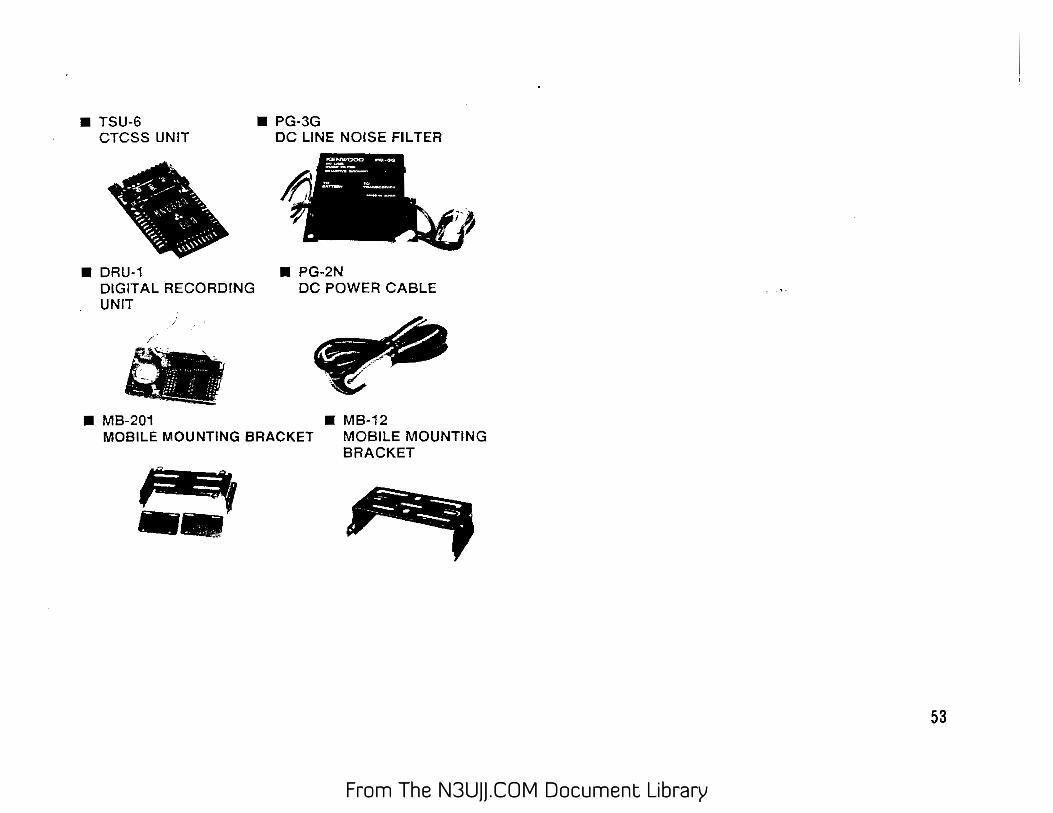
8. OPTIONAL ACCESSORIES . . . . . . . . . . . 52
3
From The N3UJJ.COM Document LibraryFrom The N3UJJ.COM Document Library
IAWIRIIIIIG[ BEFORE OPERATION
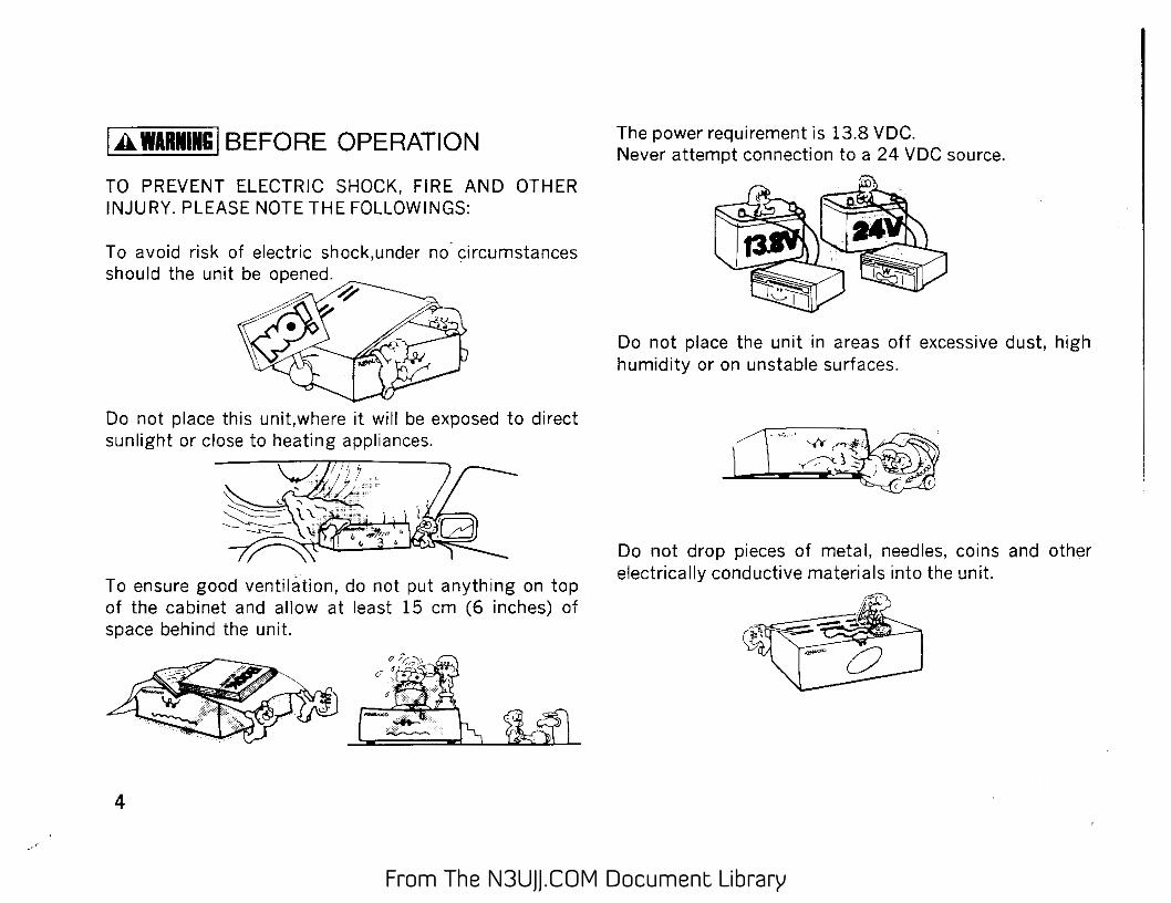
TO PREVENT ELECTRIC SHOCK, FIRE AND OTHER INJURY. PLEASE NOTE THE FOLLOWINGS:
Do not place this unit,where it will be exposed to direct sunlight or close to heating appliances.
Y?J;2t \\. ~-'~
~-- -~~-, "~~~..-::-'-+-'!
To ensure good ventilation, do not put anything on top of the cabinet and allow at least 15 em (6 inches) of space behind the unit.
4
The power requirement is 13.8 VDC. Never attempt connection to a 24 VDC source.
Do not place the unit in areas off excessive dust, high humidity or on unstable surfaces.
Do not drop pieces of metal, needles, coins and other electrically conductive materials into the unit.
From The N3UJJ.COM Document LibraryFrom The N3UJJ.COM Document Library
Do not touch the power plug, when your hands are wet.
Do not pull the power cord, when disconnecting it from the AC wall outlet. Grasp the plug and ensure that your fingers do not touch the live pins.
If an abnormal odor or smoke is detected, immediately turn the power oft and pull out the power plug. Contact the KENWOOD service station or our dealer.
CLEANING 1. Turn the power off, before cleaning the unit. 2. Do not use any type of abrasive pad, thinner,
benzine or any substances which may damage the unit.
3. Wipe the front panel and other exterior surfaces of the unit with a soft dry cloth or a soft cloth lightly moistened with water.
5
From The N3UJJ.COM Document LibraryFrom The N3UJJ.COM Document Library
2 SPECIFICATIONS TM-241A/E l TM-44iA,~~AIC"""~ I ___ --:--:T:-cMc---44_1-c-A:-cc--+--:--::T-:-M_-44---,l ..... E-:-f---:T ..... M-:-·54_1_A/'-E--I
F re<"• '"n"''- range M:.:_H:..cz=---------+---=1...:.4...:.4...ct:.::.o..::.1:...:4:.::.8_]_1--'-4--'4--'to'--14-=6...:.'_J_...:.4:.::.3.::.8...:.to=---450=::-:,-==! :-:4-=3:..:0...:.t:.::.o_440_:.::.__L_4-'--3"-'0:_:.:to...:.440......::_]__:1:.::2:..:.40.::.:.::.to:_:.:l300::.::.::-l Mode F3E(FM)
TM~241 AIU.S,..\/Canaoa)
i Antenna impedance 5Cn f----~'-'----------+--------------~-~c--c------~-----:-,----------------1
Operating temperature -2o·c to +60~C (-4"Fto + 140"F)
e Power requirements 13.8V DC ±15%(11.7-15.8V) ~ Ground ID f-------,---------
0
Negative
Current drain f--T_r_a_n_sm ___ it_m ___ o __ d __ e_-+-------Le __ s_s_th_a_n_l_l_A _____ j ______ L_es ..... s_th_a_n_l_O_A _____ _._I_L_ess_th_a_n_6_A------< Receiver mode Less than 0.6A
Frequency stability ___ Less than ±lOppm I Lessthan±3ppmi ~Di:..:rre-=n.::.sio::.:n.:.:s "":w::=x-=H=X:.::D:.::.) oC.[m-M-:-) -::e:--ro.,-jec-ct-,on-s ..... in-:cl-udc--ed::--) ---+---,1-:4:-::0-X-,4:-::0-x-,1-=6·0::-(5-li2" x l-37/64"X 6-19/64") (140 X 40 x 172(5-1/2"X 1-37/64'" X6-25/32") , ,-w-eigh-t_---'-----'---'---:(7-'kg'-:)-"-------'---t--'---'-----'-'----'-----'-...:....:.--...:... ___ 1.2(2.651bs) --~
--~----+-----------------'---------------------1 ~ Spurious radiation Less than - 60 dB "'
Output power 2
~ Maximum frequency~de:_:vc:.:ia=t.:.:io"-'n--:--:--:--+------------.,---..,.,---::-::=+=-5K==-:Hz..::::.,--:::-::-::-::-:-c---:------------l Audio distortion (at 60% modulation) Less than 3% (300 to 3000 Hz)
Microphone impedance 6()(Xl
Circuity Double conversion superheterodyne Intermediate frequency 1st/2nd 30.825MHzi4S5kHz • 107MHll455kHz 30.825MHz I 455kHz 59.7MHz/455kHz
~ : Sensitivity (12 d_B:..S:..I:..N:..A=D"-) ------+=L"-es:.:.s:..th:..a...:.n...:.0:..:2:..5·"::..:V:..L i. --:::-=-:-::--,.,--L=e:.::s:..s c-=:th:cca:..n:..0.:.·-=:16:=::-c~-'':::V--:-_--:-_--::--:~-:--------I ., ! Selectivity -6dB: More than 12 kHz -60dB Less than 24 kHz u
&:: i Squelch sensitivity Less than 0.1 ,uV Less than 0.177 ,uV Less than 0.1 !-' V i Output (5% distortion) More than 2 W across 8 n loads
i External speaker impedance 8fl L............L:=---:c-,~:.:..:..c=--...:...c..~:.:::.:c--=-=---~~----'--------~~-----------=-=---------------'
6 Circuits and ratings are subject to change without notice due to advancement in technology.
From The N3UJJ.COM Document LibraryFrom The N3UJJ.COM Document Library
3 ACCESSORIES Unpack your new transceiver carefully, and examine it for visible damage If the equipment has been damaged in shipment, notify the transportation company immediately. Save the boxes and packing material for future shipping. The following accessories should be included in the box with the transceiver.
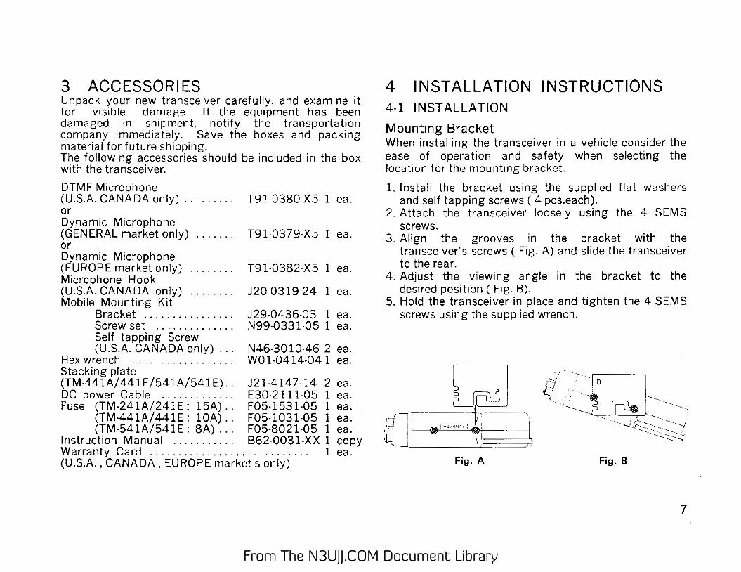
Mounting Bracket When installing the transceiver in a vehiclie consider the ease of operation and safety when selecting the location for the mounting bracket.
1. Install the bracket using the suppliecl flat washers and self tapping screws ( 4 pcs.each).
2. Attach the transceiver loosely using the 4 SEMS screws.
3. Align the grooves in the bracket with the transceiver's screws (Fig. A) and slide the transceiver to the rear.
4. Adjust the viewing angle in the bracket to the desired position ( Fig. B).
5. Hold the transceiver in place and tighten the 4 SEMS screws using the supplied wrench.
Fig. A
7
From The N3UJJ.COM Document LibraryFrom The N3UJJ.COM Document Library
4-2 4-2-1
CONNECTION Mobile Installations
utions : 1. Before installing the power cable, be sure to
remove the negative lead from the battery for safety.
'2. After installation and wiring, be sure to double I check for correct installation before reconnecting .
the negative lead to the battery terminal. · 3. If the fuse opens, be sure to check that each
conductor has not been damaged by short . circuiting, etc. Then replace with a new fuse of the same rating.
4. After completing the wiring, wrap the fuse holder with heat resistant tape to protect against heat and moisture.
5. Do not remove the fuse even if the power cable is too long.
A. Battery Connechons
Connect the power cable directly to the battery terminals. Using of the cigarette lighter socket will lead to a poor connection, and will result in poor performance. Pay close attention to the polarity of the cables when connecting them to the battery.
a
Make sure the positive i +I and negative (-)lead polarity when connecting to the battery.
Engine compartment --JL-- Passenger co. mpartment R~d Fuse L.:J I
• Black \ To the
, \ transceiver
Fuse {'>
rs;;;;~··~'tlon _whtne 'i I th& ;x>wer cttbls j$ pro' !acted ftom hflat. tru>JS: lUri;~ 0' abr<»ion when
1 se<:unng trm cabfe
CjJ -::,<s~.:::.;=" "::I ~ I eQge of the hole bv using l : ;l grommet,
Chassis or "------ ··-~~~ fire wall
• If the wiring hole in the fire wall or chassis is too small, disassemble the fuse holder to thread the wire through the hole.
B. Ignition Noise
From passenger
...;cll::om=p=a=rt::m::en=t (B'Il Thread like this
This transceiver has been designed to suppress ignition noise; however, if excessive noise is present, it may be necessary to use suppressor spark plugs (with resistors)-
From The N3UJJ.COM Document LibraryFrom The N3UJJ.COM Document Library
4-2-2 Fixed Station
A regulated DC power supply (13.8 VDC capable of supplying at least 11 amperes) is required. PS-33 is recommended.
1. Never connect the AC power cable to the AC outlet until all other connections have been made.
2. Before connecting and disconnecting the power connector. be sure to turn OFF the POWER · switches of both the transceiver and the DC 1
power supply. • 3. Observe polarity of the DC power cable. The
transceiver operates on 13.8 VDC, negative ground. Battery polarity must be correct. The power cable is color coded:
Red --" + (Positive polarity) Black ---. - (Negative polarity)
4-2-3 Antenna
The type of antenna that is used will greatly affect the performance of the transceiver. Use a properly adjusted antenna, of good quality, to enable your transceiver to perform at its best. The antenna input impedance is 50 ohms. Use 50-ohm coaxial cable such as RG-8U or 80-2V for this connection. If the antenna is far from the transceiver the use of low loss coaxial cable, such as RG-8U is recommended. Match the impedance of the coaxial cable and that of the antenna so that the SWR is less than 1.5 to 1. The protection circuit in the transceiver will activate if the SWR is particularly poor (greater than 3 to 1). High SWR values will cause the transmitter output to drop, and may lead to TVI or BCI reports.
Caution : We recommend that you install a high quality lightening arrestor in your antenna lines for protection against fire,electric shock,personal injury,or damage to the radio itself.
9
From The N3UJJ.COM Document LibraryFrom The N3UJJ.COM Document Library
5 OPERATION 5-1-1 CONTROL FUNCTIONS
A.LDCK - - REV
CD POWER switch Press to turn the transceiver on or off. Press the VFO/M ~ V or M R/M key and switching the power on will reset the VFO or MEMORY. The microphone PF key can be programmed when the power is switched on.
·~Tuning control This control is used to select the desired transmitter I receiver frequency, M Hz step, memory channel, frequency step, tone frequency, scan direction, etc.
@VOL control This control is used to adjust the volume from the internal and external speaker (if used). Clockwise rotation will increase the volume and counterclockwise rotation will decrease the volume.
@ SQL (Squelch) control
10
This control is used to select the desired squelch threshold level.
:ID LOW /01 M key LOW
I~
This function is used to select the !transmit output power level (HI, MID(Except TM-54V\/E), or LOW). DIM This function is used to select the intensity of the front panel display illumination. (See page 48) Pressing the F key for longer than 1 second and then press the LOW/DIM key while the F indicator is flash· ing will turn the time-out timer function on and off.
@Microphone connector Attach the supplied microphone to this connector. The pin out of the connector is shown in the accompanying illustration.
])GND---, :I'· MIC
(Microphone Audioi'-.A~~
J_', PTT (Push to Talk)
(j) GNO {Microphone audial
([l RX Audio Output (Approx 100 mV/10 k ohm)
-?) 8 VOC (Max 1 SO mAl
From The N3UJJ.COM Document LibraryFrom The N3UJJ.COM Document Library
CD VFO/M Ill> V key This key is used to return to VFO operation after operating in the MR or CALL channel mode. Pressing this key will allow the tuning control and microphone UP /OWN keys to increase or decrease the operating frequency.
Press and hold the key for longer than 1 second to initiate VFO scan. Pressing the key after scan has been initiated will cause scan to stop.
Pressing the key within 10 seconds of pressing the F key will copy the memory channel or caU channel data to the VFO .. This allows you to change parameters of that channel without actually changing the data that has been stored in memory.
Pressing the F t\ey for longer than 1 second and then pressing the VFO key will cause radio to toggle the hold I resume mode between Time Operated scan and Carrier Operated scan.
If you press and hold the VFO key while you turn on the POWER switch you will reset the microprocessor's VFO memory, without destroying the memory channel or call channel data.
@ MR/M key This key is used to select MR (Memory Recall) mode from the VFO mode. The tuning control can then be used to select the desired Memory channel.
Pressing the key for longer than 1 second will initiate memory channel scanning.
Pressing tl1e key within 10 seconds of pressing the F key will store the displayed data into memory. In the MR channel mode pressing the F key for longer than 1 second and then pressing the MR key will cause the Memory channel to skip during Memory channel scan mode.
If you hold and press this key while you turn on the POWER switch you will clear all the microprocessor's operator programmed memory section.
MHz/LOCK key This key is used to tell the microprocessor that you wish to increase or decrease the operating frequency in 1 MHz increments.
Pressing this key within 10 seconds of pressing the F key will cause the key lock function to activate, protecting the currently displayed data from accidental erasure.
Pressing the F key for longer than 1 s'econd and then pressing MHz I LOCK key while the F indicator is flashing will turn the AUTOMATIC POWER OFF function on or off.(See page 48)
11
From The N3UJJ.COM Document LibraryFrom The N3UJJ.COM Document Library
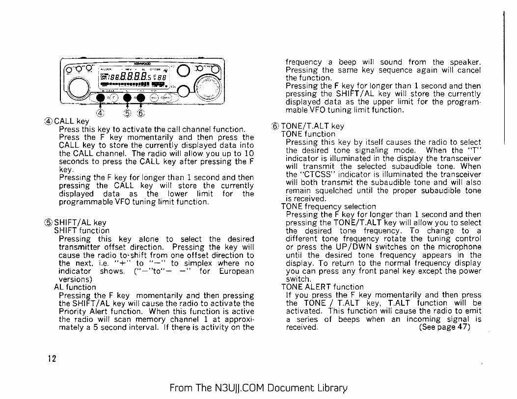
@CALL key Press this key to activate the call channel function. Press the F key momentarily and then press the CALL key to store the currently displayed data into the CALL channel. The radio will allow you up to 10 seconds to press the CALL key after pressing the F key. Pressing the F key for longer than 1 second and then pressing the CALL key will store the currently displayed data as the lower limit for the programmable VFO tuning limit function.
(WSHIFT/AL key SHIFT function
Pressing this key alone to select the desired transmitter offset direction. Pressing the key will cause the radio to·shift from one offset direction to the next. i.e. " " to "-" to simplex where no indicator shows. ("-"to"- -" for European versions)
AL function
12
Pressing the F key momentarily and then pressing the SHIFT I AL key will cause the radio to activate the Priority Alert function. When this function is active the radio will scan memory channel 1 at approxi· mately a 5 second interval. If there is activity on the
frequency a beep will sound from the speaker. Pressing the same key sequence again will cancel the function. Pressing the F key for longer than 1 second and then pressing the SHIFT I AL key will store the currently displayed data as the upper limit for the program· mabie VFO tuning limit function.
:§) TONE/T.AL T key TONE function
Pressing this key by itself causes the radio to select the desired tone signaling mode. When the "T" indicator is illuminated in the display the transceiver will transmit the selected subaudible tone. When the "CTCSS" indicator is illuminated the transceiver will both transmit the subaudible tone and will also remain squelched until the proper subaudible tone is received.
TONE frequency selection Pressing the F key for longer than 1 second and then pressing the TON E/T.AL T key will allow you to select the desired tone frequency. To change to a different tone frequency rotate the tuning control or press the UP /OWN switches on the microphone until the desired tone frequency appears in the display. To return to the normal frequency display you can press any front panel key except the power switch.
TONE ALERT function If you press the F key momentarily and then press the TONE / T.AL T key, T.AL T function will be activated. This function wili cause the radio to emit a series of beeps when an incoming signal is received. (See page 47)
From The N3UJJ.COM Document LibraryFrom The N3UJJ.COM Document Library
r?; REV /STEP key This key is used to reverse the transmit I receive frequencies during repeater operation. If you have selected simplex this key will not function! Pressing the F key momentarily and then the REV /STEP key will allow you to select the desired VFO tuning step and Scan step size. Use the tuning control to select the desired tuning step and then press any front panel key except the POWER switch to return to the normal frequency display. Pressing the F key for longer than 1 second and then pressing the REV/ STEP key will turn the BEEP function Off or ON.
® DR/DT/AL T key(AL T: TM-541A/541E only) DR/DT function · ..
Pressing this key aione to select the DTSS(Dual Tone Squelch System) function or DRS (Digital Recording System ) function.
AL T function Pressing the F key momentarily and then the DRIDT I AL T key will cause the AL T(Automatic Lock Tuning) function of the TM-541AI541 E to activate. Pressing the F key for longer than 1 second and then pressing the DT I DR I AL T key will turn the DRS function ON or OFF.
A.LOCK On when the All Lock function has been activated.
@ DTSS
@DRS
@ APO
On when the Automatic Lock Tuning function is active. When the AL T system is operating the direction indicator will turn on if the system shifts the receiver frequency. On when the DTSS function has been activated. On when the Digital Recording System is active. On when the Automatic Power Off function has been activated. On when the squelch opens.
(J) '''"~"'~'~'!!'!'~!!Ill This level meter indicates the rela·
'~' LOW MID
ON AIR
tive receiver signal strength or the relative transmitter power output. Indicates the relative output power setting for transmit. No indicator for high pow~~r. On when the Time Out Timer function has been activated. On during transmit.
13
From The N3UJJ.COM Document LibraryFrom The N3UJJ.COM Document Library
I I
rl.}:CTCSS
Indicates the active memory channel number. * indicates that the chan· nel is locked out. Cis displayed during call channel. Either PO, Pl, P2, P3, or PA is dis· played during paging. On whenever the F key has been de· pressed. Also shows the last memory channel number that had been se· lected. On when the Tone Alert function is active. The indicator flashes when signal has been received. On when the Tone Decode and En· code function has been activated.
c_ ____ On when the Tone Encode function
i5l AL
@REV
+
has been activated. On when the Priority Alert function has been activated. On when the Reverse function has been activated. Display the selected transmitter off· set direction. Both - and + light at the same time during split channel operation.
@ :aaB.BBBs Displays the operating frequency to
L_ the nearest kHz digit; or the tone frequency etc. The indicator flashes when scan· ning.
14
Q) ANTENNA connector Attach an antenna with a low SWR and an impedance of 50 ohms.
~ 13.8 VDC power input connector Connect the supplied DC power cable to this connector. Pay close attention to the polarity. Red is positive and black is negative.
@Fuse holder Contains a requaired fuse. TM-241A: 15A, TM-441A: lOA, TM-541A: SA Do not use a larger fuse as damage might result to the transceiver.
@External speaker jack This jack is used to connect an external speaker. The speaker should have an impedance of 8 ohms.
From The N3UJJ.COM Document LibraryFrom The N3UJJ.COM Document Library
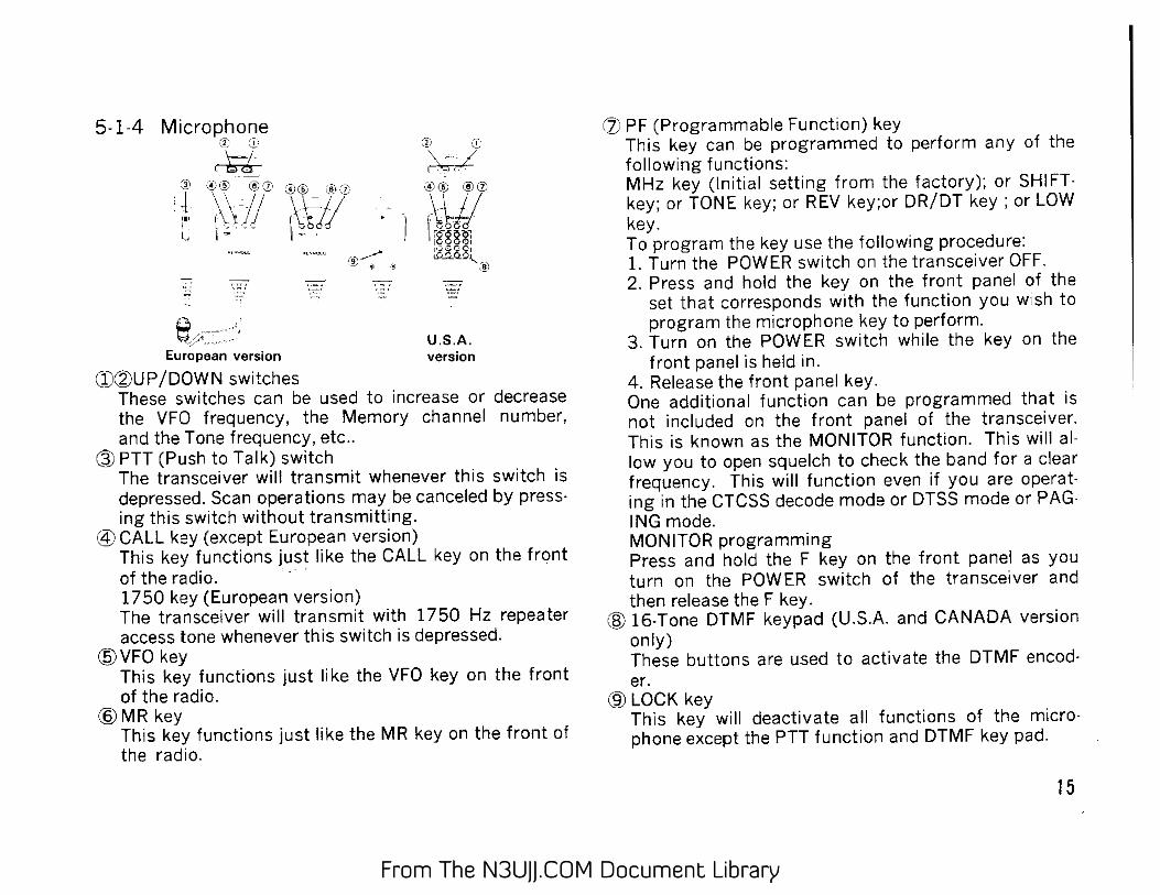
5-1-4 Microphone ,~f. ,,,
\-.7 ci:!O
U.S.A. European version version
CD®UP/DOWN switches These switches can be used to increase or decrease the VFO frequency, the Memory channel number, and the Tone frequency, etc ..
@ PTT (Push to Talk) switch The transceiver will transmit whenever this switch is depressed. Scan operations may be canceled by pressing this switch without transmitting.
@CALL key (except European version) This key functions just like the CALL key on the front of the radio. · 1750 key (European version) The transceiver will transmit with 1750 Hz repeater access tone whenever this switch is depressed.
@VFO key This key functions just like the VFO key on the front of the radio.
@MR key This key functions just like the MR key on the front of the racio.
(}) PF (Programmable Function) key This key can be programmed to perform any of the following functions: MHz key (Initial setting from the factory); or SHIFT· key; or TONE key; or REV key;or DR/DT key; or LOW key. To program the key use the following procedure: 1. Turn the POWER switch on the transceiver OFF. 2. Press and hold the key on the front panel of the
set that corresponds with the function you wish to program the microphone key to perform.
3. Turn on the POWER switch while the key on the front panel is held in.
4. Release the front panel key. One additional function can be programmed that is not included on the front panel of the transceiver. This is known as the MONITOR function. This will allow you to open squelch to check the band for a clear frequency. This will function even if you are operating in the CTCSS decode mode or DTSS mode or PAGING mode. MONITOR programming Press and hold the F key on the front panel as you turn on the POWER switch of the transceiver and then release the F key.
@ 16-Tone DTMF keypad (U.S.A. and CANADA version only) These buttons are used to activate the DTMF encod· er.
@LOCK key This key will deactivate all functions of the microphone except the PTT function and DTMF key pad.
15
From The N3UJJ.COM Document LibraryFrom The N3UJJ.COM Document Library
5-2 RECEIVER OPERATIONS Audio confirmation is provided whenever a front panel key is depressed. You can disable this function by pressing the F key for longer than 1 second and then pressing the REV/STEP key.
5·2·1 Receptoin
1. Connect the power supply, antenna, and microphone and then adjust the controls as follows:
Power Switch . . . . . . . . OFF Vol Control . . . . . . . . Full Counterclockwise Power switch of power supply (Fixed station) . . . . . . OFF SQL Control . . . . . . . . Full Counterclockwise
2. Turn on the Power Supply and then turn on the transceivers POWER switch. The display should indicate a frequency. Fig.l shows examples of frequencies that will appear on the various models. In addition to the frequency you may see one or more controlrndicators illuminats on the display.
TM-441A
16
TM-241 A/241 E 'lU .S.J).:.'I.ersion) TM-541 A/541 E
~~a.aaa - . -·--·-·--·-
TM441 A/TM-441 E
Fig. 1
,,unnan rc,U.U U
Note The frequencies shown above are the default frequencies after a microprocessor reset. If the
: :
i display shows incomplete data or you think the :displayed frequency is in error you should reset the I Microprocessor. Memory Initialization on page 21.
.J
3. Rotate the VOL control clockwise until a signal or noise is heard coming from the speaker.
4. Rotate the tuning control or press the microphone UP/OWN switches to select an open channel. Then rotate the SQL control clockwise until the noise just disappears and the BUSY indicator turns off. This point is known as the Squelch Threshold point. The squelch control must be adjusted to this setting for the Scan functions to operate properly.
5. Select the desired operating frequency using the microphone or tuning control. When a signal is received the S-meter will deflect and the BUSY indicator will turn ON.
Caution Turn off the transceivers POWER switch before you start or stop your vehicles engine. or your home
. power supply.
From The N3UJJ.COM Document LibraryFrom The N3UJJ.COM Document Library
5-2-2 Frequency Selection
You can change the dial frequency while in the VFO mode. The frequency can then also be stored in memory, or in the call channel using the techniques that will be described in this manual.
---- -----~---VFO rnode
MR key VFO key VFO key CALL key
[MEMORY cha_nnel mode •
CALL key
MR key
e VFO Mode Operation FrE~quency Selection 1. Press the VFO/M ~ V key to select the VFO mode. 2. Rotate the tuning control or press the microphone
UP /DWN switches to select the desired frequency. e Memory Channel Selection 1. Press the MR/M key. 2. Rotate the tuning control or press the microphone
UP I DWN switches to select the desired memory channel.
e CALL Channel Selection Press the CALL key to select the Call channel.
5-2-3 Frequency Step Selection
The frequency step is indicated in the chart below. STEP
5~ 1 0~ 15~20~ 12.5~25
TM-241A/E (J (J (J (J (J (J
TM-441A/E (J (J (J 0 (J (J ~----f-~
TM-541A/E X (J X (J (J (J
To select the desired tuning or scan step size use the following procedure: 1. Press the VFO/M ~ V key to select the VFO mode. 2. Press the F key momentarily. The F indicator should
light in the display. 3. Press the REV /STEP key within 10 seconds of pressing
the F key. The current frequency step size will be displayed.
17
From The N3UJJ.COM Document LibraryFrom The N3UJJ.COM Document Library
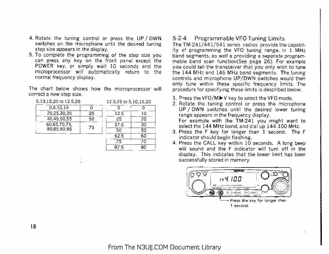
4. Rotate the tuning control or press the UP I DWN switches on the microphone until the des1red tuning step size appears in the display.
5. To complete the programming of the step size you can press any key on the front panel except the POWER key, or simply wait 10 seconds and the microprocessor will automatically return to the normal frequency display.
The chart below shows how the microprocessor will correct a new step size.
5,10,15,20 to 12.5,25 12.5,25 to 5,10,15,20
R.5.10.15 ··~~ -.,..oa····--: 6,25,30,35 i 25
'-----:::io-C:,4:is-':::.so.ss ~- so
I
. 6o,65,7o,75, 75
I . 80,85,90,95 .J
0 0 ~ ,_ ... ··-i 12.5 10 f---·-·······
__ .. _
I 25 20 I 37.5 30
50 50 62.5
' 60 I 75
. ' 70
I 87.5 I 80
18
5-2-4 Programmable VFO Tuning Umits The TM-2411 4411541 series radios provide the capabil· ity of programming the VFO tuning range, in 1 MHz band segments, as well a providing a separate program· mabie band scan function(See page 26). For example you could tell the transceiver that you only wish to tune the 144 MHz and 145 MHz band segments. The tuning controls and microphone UPIDWN switches would then only tune within these specific frequency limits. The procedure for specifying these limits is described below.
1. Press the VFOIM..,V key to select the VFO mode. 2. Rotate the tuning control or press the microphone
UP I DWN switches until the desired lower tuning range appears in the frequency display. For example with the TM-241 you might want to select the 144 MHz band. and dial up 144.100 MHz.
3. Press the F key for longer than 1 second. The F indicator should begin flashmg.
4. Press the CALL key within 10 seconds. A long beep will sound and the F indicator will turn off in the display. This indicates that the lower limit has been successfully stored in memory.
Press the key for longer than 1 second.
From The N3UJJ.COM Document LibraryFrom The N3UJJ.COM Document Library
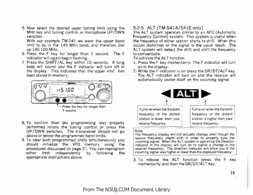
5. Now select the desired upper tuning limit using the MHz key and tuning control, or microphone UP/OWN switches. With our example TM·241 we want the upper band limit to be in the 145 MHz band, and therefore dial up 145.100 MHz.
6. Press the F key for longer than 1 second. The F indicator will again begin flashing.
7. Press the SHIFT/AL key within 10 seconds. A long beep will sound and the F indicator will turn off in the display. Thiis indicates that the upper limit has been stored in memory.
8. To confirm that the programming was properly performed rotate the tuning control or press the UP /OWN switches. The transceiver should not go above or below the programmed band limits.
9. To clear both pr.ogrammed limits simultaneously you should initialize the VFO memory usmg the procedures discussed on page 21. You can reprogram either limit independently by following the appropriate instructions above.
5·2·5 AL T (TM-541A/541 E only) The AL T system operates similar to an AFC (Automatic Frequency Control) system. This system is useful when the frequency of either station starts to drift. When this occurs distortion of the signal is the usual result. The AL T system will detect the drift and shift the frequency to compensate. To activate the AL T function 1. Press the F key momentarily. The F indicator will turn
on in the display. 2. While the F indicator is on press the DR/DT I AL T key.
The AL T indicator will turn on and the receiver will automatically center itself on the incoming signal.
Turns on wh·en the transmit , frequency of the distant i
, station is lower than your I Lre~eive fr!l(l!Jency. . ...... .
Note:
Turns on ~hen the transmit I frequency of the distant I
station is higher than your [ receive frequency.
, The frequency display will not actually change, even though the ' receive frequency might shift in order to properly tune the · incoming signal. When the AL T system is operating the Direction • indicator in tho~ display will turn on to signal a change in the i receiver frequency. The direction indicator will show you if the I incoming signa I was higher or lower than the displayed frequency.
. .. -
3. To release the AL T function press the F key momentarily and then the DR/DT I AL T key.
19
From The N3UJJ.COM Document LibraryFrom The N3UJJ.COM Document Library
5-3 TRANSMITTER OPERATION
Caution 1. Ensure that an antenna with a low standing wave !
ratio (SWR) is attached to the antenna connector . before attempting to transmit. Failure to provide : proper termination may result in damage to the i
final amplifier section. · 2 Always check to ensure the frequency is clear
before transmitting.
r--··· ... .. ----· :Note t I The .use of LOW power is recommended whenever \
oss1ble, to avoid interfering with other stations. !
5-3-1 Transmit Basics 1. Select the desired operating frequency using any of
the methods previously discussed. 2. Press the LOW /DIM key to select the desired transmit
output. . ·
~--.. ~ ·Q;B'"Ol_ -~ I :'15.5[][] I . I
~o I - -·-·-·-·-·--- - ! .. "- ______,>~-,,._ 4-' AC '"'-' , ...
20
3. Check the frequency to see if it is occupied before you transmit.
4. Press the PTT switch. The ON AIR indicator will light, and the RF meter will deflect to the right. If you have selected the LOW power position, the low indicator will appear in the display and the RF meter will only deflect slightly. When HI power has been selected the RF meter will deflect full scale.
5. Speak into the microphone. The recommended distance to the microphone is 5 em (2 inches).
5-3-2 Time-out Timer (TOT) The TOT can limit the continuous transmission time to 30 minutes. 1. Press the F key for longer than 1 second, then press
the LOW/DIM key. The T indicator will light. To cancel the setting, repeat the operation.
Press the key for longer than 1 second.
2. When the time-out timer reaches the transmission time limit, a beep will sound and the transceiver will return to the receive mode. To transmit again, release the PTT switch and press it again.
From The N3UJJ.COM Document LibraryFrom The N3UJJ.COM Document Library
5-4 MEMORY 5-4-1 Microprocessor Memory Back-up This transceiver contains a lithium battery to retain memory. Turning off the POWER switch, disconnecting the power cable, or a power failure will not erase the memory.The battery should last for approximately five years. When the battery discharges, an erroneous display may appear in the display. Lithium battery replacement should be performed by an authorized KENWOOD service facility; either your authorized KENWOOD dealer or authorized service center.
5-4-2 Initial State Initial state of the microprocessor from the factory is shown in the chart below ...
. TM-241A/E I TM-441A/E TM-541A/E -
VFO, Memory 144.000
440.000/ ! 1240.000 i ' channel 1, CALL ! 430.000
channel frequency MHz
MHz
VFO step l 5/12.5kHz 25kHz
1 Memory channel lCH . lCH
·--·-···
! Tone frequency 88.5Hz 88.5Hz
5-4-3 Microprocessor Initialization e Memory channel Initialization
l
l MHz
25kHz
I lCH 88.5Hz ·-·---
When you want to erase all programed data, or if the display shows erroneous information, you should initialize (reset) the microprocessor using the following procedure.
1. Turn the POWER switch off.
I '
2. Press and hold the MR/M key and turn on the POWER switch.
3. Release the MR/M key.
e VFO Initialization All the settings, except the contents of the memory and call channels, are initialized.
1. Turn the power switch off. 2. Press and Hold the
VFO/M..,._V key then turn the power switch on. No transmit/ receive operation occurs when this is done.
r-·~
A LOCK - - P!EV "' AL CTCGS ~
~ [Rr.2'-/ / ';88
~~~~·~·~··~···~··~ ~p 3. Press the VFO/M ..,._ V key again.
5-4-4 Memory Channel This transceiver provides 20 Memory Channels. (18 Memory Channels when DRU-1 installed) In addition to serving as a normal Memory Channel some of the Memory Channels serve a dual purpose to specify other parameters. The functions of those Memory Channels are described below . C Memory Channel 1 is used to store the frequency for
the Priority Alert function. C) Memory Channel 7 ~ 10 are used to store odd split
repeater data. C) Memory Channel 11 is used to store the lower limit
for the Programmable Band Scan function. C) Memory Channel 12 is used to store the upper limit
for the Programmable Band Scan function
21
From The N3UJJ.COM Document LibraryFrom The N3UJJ.COM Document Library
5-4-5 Memory Contents
Each Memory channel is capable of storing the following information. eYES :Can be stored in memory, NO : Cannot be stored in memory)
When the DRS unit is not installed and the DTMF unit is installed.
~··----~----- ~ .. ·r • Freq.(SIMPLEX) YES . YES I
YES YES i f-f freq.(odd split) NO NO I YES I NO
..
: Tone freq. YES YES YES 1
YES Tone/CTCSS ON/OFF ! .
-···
VFO freq. step I YES YES . YES YES • ----.
• Shift, REV ON/OFF ~S ! YE_S_+i ___ N_O_-t
l DTSS cord, DTSS I YES I NO I NO NO
YES
ON/OFF ~---~•---~--~ When the DRS unit is installed and the DTMF unit is not installed r, ~~~~~-~~-------,---,---~
CHl-3 CH4~6. CH7-10 CHl~i
Freq.(SIMPLEX) 'fES YES YES YES ; freq.(odd split) NO NO YES NO I ~~-~-~-~---1---~--
1. Press the VFO/M~V key tor;;:;~:;===~~:::=:;: select the VFO mode. 1,
:'I 55/J [] 2. Select the desired operating frequency ,offset,tone frequency,etc.( For exam-ple 145. 50 0 M Hz ) ....__.:::::;.~..:.....;;;..:....;;..:....;;..:....;;..:.....;;'""
3. Press the F key. The F f':0;;.,0;;. .. ~g~:-~: ==~""""""~==;;
indicator and a memory -· · · :'I 5.5 [] [] F 8 . channel indicator will light.( For example CH 8)
4. Select the desired Memory G~~~==:iii~=~ Channel using the Tuning control or microphone UP/OWN switches. (For example CH 5)
1'/5.5 [] [] F 5
5. Press the MR/M key with in r:;~"'G;;· ~:7~"~'~'~. ::::::::::::::: .. ::: .. :J ......... ~c~: lOsecondsofselectingthe Q. ;-,r, •
55,, i
~e~~~ c;e~~ne~ill sound fQ'~ 1 -~ 1
'~.;~'-!.~. ... I. and the F indicator and the ~~~ ~3 "() (~ o8 8 "8 Memory Channel number will turn OFF, and the transceiver will return to the VFO mode.
From The N3UJJ.COM Document LibraryFrom The N3UJJ.COM Document Library
e Odd.Split Channels
1. Press the V F 0 I M .,. V key to ~~~~::=::::::==iii~:::::~ select the VFO mode. 1,
2. Select the desired receiv· ing frequency ,tone frequency,etc. (For example 145.600M Hz) '----'-~;......;;;;;......;;;;-=-=~
4. Select any Memory Chan· G~~~===:i~c~ nel from 7 thru 10 using the Tuning control or the microphone UP I OWN
:'15.6[][]
switches. (For example CH 10)
5. Press the MR/M key within~~~=,==:::::::~~=~ 10 seconds of selecting the a·o··g·· I -..co ]'"
AMem
1 ory Cbhannel. _
11 -o· . . . ·- -~~~:_6_~~- ,
ong eep w1 sound and the F indicator and the ..__...::::::;;.~8""":.;...· 0,;;.0.:....;;EJ.:..." .. _;;0 G;;;;;,·:;_8:.;;:·;:;...,""""8 Memory Channel number will turn OFF.
6. Within 10 seconds of press· ing the MR I M key, you should select the desired
transmit frequency using G~~~===:i~c~ the Tuning control or mi· crophone UP/OWN switches. (For example 145.700MHz)
. ..,5nnn • . IUU
7. Press the MR/M key within ~~~~===:i~c=;; 10 seconds of selecting the 1
' ''O"'Q""· " transmit frequency. A long
90" ; .. [ __ -~~~-~-~~ 1..
beep will sound to signal · - .. "" .... the data has been success- ..__ _ _...::::8 ...... _,0.;;;;'""""'"8'-· '..;;;8;;.,' ..;;;8;;;.· ...;;'8"-m fully stored.
8. To confirm the contents of ~~~~===:i-~c~ the Split Memory Channei 1'Q'"f!!'Q"'·
5 c;., n
press the MR/M key andre· o 1'1 .ouu :a call the channel. The re· ·- · · ·- · ..... '' CeiV!ng frequency and ~\.. 8 '0 EJ ,9 8 '8 - + indicator will appear in the display.
9. To check the transmit fre-r;~~~==:=i~c==::; ''CJ"(j"Q""· q uency press the REV /STEP ... · S n n n
key or Microphone PTT o 1" · •uu :a
~~~~:~cyTh~i II tr~~~~~~tini~ '=' '- e,0--6~;jf i ,e' the display.
23
From The N3UJJ.COM Document LibraryFrom The N3UJJ.COM Document Library
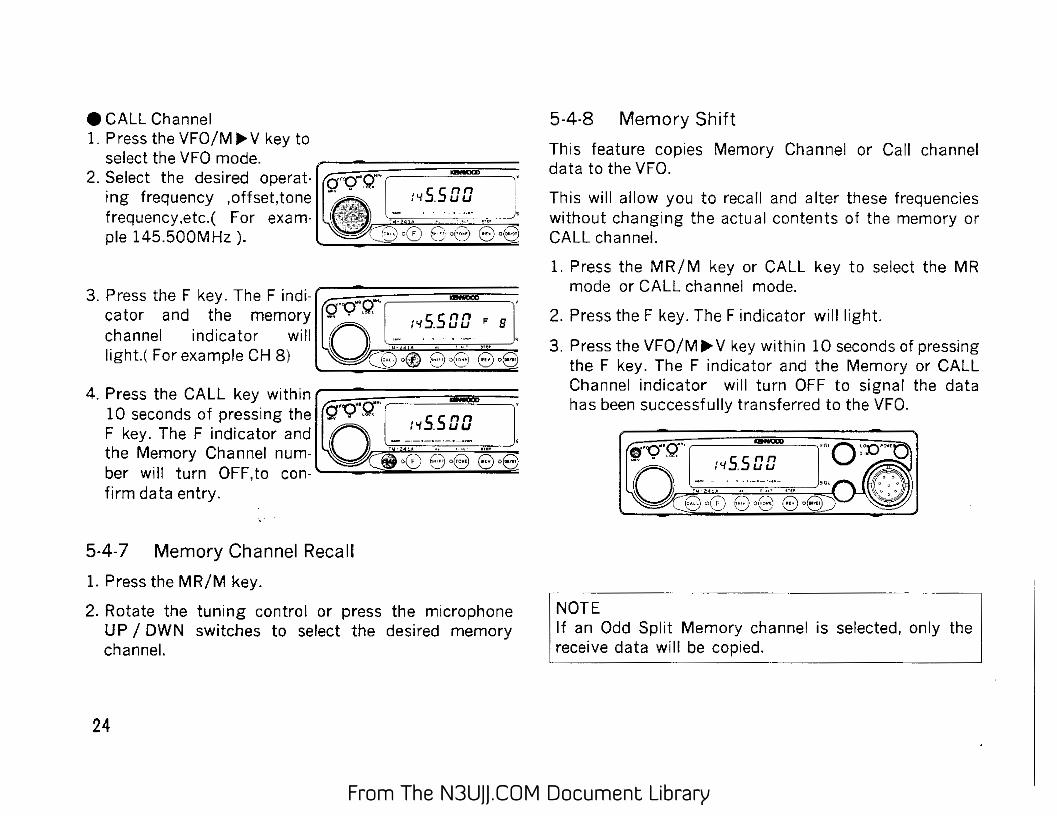
e CALL Channel 1. Press the VFO/M.., V key to
select the VFO mode. 2. Select the desired operat- ~;;;~~=:=::::::::::=i~c~
ing frequency ,offset,tone frequency,etc.( For exam· pie 145.500MHz ).
~~s.saa
the Memory Channel num- EH3 8o8 ber will turn OFF,to con-'--_;;:;;;.,...;;~_..;....,;;;;;;....;:-;..=.~
firm data entry.
5·4-7 Memory Channel Recall
1. Press the MR/M key.
2. Rotate the tuning control or press the microphone UP I DWN switches to select the desired memory channel.
24
5-4-8 Memory Shift
This feature copies Memory Channel or Call channel data to the VFO.
This will allow you to recall and alter these frequencies without changing the actual contents of the memory or CALL channel.
1. Press the MR/M key or CALL key to select the MR mode or CALL channel mode.
2. Press the F key. The F indicator will light.
3. Press the VFO/M..,. V key within 10 seconds of pressing the F key. The F indicator and the Memory or CALL Channel indicator will turn OFF to signal the data has been successfully transferred to the VFO.
NOTE If an Odd Split Memory channel is selected, only receive data will be copied.
From The N3UJJ.COM Document LibraryFrom The N3UJJ.COM Document Library
5-5 SCAN When the scan function is turned on, turn the tone alert function off. If the tone alert function is on, scan will not activate.
5-5-1 Scan Operation The following scan options are available:
1. Band scan Scan proceeds over the entire band( This function operates in the VFO mode only.).
2. Programmable band scan The scan frequency range is determined by the frequencies stored in Memory Channels 11 and 12 (This function operates in the VFO mode only.).
3. Memory channel scan Scan proceeds thfu those memory channels that actually have data entered and have not been locked out (This function operates in the Memory Channel mode only.).
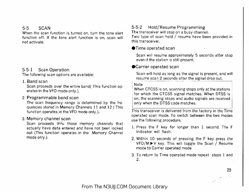
5-5-2 Hold/Resume Programming The transceiver will stop on a busy channel. Two type of scan hold I resume have been provided in this transceiver.
eTime operated scan
Scan will resume approximately 5 seconds after stop even if the station is still present.
ecarrier operated scan
Scan will hold as long as the signal is present, and will . resume S?~_n 2 se~()':cl_s after the signal c!T()P out.
Note :;;;! • When ?TCSS is on, scanning stops only at the stations :for wh1ch the CTCSS s1gnal matches. When DTSS is [on, the scanning stops and audio signals are received j only when the DTSS code matches.
This transceiver is delivered from the factory in the Time operated scan mode. To switch between the two modes use the following procedure.
1. Press the F key for longer than 1 second. The F indicator will flash.
2. Within 10 seconds of pressing the F key press the VFOIM II> V key. This will toggle the Scan I Resume mode to Carrier operated mode.
3. To return to Time operated mode repeat steps 1 and 2.
25
From The N3UJJ.COM Document LibraryFrom The N3UJJ.COM Document Library
5-5-3 Band Scan
1. Press the VFO/M Ill> V key to select the VFO mode.
2. Adjust the SQL control to the threshold point.
3. Press and hold the VFO i Mlii>V key for longer than 1 second. The MHz indicator will flash as a visual reminder the transceiver is scanning.
r-Press and hold the VFO I MIll> V key for longer 1 than 1 second.
Flashing
4. Scan will begin in an upward direction.You can reverse the direction by rotating the Tuning control counterclockwise, or by pressing the microphone DWN switch. The scan step size depends upon the current step programming.
5. Scan will stop whenever a signal is received (that activates the BUSY indicator) for a limited time.
6. Press the PTT switch or any front panel key to stop scan.
26
5-5-4 Programmable Band Scan 1. The lower scan limit must be stored in memory chan
nel 11 . The higher scan limit must be stored in mem· ory ch.:mnel 12. -~··· . . .
~~~~e: frequency in Memory Channel 11 is equal to~~r : :. greater than the frequency stored in Memory c~,annel 112 scan will proceed over the ent1re band Band ; Scan". 1
2. Adfu._s_t_t-he~SQL control to tile threshold point. ... 3. Press the VFO/ Mill> V key to select the VFO mode. 4. Select a VFO frequency between the two
programmed scan limits. 5. Press and hold the VFO I MIll> V key for longer than 1
second. The MHz indicator will flash as a visual reminder the transceiver is scanning.
Press and hold the VFO / MIll> V key for longer than 1 second.
Flasning 6. Scan will begin in an upward direction.You can
reverse the direction by rotating the Tuning control counterclockwise, or by pressing the microphone DWN switch.
7. Scan will stop whenever a signal is received (that activates the BUSY indicator) for a limited time.
8. Press the PTT switch or any front panel key to stop scanning.
From The N3UJJ.COM Document LibraryFrom The N3UJJ.COM Document Library
5-5-5 Memory Channel Scan
1. Adjust the SQL control to the threshold point. 2. Press and hold the MR/M key for longer than 1 sec
ond. The MHz indicator will flash as a visual reminder the transceiver is scanning.
Notes
Press and hold the MR/M key for longer than 1 second.
1. The transceiver will not scan it there is only one memory channeL
2. The transceiver will skip any locked-out channels. 3. The transceiver will scan only the memory channels in which
frequencies have been stored.
3. Scan will begin at. the current memory channel and proceed sequentially .i.e.M 1 __. M2 __. M3 etc. Only those memory channels with data entered are scanned.
4. Scan will stop whenever a signal is received ( that activates the BUSY indicator) for a limited time.
5. Press the PTT switch or any front panel key to stop scanning.
5-5-6 Memory Channel Lockout The Memory Channel Lockout function allows you to temporarily skip unwanted Memory Channels during Memory Channel scan. 1. Press the MR/M key to select the Memory Channel
mode. 2. Select the Memory Channel that you wish to skip by
using the Tuning control or the microphone UP/DWN switches.
3. Press the F key for longer than 1 second. The F indicator will flash. Within 10 seconds of pressing the F key press the MR/M key. A star C*) will appear to the left of the Memory Channel number . This indicates the Memory Channel will be skipped during the Memory Channel scan operation.,
Press the key for longer than 1 second.
4. Repeat steps 2 and 3 to lock out any other Memory Channel that you want to skip
5. To cancel the lockout , select the desired Memory Channels as described in step 1 ,2,and 3 above. The star (*) will go out. The Memory Channel will now be scanned normally.
27
From The N3UJJ.COM Document LibraryFrom The N3UJJ.COM Document Library
5-5-7 Priority Alert Function The priority alert function allows you to monitor memory channel 1 for activity even when you are tuned to a different channel number. When the Priority Alert function has been activated the microprocessor will switch the transceiver to the frequency stored in memory channel 1 once every 5 seconds. The transceiver will determine if a signal is present. If no signal is present the transceiver will return to the original frequency. If a signal is present, a beep will sound from the speaker to signal the channel is busy. This whole process takes just a fraction of a second, so you will not see the display frequency change. The only thing you will notice is a momentary pause in the signal on the currently dis· played frequency. To activate the priority alert function: 1. Ensure the frequency you wish to monitor has been
entered into memory channel 1. 2. Adjust the SQL control to the threshold point. 3. Press the F key momen-
tarily, and then press r:;;;;~;.=,=:=:::::i!~c=;:; the SHIFT I AL key. The gQ"'Q'"r-:-·· nn ----l" ~L indicator will turn on 00 ~'15.5uu 1n the d1splay to rem1nd . :-. -·-:-·-:::;-·- "" " you that this function EHD EH3 8•8 has been activated. · •
4. If a signal is present a beep will be heard from the speaker.
5. To turn this function off repeat step 3. The AL indi· tor will off.
. Note: During the period memory channel 1 is being scanned you will not -hear voice communications, only the beep will be heard if a present.
28
5-6 REPEATER OPERATIONS 5-6-1 Transmitter Offsets
All radio repeaters utilize a separate receive and trans· mit frequency. The receiver frequency may be either above or below that of the transmit frequency. The configuration of most repeaters will fall into one of the categories listed below: I ITM-241A/I TM-441A I TM441E TM541A l TM-54tE' : • 241E • European . : : ' !' , :1', version 1
, , i ; ~+600kHz-~1~+~5~M~H~z~-~~~l~_~67M~H7z--+~12~M~H7z-r+~3~5~M~H~z~.
E-::~-600 k~z,_ -5 MHz : =~:~=::-~~~~ -6 MHZ!
Offset Direction
To select the desired transmitter offset direction press the SHIFT I AL key. Each time you press the key the transceiver will advance from one direction to the next. i.e. " " to "-" ("-" to " -" with TM-441Eand TM-541A) to no offset (simplex).
Automatic Offset Selection (TM-241A U.S.A. version) The TM-241A has been programmed according to the standard ARRL (Amateur Radio Relay League) Band Plan with regard to transmitter offset direction. Please see the accompanying chart for addition information on this programming. You can, of course, override this by using the SHIFT I AL key if desired.
~_S ___ [ -mrs j_+m[ S I -m: +[~m· - ~m~--J S: simplex
From The N3UJJ.COM Document LibraryFrom The N3UJJ.COM Document Library
5-6-2 Reverse Function Some repeaters utilize a "Reverse Pair", i.e. the transmit I receive frequencies are exactly the reverse of another repeater. For example repeater A uses 146.000 for a transmit frequency (INPUT) and 146.600 for a receiver frequency (OUTPUT). Repeater B might use 146.600 for a transmit frequency and 146.000 for a receiver frequency. It would be inconvenient to have to reprogram the transceiver each time you wanted to use these repeaters. The REV /STEP key allows you to easily reverse the transmit and receive frequencies. To use the REV function press the REV /STEP key. The REV indicator will turn on in the display to remind you that you are working a reverse pair. To return to normal press the REV /STEP key again. The REV indicator will turn off. This function is also useful to check the input frequency of the repeater so that you can determine if you are within range for simplex communications.
5-6-3 Tone Operation Some repeaters require the use of a control signal to activate the repeater. Several different methods are currently in use. In the United States sub-audible tones are sometimes used. 38 different Sub-audible frequencies are possible. In Europe a 1750Hz tone is used in transmit. Press and hold the Microphone 1750 key to transmit with the access tone; you need not press the PTT key. Since this tone is required in Europe and the United Kingdom a 1750 Hz tone encoder is included with models delivered to these countries.
5-6·4 Tone Frequency Selection 1. Press the F key for longer than 1 second. The F indi
cator will begin to flash. Press the TONE/T.ALT key within 10 seconds of pressing the F key. The current tone frequency will show in the display.
Press the key for longer than 1 second.
2. Rotate the tuning control or press the microphone UP I DWN switches to select the desired tone frequency.
3. Press any front panel key to return to the normal frequency display.
Tone Frequency( Hz) i 67.0 107.2 . 167.9
71.9 110.9'~; i 73.8
. 77.0 118.8 • 186.2 79.7 i 123.0 i 192.8 82.5 127.3 203.5 I 85.4 Ll.OC371.78-t· .. -,2,-;1--;;;0-..7_-j 88.5 136.5 218.1
~?:1 14f.3 225.7. i 94.8 ~1""4"6". 2..-+--: "2-;:;-3 3;::-.-;::-6
1 ( 9 7.4! I 1,-;5;:-;1:-:.4:;-.,---;.2:;;:4-;;;1--;..8;,_-;;-1-;:::00"".;:-o -t---:1:-;:5,_6. ?!··· 250.3 ,
103.5 162.2 - . ~-.. ·~"~-
Note: 97.4 Hz is available only for encode.
29
From The N3UJJ.COM Document LibraryFrom The N3UJJ.COM Document Library
5-6-5 Autopatch Operations (U-S.A. versions only)
Some repeaters offer a service known as autopatch. This feature allows you to dial a telephone number from your transceiver and carry out a telephone conversion, much like a car telephone, or cellular telephone. This function requires the use of a DTMF (Dual Tone Multi Frequency) pad. The MC-44DM microphone provides the normal keys you would have on your telephone at home. as well as 4 additional keys. the A,B,C, and D keys. These keys are used for control operator of therepeater to see if they offer autopatch services.
To activate the keypad: 1. Press and hold the PTT key. 2. Press the keys just like you would dial your telephone
at home. 3. The transceiver will remain keyed for approximately
2 seconds after you press each number, so you can re· lease the PTT switch without unkeying the transceiver.
I Note: - .. J
I Some repeaters will require the use of a special key 1
·sequence to activate the Autopatch function. You •
I• should check with your control operator for this
1
.
1 sequence. --~---------
30
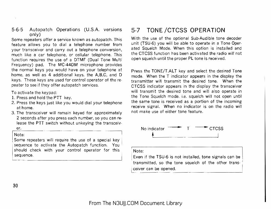
5-7 TONE /CTCSS OPERATION With the use of the optional Sub-Audible tone decoder unit (TSU-6) you will be able to operate in a Tone Operated Squelch Mode. When this option is installed and the CTCSS function has been activated the radio will not open squelch until the proper PL tone is received.
Press the TDNE/T.AL T key and select the desired Tone nnode. When the T indicator appears in the display the transmitter will transmit the desired tone. When the CTCSS indicator appears in the display the transceiver will transmit the desired tone and will also operate in the Tone Squelch mode. i.e. squelch will not open until the same tone is received as a portion of the incoming receive signal. When no indicator is on the radio will not make use of either tone feature.
No indicator T CTCSS
,------·· --------------, iNo~: I 1 lEven if the TSU-6 is not installed, tone signals can be
1
• transmitted, so the tone squelch of the other trans- I i ceiver can be opened. I L _______ _
From The N3UJJ.COM Document LibraryFrom The N3UJJ.COM Document Library
5-8 DTSS (Dual Tone Squelch System) OPERATION [Requires optional DTU-2]
This function allows squelch to be turned on in the receive mode on reception of a three-digit code matching the DTSS code selected in your radio. Once squelch is turned on by reception of a matching code, it operates normally from then on. If no signal is received for longer than 2 seconds, squelch is turned off until a matching code is again received. CTCSS signal cannot pass through the repeater, but DTSS signal can pass through the repeater.
NOTE • This function is not available in some areas. • The DTSS (or PAGIMG) cord may not be accepted if the I repeater is "identifying". If this should occur you should press ! the PTI switch again, and retransmit the DTSS (or PAGING) i cord. . There are two recommended methords of compensating for • this situation. ! 1. Press the PTI switch for a lew seconds, send the DTSS (or i PAGNG) cord, release the PTI switch, then press the PTT
switch again and resend the appropriate cord. i 2. Proper DTSS (or PAGING) operation will occur if you ensure · the battery saver circuit is disabled whenever you intend to i operate using eithr the DTSS or PAGING modes.
5-8·1 Selecting and Storing the DTSS code
DTSS codes from 000 through 999 can be selected from the VFO mode and stored in memory channels Memory channels 1 through 3 can each store a separate DTSS code.
Memory channels 4 to 20 and the call channel cannot store DTSS codes, but a DTSS code can be set each mode.
5-8-2 DTSS Code Selection
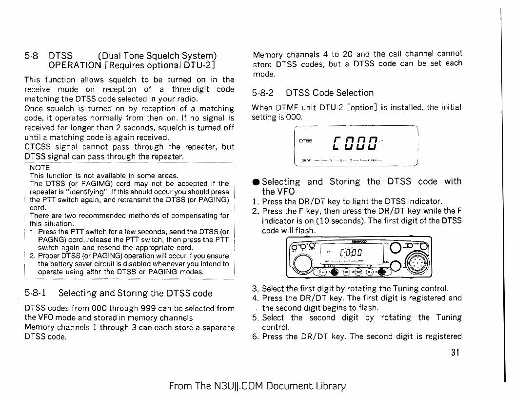
When DTMF unit DTU-2 [option] is installed, the initial setting is 000.
DTSS rnnn. I..UUU
e Selecting and Storing the DTSS code with the VFO
L Press the DR/DT key to light the DTSS indicator. 2. Press the F key, then press the DR/DT key while the F
indicator is on (10 seconds). The first digit of the DTSS code will flash.
3. Select the first digit by rotating the Tuning control. 4. Press the DR/DT key. The first digit is registered and
the second digit begins to flash. 5. Select the second digit by rotating the Tuning
control. 6. Press the DR/DT key. The second digit is registered
31
From The N3UJJ.COM Document LibraryFrom The N3UJJ.COM Document Library
and the third digit begins to flash. 7. Select the third digit by rotating the Tuning control. 8. Press the DR/DT key and the complete DTSS code is
registered. The mode returns to the previous one.
e Selecting and storing a code with the DTMF KEY PAD (MC-44DM)
1. Press the DR/DT key to light the DTSS indicator. 2. Press the F key, then press the DR/DT key while the F
indicator is on (10 seconds). The DTSS code setting mode will be entered and the first digit of the code will flash.
3. Then enter a three-digit number on the key pad.
........, Cf'Q"' g·· , • , """ "''""- r_n_n n
0.~·~ -_,_,~:'!~'-:_ -·~ .. ' "'' ....
/--..
fiii~: L~~~O. ·a~~~ a
5-8-3 Selection using memory channels 1 through 3
• Storing VFO frequencies and DTSS codes at the same time
L Select the desired frequency to be stored in memory in the VFO mode.
2. Follow steps 1 through 8 above in the VFO mode. 3. Press the F key 4. Select the desired memory channel (1, 2, or 3) with
the tuning control or the UP/DWN key on the microphone.
[ 55 nn , I !.I • (J f,J F 3 - - -·-·-·-·-·--
5. Press the MR/M key
~ e Rewriting DTSS codes in memory channels
Notes 1. If a key other than the DR I DT key on the front
pannel is pressed during operation, code selection mode is canceled.
2. If no action is taken for longer than 10 seconds, code selection mode is automatically canceled.
32
(1 to 3)
1. Press the F key while the memory channel is operat· ing, then press the DR/DT key while the F indicator is on. The DTSS code setting mode will be entered and the first digit of the code will flash.
2. Store the selected code in memory. Follow steps 1 through 8 in VFO mode to edit a stored code.
From The N3UJJ.COM Document LibraryFrom The N3UJJ.COM Document Library
5-8-4 Using the DTSS function
1. Adjust the SQL control to the threshold point
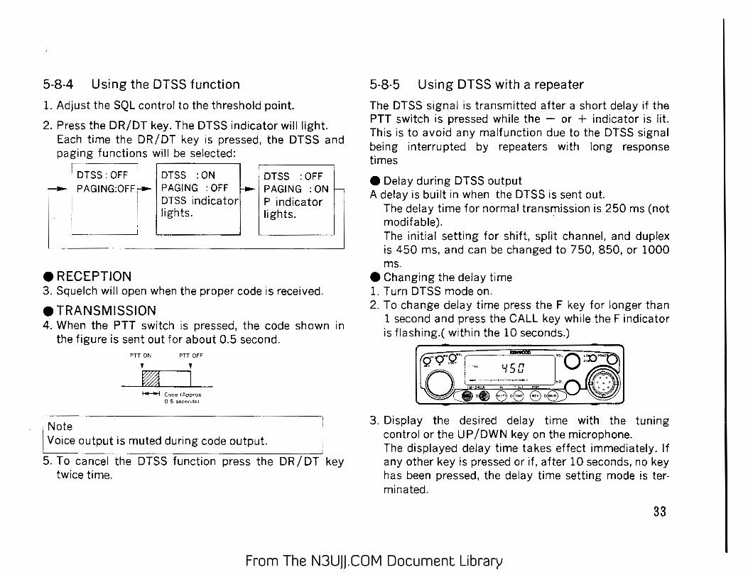
2. Press the DR/DT key. The DTSS indicator will light. Each time the DR/DT key is pressed, the DTSS and paging functions will be selected:
!orss : OFF I orss : oN :Or~s : oFF ! ,-I PAGING:OFF'- PAGING :OFF f--1 PAGING :ON~
DTSS indicator P indicator J. 1
L "•"''· ''•"''· d eRECEPTION 3. Squelch will open when the proper code is received.
e TRANSMISSION 4. When the PTT switch is pressed, the code shown in
the figure is sent out for about 0.5 second. PT1 ON PTT OFF
' ' ~ I ~ Code :Approx.
0 S s:ecc:;dsl
·Note I Voice outputi~ muted during code output.
5. To cancel the DTSS function press the DR/DT key twice time.
5-8-5 Using DTSS with a repeater
The DTSS signal is transmitted after a short delay if the PTT switch is pressed while the - or + indicator is lit. This is to avoid any malfunction due to the DTSS signal being interrupted by repeaters with long response times
e Delay during DTSS output A delay is built in when the DTSS is sent out
The delay time for normal transmission is 250 ms (not modifable). · The initial setting for shift, split channel, and duplex is 450 ms, and can be changed to 750, 850, or 1000 ms.
e Changing the delay time 1. Turn DTSS mode on. 2. To change delay time press the F key for longer than
1 second and press the CALL key while the F indicator is flashing.( within the 10 seconds.)
3. Display the desired delay time with the tuning control or the UP /OWN key on the microphone. The displayed delay time takes effect immediately. If any other key is pressed or if, after 10 seconds, no key has been pressed, the delay time setting mode is terminated.
33
From The N3UJJ.COM Document LibraryFrom The N3UJJ.COM Document Library
5-9 DRS (Digital Recording System) OPERATION
The optional DRU-1 (Digital Recording Unit) permits you to manually or automatically record up to a maximum of 8 different voice messages for later playback. The automatic recording function works in conjunction with the T.AL T function. This function can be used with the DTSS or paging mode.
Press the F key for longer than 1 second, then press the DR/DT key while the F indicator is flashing. This operation will change the modes as follows:
Normal Mode -- DRS selection ~ DTMF control
• mode mode
i
e Normal Mode No DRS functions active.
e DRS selection mode Recording and playback Selectable tone quality level and or number of phrases DRS indicator lights in the display
34
e DTMF control mode 1. Automatic Recording
The DRS indicator will flash. 2. The DRS function can be remotely controlled by an
external DTMF signal. The DRS indicator goes on continuously.
5-9-1 Before Recording The recording conditions are preset at the factory for the following settings: Tone Quality Level 1 Maximum recording phrase 8 Current Recording Phrase number 1 st.
0: Recording and playback OK. 1 :Recording LOCK. 2: Recording and playback LOCK.
DRS -· -· l '-' '-' D '-' '-' 888
t : MAX. Number Phrase I of phrases , number
i Tone quality level
From The N3UJJ.COM Document LibraryFrom The N3UJJ.COM Document Library
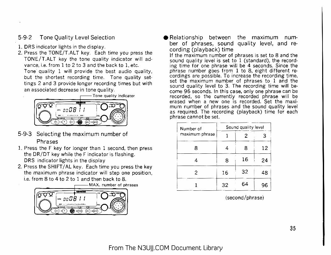
5-9-2 Tone Quality Level Selection
1. DRS indicator lights in the display. 2. Press the TONE/T.ALT key. Each time you press the
TONE/T.AL T key the tone quality indicator will ad· vance, i.e. from 1 to 2 to 3 and the back to 1, etc. Tone quality 1 will provide the best audio quality, but the shortest recording time. Tone quality settings 2 and 3 provide longer recording times but with an associated decrease in tone quality.
Tone quality indicator
5-9-3 Selecting the maximum number of Phrases
1. Press the F key for longer than 1 second, then press the DR/DT key while the F indicator is flashing. DRS indicator lights in the display
2. Press the SHIFT /AL key. Each time you press the key the maximum phrase indicator will step one position, i.e. from 8 to 4 to 2 to 1 and then back to 8.
MAX. number of phrases
rno aaDB I I
e Relationship between the maximum number of phrases, sound quality level, and recording (playback) time If the maximum number of phrases is set to 8 and the sound quality level is set to 1 (standard), the recording time for one phrase will be 4 seconds. Since the phrase number goes from 1 to 8, eight different recordings are possible. To increase the recording time, set the maximum number of phrases to 1 and the sound quality level to 3. The recording time will become 96 seconds. In this case, only one phrase can be recorded, so the currently recorded phrase will be erased when a new one is recorded. Set the maximum number of phrases and the sound quality level as required. The recording (playback) time for each phrase cannot be set.
I Number of Sound quality I~ ; maximum phrase ! 1 2 13 , r- . ' ~ ~- s ___ I 4 ! -~~~~ll ' 4 T;T ~ 24
'
2 16 32 ' 48 J I
1 32 L
64 -~ ' ---- -(second/phrase)
35
From The N3UJJ.COM Document LibraryFrom The N3UJJ.COM Document Library
5·9·4 Recording e Recording an incoming receive signal manually.
1. Select the desired operating frequency. Recordings can be made from the VFO mode, the Memory Mode or the Call Channel mode.
2. Press the F key for longer than a second, then press the DRIDT key while the F indicator is flashing to en· ter the DRS setting mode. The DRS indicator should turn on in the display.
·Select the desired phrase number by rotating the tuning control.
3. Press the VFO I M ..._ V key to begin recording. The recording time indicator will show the elapsed time of the recording.
-Elapsed t1me
·n··g"r-+t1v-· ~ ·-rknB I:
4. Recording will stop when the time indicator reaches "00". To continue recording from the same frequency rotate the tuning control to the next phrase number and then press the VFO I M ..._ V key again to begin recording. Recording will stop when any front panel key is pressed.
36
e Recording Signals from the Microphone 1. Press the F key for longer than 1 second, then press
the DR I DT key while the F indicator is flashing to enter the DRS setting mode. The DRS indicator should turn on in the display. Select the desired phrase number by rotating the tuning control.
2. Press the MR I M key to start recording from the microphone. The recording time indicator will indicate the elapsed time of the recording. If you wish to transmit the same message while recording you should pre,ss the microphone PTT switch before you press the MRIM key.
Elapsed time (U.S.A. ) version .
3. The recording will stop when the elapsed time indicator reaches "00". If you wish to continue recording you will need to rotate the tuning control to the next phrase number and press the MRIM key again. Recording will stop when any front panel key is pressed.
From The N3UJJ.COM Document LibraryFrom The N3UJJ.COM Document Library
5-9-5 Play Back
1. Press the F key for longer than 1 second, then press the DR I DT key while the F indicator is flashing to enter the DRS setting mode. The DRS indicator should turn on in the display. Select the phrase number of the phrase you wish to replay.
2. Press the CALL key to play back the message. If you wish transmit the message at the same time you should press the PTT key before pressing the CALL key. The elapsed time indicator will begin counting the elapsed time.
-, Elapsed time
Q"Q"Q'"• i ns I I : """' CfJu 1 t
3. Playback will stop when the time indicator displays "00". You can manually stop the play back by pressing any front panel key.
5-9-6 Automatic Recording
1. Select the desired operating frequency. Adjust the SQL control to the threshold point. Automatic recording is possible in the VFO mode, Memory Channel mode, or Call Channel mode.
2. Press the F key for longer than 1 second, then press the DR I DT key while the F indicator is flashing to enter the DRS setting mode. Select the desired tone qu(llity, the number of recording phrases, and the beginning phrase number.
3. Press the F key for longer than 1 second, then press the DRIDT key while the F indicator is flashing to en· ter the DTMF control mode. The DRS indicator will flash.
4. Press the TONEIT.AL T key. The T.AL T indicator will light and the recording wait mode (automatic re· cording mode) will be entered.
37
From The N3UJJ.COM Document LibraryFrom The N3UJJ.COM Document Library
5. Only a signal with the proper CTCSS tone (if the TSU-6 is installed ) will initiate recording. If no tone unit is installed the recording will start whenever squelch opens. (The alert function will not sound an alarm.) The CTCSS, DTSS (only reception is possible even if the DTMF unit is not installed), and paging functions are available.
6. If the squelch is closed during recording in the automatic recording mode, recording will finish at the current phrase, and the next phrase will be awaited even if there is recording time remaining. (Recording will not be possible if there is no empty phrase.
OLock canceling
If the third digit of the display is "1", recording is locked, and a new signal cannot be recorded in the same phrase. If the third digit is "2", recording and playback are locked, and a new signal cannot be recorded in the phrase and the phrase cannot be played back. To cancel the lock, press the REV/STEP key so that the third digit become zero(O).
38
5-9-7 External Control of the DRS Function (DTMF control mode)
The DRS function can be remotely controlled by an external DTMF signal.
5-9-8 I D Number Seting
Select a four-digit number from 0000 to 9999. 1. Press the F key for longer than 1 second, then press
the DR/DT key while the F indicator is flashing. The DRS setting mode will be entered and the DRS indicator will light.
Press the key for longer than 1 second.
2. Press the MHz I LOCK key. Four digits will be displayed, and the first digit will flash.
3. Set the first digit with the tuning control, then press the M Hz/LOCK key. The second digit will flash.
From The N3UJJ.COM Document LibraryFrom The N3UJJ.COM Document Library
4. Set the second digit with the tuning control, then press the MHz/LOCK key. The third digit will flash.
5. Set the third and fourth digits. When the fourth digit has been set, the DRS setting mode will be automatically reentered.
The digits can be set with the MC-44DM (option). Perform steps 1 and 2, and key in the number with the numeric keys. Each time a key is pressed, a digit is set. When all the digits have been set, the frequency will be displayed again.
5-9-9 Setting the DTMF Control Mode 1. Select the receive frequency.
2. Enter the DRS setting mode, and specify the number of phrases, sound level, and I D number. (See Sections 5-9-1/2, 5-9-5, and 5-9-8.)
3. While in this state, press the F key for longer than 1 second, then press the DR/DT key while the F indicator is flashing. The frequency will be displayed again and the DRS indicator will flash.
Press the key for longer than 1 second.
4. Press the F key. The DHS indicator will stop flashing and stay on. The transceiver will be ready to be controlled remotely.
The automatic recording mode will be ignored, as will the DTSS and paging modes.
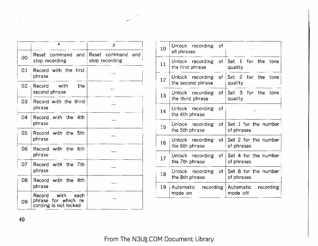
5-9-10 External Control Method For external control, recognition code # or • will transmit a four-digit ID number and three-digit command code.
# 1 2 3 4 *0 1 Leading zeroes in the ID number can be omitted.
eust of DTMF commands See next page
Note: To transmit a DTMF signal, press a key within five seconds of pressing the preceding key. If there is a time delay of longer than five seconds, the DTMF signals that have been tr;ansmitted will be cleared.
39
From The N3UJJ.COM Document LibraryFrom The N3UJJ.COM Document Library
02 , Record with the ' - I second phrase ' ···-- ----------------- .... -____
03 Record with the third -phrase
04 Record with the 4th I
phrase -
05 Record with the 5th phrase
06 Record with the 6th i -:phrase
I 07 Record with the 7th -phrase i
08 Record ·with the 8th -
phrase
I ----
1 Record with each -
09 J phrase for which re-cording is not locked
40
r 10 I Unlock recording of I'
· all phrases
~-~ Unlock ~r~e~c~or~d~ing of i Set 1 for
! the first phrase • quality
12 Unlock recording of • Set 2 for
1 the second phrase J quality
the tone i
···~ the tone 1
the 13
1 Unlock recording of I Set. 3 -for
I the third phrase 1
qualit_Y _____ _,
14 1 Unlock recording of ·
tone I
I J the 4th phrase [
'Unlook "'o'ding of I Set 1 fo' the ""mb" 15 the 5th phrase of phrases
r.' 16 I. Unlock recording of ! s._e_t_2_f_o_r_t_h_e_n_u_m_b_e--jr
~--~--+I t_h_e 6th phrase : of phrases
17 • Unlock recording of Set 4 for the number i the 7th phrase of phrases
118
, Unlock recording of Set 8 for the number
~ ' the 8th phrase of phrases
I 19 I Automatic recording Automatic recording ~de on mode off
From The N3UJJ.COM Document LibraryFrom The N3UJJ.COM Document Library
5-10 PAGING The paging function is available when the optional DTMIF unit (DTU-2) is installed. The paging function is useful to call all stasions a group, a sp13cific station, or wait for a call from another station by using DTMF(Duai Tone Multi Frequency signaling.
Example: When station 2 is called
F: 145.66DMHz
~~~MHz 333 Ill
, L<:.L_--l=..=:...L... __ ..L...u...L. Sta liOn 2's
,} code
~~~ F: 145.660MHz
lnd1v1dual code : 222 Stat1un I
F: 145.66DMHz lnd1v1dual code : 333
Stat1on 2
Your code
'\l ~?
F: 145.660MHz lnd1v1dual code : 444
Stat1on 3
The common group code and individual codes should be determined in advance. These codes should be from 000 to 999 (3 digits). Unlike DTSS, the code of the calling station is displayed on the receiver, so the receiver can identify the calling station. When called by a local station, the individual code of the calling station is displayed. When called with a group code, that group code is displayed.
Paging operation procedure
Set your station code
Tune to frequency of the other station I
I Enter the paging mode J
• To call the other To stand by for a station pager
Set the code of station to be called
Transmit
Call Stand by
41
From The N3UJJ.COM Document LibraryFrom The N3UJJ.COM Document Library
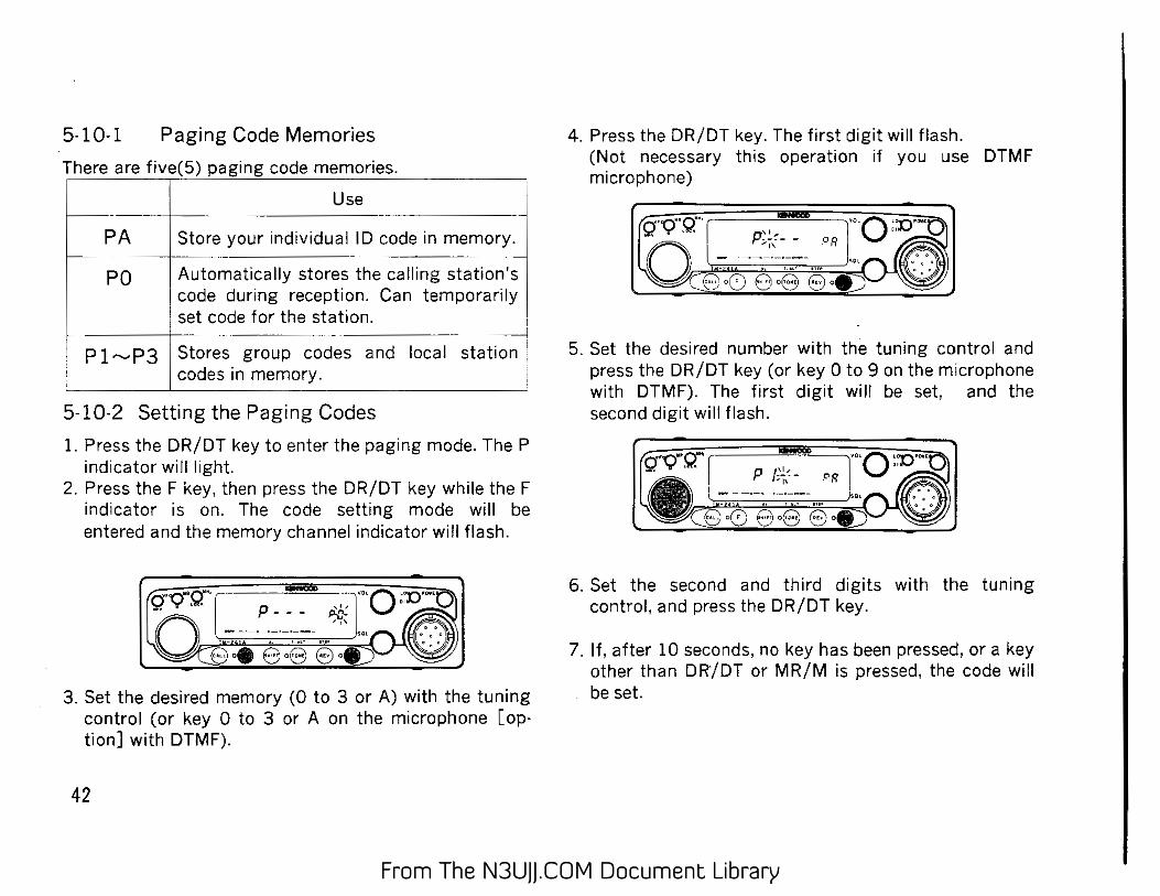
5-10-1 Paging Code Memories
There are five(5) paging code memories. ;·····
.... ·-·-~
' Use
PA 1 Sto~= your individual ID code in memory ..
PO Automatically stores the calling station's ' code during reception. Can temporarily set code for the station.
P1"'-'P3 I Stores group codes and local station . codes m memory.
5-10-2 Setting the Paging Codes
1. Press the DR/DT key to enter the paging mode. The P indicator will light.
2. Press the F key, then press the DR/DT key while the F indicator is on. The code setting mode will be entered and the memory channel indicator will flash.
p- - -·-.,.,.o " ......... ~.
· tr<A..tl
~:I' ' . ' ""
3. Set the desired memory (0 to 3 or A) with the tuning control (or key 0 to 3 or A on the microphone [option] with DTMF).
42
4. Press the DR/DT key. The first digit will flash. (Not necessary this operation if you use DTMF microphone)
5. Set the desired number with the tuning control and press the DR/DT key (or key 0 to 9 on the microphone with DTMF). The first digit will be set, and the second digit will flash.
6. Set the second and third digits with the tuning control, and press the DR/DT key.
7. If, after 10 seconds, no key has been pressed, or a key other than DR/DT or MR/M is pressed, the code will be set.
From The N3UJJ.COM Document LibraryFrom The N3UJJ.COM Document Library
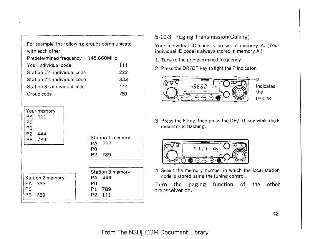
For example, the following groups communicate
with each other.
Predetermined frequency 145.660MHz
Your individual code 111
Station l's individual code 222
Station 2's individual code 333
Station 3's individual code
Group code
Your memory PA 111 PO Pl
• P2 444 P3 789
ation 2 memory I
.P~ 333 _j! :; P3 789 L:: .
444
789
1 Station 1 memory PA 222 PO P2 789
Station 3 memory PA 444 PO Pl 789
I P2 111
5-10-3 Paging Transmission(Calling)
Your individual ID code is preset in memory A. (Your individuaiiD code is always stored in memory A.)
1. Tune to the predetermined frequency.
2. Press the DR/DT key to light the P indicator.
~~==~~~~~-p indicates the paging
3. Press the F key, then press the DR/DT key while the F indicator is flashing.
4. Select the memory number in which the local station code is stored using the tuning control.
Turn the paging function of the other transceiver on.
43
From The N3UJJ.COM Document LibraryFrom The N3UJJ.COM Document Library
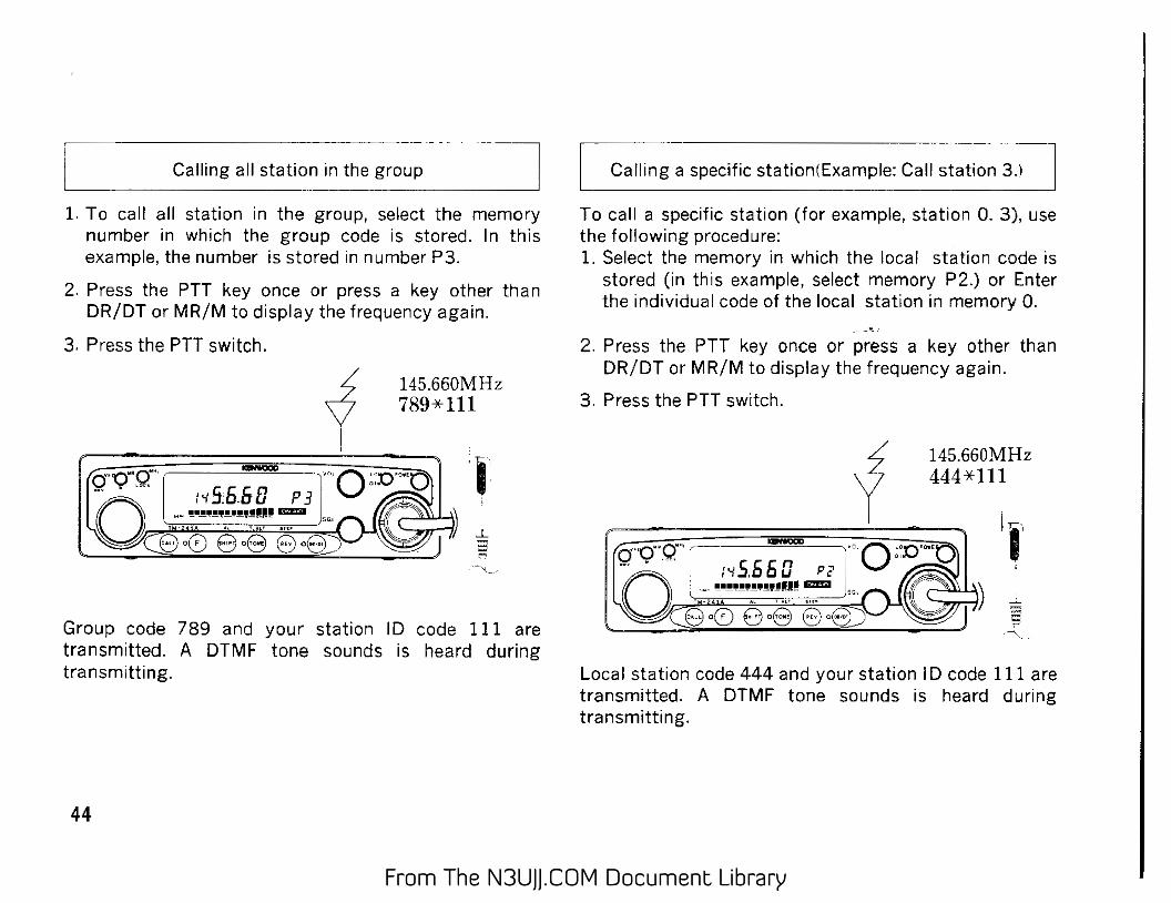
Calling all station in the group
1. To call all station in the group, select the memory number in which the group code is stored. In this example. the number is stored in number P3.
2. Press the PTT key once or press a key other than DR/DT or MR/M to display the frequency again.
3. Press the PTT switch.
145.660MHz 789* 111
Group code 789 and your station ID code 111 are transmitted. A DTMF tone sounds is heard during transmitting.
44
--·········-·---------
Calling a specific station(Example: Call station 3.)
To call a specific station (for example, station 0. 3), use the following procedure: 1. Select the memory in which the local station code is
stored (in this example, select memory P2.) or Enter the individual code of the local station in memory 0.
2. Press the PTT key once or press a key other than DR/DT or MR/M to display the frequency again.
3. Press the PTT switch.
1 I
145.660MHz 444*111
Local station code 444 and your station I D code Ill are transmitted. A DTMF tone sounds is heard during transmitting.
From The N3UJJ.COM Document LibraryFrom The N3UJJ.COM Document Library
5-10-4 Paging Reception (Stand by)
1. Tune to the predetermined frequency. 2. Press the DR/DT key to light the P indicator.
i Stand by with individual code (Example: Stand by for station 3.)
3 When called with your station ID code, the memory number automatically change to 0. The ID code of the member 3 is displayed.
local statio,n code
,.---1~ .. ~
p' '-/ '-1 '-1
~-is displayed to indicate thatl t!our station is being called. __j
4. The squelch is opened.
5. The individual code of the calling station is stored in memory 0. Press the PTT switch to respond to the calling station.
145.660MHz 444*111
When the transmission ends, the frequency will be dis· played again. After the local station has been contacted, cancel paging mode. Communication can be performed more efficiently.
If the local station code can not be decorded, "Err" appears on the display.
Err PG S&AI' -1-3-5-?-S-OVEA-
45
From The N3UJJ.COM Document LibraryFrom The N3UJJ.COM Document Library
Stand by with group
L When a call is received with the group code, the squelches of all the members of the group are opened to enable reception.
When you are called with the group code, the common group code and its memory channel number are displayed. (Example: Group code 789 is stored in channel 3.)
Group code Flashing
SSRF -1···--3-.,_,-- i~---··>-1-[JVfR-
13 is displayed t~ indicatethat the I . station is being called. ·-..... ---------------
2. When the PTT switch is pressed, group code 789 (as displayed) and your station ID code are transmitted. You< can participate in the group-roundtable.
3. After the remote station has been called, cancel paging mode. Communication can be performed more efficiently.
46
5-l 0-5 Code Lockout (A code is locked out only during reception with thE~
paging function.)
If an individual code is stored in P l,P2 or P3, reception is 'enabled when the codes match, even if one local station communicates with another. To use memories Pl to P3 for transmission only, lock out the memories. When you are communicating with two or more groups having the same frequency, lock out the group code with which stand by is temporarily stopped.
,. Paging memory lockout
1. Enter the code setting mode and display the number (except memory 0 and A) to be locked out using the tuning control.
2. Press the MR/M key . *mark lights and the memory is locked out.
3. To cancel, repeat steps 1 and 2.
From The N3UJJ.COM Document LibraryFrom The N3UJJ.COM Document Library
5-11 TONE ALERT SYSTEM
The Tone Alert function will provide an audible "Alarm" to signal when someone is transmitting on the frequenc~you are monitoring:_ ___ ·---·· ~
Note 1 When using the CTCSS function the incoming sig
nal must be present for approximately 2 seconds in order for the Tone Alert function properly.
2. When the DTSS function is on, the bell function works only when the DTSS code matches. .
3 When the paging function is on, the bell functton works on; when the code matches.
1. Adjust the SQL control to the threshold point. 2. If you will be using the CTCSS functiOn you should
select the proper tone frequency and ensure the cress indicator is on. If you will be using the DTSS function you should select the proper DTSS codes and ensure the DTSS indicator is on. If you will be using the PAGING function you should select the proper PAGING codes ana ensure the P indicator is on.
3. Press the F key and then the TONE/T.AL T key. The T.AL T indicator will light.
4. When a signal is received and the squelch is open, an alarm sounds for about five seconds, the T.AL T indicator flashes, and the elapsed time count begins.
5. The elapsed time is displayed in minutes to up to 59 hours 59 minutes. If a new signal is received during counting, the elapsed time is cleared, and the elapsed time from the new signal being received IS
counted. Flashing
_jx 551.59 / 1
- .. -·-·-· . ·"""'-
6. If a key is pressed wh1le the elapsed time is being displayed, the T.AL T function is released.
7. To release the T.AL T function when no signal is being received, press the TONE/T.AL T key again _ .
fl\fo-tes l · 1 When the PF key on the microphone is set as the
1
monitor key, the voice can be monitored by press- · ing the PF key while the T.AL T function is working: 1
2. The T.AL T function may fail if the received s1gnalts 1! abandoned (audio low-frequency distort1on, 1gn1-tion noise, etc.). In this case, the Interference can . be reduced by installing an optional TSU-6 and setting the CTCSS frequency to 141.3 Hz or lower. When a repeater is used, the CTCSS function is not available. It is recommended to use it with the DTSS function.
3. The tone Alert System can not be use in conjunction with Scan.
47
From The N3UJJ.COM Document LibraryFrom The N3UJJ.COM Document Library
5-12 APO (Automatic Power Off) · The automatic power-off function turns the power off
automatically if you forget. It does not operate during scanning. The initial setting IS OFF.
1. To turn the APO function off and on, press the F key for longer than 1 second, then press the MHz/LOCK key within 10 seconds. The APO indicator lights.
2. If, after 2 hours 59 minutes in inactive receive mode, no key has been pressed, the APO indicator flashes and a beep sounds. If no key is pressed for 1 minute after that, the display indicates the following, all the functions are disabled, and the transceiver enters the automatic power-off state.
3. To leave the automatic power-off state, turn the power switch off and on again.
r , JNO~S I 1 1. A small current flows during the automatic power off state. If · the transceiver is not going to be used, be sure to switch the 1
, power oil. . _ . _ 1
I 2. If the APO functton ts turned on and then the bell funct1on IS ;
1 turned on, the automatic power-off function does not work un- I
I til the bell function is turned off (though the indicator lights). I
3. This function is not available when the remote controller is con· I L nected. _ _ _ ---~~----~~-~-j
48
5-13 DIM (DIMMER) The intensity of dial illumination can be set to one of four levels.
1. Press the F key, then press the LOW/DIM key while the F indicator lights.
a·,rg· L-~-~----.7:J:::o :l&-·
GoeeQe 8o8 ~
2. Select the desired value with the tuning control or the UP /OWN key on the microphone.
3. If, after 10 seconds, no key has been pressed, the dis· played level is set and the original frequency is redisplayed.
From The N3UJJ.COM Document LibraryFrom The N3UJJ.COM Document Library
5-14 BEEP
The beep can be turned on and off.
Press the F key for longer than 1 second, then press the REV /STEP key while the F indicator is flashing. Each time this is done, the beep is turned on or off.
<;j'~··Q-·~5 5 ~ n !'"{ • uu - - -· ··-·-·--·-
' .- " ,.,. ""
Press the key for longer than 1 second.
5-15 LOCK I A.LOCK
There are three types of lock functions.
CD Microphone key lock When the switch on the rear of the microphone is set to the LOCK position, all the microphone keys except the PTT key are disabled.
~LOCK The panel keys (except F and MHz/LOCK key) and the tuning control are disabled. However, the microphone function works. Press the F key, then press the MHz/LOCK key within 10 seconds. The LOCK indicator lights.
To release the lock, press the F key again, then press the MHz/LOCK key within 10 seconds.
@ A.LOCK(ALL LOCK) All operations, except the power switch, volume, and squelch, are disabled.
Switch the power off while the LOCK indicator is on, hold down the MHz/LOCK key, and switch the power on again. The A.LOCK indicator lights.
To release A.LOCK, switch the power off while the A.LOCK indicator is on, hold down the MHz/LOCK key, then switch the power on again. The A.LOCK operation
I • cannot be canceled by VFO or MR reset.
49
From The N3UJJ.COM Document LibraryFrom The N3UJJ.COM Document Library
7 MAINTENANCE 7-1 GENERAL INFORMATION
Your transceiver has been factory aligned and tested to specification before shipment. Under normal circumstances the transceiver will operate in accordance with these operating instructions. All adjustable trimmers and coils in your transceiver have been adj.;sted at the factory and should only be readjusted by a qualified technician with proper test equipment. Attempting service or alignment without factory authorization can void the transceiver's warranty. When operated properly, the transceiver will provide many years of service without requiring realignment. The in· formation in this section gives some general service procedures which can be accomplished without sophisticated test equipment. · ·· 7-2 SERVICE If it ever become necessary to return the equipment to your dealer or service center for repair, pack it in its original box and packing, and include a full description of the problems involved. Please include your daytime telephone number. You need not return accessory items unless directly related to the service problem. Service note: Dear OM, if you desire to correspond on a technical or operational problem, please make your note short, complete, and to the point, and PLEASE make it readable.
Please list: Model and serial number. The problem you are having.
Please give sufficient detail for diagnosis. Provide information such as other equipment in the station, meter readings and anything else you feel might be useful in attempting diagnosis. Caution: Do not pack the equipment in crushed newspapers for shipment. Extensive damage may result during shipment. Notes: 1. Record the date of purchase, serial number and dealer from whom purchased. 2. For your own information, retain a written record of any maintenance performed on the unit. 3. When claiming warranty service, please include a photocopy of the bill of sale, or other proof of purchase
showing the date of sale.
50
,
From The N3UJJ.COM Document LibraryFrom The N3UJJ.COM Document Library
7-3 IN CASE OF DIFFICULTY The problems described in this table are failures caused, in general, by improper operation or connection of the transceiver, not by defective components. Check according to the following table.
Symptom I Probable cause i
Correct've act1on
Indicators do not light and no receiver noise is 1
1. Bad power cable or connections. 11.
Check cables and connections. heard when the POWER switch is turned on. ; 2. Blown power supply fuse. 2 Check for the cause of the blown fuse
and replace the fuse. r----· .. ·-·--·-·---·- -~·-·-·-·-·-·-·---·-·
No sound from the speaker. No signal can be 1
L SqueJc:, is closed. .1. Turn the S%L control counterclockwise. received. i 2. With the TSU·6: CTCSS is operating. i2 Press the T NE/T.ALT key to turn offthe
CTCSS. 1-- ..
! 1 !1. -------~----
No transmitter output. I . Microphone is not plugged in. Plug jack in .. . 2. Poor antenna connection. I vu""~' antenna securely.
Weak signal cannot be received. I P, a""""' 1a connection. 1 (.;<.,'""'"''antenna securely.
Display is dark .1. Power voltage is low. !1. Check voltage for 13.8 VDC ± 15 %. 12. The DIM had been selected too dark. . 2. Press the F key and the LOW /DIM key.
I Seepage48
Memory cannot be backed up. 1
Back up battery voltage is low. See Microprocessor memory backup page 21.
The display will not change when the tuning : 1. The Jock IS on. 11. Press the MHz/LOCK key within ten
control is rotated or a key is pressed. i 2. A. LOCK is on. ! seconds of pressing the F key.
2. Hold down the MHz/LOCK key, switch i the power on, then perform the opera·
' I
tion in 1.
51
,
From The N3UJJ.COM Document LibraryFrom The N3UJJ.COM Document Library
8. OPTIONAL ACCESSORIES
• MC-44/MC-44E (E: European Version) MUL Tl FUNCTION MICROPHONE
• MC-60A MICROPHONE (8-pin) The zinc d1e-cast base provides high stabilityThe MC-60A IS complete with PTT and LOCK sw1tches, UP/DOWN switches, impedance selector swttch and a built-in preamplifier_
Using MC-60A with the transceiver does not comply with the European EMC standard.
• SP-41 MOBILE SPEAKER (4 ohms)
• MC-44DM/MC-44DME (E: European Vers1on) MUL Tl FUNCTION MICROPHONE WITH AUTOPATCH
• MC-80 MICROPHONE (8-pin) The MC-80 is an omnidirectional electret condenser microphone that Is orovided with UP/DOWN switches, volume adjustment for output level, PTT anc LOCK switches, and a bu1l\-1n pre-amplifier_ /-• SP·50B MOBILE SPEAKER (8 ohms) Compact and smart, htgh quality external speaker provides flexibility or installation for maximum conventence.
• MC-85 MICROPHONE (8-pin) The MC-85 IS a unidirectional h1gh-class electret condenser microphone provided with an output selector sw1tch, audio level compensation circuit, iow cut filter, level meter, PTT ana LOCK switches.
• PS-33 REGULA TED DC POWER SUPPLY
• DTU-2 DTMF UNIT
NOTE: 1750 Hz repeater access tone is only available from MC·44E or MC-44DME European version microphone_
52
I
From The N3UJJ.COM Document LibraryFrom The N3UJJ.COM Document Library
• TSU-6 CTCSS UNIT
• PG-3G DC LINE NOISE FILTER
• DRU-1 • PG-2N DIGITAL RECORDING DC POWER CABLE UNIT
• MB-201 • MB-12 MOBILE MOUNTING BRACKET MOBILE MOUNTING
BRACKET
53
From The N3UJJ.COM Document LibraryFrom The N3UJJ.COM Document Library
Installing a~cessories . CAUTION 1. Before installation , be sure to disconnect the DC
power supply,or battery, or damage may occur the equipment.
2. You can not install the digital recording unit(DRU 1) and the DTMF unit together. You should choose one unit to install.
CTCSS unit TSU-6 The use of the optional sub-audible tone decoder TSU· 6 allows CTCSS (Tone squelch} operation. When this op· tion is active squelch Will onfy open when the proper tone is received.
Installation 1. Remove the 2 screws secur
ing the Top cover. 2. CarefullY. remove the top
cover .. (Fig.l) 3. Remove the backing from
the small cushion provided with the TSU-6 and attach it to the back of the TSU-6 as shown in Fig. 2.
4. Attach the cable from TSU-6 as shown in Fig. 2. Cushion •..
5. Remove the backing from the other side of the small cushion and attach the TSU-6 to the transceiver as shown.
6. Replace the cover and tighten the screws to complete the installa· tion.
54
Fig. 1
TSU-5 unrt
Fig. 2
Digital Recording Unit DRU-1 1. Remove the 2 screws se
curing the Top cover. Carefully remove the top cover. (Fig. 1)
2. Attach the three cables from the DRU-1 in the Fig.3 transceiver as shown in Fig. 3. Don't forget to at· tach the TSU-6 as shown if you are installing this un1t at the same time (Fig. 4).
3. Tighten the screws (Fig. 5).
4. Replace the cover and tighten the screws to complete the installa· tion.
\
\ " Rou7e the W!rll"'Q
Fig. 4
Fig. 5
From The N3UJJ.COM Document LibraryFrom The N3UJJ.COM Document Library
DTMF unit DTU-2 1. Remove the 2 screws securing the Top cover.
2. Carefully remove the top cover. (Fig.l )
3. Remove the backing from the small cushion provided with the DTU-2 and attach it to the back of the DTU-2 as shown in Fig. 2
4. Plug the three connectors into the sockets in the units.
5. Attach the cable from DTU-2 as shown in Fig. 2 and 3.
6. Replace the cover and tighten the screws to complete the installation.
Olnstalling TSU-6 and DTU-2
Attach these units on the top of VCO shield (Fig.3).
DTU-2
Fig. 1
Fig. 2
l'ig. 3
55
From The N3UJJ.COM Document LibraryFrom The N3UJJ.COM Document Library
56
From The N3UJJ.COM Document LibraryFrom The N3UJJ.COM Document Library