TM 5-4320-275-13 & P This copy is a reprint which includes current pages from Changes 1 through 5. TECHNICAL MANUAL OPERATOR'S, ORGANIZATIONAL, AND DIRECT SUPPORT MAINTENANCE MANUAL, INCLUDING REPAIR PARTS AND SPECIAL TOOLS LIST FOR PUMP, RECIPROCATING, POWER-DRIVEN, DIAPHRAGM, GASOLINE-ENGINE-DRIVEN, WHEEL-MOUNTED PEABODY BARNES MODEL US40CDG 4320-01-092-2210 INTRODUCTION 1-1 OPERATING INSTRUCTIONS 2-1 OPERATOR/CREW MAINTENANCE INSTRUCTIONS 3-1 ORGANIZATIONAL MAINTENANCE INSTRUCTIONS 4-1 DIRECT SUPPORT MAINTENANCE INSTRUCTIONS 5-1 REFERENCES A-1 MAINTENANCE ALLOCATION CHART B-1 REPAIR PARTS AND SPECIAL TOOLS LIST C-1 EXPENDABLE SUPPLIES AND MATERIALS LIST D-1 GLOSSARY ALPHABETICAL INDEX HEADQUARTERS, DEPARTMENT OF THE ARMY 1 MARCH 1983
Transcript
TM 5-4320-275-13 & PThis copy is a reprint which includes currentpages from Changes 1 through 5.
TECHNICAL MANUAL
OPERATOR'S, ORGANIZATIONAL, ANDDIRECT SUPPORT MAINTENANCE MANUAL,
INCLUDING REPAIR PARTSAND SPECIAL TOOLS LIST
FOR
PUMP, RECIPROCATING, POWER-DRIVEN,
DIAPHRAGM, GASOLINE-ENGINE-DRIVEN,WHEEL-MOUNTED
PEABODY BARNES MODELUS40CDG
4320-01-092-2210
INTRODUCTION 1-1
OPERATING INSTRUCTIONS 2-1
OPERATOR/CREWMAINTENANCE INSTRUCTIONS 3-1
ORGANIZATIONALMAINTENANCE INSTRUCTIONS 4-1
DIRECT SUPPORTMAINTENANCE INSTRUCTIONS 5-1
REFERENCES A-1
MAINTENANCEALLOCATION CHART B-1
REPAIR PARTS ANDSPECIAL TOOLS LIST C-1
EXPENDABLE SUPPLIESAND MATERIALS LIST D-1
GLOSSARY
ALPHABETICAL INDEX
HEADQUARTERS, DEPARTMENT OF THE ARMY
1 MARCH 1983
TM 5-4320-275-13&PC5
CHANGE HEADQUARTERSDEPARTMENT OF THE ARMY
NO. 5 WASHINGTON, D. C. 15 October 1993
Operator's, Organizational, and Direct Support Maintenance ManualIncluding Repair Parts and Special Tools List
DISTRIBUTION STATEMENT A: Approved for public release; distribution is unlimited.
TM 5-4320-275-13&P, 1 March 1983, is changed as follows:
1. Remove and insert pages as indicated below. New or changed text material is indicated by a vertical bar in themargin. An illustration change is indicated by a miniature pointing hand.
Remove pages Insert pages
i and ii i and ii1-1 and 1-2 1-1 and 1-2C-17 and C-18 C-17 and C-18C-25 and C-26 C-25 and C-26
2. Retain this sheet in front of manual for reference purposes.
By Order of the Secretary of the Army:
GORDON R. SULLIVANGeneral, United States Army
Official: Chief of Staff
MILTON H. HAMILTONAdministrative Assistant to the
Secretary of the Army05529
DISTRIBUTION:To be distributed in accordance with DA Form 12-25-E, block no. 1426, requirements for TM 5-4320-275-13&P.
TM 5-4320-275-13&PC4
CHANGE HEADQUARTERSDEPARTMENT OF THE ARMY
NO. 4 WASHINGTON, D. C. , 25 January 1991
Operator's, Organizational, and Direct Support Maintenance ManualIncluding Repair Parts and Special Tools List
Approved for public release; distribution is unlimited
TM 5-4320-275-13&P, 1 March 1983, is changed as follows:
1. Remove and insert pages as indicated below. New or changed text material is indicated by a vertical bar in themargin. An illustration change is indicated by a miniature pointing hand.
Remove pages Insert pages
C-11 through C-14 C-11 through C-14C-25 and C-26 C-25 and C-26
2. Retain this sheet in front of manual for reference purposes.
By Order of the Secretary of the Army:
CARL E. VUONOGeneral, United States Army
Chief of Staff
Official:THOMAS F. SIKORA
Brigadier General, United States ArmyThe Adjutant General
DISTRIBUTION:To be distributed in accordance with DA Form 12-25E, (qty rqr block no. 1426)
TM 5-4320-275-13&PC3
CHANGE HEADQUARTERSDEPARTMENT OF THE ARMY
No. 3 WASHINGTON, D. C. , 4 April 1988
Operator's, Organizational, andDirect Support Maintenance Manual
TM 5-4320-275-13 & P, 1 March 1983, is changed as follows:1. Remove and insert pages as indicated below. New or changed text material is indicated by a vertical bar in
the margin. An illustration change is indicated by a miniature pointing hand.
Remove pages Insert pages
i and ii i and ii1-1 and 1-2 1-1 and 1-2
4-83 and 4-84 4-83 and 4-84A-1/A-2 A-1/A-2
B-1 through B-6 B-1 through B-62. Retain this sheet in front of manual for reference purposes.
By Order of the Secretary of the Army:
CARL E. VUONOGeneral, United States Army
Chief of Staff
Official:
R. L. DILWORTHBrigadier General, United States Army
The Adjutant General
DISTRIBUTION:To be distributed in accordance with DA Form 12-25A, Operator's, Unit, and Direct Support and General Support
Maintenance requirements for Pump, Reciprocating, Diaphragm, Gas Driven, Power Driven, Wheel Mounted(US40CDG) (TM 5-4320-275-13&P)
TM 5-4320-275-13&PC2
CHANGE HEADQUARTERSDEPARTMENT OF THE ARMY
NO 2 WASHINGTON, D. C. , 30 November 1987
Operator's Organizational, andDirect Support Maintenance Manual,
TM 5-4320-275-13&P, 1 March 1983, is changed as follows:1. Remove and insert pages as indicated below. New or changed text material is indicated by vertical bar in
the margin. An illustration change is indicated by a miniature pointing hand.
Remove pages Insert pages
C-17 and C-18 C-17 and C-18C-25 and C-26 C-25 and C-26
2. Retain this sheet in front of manual for reference purposes.
By Order of the Secretary of the Army:
CARL E. VUONOGeneral, United States Army
Chief of Staff
Official:
R. L. DILWORTHBrigadier General, United States Army
The Adjutant General
DISTRIBUTION:To be distributed in accordance with DA Form 12-25A, Operator, Unit, and Direct Support and General Support
Maintenance Requirements for Pump, Reciprocating, Diaphragm, Gas Driven, Power Driven, Wheel Mounted(US40CDG).
TM 5-4320-275-13&PC1
CHANGE HEADQUARTERSDEPARTMENT OF THE ARMY
No. 1 WASHINGTON, D. C. , 2 September 1986
Operator's, Organizational, andDirect Support Maintenance Manual,
TM 5-4320-275-13 & P, 1 March 1983, is changed as follows:
1. Remove and insert pages as indicated below. New or changed text material is indicated by a vertical bar inthe margin. An illustration change is indicated by a miniature pointing hand.
Remove pages Insert pages
C-7 and C-8 C-7 and C-8C-13 through C-16 C-13 through C-16C-21 through C-26 C-21 through C-26
2. Retain this sheet in front of manual for reference purposes.
By Order of the Secretary of the Army:
JOHN A. WICKHAM, JR.General, United States Army
Official: Chief of Staff
R. L. DILWORTHBrigadier General, United States Army
The Adjutant General
DISTRIBUTION:to be distributed in accordance with DA Form 12-31, Operator's, Organizational, Direct Support and General
Support Maintenance requirements for Pump, Reciprocating, Diaphragm, Gas Driven, Power Driven, Wheel Mounted(US40CDG) (TM 5-4320-275-13&P)
TM 5-4320-275-13&PWARNING
CARBON MONOXIDEis produced by the internal combustion engine of this pump.
DEATHmay result if personnel fail to observe safety precautions.
Carbon monoxide is a colorless, odorless, deadly poisonous gas which, when breathed, deprives the bodyof oxygen and causes suffocation. Exposure to air contaminated with carbon monoxide producessymptoms of headache, dizziness, loss of muscle control, or apparent drowsiness. Coma, permanentbrain damage, or death can result from severe exposure.
Carbon monoxide occurs in the, exhaust fumes of internal combustion engines and becomes dangerouslyconcentrated under conditions of inadequate ventilation. Observe the following safety precautionswhenever the engine is running:
• Perform tests outdoors or in a well-ventilated area.• Do not idle the engine for long periods without maintaining adequate ventilation.• Be alert at all times for exhaust odors and exposure symptoms.• Be aware: the field protective mask for chemical-biological-radiological (CBR) protection willnot protect you from carbon monoxide poisoning.
Expose victims to fresh air, keep warm, and do not permit physical exercise. For artificial respiration, referto FM21-11.
SEVERE BURNS
illness, death, or injury may result if personnel fail to handle gasoline properly. Observe the followingsafety precautions:
• Do not inhale vapor.• Do not refuel a hot or running engine.• Do not refuel near open flame, sparks, or excessive heat.• Be certain fuel lines and connections are secure.• Do not overfill the fuel tank.• Work in a well-ventilated area.
Allow an engine and pump to cool before performing any service or maintenance.
a
TM 5-4320-275-13&PWARNING
PERSONAL INJURYmay result if the engine cutoff switch is not turned off for service or maintenance.
ELECTRICAL SHOCKmay result from performing maintenance while the engine is running. The ignition system of this enginecontains dangerous voltages which can cause severe electrical shock.
HEALTH AND SAFETY HAZARDexists when cleaning solvents are used. Clean all parts in a well-ventilated area. Avoid inhalation ofsolvent fumes and prolonged exposure of skin to cleaning solvent. Wash exposed skin thoroughly. Drycleaning solvent (fed. spec. P-D-680) used to clean parts is potentially dangerous to personnel andproperty. Do not use near open flame or excessive heat. Flash point of solvent is 100° to 138°F (38° to59°C).
EYE INJURYmay result when parts are cleaned with compressed air. Use approved safety glasses, goggles, or faceshield to prevent eye injury.
EXPLOSION HAZARDexists when welding repairs are attempted on fuel tank.
b
TM 5-4320-275-13 & P
TECHNICAL MANUAL HEADQUARTERSTM 5-4320-275-13 & P DEPARTMENT OF THE ARMY
WASHINGTON, D. C. , 1 March 1983
OPERATOR'S, ORGANIZATIONAL, ANDDIRECT SUPPORT MAINTENANCE MANUAL,
You can help improve this manual. If you find any mistake or if you know of a way to improve theprocedures, please let us know. Mail your letter, DA Form 2028 (Recommended Changes to Publicationsand Blank Forms). or DA Form 2028-2 located in the back of this manual directly to: Commander, U. S.Army Aviation and Troop Command, ATTN: AMSAT-I-MP, 4300 Goodfellow Blvd. , St. Louis, MO 63120.A reply will be furnished to you.
DISTRIBUTION STATEMENT A: Approved for public release; distribution is unlimited
IllusPage Figure
CHAPTER 1. INTRODUCTION ............................................................................ 1-1Section I. General Information ........................................................................ 1-1Section II. Equipment Description and Data .................................................... 1-2Section III. Principles of Operation ................................................................... 1-5
CHAPTER 2. OPERATING INSTRUCTIONS ............................................................. 2-1Section I. Description and Use of Operator's Controls and Indicators .............. 2-1Section II. Operator/Crew Preventive Maintenance Checks and Services ........ 2-2Section III. Operation Under Usual Conditions .................................................. 2-5Section IV. Operation Under Unusual Conditions .............................................. 2-10
CHAPTER 3. OPERATOR/CREW MAINTENANCE INSTRUCTIONS ........................ 3-1Section I. Lubrication Instructions ................................................................... 3-1Section II. Troubleshooting Procedures ........................................................... 3-1Section III. Maintenance Procedures ................................................................ 3-4
Section I. Repair Parts, Special Tools, TMDE, and Support Equipment .......... 4-1Section II. Service Upon Receipt...................................................................... 4-2 4-1Section III. Operational Checks ........................................................................ 4-5Section IV. Preventive Maintenance Checks and Services ............................... 4-7Section V. Troubleshooting ............................................................................ 4-14Section VI. Maintenance Procedures ................................................................ 4-23Section VII. Preparation for Storage or Shipment ............................................... 4-84
Change 5 i
TM 5-4320-275-13 & P
IllusPage Figure
CHAPTER 5. DIRECT SUPPORT MAINTENANCE INSTRUCTIONS ........................ 5-1Chapter Overview .................................................................... 5-1
Section I. Repair Parts, Special Tools, TMDE, and Support Equipment ... 5-1Section II. Troubleshooting ....................................................................... 5-2Section III. Maintenance Procedures .......................................................... 5-3
APPENDIX A. REFERENCES ..................................................................................... A-1
APPENDIX B. MAINTENANCE ALLOCATION CHART ............................................... B-1
Section I. Introduction .................................................................................... B-1Section II. Maintenance Allocation Chart ......................................................... B-4Section III. Tool and Test Equipment Requirements ......................................... B-5Section IV. Remarks ......................................................................................... B-5
APPENDIX C. ORGANIZATIONAL AND DIRECT SUPPORT MAINTENANCEREPAIR PARTS AND SPECIAL TOOLS LIST ...................................... C-1
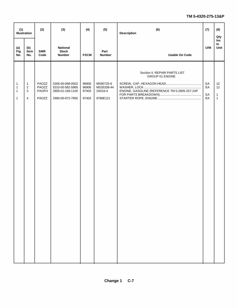
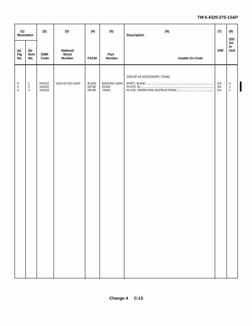
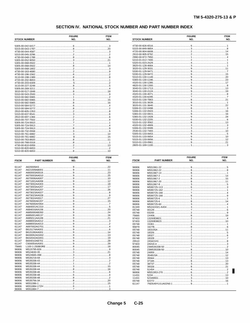
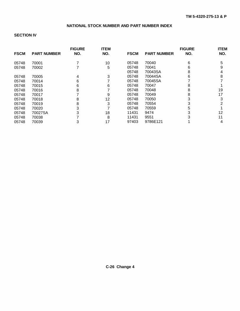
Section I. Introduction ..................................................................................... C-1Section II. Repair Parts List ............................................................................. C-7
Group 01 EngineEngine Assembly ................................................ C-7 1
Group 02 Fuel SystemTank, Line, Fittings and Filter ............................. C-9 2
Group 03 FrameFrame Assembly and Wheels ............................. C-11 3
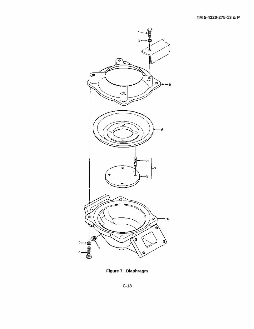
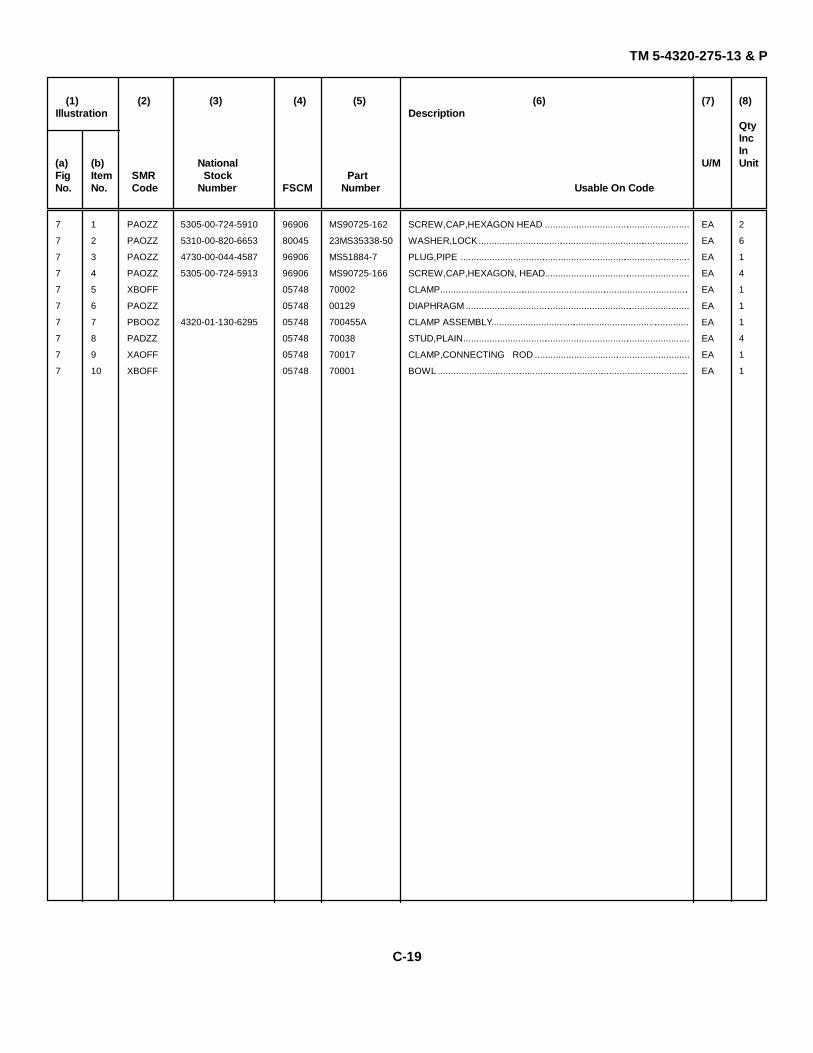
Group 05 PumpAccumulator, Check Valve Assemblies andDischarge Port .................................................... C-17 6Diaphragm ......................................................... C-19 7Connecting Rod Assembly .................................. C-21 8Gear Reducer ..................................................... C-23 9
Section III. Special Tools List (Not Applicable) .................................................Section IV. National Stock Number and Part Number Index ............................. C-25
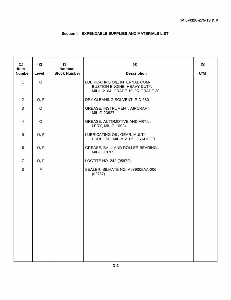
APPENDIX D. EXPENDABLE SUPPLIES AND MATERIALS LIST .............................. D-1
ALPHABETICAL INDEX ................................................................................................. Index 1
ii Change 3
TM 5-4320-275-13 & P
HOW TO USE THIS MANUAL
This manual consists of:
1. Introduction to Model US40CDG Diaphragm Pump.
2. Principles of operation describing the functions of the diaphragm pump.
3. Maintenance instructions for operator, organizational, and direct support maintenance. These chapters contain:
a. Information on repair parts, special tools, 'test, measurement and diagnostic equipment (TMDE), and
support equipment
b. Instructions for service upon receipt of the diaphragm pump
c. Operational checks
d. Preventive maintenance checks and services (PMCS)
e. Troubleshooting
f. Maintenance procedures
4. Appendixes in the back of the manual list:
a. References
b. Maintenance Allocation Chart
c. Repair parts and special tools
d. Expendable supplies and materials
You will need to perform operational checks and PMCS on a regular basis. The information in these sections is in tabularform so you can use it more easily.
The troubleshooting data is coded by malfunction number. The symptom index on page 4-14 or 5-2 is your guide tothese malfunctions. Read through the applicable symptom index if the diaphragm pump is not working right.
Instructions for
Inspecting the diaphragm pump
Testing the diaphragm pump
Adjusting the diaphragm pump
Replacing authorized assemblies
are presented in tabular form to make them easier to use. Each repair paragraph describes one specific task. As muchas possible, complete instructions are included. There are some paragraphs which make you look in other places in themanual, but this has been avoided whenever possible. For procedures that apply to the engine refer to TM 5-2805-257-14. The engine Repair Parts and Special Tool List is TM 5-2805-257-24P.
iii/(iv blank)
TM 5-4320-275-13 & P
CHAPTER 1INTRODUCTION
Section I. GENERAL INFORMATION
1-1. SCOPE
Type of Manual: Operator's, Organizational, and Direct Support MaintenanceModel Number and Equipment Name: US40CDG Diaphragm PumpPurpose of Equipment: Pumps water containing solids
1-2. MAINTENANCE FORMS, RECORDS, AND REPORTS
Department of the Army forms and procedures used for equipment maintenance will be those prescribed by DA PAM 738-750, The Army Maintenance Management System.
1-3. DESTRUCTION OF ARMY MATERIAL TO PREVENT ENEMY USE
Refer to TM 750-244-3 for instructions.
1-4. PREPARATION FOR STORAGE AND EQUIPMENT
Instructions for preparation for storage and shipment are in Chapter 4.
EIR's can and must be submitted by anyone who is aware of an unsatisfactory condition with the equipment design or use. It is not necessary to show a new design or list a better way to perform a procedure; simply tell why the design is unfavorable or why a procedure is difficult. EIR's may be submitted on SF 368 (Quality Deficiency Report). Mail directly to Commander, U. S. Army Aviation and Troop Command, ATTN: AMSAT-I-MDO, 4300 Goodfellow Blvd., St. Louis, MO 63120. A reply will be furnished to you.
Change 5 1-1
TM 5-4320-275-13 & P
Section II. EQUIPMENT DESCRIPTION AND DATA
1-6. PURPOSE OF DIAPHRAGM PUMP
Pumps water containing solids
1-7. CHARACTERISTICS
• Constant speed operation• Wheel mounted for mobility• Self-priming
1-8. CAPABILITIES AND FEATURES
• Replaceable flapper valves• Easy to remove obstructions from valve areas• Speed-reduction system for fixed control of operating rate• Engine cutoff switch for positive control• Permanently affixed tiedown provisions
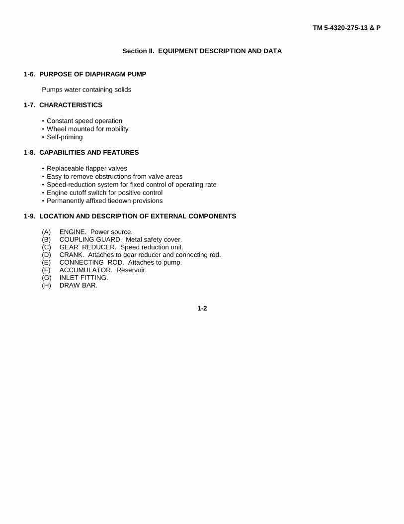
1-9. LOCATION AND DESCRIPTION OF EXTERNAL COMPONENTS
(A) ENGINE. Power source.(B) COUPLING GUARD. Metal safety cover.(C) GEAR REDUCER. Speed reduction unit.(D) CRANK. Attaches to gear reducer and connecting rod.(E) CONNECTING ROD. Attaches to pump.(F) ACCUMULATOR. Reservoir.(G) INLET FITTING.(H) DRAW BAR.
1-2
TM 5-4320-275-13 & P
(I) OUTLET FITTING.(J) WHEEL.(K) FRAME.(L) ENGINE MOUNT. Mounts engine to frame.(M) FUEL TANK. Mounts to engine.(N) ENGINE GUARD. Metal bumper for engine protection.(O) SUCTION HOSE.
1-3
TM 5-4320-275-13 & P
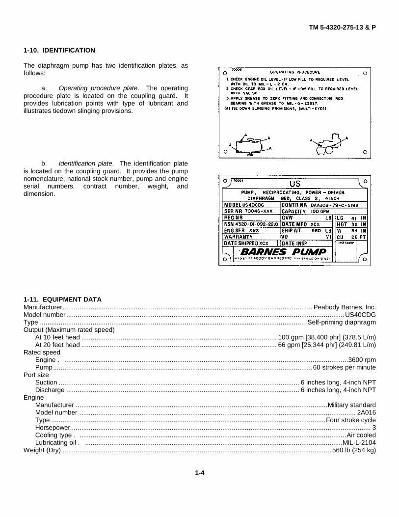
1-10. IDENTIFICATION
The diaphragm pump has two identification plates, asfollows:
a. Operating procedure plate. The operatingprocedure plate is located on the coupling guard. Itprovides lubrication points with type of lubricant andillustrates tiedown slinging provisions.
b. Identification plate. The identification plateis located on the coupling guard. It provides the pumpnomenclature, national stock number, pump and engineserial numbers, contract number, weight, anddimension.
EngineManufacturer ......................................................................................................................................Military standardModel number ................................................................................................................................................... 2A016Type ..................................................................................................................................................Four stroke cycleHorsepower................................................................................................................................................................ 3Cooling type . ..............................................................................................................................................Air cooledLubricating oil . .........................................................................................................................................MIL-L-2104
Weight (Dry) ............................................................................................................................................... 560 lb (254 kg)
1-4
TM 5-4320-275-13 & P
Section III. PRINCIPLES OF OPERATION
1-12. DIAPHRAGM PUMP
Consists of a gasoline engine and a wheel-mounted diaphragm pump. Power from the engine is transferred to the pumpthrough a floating coupling, gear reducer, crank, and connecting rod.
(A) ENGINE. Secured by engine mount to base assembly.(B) COUPLING GUARD. Serves as a safety device if. coupling should shear.(C) FLOATING COUPLING. Connects engine drive shaft to gear reducer input shaft.(D) GEAR REDUCER. Serves as a speed reducer to transfer engine power to the pump.(E) CRANK. Fitted to the gear reducer output shaft to change the circular motion of the shaft to lift-and-force
motion of the connecting rod.(F) CONNECTING ROD. Serves as the link between the crank and the pump diaphragm.(G) PUMP DIAPHRAGM. Changes the lift-and-force motion to suction and discharge pressure to move the
water through the pump.(H) ACCUMULATOR. Serves as a reservoir to provide a constant flow of inlet water and to eliminate priming.(I) BYPASS VALVE ASSEMBLY. The suction side bypass valve assembly starts to open when the pump
diaphragm begins the lift position and the discharge side bypass valve assembly starts to close. When the pump diaphragm starts moving to the force position, the suction side bypass assembly starts to close and thedischarge side bypass valve assembly starts to open.
(J) BOWL. Serves as the pump base to mount. the diaphragm and bypass valve assemblies. Provides directional control of pumped water.
(K) FRAME ASSEMBLY WITH DRAW BAR, ENGINE GUARD, AND WHEELS. Serves as a mobile support for all major assemblies.
1. Frame Assembly
2. Draw Bar
3. Engine Guard
4. Wheels
1-5/(1-6 blank)
TM 5-4320-275-13 & P
CHAPTER 2
OPERATING INSTRUCTIONS
Section I. DESCRIPTION AND USE OF OPERATOR'S CONTROLS AND INDICATORS
WARNING
Personal injury may result if the engine cutoff switch is not turned off during service ormaintenance.
The engine CUTOFF SWITCH attaches to the top of the engine and has two positions, OFF and ON. The switchcontrols the electrical current to the spark plug. In the ON position the electrical current will travel to the spark plug to runthe engine. In the OFF position the electrical current will not travel to the spark plug and the engine will not start.
2-1
TM 5-4320-275-13 & P
Section II. OPERATOR/CREW PREVENTIVE MAINTENANCECHECKS AND SERVICES (PMCS)
2-1. GENERAL
a. Before you operate. Always keep in mind the CAUTIONS and WARNINGS. Perform your before (B) PMCS.b. While you operate. Always keep in mind the CAUTIONS and WARNINGS. Perform your during (D) PMCS.c. After you operate. Be sure to perform your after (A) PMCS.d. If your equipment fails to operate. Troubleshoot with proper equipment. Report any deficiencies using the proper
forms; see TM 38-750.
2-2. PREVENTIVE MAINTENANCE CHECKS AND SERVICES
Table 2-1 lists the preventive maintenance checks and services which shall be performed at specified intervals by theoperator/crew.
Table 2-1. Operator/Crew Preventive Maintenance Checks and ServicesB - Before D - During A - After
IntervalItem Item to be Inspected. Equipment Is Not ReadyNo. B D A Procedure Available If
3 • Fuel Filter. Check for dirt orwater in fuel filter. Turnshutoff valve in to OFF.Loosen nut on bail offuel filter. Swing bailaside and remove fuelbowl. Dump fuel frombowl and wipe clean. Re-position fuel bowl andbail. Tighten nut on bail.Turn shutoff valve out toON.
2-22-2
TM 5-4320-275-13 & P
Table 2-1. Operator/Crew Preventive Maintenance Checks and Services - Continued
B - Before D - During A - After
IntervalItem Item to be Inspected. Equipment Is Not ReadyNo. B D A Procedure Available If
4 • Wheels. Check that cotter pin is securely holding wheel onaxle. Replace if missing. Put cotter pin through holein axle. Bend one end of cotter pin along contour ofaxle.
5 • Draw Bar. Check that hitch pins are in position throughends of draw bar.
6 • Fuel System. Check for loose lines and fittings. Tighten Fuel lines cannot beif necessary. tightened to stop
leaks.
2-3
TM 5-4320-275-13 & P
Table 2-1. Operator/Crew Preventive Maintenance Checks and Services - ContinuedB - Before D - During A - After
IntervalItem Item to be Inspected. Equipment Is Not ReadyNo. B D A Procedure Available If
7 • Pump Assembly. Check inlet and outlet pipe nipples for Water will not passobstructions. Remove any dirt or debris clogging through pump forthe pipe nipples. normal operation.
8 • Check Valves. Listen to operation of check valves. They Check valves do notmust open and close during normal operation. If open and/or close.the check valves do not work properly, the pumpwill not pump water.
9 • Accumulator. Check Pipe plug is missing.that pipe plugis on accumu-lator. Tightenpipe plug if itis loose.
2-4
TM 5-4320-275-13 & P
Table 2-1. Operator/Crew Preventive Maintenance Checks and Services - ContinuedB - Before D - During A - After
IntervalItem Item to be Inspected. Equipment Is Not ReadyNo. B D A Procedure Available If
10 • Pump Bowl. Check that drain plug is on pump bowl. Drain plug is missing.Tighten drain plug if it is loose.
11 • • • Suction Hose. Check for cracks or other damage. Suction hose leaks.Tighten connections if loose.
Section III. OPERATION UNDER USUAL CONDITIONS
2-3. ASSEMBLY AND PREPARATION FOR USEa. This pump comes fully assembled, ready for use after attaching appropriate suction and discharge hoses.b. Instructions for use are for information and guidance of personnel responsible for operation of the pump
assembly.c. The operator must know how to perform every operation of which the pump assembly is capable. The
following paragraphs contain instructions on starting and stopping the pump assembly, on operation of the pumpassembly, and on coordinating the basic motions to perform the specific tasks for which the equipment is designed.Since nearly every job presents a different problem, the operator may have to vary given procedures to fit the individualjob.
2-5
TM 5-4320-275-13 & P
2-4. INITIAL ADJUSTMENTS
Inspect pump assembly and engine for loose or missing hardware, corrosion, or obvious damage. Report any problemsto organizational maintenance.
2-5. OPERATING PROCEDURE
a. Selection and Preparation of Pump Site.
(1) Locate the pump on a level surface as close to the liquid supply as possible.
(2) Block the wheels of the pump assembly to prevent the pump from shifting during operation.
(3) When connecting suction hose to pump assembly, the suction lift of the pump must not exceed 25 feet(7.62 m).
b. Hose Installation.
NOTE
Use the shortest possible length of suction hose. Suction hose exceeding 20 feet (6.09 m) willreduce the pump capacity.
(1) Connect the suction hose to the accumulator pipe nipple. Use thread sealant on threaded connections.Tighten the suction hose with a spanner wrench NSN 5120-00-277-9077.
(2) If more than one length of hose is required, add additional lengths to end of first hose attached to pump.
2-6
TM 5-4320-275-13 & P
CAUTION
Strainer NSN 4730-00-203-6309 must be used on the end of the suction hose to prevent rocks andother unbreakable material from entering the pump. These could cause severe damage to thepump.
(3) Connect a hose to the discharge pipe nipple of the pump. The length of the discharge hose shall notexceed 50 feet (15.24 m).
(4) Make sure the end of the suction hose and strainer are completely submerged in the liquid to be pumped.Make sure the end of the discharge hose is free from any restrictions.
2-6. STARTING
WARNING
Severe burns, illness, or death may result if personnel fail to handle gasoline properly. Observethe following precautions:
• Do not inhale vapor.• Do not refuel a hot or running engine.• Do not refuel near open flame, sparks, or excessive heat.• Be certain fuel lines and connections are secure.• Do not overfill fuel tank.• Work in a well-ventilated area.
a. Perform checks shown on operating procedure plate.
(1) Check engine oil level.(2) Check gear box (gear reducer) oil.(3) Has connecting rod been lubricated?
b. Fill fuel tank.
2-7
TM 5-4320-275-13 & P
c. Prime fuel system if engine is new or seldom-used.
(1) Turn engine cutoff switch to OFF position.
(2) Pull starting rope.
(3) Allow starting rope to retract.
(4) Pull starting rope again.
(5) Allow to retract.
d. Turn engine cutoff switch ON.
e. Pull starting rope sharply.
f. Allow to retract.
g. Repeat steps e. and f., if necessary, until engine starts. (Cold engines are harder to start.)
h. If engine does not start after several attempts, see TROUBLESHOOTING PROCEDURES in Chapter 3 of thismanual.
2-7. OPERATION
NOTEIf the suction lift is less than 15 feet (4.57 m), pump priming is normally not necessary. If thesuction lift is greater than 15 feet (4.57 m), use a 15/16 inch wrench to remove pipe plug fromaccumulator and pour 2 gallons (7.6 liters) of water into the accumulator to prime the pump.Install the pipe plug with a 15/16 inch wrench.
The pump should prime within 2 minutes after the engine starts. If the pump does not prime, see TROUBLESHOOTINGPROCEDURES in Chapter 3 of this manual.
2-8
TM 5-4320-275-13 & P
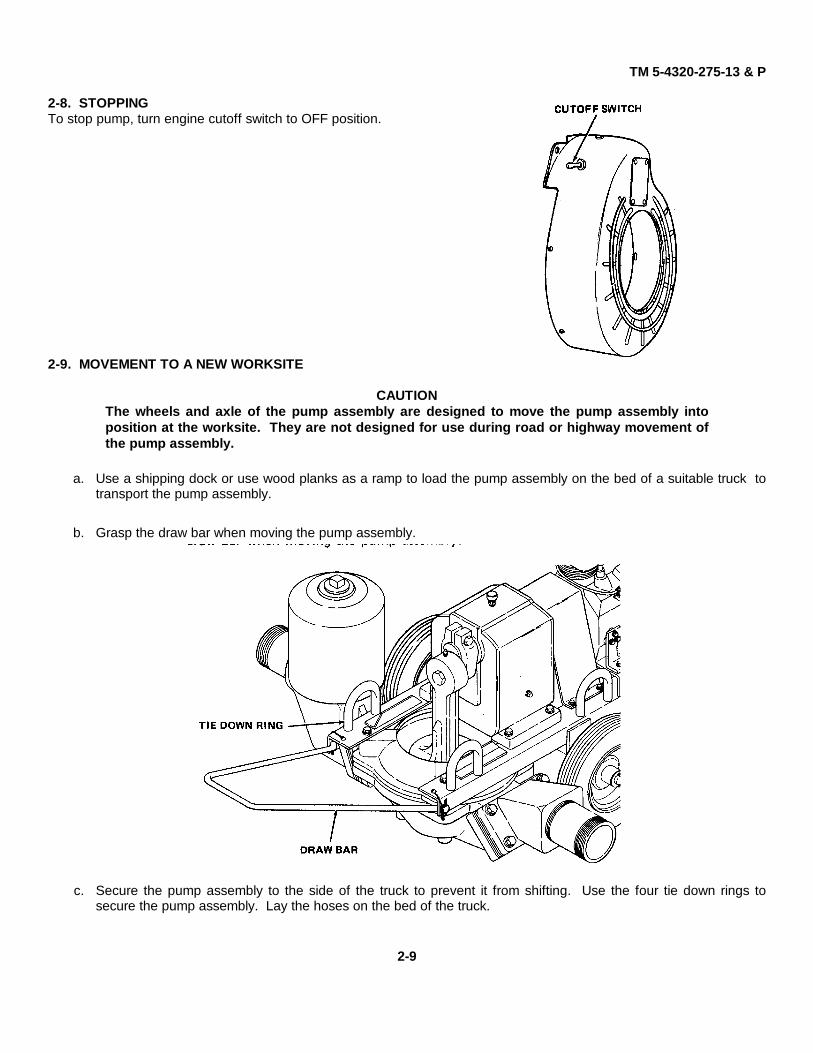
2-8. STOPPINGTo stop pump, turn engine cutoff switch to OFF position.
2-9. MOVEMENT TO A NEW WORKSITE
CAUTIONThe wheels and axle of the pump assembly are designed to move the pump assembly intoposition at the worksite. They are not designed for use during road or highway movement ofthe pump assembly.
a. Use a shipping dock or use wood planks as a ramp to load the pump assembly on the bed of a suitable truck totransport the pump assembly.
b. Grasp the draw bar when moving the pump assembly.
c. Secure the pump assembly to the side of the truck to prevent it from shifting. Use the four tie down rings tosecure the pump assembly. Lay the hoses on the bed of the truck.
2-9
TM 5-4320-275-13 & P
Section IV. OPERATION UNDER UNUSUAL CONDITIONS
2-10. OPERATION IN EXTREME COLD
a. Keep entire unit free of ice and snow.
b. Cover unit when not in use.
c. Shelter unit from weather, if possible.
d. Use proper engine oil for cold weather. See LO 5-4320-275-12.
e. Keep fuel tank full to prevent moisture condensation, which can freeze.
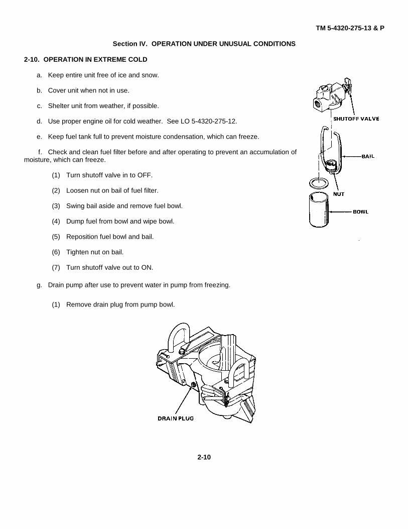
f. Check and clean fuel filter before and after operating to prevent an accumulation ofmoisture, which can freeze.
(1) Turn shutoff valve in to OFF.
(2) Loosen nut on bail of fuel filter.
(3) Swing bail aside and remove fuel bowl.
(4) Dump fuel from bowl and wipe bowl.
(5) Reposition fuel bowl and bail.
(6) Tighten nut on bail.
(7) Turn shutoff valve out to ON.
g. Drain pump after use to prevent water in pump from freezing.
(1) Remove drain plug from pump bowl.
2-10
TM 5-4320-275-13 & P
(2) Turn engine cutoff switch to OFF position.
(3) Pull starting rope sharply.
(4) Allow to retract.
(5) Repeat steps (3) and (4) above until all water is drained from pump bowl and accumulator.
(6) Replace and tighten drain plug.
2-11. OPERATION IN EXTREME HEAT
a. If possible, protect the pump assembly from direct rays of the sun.
b. Allow adequate space for ventilation. If the pump is operated in an enclosure, use a fan to circulate air.
c. Keep the engine shrouding and pump clean to provide proper heat transfer to the air.
d. Check that lubricants in the engine comply with LO 5-4320-275-12.
e. Although fluid flow can be stopped for short periods, avoid doing so in extreme heat for the fluid may boil in thepump bowl.
2-12. OPERATION IN HIGH ALTITUDES
The operating efficiency of both engine and pump diminishes at higher altitudes. Make sure that the engine is operatingat peak efficiency, providing the highest possible pump output. Adjust in accordance with TM 5-2805-257-14.
2-13. OPERATION IN SANDY OR DUSTY AREAS
a. When the pump is operated under sandy or dusty conditions, service engine air cleaner frequently in accordancewith TM 5-2805-257-14.
b. While filling the fuel tank, take care to prevent sand and dust from entering the fuel system.
2-11
TM 5-4320-275-13 & P
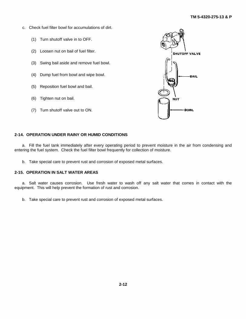
c. Check fuel filter bowl for accumulations of dirt.
(1) Turn shutoff valve in to OFF.
(2) Loosen nut on bail of fuel filter.
(3) Swing bail aside and remove fuel bowl.
(4) Dump fuel from bowl and wipe bowl.
(5) Reposition fuel bowl and bail.
(6) Tighten nut on bail.
(7) Turn shutoff valve out to ON.
2-14. OPERATION UNDER RAINY OR HUMID CONDITIONS
a. Fill the fuel tank immediately after every operating period to prevent moisture in the air from condensing andentering the fuel system. Check the fuel filter bowl frequently for collection of moisture.
b. Take special care to prevent rust and corrosion of exposed metal surfaces.
2-15. OPERATION IN SALT WATER AREAS
a. Salt water causes corrosion. Use fresh water to wash off any salt water that comes in contact with theequipment. This will help prevent the formation of rust and corrosion.
b. Take special care to prevent rust and corrosion of exposed metal surfaces.
2-12
TM 5-4320-275-13 & P
CHAPTER 3OPERATOR/CREW MAINTENANCE INSTRUCTIONS
Section I. LUBRICATION INSTRUCTIONS
No lubrication is authorized for operator/crew maintenance.
Section II. TROUBLESHOOTING PROCEDURES
3-1. TROUBLESHOOTING
a. Table 3-1 lists the common malfunctions which you may find during the operation or maintenance of thediaphragm pump or its components. Perform the tests/inspections and corrective actions in the order listed.
b. This manual cannot list all malfunctions that may occur, nor all tests or inspections and corrective actions. If amalfunction is not listed or is not corrected by listed corrective actions, notify your supervisor.
Table 3-1. Operator/Crew Troubleshooting
MALFUNCTIONTEST OR INSPECTION
CORRECTIVE ACTION
1. ENGINE FAILS TO START
Step 1. Check for empty fuel tank.
Fill fuel tank.
3-1
TM 5-4320-275-13 & P
Table 3-1. Operator/Crew Troubleshooting
MALFUNCTIONTEST OR INSPECTION
CORRECTIVE ACTION
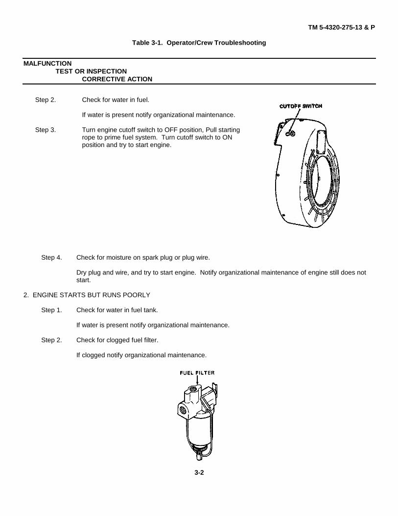
Step 2. Check for water in fuel.
If water is present notify organizational maintenance.
Step 3. Turn engine cutoff switch to OFF position, Pull startingrope to prime fuel system. Turn cutoff switch to ONposition and try to start engine.
Step 4. Check for moisture on spark plug or plug wire.
Dry plug and wire, and try to start engine. Notify organizational maintenance of engine still does notstart.
2. ENGINE STARTS BUT RUNS POORLY
Step 1. Check for water in fuel tank.
If water is present notify organizational maintenance.
Step 2. Check for clogged fuel filter.
If clogged notify organizational maintenance.
3-2
TM 5-4320-275-13 & P
Table 3-1. Operator/Crew Troubleshooting - Continued
MALFUNCTIONTEST OR INSPECTION
CORRECTIVE ACTION
3. PUMP FAILS TO PRIME
Step 1. Check for loose drain plug on pump bowl or pipe plug on accumulator.
If clogged notify organizational maintenance.
Step 2. Check for air leak at joint between accumulator and pump.
If air leaks are present notify organiza-tional maintenance.
Step 3. Check for air leak or blockage in suction line.
If air leaks or blockage is present notify organizational maintenance.
3-3
TM 5-4320-275-13 & P
Section Ill. MAINTENANCE PROCEDURES
3-2. INTRODUCTION
Operator/crew maintenance consists primarily of the following procedures:
• Checking pump and engine.
• Servicing fuel system.
• Cleaning pump assembly.
3-3. CHECKING PUMP AND ENGINE
Perform the visual and operational checks listed in table 3-2.
Table 3-2. Operational Check
OperationStep Normal Indication
Corrective Procedure
1 Check fuel tank.Tank should be full before operation.
Fill fuel tank.
2 Check for fuel leaks.Fuel system should be free of leaks.
Tighten any loose connections. Report leaking parts to organizationalmaintenance.
3 Check engine oil level when engine is hot.Oil must be between FULL and ADD levels.
Report low oil level to organizational maintenance.4 Check air cleaner.
Must not be clogged or torn.Report clogged or damaged air cleaner to organizational maintenance.
3-4
TM 5-4320-275-13 & P
Table 3-2. Operational Checks - Continued
OperationStep Normal Indication
Corrective Procedure
5 Check spark plug and wire.Must be free of moisture and dirt.
Wipe spark plug and wire clean and dry.6 Check frame assembly for cracked welds, bad wheels, or loose parts.
Frame assembly should be free of defects.Tighten loose parts. Notify organizational maintenance for replacementor direct support for repair.
7 Check tire pressure.Tire pressure should be 30 psi (207 kPa).
Inflate tires.8 Check pump hardware.
All hardware must be present and tight.Tighten loose hardware. Report missing hardware to organizationalmaintenance.
9 Check gear reducer for oil leaks.No oil leaks.
If oil leaks are present notify organizational maintenance.10 Start engine.
Should run smoothly.If engine does not run smoothly, stopengine immediately. Notify organiza-tional maintenance.
3-5
TM 5-4320-275-13 & P
Table 3-2. Operational Checks - Continued
OperationStep Normal Indication
Corrective Procedure
11 Check for abnormal noises.Unit should run quietly and smoothly.
If noises are evident notify organizational maintenance.12 Check drive operation.
Operation should be smooth.Report noisy operation to organizational maintenance.
13 Check pump for leaks or rust.Pump should be free of leaks and rust.
Report leaks or rust condition to organizational maintenance.14 Check pump output.
Fluid flow should be constant.If flow is not constant, stop engine and clear pump inlet and outlet ofobstacles.
3-4. SERVICING FUEL SYSTEM
Check and clean fuel filter before and after operating to prevent an accumulation of moisture, which can freeze.
a. Turn shutoff valve in to OFF.
b. Loosen nut on bail of fuel filter.
c. Swing bail aside and remove fuel bowl.
d. Dump fuel from bowl and wipe bowl.
e. Reposition fuel bowl and bail.
f. Tighten nut on bail.
g. Turn shutoff valve out to ON.
3-6
TM 5-4320-275-13 & P
3-5. CLEANING
CAUTIONBecause of the corrosive action of salt water, use fresh water to wash off any salt water thatcomes in contact with the equipment. This will help prevent the formation of rust andcorrosion.
Before storing pump, clean inside and outside of pump with fresh water; wipe exterior dry.
3-7/(3-8 blank)
TM 5-4320-275-13 & P
CHAPTER 4
ORGANIZATIONAL MAINTENANCE INSTRUCTIONS
This chapter contains the following frequently used maintenance information:
a. Information on repair parts, special tools, TMDE, and support equipment
b. Instructions for service upon receipt of the pump assembly
c. Lubrication
d. Operational checks
e. Preventive maintenance checks and services (PMCS)
f. Troubleshooting
g. Maintenance procedures
The symptom index on page 4-14 is a guide to the troubleshooting information. There is also an index to themaintenance procedures on page 4-23.
Section Title Page
I Repair Parts, Special Tools, TMDE, and Support Equipment............................... 4-1II Service Upon Receipt.......................................................................................... 4-2
III Operational Checks ............................................................................................. 4-5IV Preventive Maintenance Checks and Services .................................................... 4-7V Troubleshooting................................................................................................... 4-14
VI Maintenance Procedures ..................................................................................... 4-23VII Preparation for Shipment or Storage.................................................................... 4-84
Section I. REPAIR PARTS, SPECIAL TOOLS, TMDE, AND SUPPORT EQUIPMENT
4-1. COMMON TOOLS AND EQUIPMENT
For authorized common tools and equipment, refer to the Modified Table of Organization and Equipment (MTOE)applicable to your unit.
4-2. SPECIAL TOOLS, TMDE, AND SUPPORT EQUIPMENT
No special tools, TMDE, or support equipment is required for this pump.
4-3. REPAIR PARTS
Repair parts are listed and illustrated in Appendix C of this manual.
4-1
TM 5-4320-275-13 & P
Section II. SERVICE UPON RECEIPT
4-4. SERVICE UPON RECEIPT OF MATERIEL- PUMP ASSEMBLY
Location Item Action Remarks1. Top of engine Fuel tank Ensure tank is in good condition
and not leaking.
2. Side of engine Fuel filter Check that fuel filter is present andin good condition.
3. Side of engine Fuel lines Check that fuel lines are present, ingood condition, and secure.
4. Top of engine Cutoff switch Check that switch is present and ingood condition.
5. Accumulator Pipe plug Check that pipe plug is present andsecure.
6. Bottom of Drain plug Check that drain plug is present andpump secure.
7. Pump area Check valves Operate check valves by hand to becertain they open and close.
8. Engine Various Refer to engine manual. See TM 5-2805-257-14.
4-5. SERVICING AND ADJUSTMENT OF EQUIPMENT
a. Preliminary. No servicing or adjustment is required for the pump. Refer to TM 5-2805-257-14 for servicing andadjusting the engine.
b. Lubrication. Refer to LO 5-4320-275-12 (figure 4-1) for lubrication points, intervals, and detailed instructions.
4-2
TM 5-4320-275-13 & P
Figure 4-1. Lubrication Order (Sheet 1 of 2)
4-3
TM 5-4320-275-13 & P
Figure 4-1. Lubrication Order (Sheet 2 of 2)
4-4
TM 5-4320-275-13 & P
Section III. OPERATIONAL CHECKS
4-6. OPERATIONAL CHECKS
Perform the visual and operational checks listed in table 4-1.
Table 4-1. Operational Checks
OperationStep Normal Indication
Corrective Procedure
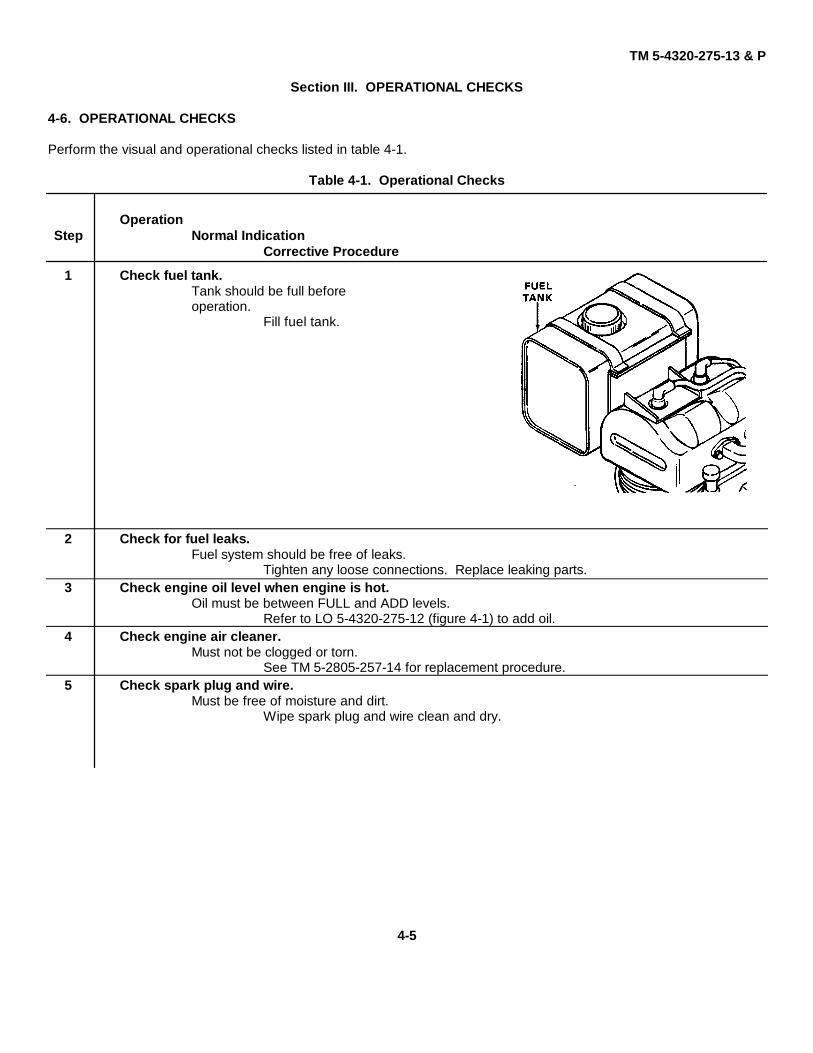
1 Check fuel tank.Tank should be full beforeoperation.
Fill fuel tank.
2 Check for fuel leaks.Fuel system should be free of leaks.
Tighten any loose connections. Replace leaking parts.3 Check engine oil level when engine is hot.
Oil must be between FULL and ADD levels.Refer to LO 5-4320-275-12 (figure 4-1) to add oil.
4 Check engine air cleaner.Must not be clogged or torn.
See TM 5-2805-257-14 for replacement procedure.5 Check spark plug and wire.
Must be free of moisture and dirt.Wipe spark plug and wire clean and dry.
4-5
TM 5-4320-275-13 & P
Table 4-1. Operational Checks - Continued
OperationStep Normal Indication
Corrective Procedure
6 Check frame assembly for cracked welds, bad wheels, or loose parts.Frame assembly and wheels should be free of defects.
Tighten loose parts. Replace defective parts or send to direct supportfor repair.
7 Check tire pressure.Tire pressure should be 30 psi (207 kPa).
Inflate tires.8 Check pump hardware.
All hardware must be present and tight.Install and/or tighten hardware.
9 Check gear reducer for oil leaks.No oil leaks.
Replace gear reducer or send to direct support for repair.
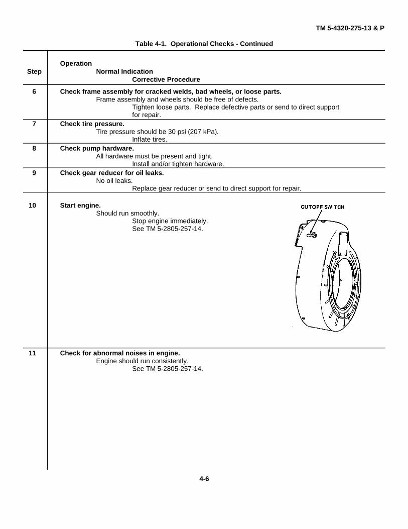
10 Start engine.Should run smoothly.
Stop engine immediately.See TM 5-2805-257-14.
11 Check for abnormal noises in engine.Engine should run consistently.
See TM 5-2805-257-14.
4-6
TM 5-4320-275-13 & P
Table 4-1. Operational Checks - Continued
OperationStep Normal Indication
Corrective Procedure
12 Check drive operation.Operation should be smooth.
Replace noisy parts.
13 Check pump for leaks or rust.Pump should be free of leaks and rust.
Replace defective parts.
14 Check pump output.Pump should deliver approximately 100 gpm (38400 phr).
Clear pump inlet and outlet of obstacles.
Section IV. PREVENTIVE MAINTENANCE CHECKS AND SERVICES
4-7. PREVENTIVE MAINTENANCE CHECKS AND SERVICES
Table 4-2 lists the preventive maintenance checks and services which shall be performed at specified intervals byorganizational maintenance personnel. It includes and expands upon the preventive maintenance services performed byoperator/crew maintenance and includes additional services which are allocated to organizational maintenance.
NOTEItem numbers in the following table shall be used as source of item numbers for the TMNumber Column on DA Form 2404, Equipment Inspection and Maintenance Worksheet, inrecording results of PMCS.
4-7
TM 5-4320-275-13 & P
Table 4-2. Organizational Preventive Maintenance Checks and Services
M - Monthly Q - Quarterly S - Semiannually
IntervalItem Item to beNo. M Q S Inspected Procedures
1 • Engine oil. Check that engine oil has been changed at required interval.See LO 5-4320-275-12 (figure 4-1).
2 • Fuel system. Check for leaks.
3 • Fuel filter. Clean fuel filter. Turn shutoff valein to OFF. Loosen nut on bail offuel filter. Swing bail aside and re-move fuel bowl. Dump fuel frombowl and wipe clean. Repositionfuel' bowl and bail. Tighten nut orbail. Turn shutoff valve out to ON.
4 • Wheels. Check that cotter pinis securely holdingwheel on axle. Replaceif missing. Put cotterpin through hole inaxle. Bend one end ofcotter pin along thecontour of the axle.
5 • Wheels. Clean and check for damage. Check that wheel bearings havebeen lubricated in accordance with LO 5-4320-275-12(figure 4-1).
4-8
TM 5-4320-275-13 & P
Table 4-2. Organizational Preventive Maintenance Checks and Services - Continued
M - Monthly Q - Quarterly S - Semiannually
IntervalItem Item to beNo. M Q S Inspected Procedures
6 • Tires. Inspect tires for proper inflation and condition. Repair or re-place tire assembly as necessary. Inflate tires to 30 psi(207 kPa).
7 • Draw bar. Check that hitch pins are in position through ends of drawbar.
8 • Engine guard. Check that cap screws holding engine guard to frame aretight.
4-9
TM 5-4320-275-13 & P
Table 4-2. Organizational Preventive Maintenance Checks and Services - Continued
M - Monthly Q - Quarterly S - Semiannually
IntervalItem Item to beNo. M Q S Inspected Procedures
9 • Engine screws. Check that capscrews holdingengine to enginemount are tight.
10 • Frame assembly. Check for cracks or broken welds.
11 • Pump assembly. Check inlet and outlet pipe nipples for leaks, cracks, ordamage. Replace any damaged pipe nipple.
12 • Check valves. Start the engine and listen to the operation of the checkvalves. Check valves must open and close during normal opera-tion. If check valves do not open and close, check for anobstruction in the accumulator or the discharge port, then
4-10
TM 5-4320-275-13 & PTable 4-2. Organizational Preventive Maintenance Checks and Services - Continued
M - Monthly Q - Quarterly S - Semiannually
IntervalItem Item to beNo. M Q S Inspected Procedures
recheck. If one check valve does not operate properly, replacethe check valve in accordance with paragraph 4-19 and 4-20.If both check valves do not operate properly, replace thediaphragm in accordance with paragraph 4-21.
13 • Accumulator. Check that pipe plug on accumulator is tight.
14 • Pump bowl. Check that drain plug on pump bowl is tight.
4-11
TM 5-4320-275-13 & P
Table 4-2. Organizational Preventive Maintenance Checks and Services - Continued
M - Monthly Q - Quarterly S - Semiannually
IntervalItem Item to beNo. M Q S Inspected Procedures
15 Pump screws. Check that cap screwsholding pump to frameare tight.
16 Diaphragm Check that nutsclamp nuts. holding diaphragm
between con-necting rod assem-bly and clamp aretight.
4-124-12
TM 5-4320-275-13 & P
Table 4-2. Organizational Preventive Maintenance Checks and Services - Continued
M - Monthly Q - Quarterly S - Semiannually
IntervalItem Item to beNo. M Q S Inspected Procedures
17 • Diaphragm. Check that diaphragm is not torn. Replace a torn diaphragm inaccordance with paragraph 4-21.
18 • Gear reducer Check that cap screws and nuts holding gear reducer to framescrews. are tight.
19 • Gear reducer. Check that gear reducer runs quietly and without restriction.Replace the gear reducer in accordance with paragraph 4-26if it is noisy or if shaft rotation is restricted.
20 • Gear reducer. Check that gear reducer oil has been changed at requiredinterval. See LO 5-4320-275-12 (figure 4-1).
4-13
TM 5-4320-275-13 & PSection V. TROUBLESHOOTING
4-8. TROUBLESHOOTING
a. Table 4-3 contains troubleshooting information for locating and correcting most of the operating troubles whichare the responsibility of organizational maintenance. Each malfunction for an individual component, unit, or system isfollowed by a list of tests or inspections which will help you to determine probable causes and corrective actions to take.Perform the tests/inspections and corrective actions in the order listed.
b. This manual cannot list all malfunctions that may occur, nor all tests or inspections and corrective actions. If amalfunction is not listed or is not corrected by listed corrective actions, notify your supervisor.
c. Only those functions within the scope of organizational maintenance are listed. For troubleshooting procedureswithin the scope of operator/crew maintenance, refer to table 3-1.
4-9. SYMPTOM INDEX
Refer to the Symptom Index below. Locate the malfunction which is the same, or most nearly the same, as the troubleyou are having with the pump. The Symptom Index lists the first page of troubleshooting information for thatmalfunction. Follow the steps one by one, and perform the corrective actions listed.
MalfunctionNumber Description Page
1 Engine fails to start 4-152 Engine starts, but stalls 4-183 Pump fails to prime, or has low output (engine running well) 4-214 Suction leak between accumulator and bowl 4-22
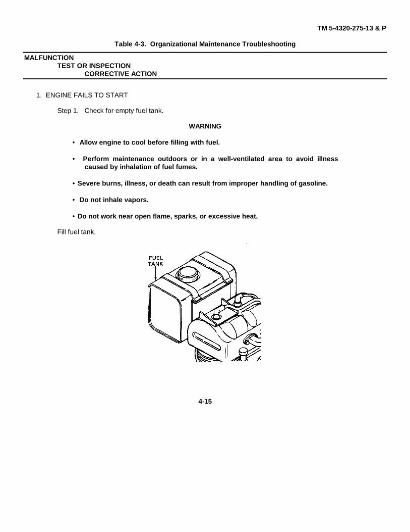
• Perform maintenance outdoors or in a well-ventilated area to avoid illnesscaused by inhalation of fuel fumes.
• Severe burns, illness, or death can result from improper handling of gasoline.
• Do not inhale vapors.
• Do not work near open flame, sparks, or excessive heat.
Fill fuel tank.
4-15
TM 5-4320-275-13 & P
Table 4-3. Organizational Maintenance Troubleshooting - Continued
MALFUNCTIONTEST OR INSPECTION
CORRECTIVE ACTION
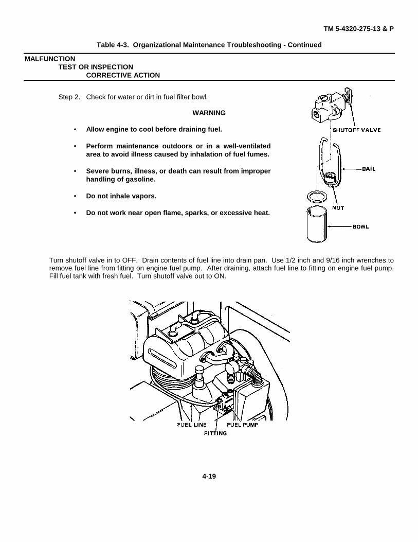
Step 2. Check for water or dirt in fuel filter bowl.
WARNING
• Allow engine to cool before draining fuel.
• Perform maintenance outdoors or in a well-ventilatedarea to avoid illness caused by inhalation of fuel fumes.
• Severe burns, illness, or death can result from improperhandling of gasoline.
• Do not inhale vapors.
• Do not work near open flame, sparks, or excessive heat.
Turn shutoff valve in to OFF. Drain contents of fuel line into drain pan. Use 1/2 inch and 9/16 inch wrenches toremove fuel line from fitting on engine fuel pump. After draining, attach fuel line to fitting on engine fuel pump.Fill fuel tank with fresh fuel. Turn shutoff valve out to ON.
4-164-16
TM 5-4320-275-13 & P
Table 4-3. Organizational Maintenance Troubleshooting - Continued
MALFUNCTIONTEST OR INSPECTION
CORRECTIVE ACTION
Step 3. Check for clogged fuel line.
WARNING
• Allow engine to cool before filling with fuel.
• Perform maintenance outdoors or in a well-ventilated area to avoid illnesscaused by inhalation of fuel fumes.
• Severe burns, illness, or death can result from improper handling of gasoline.
• Do not inhale vapors.
• Do not work near open flame, sparks, or excessive heat.
Turn shutoff valve in to OFF. Drain contents of fuel line into drain pan. Use 1/2 inch and 9/16 inch wrenches toremove fuel line from fitting on engine fuel pump. Use 1/2 inch wrench to remove fuel line from fuel filter.Remove clogged material from fuel line by gently probing with a blunt end rigid wire. If the clogging materialcannot be removed, or if the fuel line is damaged, replace the fuel line. Use 1/2 inch wrench to attach fuel line tofuel filter. Attach fuel line to fitting on engine fuel pump. Turn shutoff valve out to ON.
4-17
TM 5-4320-275-13 & P
Table 4-3. Organizational Maintenance Troubleshooting - Continued
MALFUNCTIONTEST OR INSPECTION
CORRECTIVE ACTION
2. ENGINE STARTS, BUT STALLS
Step 1. Check for empty fuel tank.
WARNING
• Allow engine to cool before filling with fuel.• Perform maintenance outdoors or in a well-ventilated area to avoid illness
caused by inhalation of fuel fumes.• Severe burns, illness, or death can result, from improper handling of gasoline.• Do not inhale vapors.• Do not work near open flame, sparks, or excessive heat.
Fill fuel tank.
4-18
TM 5-4320-275-13 & P
Table 4-3. Organizational Maintenance Troubleshooting - Continued
MALFUNCTIONTEST OR INSPECTION
CORRECTIVE ACTION
Step 2. Check for water or dirt in fuel filter bowl.
WARNING
• Allow engine to cool before draining fuel.
• Perform maintenance outdoors or in a well-ventilatedarea to avoid illness caused by inhalation of fuel fumes.
• Severe burns, illness, or death can result from improperhandling of gasoline.
• Do not inhale vapors.
• Do not work near open flame, sparks, or excessive heat.
Turn shutoff valve in to OFF. Drain contents of fuel line into drain pan. Use 1/2 inch and 9/16 inch wrenches toremove fuel line from fitting on engine fuel pump. After draining, attach fuel line to fitting on engine fuel pump.Fill fuel tank with fresh fuel. Turn shutoff valve out to ON.
4-19
TM 5-4320-275-13 & P
Table 4-3. Organizational Maintenance Troubleshooting - Continued
MALFUNCTIONTEST OR INSPECTION
CORRECTIVE ACTION
Step 3. Check for clogged fuel line.
WARNING
• Allow engine to cool before filling with fuel.• Perform maintenance outdoors or in a well-ventilated area to avoid illness
caused by inhalation of fuel fumes.• Severe burns, illness, or death can result from improper handling of gasoline.• Do not inhale vapors.• Do not work near open flame, sparks, or excessive heat.
Turn shutoff valve in to OFF. Drain contents of fuel line into drain pan. Use 1/2 inch and 9/16 inch wrenches toremove fuel line from fitting on engine fuel pump. Use 1/2 inch wrench to remove fuel line from fuel filter.Remove clogged material from fuel line by gently probing with a blunt end rigid wire. If the clogging materialcannot be removed, or if the fuel line is damaged, replace the fuel line. Use 1/2 inch wrench to attach fuel line tofuel filter. Attach fuel line to fitting on engine fuel pump.
4-20
TM 5-4320-275-13 & P
Table 4-3. Organizational Maintenance Troubleshooting - Continued
MALFUNCTIONTEST OR INSPECTION
CORRECTIVE ACTION
3. PUMP FAILS TO PRIME, OR HAS LOW OUTPUT (ENGINE RUNNING WELL)
Step 1. Check for loose drain plug on bowl.Use 5/8 inch wrench to tighten drain plug.
Step 2. Check for loose pipe plug on accumulator.
Use 1-1/4 inch wrench to tighten pipe plug.
4-21
TM 5-4320-275-13 & P
Table 4-3. Organizational Maintenance Troubleshooting - Continued
MALFUNCTIONTEST OR INSPECTION
CORRECTIVE ACTION
Step 3. Check for leaks in suction hose by inspecting all parts of suction hose for cracks or other damage.
4. SUCTION LEAK BETWEEN ACCUMULATOR AND BOWLStep 1. Check for loose screws holding accumulator on bowl.
Tighten cap screws. Use 3/4 inch socket with a torque wrench and tighten the four cap screws to a torque of 40ft lb (54 N•m).
Step 2. Check for bad gasket between accumulator and check valve assembly.
Replace gasket. Use 3/4 inch socket and handle to remove four cap screws holding accumulator on bowl. Remove accumulator and gasket. Install new gasket between accumulator and check valve assembly. Use 3/4 inch socket with a torque wrench and tighten the fourcap screws to a torque of 40 ft lb (54 N•m). Use Loctite (Item 7, Appendix D) on threads.
4-224-22
TM 5-4320-275-13 & P
Table 4-3. Organizational Maintenance Troubleshooting - Continued
MALFUNCTIONTEST OR INSPECTION
CORRECTIVE ACTION
Step 3. Check for defective check valve assembly on accumulator side of bowl.
Replace check valve assembly. Use 3/4 inch socketand handle to remove four cap screws holdingaccumulator on bowl. Remove accumulator, gasket,and check valve assembly. Install a new gasket andcheck valve assembly. Use 3/4 inch socket with atorque wrench and tighten the four cap screws to atorque of 40 ft lb (54 N.m). Use Loctite (Item 7,Appendix D) on threads.
4-10. GENERAL INSTRUCTIONSMost maintenance instructions in this section will list resources required, personnel required, and equipment condition forthe start of the procedure. Note the following:
• Resources required are not listed unless they apply to the procedure.• Personnel required are listed only if the task requires more than one. If PERSONNEL is not listed, it means one
person can do the task.• The normal standard equipment condition to start a maintenance task is engine stopped and cutoff switch off.
EQUIPMENT CONDITION is not listed unless some other condition is required besides the power being off.
4-11. PUMP ASSEMBLY INSPECTIONComponent Acceptable Repairable Not Repairable
Personnel Required: 2Wrench, 7/16 inch, or Mechanic will assist in lifting engine.Socket, 7/16 inch and handle ReferencesWrench, 9/16 inch, or NoneSocket, 9/16 inch and handle Troubleshooting ReferencesKey, hex drive, 5/32 inch NonePuller, mechanical, gear and bearing Special Environmental Conditions
Well-ventilated area required whenShop equipment, automotive gasoline is handled.maintenance and repair,NSN 4910-00-754-0654 General Safety Instructions
Torque wrench, 0-175 ft lb Allow engine to cool before performing(0-250 N•m) any maintenance.
4-25
TM 5-4320-275-13 & P
ENGINE (CONT)
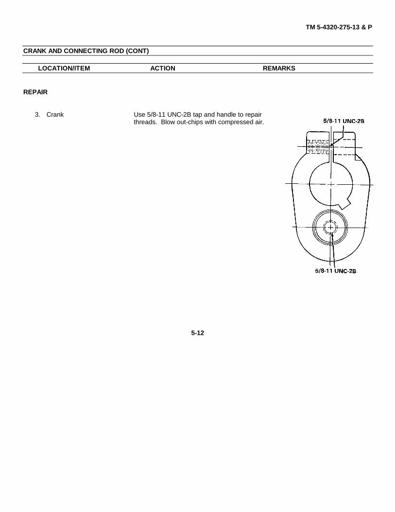
LOCATION/ITEM ACTION REMARKS
REMOVAL
WARNING
Severe burns, illness, or death can result from improper handling of gasoline.When working with gasoline:
•· Do not inhale vapors.•· Work in well-ventilated area.•· Do not work near open flame, sparks, or excessive heat.
1. Fuel filter Turn shutoff valve in to OFF.
2. Engine guard Loosen 4 cap screws (1) with 9/16 inch wrench.Pull engine guard (2) away from engine.
4-264-26
TM 5-4320-275-13 & P
ENGINE (CONT)
LOCATION/ITEM ACTION REMARKS
3. Coupling guard Use 7/16 inch socket and handle to remove 4cap screws (1) and lockwashers (3). Hold nuts(2) with 7/16 inch wrench. Remove couplingguard (4) by lifting straight up.
4. Engine Use 7/16 inch wrench to re-move 12 cap screws (1) andlockwashers (2) from engine(6). Slide engine away fromgear reducer (3). Use a 5/32inch hex key to loosen set-screw in engine coupling (4)half. Remove coupling halffrom engine. Remove anddiscard key (5). Lift engine(6).off frame (7).
NOTEIt may be necessary to use a mechanical gear and bearing, puller to removecoupling half from engine.
4-274-27
TM 5-4320-275-13 & P
ENGINE (CONT)
LOCATION/ITEM ACTION REMARKS
DISASSEMBLY
5. Engine This manual contains no engine disassembly instruc-tions. See TM 5-2805-257-14 for engine disassembly.
CLEANING
6. Engine This manual contains no engine cleaning instructions.See TM 5-2805-257-14 for engine cleaning.
INSTALLATION
7. Engine Install new key (5) in engine shaft groove. Installhalf of coupling (4) onto key (5) and engine shaft.Use a 5/32 inch hex key to tighten setscrew oncoupling (4). Slide engine (6) toward gear reducer(3) and align coupling halves.
8. Torque cap Install lockwashers (2) on cap screws (1). Usescrews Loctite on threads. Tighten 12 cap screws to 4 ft
lb (5 N•m).
4-28
TM 5-4320-275-13 & P
ENGINE (CONT)
LOCATION/ITEM ACTION REMARKS
9. Coupling guard Position coupling guard (4) over coupling andalign holes with frame holes. Install 4 cap screws(1), lockwashers (3), and nuts (2). Use Loctiteon threads. Hold nuts (2) with 7/16 inch wrenchand tighten cap screws (1) with 7/16 inch socketand handle.
10. Engine guard Slide engine guard (2) toward engine. Positionengine guard so it is clear of engine startingpulley. Tighten cap screws (1).
11. Torque cap Tighten 4 cap screws (1) to 4 ft lb (5 N•m).screws
12. Fuel filter Turn shutoff valve out to ON.
4-29
TM 5-4320-275-13 & P
4-13. FUEL FILTER
This task covers:a. Shutting off fuel supply. b. Disassembling fuel filter.c. Cleaning fuel filter. d. Assembling fuel filter
INITIAL SETUP
Test Equipment Troubleshooting ReferencesNone Malfunction 1, step 2
Tools Malfunction 2, step 2None
Special Environmental ConditionsMaterials/Parts
Fuel filter (Appendix C, item 15, fig. 2) Well-ventilated area required when gasolineor solvent is handled.
Dry cleaning solvent, P-D-680References General Safety Instructions
None None
4-30
TM 5-4320-275-13 & P
FUEL FILTER (CONT)
LOCATION/ITEM ACTION REMARKS
DISASSEMBLY
WARNING
Severe burns, illness, or death can result from improper handling of gaso-line. When working with gasoline:
• Do not inhale vapors.• Work in well-ventilated area.• Do not work near open flame, sparks, or excessive heat.
1. Shutoff valve Turn shutoff valve (1) in to OFF.
2. Nut Loosen nut (2) on bail.
3. Bail and bowl Swing bail (3) aside and remove fuel bowl (4).
CLEANING
WARNING
Clean parts in a well-ventilated area. Avoid inhalation of solvent fumes andprolonged exposure of skin to cleaning solvent. Wash exposed skin thoroughly.Dry cleaning solvent (fed. spec. P-D-680) used to clean parts is potentiallydangerous to personnel and property. Do not use near open flame or excessiveheat. Flash point of solvent is 100° F (38° C).
4. Bowl Clean inside of bowl with dry cleaning solvent,P-D-680, and wipe dry.
4-31
TM 5-4320-275-13 & P
FUEL FILTER (CONT)
LOCATION/ITEM ACTION REMARKS
5. Exterior of Clean outside of fuel filter with dry cleaningfuel filter solvent, P-D-680. Use a soft-bristle brush to re-
move caked dirt.
ASSEMBLY
CAUTION
Be certain top of bowl is clean of any foreign material when assembling on fuelfilter.
6. Bowl and Set bowl (4) on fuel filter and swing bail (3) to holdbail bowl.
7. Nut Tighten nut (2) on bail.
8. Shutoff valve Turn shutoff valve (1) out to ON.
4-32
TM 5-4320-275-13 & P
4-14. FUEL TANK
This task covers:a. Draining fuel tank b. Removing fuel tankc. Strainer replacement d. Installing fuel tank
INITIAL SETUP
Test Equipment ReferencesNone None
Troubleshooting ReferencesTools
NoneTool kit, general mechanics automotive,NSN 5180-00-177-7033 Equipment Condition
Screwdriver, flat tip Fuel filter shutoff valve OFF.Wrench, 7/16 inchWrench, 3/8 inch, or Special Environmental ConditionsSocket, 3/8 inch, and handleWrench, 1/2 inch Well-ventilated area required when gasolineWrench, 9/16 inch is handled.Drain pan General Safety Instructions
WARNING• Be certain fuel tank is empty before
removing from engine.Materials/Parts • Allow engine to cool before performing
Fuel tank (Appendix C, item 4, fig any maintenance.Loctite (Item 7, Appendix D) • Perform maintenance outdoors or in a
well-ventilated area to avoid illnesscaused by inhalation of fuel fumes.
4-33
TM 5-4320-275-13 & P
FUEL TANK (CONT)
LOCATION/ITEM ACTION REMARKS
REMOVAL
WARNING
Severe burns, illness, or death can result from improper handling of gasoline.When working with gasoline:
• Do not inhale vapors.• Work in well-ventilated area.• Do not work near open flame, sparks, or excessive heat.
1. Pipe plug Drain contents of fuel tank into drain pan. Use 7/16inch wrench to remove pipe plug.
2. Cap Remove fuel tank cap.
4-34
TM 5-4320-275-13 & P
FUEL TANK (CONT)
LOCATION/ITEM ACTION REMARKS
3. Fuel line Drain contents of fuel line into drain pan. Use1/2 inch wrench to hold fuel line assembly (1).Use a 9/16 inch wrench to turn swivel fittingon engine fuel pump. Then remove fuel lineassembly (1) from fuel filter (2) with a 1/2inch wrench.
4. Remove screws Use screwdriver to hold two screws (5). Use3/8 inch wrench to remove two nuts (3). Re-move lockwashers (4).
5. Remove straps Remove two straps (6) from bracket (7). Re-move fuel tank (8).
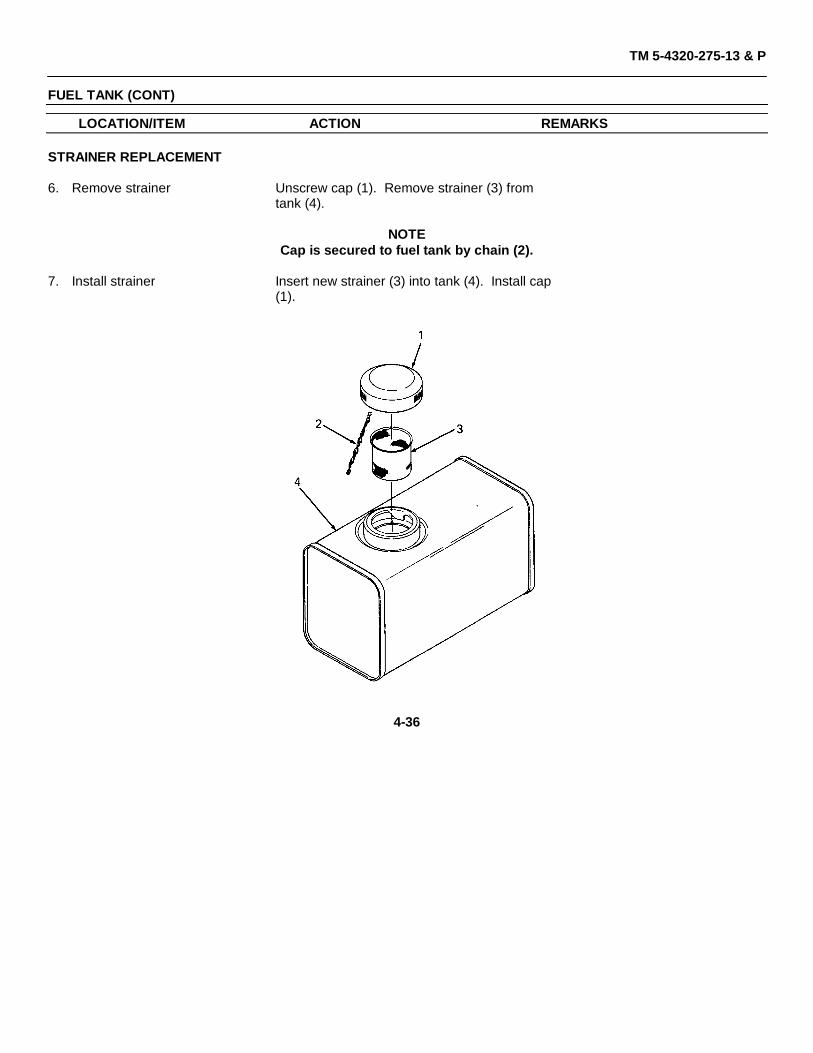
7. Install strainer Insert new strainer (3) into tank (4). Install cap(1).
4-36
TM 5-4320-275-13 & P
FUEL TANK (CONT)
LOCATION/ITEM ACTION REMARKS
INSTALLATION
8. Install straps Slide straps (6) over each end of the fuel tank(8). Install straps (6) with fuel tank (8) onbracket (7)
9. Install screws Insert screws (5) through ends of straps (6).Install lockwashers (4) and nuts (3). Use Loctiteon threads.
10. Tighten screws Use 3/8 inch wrench to hold nuts (3). Usescrewdriver to tighten each screw (5).
4-37
TM 5-4320-275-13 & P
FUEL TANK (CONT)
LOCATION/ITEM ACTION REMARKS
11. Fuel line Use 1/2 inch wrench to attach fuel line assembly(1) to fuel filter (2). Then attach fuel line assem-bly to engine fuel pump. Use a 1/2 inch wrenchto hole fuel line assembly and a 9/16 inch wrenchto turn swivel fitting on engine fuel pump.
12. Cap Install fuel tank cap.
13. Pipe plug Use 7/16 inch wrench to install pipe plug. UseLoctite on threads.
4-38
TM 5-4320-275-13 & P
4-15. FUEL LINE
This task covers:a. Removalb. Installation
INITIAL SETUP
Test Equipment Equipment ConditionNone Fuel filter shutoff valve turned to OFF,
shutoff switch off.
ToolsTool kit, general mechanics automotive,NSN 5180-00-177-7033 Special Environmental Conditions
Wrench 1/2 inch Well-ventilated area required whenWrench, 9/16 inch gasoline is handled.
Drain panGeneral Safety Instructions
Materials/PartsFuel line assembly (Appendix WARNINGC, item 12, fig.2)
• Allow engine to cool before performingany maintenance.
ReferencesNone • Perform maintenance outdoors or in a
well-ventilated area to avoid illnesscaused by inhalation of fuel fumes.
Troubleshooting ReferencesNone
4-39
TM 5-4320-275-13 & P
FUEL TANK (CONT)
LOCATION/ITEM ACTION REMARKS
REMOVAL
WARNING
Severe burns, illness, or death can result from improper handling of gaso-line. When working with gasoline:
• Do not inhale vapors.• Work in well-ventilated area.• Do not work near open flame, sparks, or excessive heat.
1. Drain line Drain contents of fuel line into drain pan. Use 1/2inch and 9/16 inch wrenches to remove fuel linefrom fitting on engine fuel pump.
2. Remove line Use 1/2 inch wrench to remove fuel line from fuelfilter.
INSTALLATION
3. Install line Use 1/2 inch wrench to install fuel line to fuelfilter.
4. Attach line Use 1/2 inch and 9/16 inch wrenches to installto engine fuel line to fitting on engine fuel pump.
4-40
TM 5-4320-275-13 & P
4-16. FRAME ASSEMBLY
This task covers:a. Disassembly b. Inspection c. Cleaning.d. Assembly
INITIAL SETUP
Test Equipment U-Bolt (Appendix C, item 16, fig.3)None
Cleaning solvent, P-D-680Screwdriver, Phillips, crossPliers, long, round nose ReferencesWrench, 1/2 inch, or NoneSocket, 1/2 inch, and handleWrench, 9/16 inch, or Troubleshooting ReferencesSocket, 9/16 inch, and handle None
Shop equipment, automotive Equipment Conditionmaintenance and repair, Gear reducer, pump, and wheel assembliesNSN 4910-00-754-0654 removed for access to frame assembly.
Torque wrench, 0-175 ft lb (0-250 N•m) Special Environmental ConditionsWell-ventilated area required when
Materials/Parts solvent is used.Draw bar (Appendix C, item 1, fig.3)Engine guard (Appendix C, item 3, fig.3) General Safety InstructionsFrame assembly (Appendix C, item 18, fig.3) None
4-41
TM 5-4320-275-13 & P
FRAME ASSEMBLY (CONT)
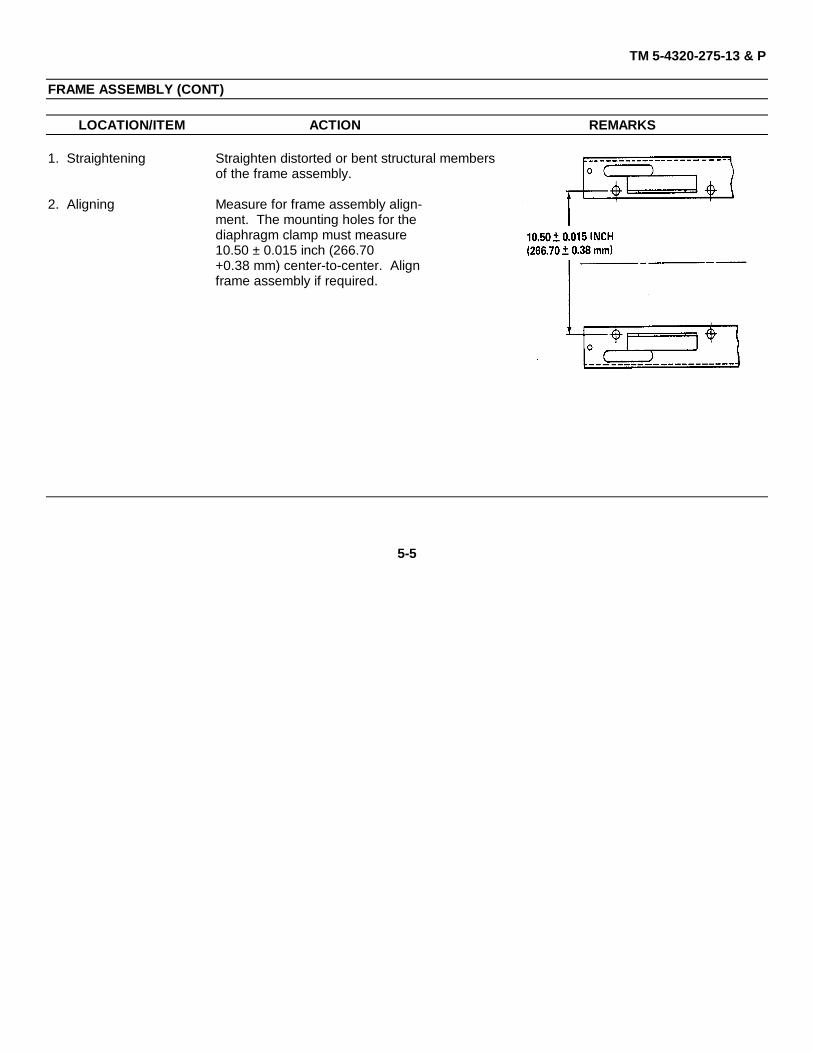
LOCATION/ITEM ACTION REMARKS
DISASSEMBLY
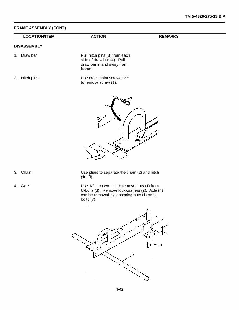
1. Draw bar Pull hitch pins (3) from eachside of draw bar (4). Pulldraw bar in and away fromframe.
2. Hitch pins Use cross point screwdriverto remove screw (1).
3. Chain Use pliers to separate the chain (2) and hitchpin (3).
4. Axle Use 1/2 inch wrench to remove nuts (1) fromU-bolts (3). Remove lockwashers (2). Axle (4)can be removed by loosening nuts (1) on U-bolts (3).
4-42
TM 5-4320-275-13 & P
FRAME ASSEMBLY (CONT)
LOCATION/ITEM ACTION REMARKS
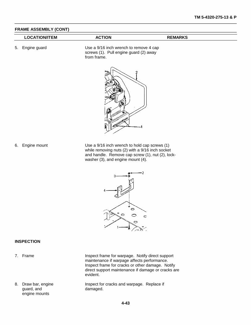
5. Engine guard Use a 9/16 inch wrench to remove 4 capscrews (1). Pull engine guard (2) awayfrom frame.
6. Engine mount Use a 9/16 inch wrench to hold cap screws (1)while removing nuts (2) with a 9/16 inch socketand handle. Remove cap screw (1), nut (2), lock-washer (3), and engine mount (4).
INSPECTION
7. Frame Inspect frame for warpage. Notify direct supportmaintenance if warpage affects performance.Inspect frame for cracks or other damage. Notifydirect support maintenance if damage or cracks areevident.
8. Draw bar, engine Inspect for cracks and warpage. Replace ifguard, and damaged.engine mounts
4-43
TM 5-4320-275-13 & P
FRAME ASSEMBLY (CONT)
LOCATION/ITEM ACTION REMARKS
9. Hitch pins Inspect hitch pins for cracks and spring tension.If pins are cracked or if they have no springtension, replace them.
10. Chains Inspect for cracked; or damaged links. Replacethe chain if cracked or if damage affects theconnecting of the chain to the hitch pin orscrew.
11. Axle Inspect for distortion or damage to the cotterpin holes. Notify direct support maintenance ifdistortion or damage is evident.
12. U-bolts Inspect for thread damage. Replace damagedU-bolts.
CLEANING
WARNINGClean parts in a well-ventilated area. Avoid inhalation of solvent fumes and prolongedexposure of skin to cleaning solvent. Wash exposed skin thoroughly. Dry cleaning solvent(fed spec P-D-680) used to. clean parts is potentially dangerous to personnel and property.Do not use near open flame or excessive heat. Flash point of solvent is 100° F (38° C).
13. Hitch pins, Immerse hitch pins and chains in cleaning solvent,chains, and P-D-680. After cleaning, wipe dry.U-bolts
14. Frame, axle, Clean frame and axle with dry cleaning solvent,draw bar, P-D-680. Use a stiff-bristle brush to remove cakedengine guard, dirt.and enginemounts
4-44
TM 5-4320-275-13 & P
FRAME ASSEMBLY (CONT)
LOCATION/ITEM ACTION REMARKS
ASSEMBLY
15. Axle Set axle (4) against frame and hold in placewith U-bolts (3). Install lockwashers (2) andnuts (1). Use Loctite onthreads.
16. Align axle Slide axle (4) in U-bolts (3) untileach end of the axle is equaldis-tance from the frame.
17. Nuts Use 1/2 inchwrench to tightennuts (1)to 4 ft lb (5 N•m).
NOTEDo not tighten U-bolts against axle.
18. Chains Install hitch pin (3) on chain(2).
19. Screws Insert screw (1) through thelast link in chain (2). Usecross point screwdriver toinstall screw (1) into frame.Use Loctite on threads.
20. Draw bar Insert draw bar (4) endsinto frame. Install hitchpins (3) into each end ofdraw bar.
4-45
TM 5-4320-275-13 & P
FRAME ASSEMBLY (CONT)
LOCATION/ITEM ACTION REMARKS
21. Engine guard Install cap screws (1) and use a 9/16 inch socketwith a torque wrench to tighten cap screws (1)to 30 ft lb (40 N.m). Coat threads with Loctiteand install cap screws (1).
22. Engine mount Use a 9/16 inch wrench to hold cap screws(1). Install lockwashers (3) and nuts (2). Usea 9/16 inch socket with a torque wrench totighten nuts (2) to 30 ft lb (40 N.m).
NOTEWhen engine mounts (4) are replaced, the engine must be alignedwith the coupling halves. The proper alignment is when bothcoupling halves slide together freely.
4-46
TM 5-4320-275-13 & P
4-17. WHEEL ASSEMBLY
This task covers:a. Removal b. Disassembly c. Inspectionc. Cleaning e. Assembly g. Installation
INITIAL SETUP
Test Equipment ReferencesNone None
ToolsTroubleshooting References
Tool kit, general mechanics automotive, NoneNSN 5180-00-177-7033
Tire ironPliers, long, round nose Special Environmental Conditions
Well-ventilated area required whenMaterials/Parts solvent is used.
1. Cotter pin Use pliers to remove cotterpin. Discard cotter pin.
2. Wheel assembly Remove flat washer to remove each wheelassembly.
DISASSEMBLY
3. Tire and tube Use tire iron or other tool to pry the sealingsurface of the deflated tire out over the hubassembly (2). Remove tire and tube (1).
4-48
TM 5-4320-275-13 & P
WHEEL ASSEMBLY (CONT)
LOCATION/ITEM ACTION REMARKS
INSPECTION
4. Tire Inspect tires for cuts, punctures, worn threads,imbedded stones, and severe abrasions. Inspectinside of tires for broken cords and puncturedwalls. Replace tires which are damaged beyondrepair or excessively worn.
5. Tube Check inner tube for leaks by inflating and im-mersing it in water. Any sign of bubbles indicatesa leak. Patch leaks. Check the tube for dry rotand other signs of deterioration. Replace non-serviceable tubes.
6. Hub assembly Inspect the hub assembly for cracks, distortion,burrs on the sealing rim, and other damage. Re-move all burrs with file or fine stone. Replacedamaged hub assemblies. Inspect bearings forrough, scored, or brinelled rollers, scored races,and bent cages. Replace hub assembly if bearingis damaged.
CLEANING
WARNING
Clean parts in a well-ventilated area. Avoid inhalation of solvent fumes and prolongedexposure of skin to cleaning solvent. Wash exposed skin thoroughly. Dry cleaning solvent(fed spec P-D-680) used to clean parts is potentially dangerous to personnel and property. Donot use near open flame or excessive heat. Flash point of solvent is 100° F (38° C).
7. Hub assemblies Clean hub assemblies with cleaning solvent,P-D-680, and dry thoroughly.
4-49
TM 5-4320-275-13 & P
WHEEL ASSEMBLY (CONT)
LOCATION/ITEM ACTION REMARKS
ASSEMBLY
8. Tire and tube Install tire on hub assembly and install inner tube.Be certain valve stem extends in the right directionand through hole in hub (5). Use tire iron to pryouter surface of tire over the hub rim. Inflate to30 psi (207 kPa).
INSTALLATION
9. Wheel assembly Install wheel assembly andflat washer on axle.
10. Cotter pin Insert a new cotter pin through hole in axle. Usepliers to bend one leg of the cotter pin along thecontour of the axle.
11. Grease fittings Lubricate wheels in accordance with lubricationorder LO 5-4320-275-12.
4-50
TM 5-4320-275-13 & P
4-18. DATA PLATES
This task covers:a. Inspection b. Cleaning c. Removald. Replacement
INITIAL SETUP
LOCATION/ITEM ACTION REMARKS
Test Equipment ReferencesNone None
Tools Troubleshooting ReferencesShop equipment, automotive Nonemaintenance and repair,NSN 4910-00-754-0654
Rivet kit Special Environmental ConditionsHammer, hand Well-ventilated area required whenAlpha-numeric die set solvent is used.Drill, electricDrill, twist, 1/8 inch General Safety Instructions
1. Data plates Inspect for legibility. If illegible, replace dataplate.
CLEANING
WARNINGClean parts in a well-ventilated area. Avoid inhalation of solvent fumes and prolongedexposure of skin to cleaning solvent. Wash exposed skin thoroughly. Dry cleaning solvent(fed spec P-D-680) used to clean parts is potentially dangerous to personnel and property. Donot use near open flame or excessive heat. Flash point of solvent is 100° F (38°C).
2. Data plates Wipe data plates with a soft cloth moistened withdry cleaning solvent, P-D-680. Wipe dry.
REMOVAL
3. Date plates Use an electric drill with a 1/8 inch twist drill toremove rivets holding data plate.
REPLACEMENT
4. Identification Use blank serial plate for replacement of the iden-plate tification plate. Use hammer and die set to stamp
serial plate with information applicable to eachidentification plate for each pump assembly.
NOTEWhere information on the identification plate is illegible, leave the block blank on the serialplate.
5. Data plates Use a rivet kit to install data plates on couplingguard.
4-52
TM 5-4320-275-13 & P
4-19. ACCUMULATOR
This task covers:a. Removal b. Inspection c. Cleaning.d. Assembly e. Installation
INITIAL SETUP
Test Equipment Personnel Required: 2None Mechanic will assist in lifting
accumulator.Tools
Shop equipment, automotivemaintenance and repair, ReferencesNSN 4910-00-754-0654 None
Socket, 3/4 inch, and handleWrench, 1-1/4 inchWrench, pipe, adj jaw style, 4 inch ips Troubleshooting ReferencesTorque wrench, 0-175 ft lb (0-250 N•m) Malfunction 3, step 2
1. Pipe plug Use 1-1/4 inch wrench to remove pipe plug (1)from accumulator.
2. Nipple Use pipe wrench to remove nipple (2).
3. Cap screws Use 3/4 inch socket and handle to remove fourcap screws (3) holding accumulator (8) on pumpbowl. Remove cap screws (3) and lockwashers (4).
4. Accumulator Remove accumulator (8).
NOTEGasket (5), seal plate (6), and check valve assembly (7) may stick to accumulator.
Remove and discard gasket (5). Remove seal plate(6), and check valve assembly (7) from accumulator.
4-54
TM 5-4320-275-13 & P
ACCUMULATOR (CONT)
LOCATION/ITEM ACTION REMARKS
INSPECTION
5. Accumulator Inspect accumulator for thread damage and warp-age. Replace if damaged or warped.
6. Pipe plug Inspect for damaged threads. Replace ifdamaged.
7. Nipple Inspect for damaged threads and cracks. Replaceif damaged or cracked.
8. Seal plate and Inspect for cracks and warpage. Replace ifcheck valve damaged or warped.assembly
CLEANING
WARNINGClean parts in a well-ventilated area. Avoid inhalation of solvent fumes and prolongedexposure of skin to cleaning solvent. Wash exposed skin thoroughly. Dry cleaning solvent(fed spec P-D-680) used to clean parts is potentially dangerous to personnel and property. Donot use near open flame or excessive heat. Flash point of solvent is 100° F (38°C).
9. Accumulator, Clean accumulator with cleaning solvent,nipple, seal P-D-680. Use a stiff-bristle brush to removeplate, and check caked dirt.valve assembly
10. Pipe plug Clean pipe plug with cleaning solvent,P-D-680.
INSTALLATION
11. Accumulator Place four cap screws (3) with lockwashers (4)through screw holes in accumulator (8). Installgasket (5) and seal plate (6) on cap screws (3).Install check valve assembly (7) on cap screws(3). Use Loctite on screw threads.
4-55
TM 5-4320-275-13 & P
ACCUMULATOR (CONT)
12. Cap screws Align cap screws with accumulator, gasket, andcheck valve assembly to threaded screw holes inpump bowl. Use 3/4 inch socket with a torquewrench to tighten the four cap screws to a torqueof 40 ft lb (54 N•m).
13. Nipple Use Loctite on nipple threads. Use pipe wrench toinstall nipple (2).
14. Pipe plug Use Loctite on pipe plug threads. Use 1-1/4 inchwrench to install pipe plug (1).
4-56
TM 5-4320-275-13 & P
4-20. DISCHARGE PORT
This task covers:a. Removal b. Inspection c. Cleaning.d. Installation
INITIAL SETUP
Test Equipment Check valve assembly (Appendix C,None item 8, fig.6)
Discharge port (Appendix C, item 9, fig.6)Tools Cleaning solvent, P-D-680
NoneSocket, 3/4 inch, and handleWrench, pipe, adj jaw style, 4 inch ips Troubleshooting ReferencesTorque wrench 0-175 ft lb (0-250 N•m) None
Materials/Parts Special Environmental ConditionsNipple (Appendix C, item 2, fig.6)Gasket (Appendix C, item 6, fig.6) Well-ventilated area required whenSeal plate (Appendix C, item 7, fig.6) solvent is used.
General Safety InstructionsNone
4-57
TM 5-4320-275-13 & P
DISCHARGE PORT (CONT)
REMOVAL
1. Nipple Use pipe wrench to remove nipple (1) from dis-charge port (4).
2. Screws Use 3/4 inch socket and handle to remove fourcap screws (2) holding discharge port (4) onpump bowl. Remove cap screws (2) and lock-washers (3).
3. Discharge port Remove discharge port (4).
NOTEGasket (6), seal plate (7), and check valve assembly (5) may stick to the discharge port.
Remove and discard gasket (6). Remove seal plate(7), and check valve assembly (5) from discharge port.
INSPECTION
4. Discharge port Inspect discharge port for thread damage and warp-age. Replace if damaged or warped.
5. Seal plate and Inspect for cracks or warpage. Replace if damaged.check valveassembly
6. Nipple Inspect for damaged threads and cracks. Replaceif damaged or cracked.
4-58
TM 5-4320-275-13 & P
DISCHARGE PORT (CONT)
LOCATION/ITEM ACTION REMARKS
CLEANING
WARNINGClean parts in a well-ventilated area. Avoid inhalation of solvent fumes and prolongedexposure of skin to cleaning solvent. Wash exposed skin thoroughly. Dry cleaning solvent(fed spec P-D-680) used to clean parts is potentially dangerous to personnel and property. Donot use near open flame or excessive heat. Flash point of solvent is 100°F (38°C).
7. Discharge port, Clean with cleaning solvent, P-D-680. Use a stiff-nipple, seal bristle brush to remove caked dirt.plate, and checkvalve assembly
INSTALLATION
8. Discharge port Place four cap screws (2) with lockwashers (3)through screw holes in discharge port (4). Installcheck valve assembly (5), seal plate (7), andgasket (6) on cap screws (2). Use Loctite onscrew threads.
9. Cap screws Align cap screws with discharge port, gasket,seal plate, and check valve assembly to threadedscrew holes in pump bowl. Use 3/4 inch socketwith torque wrench to tighten the four capscrews to a torque of 40 ft lb (54 N•m).
10. Nipple Use Loctite on nipple threads. Use pipe wrenchto install nipple (1).
4-59
TM 5-4320-275-13 & P
4-21. DIAPHRAGM
This task covers:a. Removal b. Inspection c. Cleaning.d. Installation
INITIAL SETUP
Test Equipment Personnel Required: 2None Mechanic will assist in lifting pump assembly.
ReferencesTools None
Shop equipment, automotivemaintenance and repair, Troubleshooting ReferencesNSN 4910-00-754-0654 None
Socket, 15/16 inch, and handle Equipment ConditionSocket, 3/4 inch, and handle Drain plug removed from pump bowl toTorque wrench, 0-175 ft lb (0-250 N.m) remove fluid from pump
.
Materials/Parts Special Environmental ConditionsWell-ventilated area required when
Diaphragm (Appendix C, item 6, fig. 7) solvent is used.Loctite (Item 7, Appendix D)Cleaning solvent, P-D-680 General Safety Instructions
None
4-60
TM 5-4320-275-13 & P
DIAPHRAGM (CONT)
LOCATION/ITEM ACTION REMARKS
REMOVAL
1. Pump bowl Use 15/16 inch socket and handle to remove fourassembly cap screws (1) and lockwashers (2) holding pump
bowl assembly (3) to diaphragm clamp (8).
4-61
TM 5-4320-275-13 & P
DIAPHRAGM (CONT)
LOCATION/ITEM ACTION REMARKS
NOTEUse draw bar to lift pump assembly up and away from pump bowl assembly (3). The pumpassembly will pivot on its wheels to aid in lifting.
2. Nuts To break seal, pull diaphragm (6) away from lipof diaphragm clamp (8). Use 3/4 inch socketand handle to loosen four nuts (4). Remove nuts(4) and lockwashers (5).
3. Diaphragm Pull clamp assembly (7) away from connectingrod. Separate diaphragm (6) from clamp assem-bly (7).
INSPECTION
4. Diaphragm Inspect diaphragm for cracks or tears. Replacedamaged diaphragm.
CLEANING
WARNINGClean parts in a well-ventilated area. Avoid inhalation of solvent fumes and prolongedexposure of skin to cleaning solvent. Wash exposed skin thoroughly. Dry cleaning solvent(fed spec P-D-680) used to clean parts is potentially dangerous to personnel and property. Donot use near open flame or excessive heat. Flash point of solvent is 100°F (38°C).
5. Diaphragm Clean the diaphragm with cleaning solvent,P-D-680. Wipe dry.
4-62
TM 5-4320-275-13 & P
DIAPHRAGM (CONT)
LOCATION/ITEM ACTION REMARKS
INSTALLATION
6. Diaphragm Install diaphragm (6) over studs on clamp assem-bly (7).
4-63
TM 5-4320-275-13 & P
DIAPHRAGM (CONT)
LOCATION/ITEM ACTION REMARKS
7. Clamp assembly Install clamp assembly (7) with diaphragm (6) onconnecting rod.
8. Nuts Use Loctite on threads of studs. Install lock-washers (5) and nuts (4). Use 3/4 inch socketwith a torque wrench to tighten nuts (4) to40 ft lb (54 N•m).
9. Pump bowl Use the draw bar to lift pump assembly overassembly pump bowl assembly (3).
NOTE
The pump assembly will pivot on its wheels to aid in lifting.
CAUTION
Be certain diaphragm is seated on pump bowl assembly seat. Align screw holes of pumpbowl assembly (3) with threaded holes in diaphragm clamp (8). Install cap screws (1) andlockwashers (2). Use Loctite on screw threads.
10. Cap screws Use 15/16 inch socket with torque wrench totighten cap screws (1) to 75 ft lb (102 N•m).
4-64
TM 5-4320-275-13 & P
4-22. CLAMP ASSEMBLY
This task covers:a. Disassembly
b. Inspection
c. Cleaning
d. Assembly
INITIAL SETUP
Test Equipment References
None None
Tools Troubleshooting References
Shop equipment, automotive Nonemaintenance and repair,NSN 4910-00-754-0654
Equipment ConditionStud removing and installing tool, 1/2 inch
Pump bowl assembly and diaphragm removedMaterials/Parts for access to clamp assembly.
Stud (Appendix C, item 8, fig. 7) Special Environmental Conditions
Connecting rod clamp (Appendix C, Well-ventilated area required whenitem 9, fig. 7) solvent is used.
1. Studs Use 1/2 inch stud removing and installingtool to remove studs (1): from con-necting rod clamp (2).
INSPECTION
2. Threads Inspect threads on studs. (1) and threads in con-necting rod clamp (2) for damage. Replacedamaged parts.
3. Connecting Inspect connecting rod clamp (2) for cracks orrod clamp warpage. Replace if damaged.
CLEANING
WARNING
Clean parts in a well-ventilated area. Avoid inhalation of solvent fumes and prolongedexposure. of skin to cleaning solvent. Wash exposed skin thoroughly. Dry cleaning solvent(fed spec P-D,680) used to clean parts is potentially dangerous to personnel and property. Donot use near open flame or excessive heat. Flash point of solvent is 100°F (38°C).
4. Studs and Clean studs and connecting rod clamp withconnecting cleaning solvent, P-D-680. Use a stiff-bristlerod clamp brush to remove caked dirt.
4-66
TM 5-4320-275-13 & P
CLAMP ASSEMBLY (CONT)
LOCATION/ITEM ACTION REMARKS
ASSEMBLY
5. Studs Use Loctite on stud threads. Use 1/2 inch studremoving and installing tool to install studs (1)into connecting rod clamp (2). Tighten studsuntil they are flush with bottom of connectingrod clamp.
4-67
TM 5-4320-275-13 & P
4-23. PUMP BOWL
This task covers:a. Removal of pump bowl from diaphragm clamp.
b. Disassembly
c. Inspection
d. Cleaning
e. Assembly
f. Installation of pump bowl on diaphragm clamp.
INITIAL SETUP
Test Equipment Personnel Required: 2
None Mechanic will assist in lifting pump assemblyand pump bowl.
Tools References
Shop equipment, automotive Nonemaintenance and repair,NSN 4910-00-754-0654 Troubleshooting References
Socket, 15/16 inch, and handle None
Wrench, 5/8 inch Equipment Condition
Torque wrench, 0-175 ft lb (0-250 N• m) Accumulator, discharge port, gaskets, sealplates, and valve assemblies removed foraccess to pump bowl.
Materials/PartsSpecial Environmental Conditions
Drain plug (Appendix C, item 3, fig. 7)Well-ventilated area required when
Loctite (Item 7, Appendix D) General Safety Instructions
Cleaning solvent, P-D-680 None
4-68
TM 5-4320-275-13 & P
PUMP BOWL (CONT)
LOCATION/ITEM ACTION REMARKS
REMOVAL
1. Pump bowl Use 15/16 inch socket andhandle to remove four capscrews (1) and lockwashers(2) holding pump bowl (3)to diaphragm clamp (5).
NOTEUse the draw bar to lift pump assembly up and away from pump bowl. The pump assemblywill pivot on its wheels to aid in lifting.
4-69
TM 5-4320-275-13 & P
PUMP BOWL (CONT)
LOCATION/ITEM ACTION REMARKS
DISASSEMBLY
2. Drain plug Use 5/8 inch wrench to remove drain plug (4)from pump bowl (3).
INSPECTION
3. Pump bowl Inspect for cracks, warpage, and damagedthreads. Replace pump bowl if damaged.
4. Drain plug Inspect for thread damage. Replace drain plugif threads are damaged.
CLEANING
WARNINGClean parts in a well-ventilated area. Avoid inhalation of solvent fumes and prolongedexposure of skin to cleaning solvent. Wash exposed skin thoroughly. Dry cleaning solvent(fed spec P-D-680) used to clean parts is potentially dangerous to personnel and property. Donot use near open flame or excessive heat. Flash point of solvent is 100°F (38°C).
5. Pump bowl Clean pump bowl and drain plug with cleaning sol-and drain plug vent, P-D-680. Use a stiff-bristle brush to remove
caked dirt.
4-70
TM 5-4320-275-13 & P
PUMP BOWL (CONT)
LOCATION/ITEM ACTION REMARKS
ASSEMBLY
6. Drain plug Use Loctite on drain plug threads. Use 5/8 inchwrench to install drain plug (4) on pump bowl(3). Tighten until plug is snug.
4-71
TM 5-4320-275-13 & P
PUMP BOWL (CONT)
LOCATION/ITEM ACTION REMARKS
INSTALLATION
7. Pump bowl Use the draw bar to lift pump assembly overpump bowl (3).
NOTE
The pump, assembly will pivot on its wheels to aid in lifting.
Align screw holes of pump bowl (3) withthreaded holes in diaphragm clamp (5). UseLoctite on threads. Install cap screws (1)and lockwashers (2).
8. Cap screws Use 15/16 inch socket with a torque wrench totighten cap screws (1) to 75 ft lb (102 N•m).
4-72
TM 5-4320-275-13 & P
4-24. CONNECTING ROD ASSEMBLY
This task covers:a. Removal
b. Disassembly
c. Inspection
d. Cleaning
e. Assembly
f. Installation
INITIAL SETUP
Test Equipment Materials/Parts
None Shoulder bolt (Appendix C, item 3, fig. 8)
Connecting rod assembly (Appendix C,item 4, fig. 8)
Socket, 1-1/8 inch and handle Troubleshooting References
NoneSocket, 3/4 inch and handle
Special Environmental ConditionsWrench, 15/16 inch, or
Well-ventilated area required whenSocket, 15/16 inch and handle solvent is used.
Torque wrench, 0-175 ft lb General Safety Instructions(0-250 N•m) None
4-73
TM 5-4320-275-13 & P
CONNECTING ROD ASSEMBLY (CONT)
LOCATION/ITEM ACTION REMARKS
REMOVAL
NOTEPosition connecting rod to the down position.
1. Nuts Use 3/4 inch socket and handle to remove nuts(1). Remove lockwashers (2).
2. Connecting rod Use 1-1/8 inch socket and handle to removeassembly shoulder bolt (4). Hand crank the engine until
connecting rod (3) is clear of the studs protrud-ing through the diaphragm. Slide the connectingrod assembly off crank (6).
3. Crank Use 15/16 inch socket and handle to remove capscrew (7). Remove lockwasher (8). Slide crank(6) off gear reducer shaft. Remove squarekey (9).
4-74
TM 5-4320-275-13 & P
CONNECTING ROD ASSEMBLY (CONT)
LOCATION/ITEM ACTION REMARKS
DISASSEMBLY
4. Grease fitting Use 9/16 inch wrench to remove grease fitting(5).
INSPECTION
5. Shoulder bolt Inspect for damaged threads. Replace ifdamaged.
6. Connecting rod Inspect for cracks, damaged threads in greasefitting hole, galled bearing bore, and warpage.Replace if any damaged is evident.
7. Crank Inspect for cracks, damaged threads in greasefitting hole, damaged bearing, and warpage.Replace if any damage is evident.
CLEANING
WARNING
Clean parts in a well-ventilated area. Avoid inhalation of solvent fumes and prolongedexposure of skin to cleaning solvent. Wash exposed skin thoroughly. Dry cleaning solvent(fed spec P-D-680) used to clean parts is potentially dangerous to personnel and property. Donot use near open flame or excessive heat. Flash point of solvent is 100° F (38° C).
9. Connecting rod Clean with dry cleaning solvent, P-D-680. Use astiff-bristle brush to remove caked dirt. Use a soft-bristle brush to remove old grease from bearing.Wipe dry. Coat the bearing with light oil.
4-75
TM 5-4320-275-13 & P
CONNECTING ROD ASSEMBLY (CONT)
LOCATION/ITEM ACTION REMARKS
10. Crank Wash in dry cleaning solvent, P-D-680. Use a soft-bristle brush to remove old grease. After cleaning,wipe the bore and journal surfaces with light oiland wrap in lint-free paper until ready to assembleon speed reducer and connecting rod.
11. Grease fitting Use 9/16 inch wrench to install grease fitting (5).
INSTALLATION
12. Crank Install square key (9) into keyway in gear reducershaft. Align keyway of crank (6) with square key(9). Slide crank over square key and onto gearreducer shaft.
4-76
TM 5-4320-275-13 & P
CONNECTING ROD ASSEMBLY (CONT)
LOCATION/ITEM ACTION REMARKS
13. Cap screw Use Loctite on cap screw threads. Install lock-and lockwasher washer (8) and cap screw (7) on crank. Do not
tighten until connecting rod assembly has beeninstalled.
14. Connecting Hand crank engine until square key is rotated torod assembly the 12 o-clock position. Install connecting rod
assembly on the crank.
15. Shoulder bolt Use Loctite on shoulder bolt threads. Installshoulder bolt (4) through connecting rod (3)and into crank (6). Use 1-1/8 inch socket withtorque wrench to tighten shoulder bolt (4) to75 ft lb (102 N•m).
16. Nuts Align four holes in connecting rod (3) withstuds sticking through diaphragm.
NOTEHand crank the engine to lower the connecting rod to the studs.
Use Loctite on stud threads. Install lockwashers(2) and nuts (1). Use 3/4 inch socket with torquewrench to tighten nuts (1) to 40 ft lb (54 N•m).
17. Tighten cap Use 15/16 inch socket with torque wrench toscrew tighten cap screw (7) to 75 ft lb (102 N•m).
4-77
TM 5-4320-275-13 & P
4-25. COUPLING
This task covers:a. Removal
b. Inspection
c. Cleaning
d. Installation
INITIAL SETUP
Test Equipment References
None None
Tools Troubleshooting References
Tool kit, general mechanics automotive, NoneNSN 5180-00-177-7033
Key, hex drive, 5/32 inch Equipment Condition
Materials/Parts Engine and coupling guard removed foraccess to coupling.
Spider (Appendix C, item 19, fig. 8)Well-ventilated area required when
Key (Appendix C, item 20, fig. 8) solvent is used.
Key (Appendix C, item 21, fig. 8) General Safety Instructions
Cleaning solvent, P-D-680 None
4-78
TM 5-4320-275-13 & P
COUPLING (CONT)
LOCATION/ITEM ACTION REMARKS
REMOVAL
1. Setscrew Use a 5/32 inch hex key to loosen one setscrewin each coupling half.
2. Coupling Pull coupling half (1) from engine shaft. Removehalves and discard key (4). Pull coupling half (2) from
gear reducer shaft. Remove key (5) from gearreducer shaft.
3. Spider Separate spider (3) from coupling half.
INSPECTION
4. Coupling Inspect coupling halves for cracks in metal. Re-halves place coupling if damaged.
5. Spider Inspect for cracks or tears in rubber spider. Re-place spider if damaged.
4-79
TM 5-4320-275-13 & P
COUPLING (CONT)
LOCATION/ITEM ACTION REMARKS
CLEANING
WARNING
Clean parts in a well-ventilated area. Avoid inhalation of solvent fumes and prolongedexposure of skin to cleaning solvent. Wash exposed skin thoroughly. Dry cleaning solvent(fed spec P-D-680) used to clean parts is potentially dangerous to personnel and property. Donot use near open flame or excessive heat. Flash point of solvent is 100° F (38° C).
6. Coupling Clean with dry cleaning solvent, P-D-680. Wipehalves and dry.spider
INSTALLATION
7. Coupling Install a new key (4) on engine shaft. Slidehalves coupling half (1) on engine shaft and tighten
setscrew with a 5/32 inch hex key.
Install key (5) on gear reducer shaft. Slidecoupling half (2) on gear reducer shaft andtighten setscrew with a 5/32 inch hex key.
8. Spider Install spider on gear reducer coupling half.
4-80
TM 5-4320-275-13 & P
4-26. GEAR REDUCER
This task covers:a. Removal
b. Inspection
d. Installation
INITIAL SETUP
Test Equipment References
None None
Tools Troubleshooting References
Shop equipment, automotive Nonemaintenance and repair,NSN 4910-00-754-0654
Equipment Condition
Wrench, 15/16 inch Engine, coupling guard, and couplingremoved for access to gear reducer.
Socket, 15/16 inch and handle
Torque wrench, 0-175 ft lb (0-250 N•m) Special Environmental Conditions
1. Cap screw Use 15/16 inch socket andon crank handle to loosen cap screw
(7). Do not remove screwfrom crank.
2. Cap screws Use 15/16 inch socket and handle to remove capclosest to screws (4). Remove two cap screws (4) and lock-crank washers (5).
3. Cap screws Use 15/16 inch wrench to hold nuts (2). Useand nuts 15/16 inch socket and handle to remove cap
screws (1). Remove two cap screws (1), nuts(2), and lockwashers (3).
4. Gear reducer Slide gear reducer (6) away from crank.
NOTEIt may be necessary to open crank to release gear reducer shaft.
INSPECTION
5. Shaft Check for input and output shaft rotation. Ifeither shaft binds or does not rotate, replacegear reducer.
4-82
TM 5-4320-275-13 & P
GEAR REDUCER (CONT)
LOCATION/ITEM ACTION REMARKS
INSTALLATION
6. Gear reducer Set gear reducer (6) onframe. Slide gear reducershaft into crank. Alignfour screw holes in gearreducer and frame.
7. Cap screws Use Loctite on screw threads. Use 15/16 inchand nuts wrench to hold nuts (2). Use 15/16 inch socket
and handle to install two cap screws (1). Installnuts (2) and lockwashers (3).
NOTEDo not tighten.
8. Cap screws Use Loctite on screw threads. Use 15/16 inchclosest to socket and handle to install two cap screws (4).crank Install lockwashers (5).
NOTEDo not tighten.
9. Tighten cap Use 15/16 inch socket with a torque wrench toscrews tighten cap screws (1, 4, and 7) to a torque of
75 ft lb (102 N•m).
4-83
TM 5-4320-275-13 & P
Section VII. PREPARATION FOR STORAGE OR SHIPMENT
4-27. GENERAL
This section provides instructions for preparation of the pump assembly for storage or shipment.
4-28. ADMINISTRATIVE STORAGE
a. Placement of equipment in administrative storage should be for short periods of time when a shortage ofmaintenance effort exists. Items should be in mission readiness within 24 hours or within the time factors as determinedby the directing authority. During the storage period appropriate maintenance records will be kept.
b. Before placing equipment in administrative storage, current maintenance services and equipment serviceablecriteria (ESC) evaluations should be completed, shortcomings and deficiencies should be corrected, and all modificationwork orders (MWO's) should be applied.
c. Storage site selection. Inside storage is preferred for items selected for administrative storage. If inside storageis not available, trucks, vans, conex containers and other containers may be used.
4-29. PACKING AND SHIPPING
a. Use shipping plugs, closures, or sealing tape to cover all openings in the pump assembly.
b. Attach to the pump assembly all forms, tags, and records applicable to the unit.
Change 3 4-84
TM 5-4320-275-13 & P
CHAPTER 5
DIRECT SUPPORT MAINTENANCE INSTRUCTIONS
This chapter contains the following frequently used maintenance information:
a. Information on repair parts, special tools, TMDE, and support equipment.
b. Troubleshooting
c. Maintenance procedures
The Symptom Index on page 5-2 is a guide to the troubleshooting information. There is also an index to themaintenance procedures on page 5-3.
Section Title Page
I Repair Parts, Special Tools, TMDE, and Support Equipment ........................................................5-1II Troubleshooting . ..........................................................................................................................5-2
III Maintenance Procedures...............................................................................................................5-3
Section I. REPAIR PARTS, SPECIAL TOOLS, TMDE, AND SUPPORT EQUIPMENT
5-1. COMMON TOOLS AND EQUIPMENT
For authorized common tools and equipment, refer to the Modified Table of Organization and Equipment (MTOE)applicable to your unit.
5-2. SPECIAL TOOLS, TMDE, AND SUPPORT EQUIPMENT
No special tools, TMDE, or support equipment is required for this pump.
5-3. SPARES AND REPAIR PARTS
Spares and repair parts are listed and illustrated in Appendix C of this manual.
5-1
TM 5-4320-275-13 & P
Section II. TROUBLESHOOTING
5-4. TROUBLESHOOTING
a. Table 5-1 contains troubleshooting information for locating and correcting most of the operating troubles whichare the responsibility of direct support maintenance. Each malfunction for an individual component, unit, or system isfollowed by a list of tests or inspections which will help you to determine probable causes and corrective actions to take.Perform the tests/inspections and corrective actions in the order listed.
b. This manual cannot list all malfunctions that may occur, nor all tests or inspections and corrective actions. If amalfunction is not listed or is not corrected by listed corrective actions, notify your supervisor.
c. Only those functions within the scope of direct support maintenance are listed. For troubleshooting procedureswithin the scope of operator/crew maintenance, refer to table 3-1. For troubleshooting procedures within the scope oforganizational maintenance, refer to table 4-3.
5-5. SYMPTOM INDEX
Refer to the Symptom Index below. Locate the malfunction which is the same, or most nearly the same, as the troubleyou are having with the pump assembly. The Symptom Index lists the first page of troubleshooting information for thatmalfunction. Follow the steps one by one, and perform the corrective actions listed.
MalfunctionNumber Description Page
1 Gear reducer input shaft will not rotate. 5-22 Gear reducer output shaft will not rotate. 5-2
Table 5-1. Direct Support Troubleshooting
MALFUNCTIONTEST OR INSPECTION
CORRECTIVE ACTION
1. GEAR REDUCER INPUT SHAFT WILL NOT ROTATE.
Step 1. Check for broken gear or bearing.
Disassemble gear reducer and replace broken parts in accordance withparagraph 5-11.
2. GEAR REDUCER OUTPUT SHAFT WILL NOT ROTATE.
Step 1. Check for broken gear or bearing.
Disassemble gear reducer and replace broken parts in accordance withparagraph 5-11.
5-2
TM 5-4320-275-13 & P
Section III. MAINTENANCE PROCEDURES
INDEXPara Para
Accumulator 5-9 Gear Reducer 5-11Crank and Connecting Rod 5-10 General Instructions 5-6Discharge Port 5-9 Pump 5-8Frame Assembly 5-7
5-6. GENERAL INSTRUCTIONS
Most maintenance instructions in this section will list resources required, personnel required, and equip-ment condition for the start of the procedure. Note the following:
• Resources required are not listed unless they apply to the procedure.
• Personnel required are listed only if the task requires more than one. If PERSONNEL is not listed, it means oneperson can do the task.
• The normal standard equipment condition to start a maintenance task is engine stopped and cutoff switch off.EQUIPMENT CONDITION is not listed unless some other condition is required besides the power being off.
5-3
TM 5-4320-275-13 & P
5-7. FRAME ASSEMBLYThis task covers:
a. Straightening bent frame.
b. Aligning frame.
INITIAL SETUPTest equipment
None
ToolsShop equipment, automotivemaintenance and repairNSN 4910-00-754-0654
Equipment ConditionEngine, engine guard, coupling guard, gearreducer, pump assembly, wheels, and axleremoved for access to frame assembly.
Special Environmental ConditionsNone
General Safety instructionsNone
5-4
TM 5-4320-275-13 & P
FRAME ASSEMBLY (CONT)
LOCATION/ITEM ACTION REMARKS
1. Straightening Straighten distorted or bent structural membersof the frame assembly.
2. Aligning Measure for frame assembly align-ment. The mounting holes for thediaphragm clamp must measure10.50 ± 0.015 inch (266.70+0.38 mm) center-to-center. Alignframe assembly if required.
5-5
TM 5-4320-275-13 & P5-8. PUMP
This task covers:
Thread repair.
INITIAL SETUPTest equipment
None
Tools
Shop equipment, automotivemaintenance and repairNSN 4910-00-754-0654
Tap, 1/2-13 UNC-2B, and handleTap, 5/8-11 UNC-2B, and handleTap, 1/2 inch NPT, and handle
Personnel Required: 2Mechanic will assist in lifting accumulator.
ReferencesNone
Troubleshooting ReferencesNone
Equipment ConditionAccumulator and discharge portremoved from pump assembly.
Special Environmental ConditionsNone
General Safety instructionsCompressed air for cleaning shall not exceed30 psi (207 kPa). Use goggles or face shieldto prevent eye injury from flying chips.
5-8
TM 5-4320-275-13 & P
ACCUMULATOR AND DISCHARGE PORT (CONT)
LOCATION/ITEM ACTION REMARKS
1. Accumulator Use 2 inch NPT tap and handle to repairthreads in accumulator pipe plug hole. Blowout chips with compressed air.
Use 4 inch NPT tap and handle to repairthreads in accumulator pipe nipple hole.Blow out chips with compressed air.
2. Discharge port Use 4 inch NPT tap and handle to repairthreads in pipe nipple hole. Blow out chipswith compressed air.
5-9
TM 5-4320-275-13 & P
5-10. CRANK AND CONNECTING ROD
This task covers:
a. Bearing replacement.
b. Inner race replacement.
c. Thread repair.
INITIAL SETUP
Test equipment
None
Tools
Shop equipment, automotivemaintenance and repairNSN 4910-00-754-0654
Puller, mechanical, gear and bearing
Tap, 5/8-11 UNC-2B, and handle
Materials/Parts
Crank (Appendix C, item 12, fig. 8)
References
None
Troubleshooting References
None
Equipment Condition
Crank removed from drive.
Special Environmental Conditions
None
General Safety instructions
Compressed air for cleaning shall not exceed30 psi (207 kPa). Use goggles or face shieldto prevent eye injury from flying chips.
5-10
TM 5-4320-275-13 & P
CRANK AND CONNECTING ROD (CONT)
LOCATION/ITEM ACTION REMARKS
DISASSEMBLY
1. Bearing Remove roller bearing (2) from connecting rod (1).
2. Inner race Use a mechanical gear and bearing puller to re-move inner race (4) from crank (3).
5-11
TM 5-4320-275-13 & P
CRANK AND CONNECTING ROD (CONT)
LOCATION/ITEM ACTION REMARKS
REPAIR
3. Crank Use 5/8-11 UNC-2B tap and handle to repairthreads. Blow out-chips with compressed air.
5-12
TM 5-4320-275-13 & P
CRANK AND CONNECTING ROD (CONT)
LOCATION/ITEM ACTION REMARKS
ASSEMBLY
4. Bearing Use an arbor press to install bearing (2) intoconnecting rod (1).
5. Inner race Use an arbor press to install inner race (4) oncrank (3).
5-13
TM 5-4320-275-13 & P
5-11. GEAR REDUCER
This task covers:
a. Disassembly
b. Inspection
c. Cleaning
d. Assembly
INITIAL SETUP
Test equipment
None
Tools
Shop equipment, automotivemaintenance and repairNSN 4910-00-754-0654
Wrench, 7/16 inch
Wrench, 3/8 inch
Wrench, 9/16 inch, or
Socket, 9/16 inch, and handle
Screwdriver, 1/4 inch blade
Puller, mechanical, gearand bearing
Pliers, retaining ring
Pliers, hose clamp
Torque wrench, 0-175 ft lb (0-250 N•m)NSN 5120-00-640-6364
Well-ventilated area required whensolvent is used.
General Safety instructions
None
5-14
TM 5-4320-275-13 & P
GEAR REDUCER (CONT)
LOCATION/ITEM ACTION REMARKS
DISASSEMBLY
1. Drain oil Drain oil into drain pan. Use 3/8 inchwrench to remove drain plug (1). Use7/16 inch wrench to remove levelplug (2) and breather (3).
2. Output cover Use 9/16 inch socket and handle toremove eight cap screws (1). Removeoutput cover (2). Remove and dis-card output seal (3).
3. Output shaft Remove output shaft from gear reducer as anassembly. Use gear and bearing mechanical pullerto remove outboard bearing (1) and inboardbearing (2) from output shaft (6). Removespacer (3).
5-15
TM 5-4320-275-13 & P
GEAR REDUCER (CONT)
LOCATION/ITEM ACTION REMARKS
4. Gear Use gear and bearing mechanical puller to removegear (4) from output shaft (6). Remove key (5).
5. Input cover Use 9/16 inch socket and handle toremove eight cap screws (1). Re-move input cover (2). Remove anddiscard input seal (3).
6. Input shaft Use retaining ring pliers to remove snap ring (1)from input cover (2). Remove input shaft (5)with bearings (3 and 4) from input cover (2).
7. Bearings Use gear and bearing mechanical puller to re-move input cover bearing (3) and input bearing(4) from input shaft (5).
NOTEPinion and input shaft are a permanent assembly. Do not attempt to separate them.
5-16
TM 5-4320-275-13 & P
GEAR REDUCER (CONT)
LOCATION/ITEM ACTION REMARKS
8. Gear Use screwdriver to press tang of lockwasher (2)away from locknut (1). Use hose clamp pliers toremove locknut (1). Remove lockwasher (2). Usegear and bearing mechanical puller to removegear (3).
9. Jackshaft Remove key (6) from jackshaft (9). Removespacer and key jackshaft spacer (4).
10. Jackshaft Use retaining ring pliers to remove snap ring (5)from groove in reducer housing bore. Removejackshaft (9), bearing (7), and bearing (8) as anassembly.
11. Bearings Use gear and bearing mechanical puller to re-move bearings (7 and 8) from jackshaft (9).
INSPECTION
12. Covers Inspect input and output covers for cracks andwarpage. Replace if damaged.
13. Output shaft Inspect for damaged keyways and galled bearingjournals. Replace if damaged.
14. Input shaft Inspect for damaged keyways, galled bearingand jackshaft journals, and damaged gear teeth. Replace if
damaged.
5-17
TM 5-4320-275-13 & P
GEAR REDUCER (CONT)
LOCATION/ITEM ACTION REMARKS
15. Bearings Bearings must turn freely without binding. In-spect for brinelled or burnished areas. Replacedamaged bearing.
16. Gears Inspect for chipped-or eroded gear teeth. Anyevidence of gear tooth damage will require gearreplacement.
CLEANING
WARNING
Clean parts in a well-ventilated area. Avoid inhalation of solvent fumes and prolongedexposure of skin to cleaning solvent. Wash exposed skin thoroughly. Dry cleaning solvent(fed spec P-D-680) used to clean parts is potentially dangerous to personnel and property. Donot use near open flame or excessive heat. Flash point of solvent is 100° F (38° C).
17. Covers and Clean with cleaning solvent, P-D-680. Use a stiff-gear housing bristle brush to remove caked dirt. After cleaning
wipe all bearing bores with light oil.18. Bearings
CAUTION
Do not spin bearing when cleaning. Damage can result from spinning.
Soak the bearings in dry cleaning solvent, P-D-680,and use a soft-bristle brush to remove old grease.After cleaning, dip the bearing in light oil andwrap in lint-free paper until ready to assemble.
19. Input shaft, Wash in dry cleaning solvent, P-D-680. Use a soft-output shaft, bristle brush to remove old grease. After cleaning,jackshaft, wipe with light oil and wrap in lint-free paperand gears until ready to assemble.
5-18
TM 5-4320-275-13 & P
GEAR REDUCER (CONT)
LOCATION/ITEM ACTION REMARKS
ASSEMBLY
NOTEPrior to assembly, pack all bearings in grease, MIL-G-18709.
20. Bearings Using an arbor press, install bearings (7 and 8) onjackshaft (9).
21. Jackshaft Insert jackshaft (9) with bearings (7 and 8)through gear housing web from the input side.Press jackshaft (9) until bearing (7),is seatedpast the snap ring groove. Use retaining ringpliers to install snap ring (5).
22. Jackshaft Slide jackshaft spacer (4) over jackshaft andspacer and against bearing (7). Install key (6) into jackshaftkey keyway.
23. Gear on Align keyway in gear (3) with key (6), andjackshaft press gear on jackshaft (9). Slide keyed lock-
washer (2) on jackshaft. Apply Loctite No. 242on threads of locknut (1) and install locknut.When locknut is snug against lockwasher, aligna flat of the locknut with a tang of the lock-washer. Bend tang over locknut flat.
5-19
TM 5-4320-275-13 & P
GEAR REDUCER (CONT)
LOCATION/ITEM ACTION REMARKS
24. Bearings on Using an arbor press,input shaft install bearings (3 and
4) on input shaft (5).
25. Input shaft Insert input shaft (5) with bearings (3 and 4) intoand through input cover (2). Press input coverbearing (3) into input cover (2) until it is seatedpast snap ring groove. Use retaining ring pliers toinstall snap ring (1).
26. Input cover Coat mounting face of input cover(2) with sealer, Silmate No.A689005AA-006. Assemble inputcover (2) to gear housing.
NOTEEngage input shaft gear with jackshaft gear when installing input cover.
Apply Loctite No. 242 to threads of eight capscrews (1). Use 9/16 inch socket and torquewrench to tighten cap screws to 31 ft lb (42 N•m).Pack grease, MIL-G-18709, in input bearing cavityin input cover (2) and install new seal (3) flushwith input cover face.
5-20
TM 5-4320-275-13 & P
GEAR REDUCER (CONT)
LOCATION/ITEM ACTION REMARKS
27. Gear on Install key (5) into keyway of output shaft (6).output shaft Align keyway in gear (4) with key (5), and press
gear on output shaft (6) until it bottoms againstthe shaft shoulder.
28. Output shaft Install spacer (3) against gear (4). Press inboardbearing (2) on output shaft (6) and againstspacer (3). Press outboard bearing (1) on outputshaft until it bottoms against the output shaftshoulder.
29. Install output Install output shaft assembly into gear housingshaft until inboard bearing (2) bottoms on shoulder
of bearing bore.
NOTEEngage output shaft gear with jackshaft gear.
30. Output cover Coat output cover (2) mountingface with sealer, Silmate No.A689005AA-006. Assemble out-put cover to gear housing. ApplyLoctite No. 242 to threads ofeight cap screws (1).
5-21
TM 5-4320-275-13 & P
GEAR REDUCER (CONT)
LOCATION/ITEM ACTION REMARKS
CAUTIONAlign bearing bores with bearings being careful not to cock either bearing bore. Tighten capscrews evenly and with equal torque.
Use 9/16 inch socket and torque wrench totighten cap screws to 31 ft lb (42 N.m). Packgrease, MIL-G-18709, in output bearing cavityin output cover (2) and install new seal (3)flush with output cover face.
31. Fill with Use 3/8 inch wrench to install drainoil plug (1). Fill gear reducer through
breather (3) hole with lubricating oil,MIL-M-2105, Grade 90, until oilstarts to flow from level plug hole.Use 7/16 inch wrench to installlevel plug (2). Install breather (3).
5-22
TM 5-4320-275-13 & P
APPENDIX AREFERENCES
A-1. SCOPE
This appendix lists all forms, field manuals, and technical manuals referenced in this manual.
A-2. FORMS
Quality Deficiency Report ...........................................................................................................................SF 368Recommended Changes to Publications and Blank Forms ...................................................................... DA 2028
A-3. TECHNICAL MANUALS
Operator's, Organizational, Direct Support and General Support Maintenance:Engine, Gasoline, 3HP, Military Standard Models ................................. ............................. TM 5-2805-257-14
Organizational, Intermediate (Field) Direct and General Support andDepot Maintenance Repair Parts and Special Tools List:Engine, Gasoline, 3HP, Military Standard Models ................................ ............................TM 5-2805-257-24P
Procedures for Destruction of Equipment to Prevent Enemy Use .......................... ..........................TM 750-244-3The Army Maintenance Management System ....................................... .....................................DA PAM 738-750
a. General. This MAC assigns maintenance functions in accordance with the Three Level Maintenance concept.The three levels are depicted on the MAC as:
UNIT level-corresponds to an O code in the Repair Parts and Special Tools List (RPSTL). A C code entry underUNIT denotes maintenance performed by the crew or operator within UNIT maintenance.
INTERMEDIATE level-corresponds to an F or H code in the RPSTL.
DEPOT level-corresponds to a D code in the RPSTL.
b. Unit Maintenance. Maintenance to be performed in the Unit level is described as follows:
(1) Unit Maintenance activities are staffed and equipped to perform high frequency on-equipment maintenancetasks required to retain or return equipment to a serviceable condition. These tasks include preventive maintenance andrepair and replace functions associated with a high level of mission capability.
(2) Unit Maintenance inspection and servicing include daily (usually performed by operator or crew), periodic,and special inspections, as authorized by the MAC or higher headquarters.
(3) Unit level maintains a Combat Prescribed Load List (PLL) which consists of items on the Mandatory PartsList (MPL) and items which are demand supported.
(4) Unit level performs troubleshooting, replace, and limited repair functions as authorized by the MAC, RPSTL,and applicable technical manuals.
c. Intermediate Maintenance. Maintenance to be performed in the Intermediate level is described as follows:
(1) One stop maintenance support through use of mobile weapon system oriented maintenance teams toperform authorized maintenance (that exceeds Unit level capability) to effect quick repair and return to user capabilities.
(2) Maintains a Combat Authorized Stockage List (ASL), Mandatory Parts List (MPL), Direct Exchange (DX), andprovides limited Operational Readiness Float (ORF) for supported units.
(3) Provides collection, classification, and recovery services for serviceable and unserviceable materiel andmaintains a Battle Damage Assessment (BDA) capability.
(4) Provides maintenance support for the theater supply system through repair of components and DX items.
(5) Provides maintenance units composed of commodity oriented platoons which may be augmented by supportteams that deploy forward if the tactical situation permits.
(6) Maintains Operational Readiness Float (ORF) stocks in support of the theater.
Change 3 B-1
TM 5-4320-275-13&P
d. Depot Maintenance. Depot level functions are authorized as indicated by entries in the Depot (D) Maintenance levelcolumn (4) in the MAC.
B-2. USE OF THE MAINTENANCE ALLOCATION CHART, SECTION II
a. The MAC assigns maintenance functions based on the following considerations:
(1) Skills available.
(2) Work time required.
(3) Tools and test equipment required and/or available.
b. If a lower level of maintenance identified in column (4) of the MAC cannot perform all tasks of a singlemaintenance function (e.g., test, repair), then the higher level that can perform other tasks of that function is alsoindicated.
c. Higher maintenance levels are automatically authorized to perform maintenance functions assigned to a lowermaintenance level.
d. Higher maintenance levels will perform the maintenance functions of lower maintenance levels when required ordirected by the Commander who has authority to direct such tasking.
e. Assignment of a maintenance function in the MAC does not carry automatic authorization to carry the relatedspare or repair parts in stock. Information to requisition or secure parts will be as specified in the associated RPSTL.
f. Normally, there will be no deviation from the assigned level of maintenance. However, in cases of operationalnecessity, maintenance functions assigned a higher level may, at the request of the lower level, be assigned to the lowerlevel on a one-time basis, if specifically authorized by the maintenance officer of the higher level to which the function isassigned. In such a case, the special tools, equipment, etc., required by the lower level to perform this function will befurnished by the higher level assigned the function. Also, transfer of a function to a lower level does not relieve thehigher level of responsibility for the function, so the higher level will provide technical supervision and inspection of thefunction being performed at the lower level.
B-3. MAINTENANCE FUNCTIONS
Maintenance functions will be limited to and defined as follows:
a. Inspect. Two levels of inspect are covered in the MAC.
(1) When prescribed at the C or O element of Unit Maintenance level, inspect means to determine serviceabilityby comparing an item's physical, mechanical, and/or electrical characteristics with established standards throughexamination (i.e., by sight, sound, or feel). These inspections are included in preventive maintenance (PM) checks andservices, such as PMCS, PMD.
(2) When prescribed at the Intermediate (F) or Depot (D) maintenance level, inspect refers to an initialinspection which is conducted prior to scheduling any repair on repairable items evacuated to this level. This inspectionis made to determine whether an item qualifies for repair or discard.
b. Test. To verify serviceability and detect incipient failure by measuring the mechanical or electrical characteristicsof an item and comparing those characteristics with prescribed standards.
Change 3 B-2
TM 5-4320-275-13&P
c. Service. Operations required periodically to keep an item in proper operating condition, i.e., to clean (includesdecontaminate), to preserve, to drain, or to replenish fuel, lubricants, hydraulic fluids, or compressed air supplies.
d. Adjust. To maintain within prescribed limits, by bringing into proper or exact position, or by setting the operatingcharacteristics to the specified parameters.
e. Align. To adjust specified variable elements of an item to bring about optimum or desired performance.
f. Calibrate. To determine and cause corrections to be made or to be adjusted on instruments or test measuring anddiagnostic equipment used in precision measurement. Consists of comparison of two instruments, one of which is acertified standard of known accuracy, to detect and adjust any discrepancy in the accuracy of the instrument beingcompared.
g. Install. The act of emplacing, seating, or fixing into position an item, part, or module (component or assembly) ina manner to allow the proper functioning of an equipment or system.
h. Replace. The act of substituting a serviceable like type part, a subassembly, or module (component or assembly)for an unserviceable counterpart.
i. Repair. The application of maintenance services (inspect, test, service, adjust, align, calibrate, or replace) or othermaintenance actions (welding, grinding, riveting, straightening, facing, remachining, or resurfacing) to restoreserviceability to an item by correcting specific damage, fault, malfunction, or failure in a part, subassembly, module(component or assembly), end item, or system.
j. Overhaul. That maintenance effort (service/action) necessary to restore an item to a completely serviceableoperational condition as prescribed by maintenance standards in appropriate technical publications (i.e., DMWR).Overhaul is normally the highest degree of maintenance performed by the Army. Overhaul does not normally return anitem to a like new condition.
k. Rebuild. Consists of those services/actions necessary for the restoration of unserviceable equipment to a like newcondition in accordance with original manufacturing standards. Rebuild is the highest degree of materiel maintenanceapplied to Army equipment. The rebuild operation includes the act of returning to zero those age measurements(hours/miles, etc.) considered in classifying Army equipment/components.
B-4. EXPLANATION OF COLUMNS IN THE MAC, SECTION II
a. Column (1), Group Number. Column 1 lists functional group code numbers which are assigned to identifymaintenance significant components, assemblies, subassemblies, and modules to their next higher assembly.
b. Column (2), Component/Assembly. Column 2 contains the item names of components, assemblies, subassemblies,and modules for which group numbers (column 1) are assigned and for which maintenance is authorized.
c. Column (3), Maintenance Function. Column 3 lists the functions to be performed on items listed in column 2.(Function definitions are contained in paragraph B-3.)
Change 3 B-3
TM 5-4320-275-13&P
d. Column (4), Maintenance Level. The maintenance levels, Unit, Intermediate, and Depot, are allotted separatesubcolumns within column 4. Entry of a work time figure (such as 1.0, 0.2) in a subcolumn indicates that that level isauthorized to perform the function listed in column 3, and the average time required to do the function is the work timefigure. If the number or complexity of tasks within a maintenance function varies from one maintenance level to another,the applicable work time figure for each level will be entered for that function. The work time figure represents theaverage time it takes to restore a component/assembly to a serviceable condition under a typical field operatingenvironment.
e. Column (5), Tools and Equipment. Column 5 specifies, by code, common tool sets (not individual tools fromthose sets), common TMDE, and special tools, TMDE, and support equipment required to perform a designated function.The code in Column 5 keys to the listing in Section III of the MAC.
f. Column (6), Remarks. This column, when applicable, contains a letter code which is keyed to an explanation ofthe code contained in Section IV of the MAC.
B-5. EXPLANATION OF COLUMNS IN THE MAC, SECTION III
a. Column (1), Tool or Test Equipment Reference Code. The tool or test equipment reference code correlates with acode used in the MAC, Section II, Column 5.
b. Column (2), Maintenance Category. The lowest category of maintenance authorized to use the tool or testequipment.
c. Column (3), Nomenclature. Name or identification of the tool or test equipment.
d. Column (4), National/NATO Stock Number. The national stock number of the tool or test equipment.
e. Column (5), Tool Number. The manufacturer's part number.
B-6. EXPLANATION OF COLUMNS IN THE MAC, SECTION IV
a. Column (1), Reference Code. The code recorded in Column 6, Section II.
b. Column (2), Remarks. This column lists information pertinent to the maintenance function being performed asindicated in the MAC, Section II.
Change 3 B-4
TM 5-4320-275-13&P
Section II. MAINTENANCE ALLOCATION CHART
(1) (2) (3) (4) (5) (6)Maintenance
LevelGroup Component/ Maintenance Tools and
Number Assembly Function C O F H D Equipment Remarks
ORGANIZATIONAL AND DIRECT SUPPORTMAINTENANCE REPAIR PARTS AND SPECIAL TOOLS LIST
Section I. INTRODUCTION
C-1. SCOPE
This manual lists spares and repair parts; special tools; special test, measurement, and diagnostic equipment (TMDE),and other special support equipment required for performance of organizational and direct support maintenance of theUS40CDG pump. It authorizes the requisitioning and issue of spares and repair parts as indicated by the source andmaintenance codes.
C-2. GENERAL
This Repair Parts and Special Tools List is divided into the following sections:
a. Section II. Repair Parts List. A list of spares and repair parts authorized for use in the performance ofmaintenance. The list also includes parts which must be removed for replacement of the authorized parts. Parts lists arecomposed of functional groups in numeric sequence, with the parts in each group listed in figure and item numbersequence. Bulk materials are listed in NSN sequence.
b. Section III. Special Tools List. A list of special tools, special TMDE, and other special support equipmentauthorized for the performance of maintenance.
c. Section IV. National Stock Number and Part Number Index. A list, in National item identification number (NIIN)sequence, of all National stock numbers (NSN) appearing in the listings, followed by a list in alphameric sequence of allpart numbers appearing in the listings. National stock numbers and part numbers are cross-referenced to eachillustration figure and item number appearance.
C-3. EXPLANATION OF COLUMNS
a. Illustration. This column is divided as follows:
(1) Figure Number. Indicates the figure number of the illustration on which the item is shown.
(2) Item Number. The number used to identify item called out in the illustration.
b. Source, Maintenance, and Recoverability (SMR) Codes.
(1) Source Code. Source codes indicate the manner of acquiring support items for maintenance, repair, oroverhaul of end items. Source codes are entered in the first and second positions of the Uniform SMR Code format asfollows:
Code Definition
PA - Item procured and stocked for anticipated or known usage.PB - Item procured and stocked for insurance purpose because essentiality dictates that a minimum quantity be
available in the supply system.PC - Item procured and stocked and which otherwise would be coded PA except that it is deteriorative in nature.
C-1
TM 5-4320-275-13&P
Code Definition
PD - Support item, excluding support equipment, procured for initial issue or outfitting, and stocked only for
subsequent or additional initial issues or outfittings. Not subject to automatic replenishment.
PE - Support equipment procured and stocked for initial issue or outfitting to specified maintenance repair activities.
PF - Support equipment which will not be stocked but which will be centrally procured on demand.
PG - Item procured and stocked to provide for sustained support for the life of the equipment. It is applied to an item
peculiar to the equipment which, because of probable discontinuance or shutdown of production facilities,
would prove uneconomical to reproduce at a later time.
KD - An item of a depot overhaul/repair kit and not purchased separately. Depot kit defined as a kit that provides
items required at the time of overhaul or repair.
KF - An item of a maintenance kit and not purchased separately. Maintenance kit defined as a kit that provides an
item that can be replaced at organizational or intermediate levels of maintenance.
KB - Item included in both a depot overhaul/repair kit and a maintenance kit.
MO - Item to be manufactured or fabricated at organizational level.
MF - Item to be manufactured or fabricated at the direct support maintenance level.
MH - Item to be manufactured or fabricated at the general support maintenance level.
MD - Item to be manufactured or fabricated at the depot maintenance level.
AO - Item to be assembled at organizational level.
AF - Item to be assembled at direct support maintenance level.
AH - Item to be assembled at general support maintenance level.
AD - Item to be assembled at depot maintenance level.
XA - Item is not procured or stocked because the requirements for the item will result in the replacement of the next
higher assembly.
XB - Item is not procured or stocked. If not available through salvage, requisition.
XC - Installation drawing, diagram, instruction sheet, field service drawing, that is identified by manufacturer's part
number.
XD - A support item that is not stocked. When required, item will be procured through normal supply channels.
NOTECannibalization or salvage may be used as a source of supply for any items coded aboveexcept those coded XA and aircraft support items as restricted by AR 700-42.
C-2
TM 5-4320-275-13&P
(2) Maintenance Code. Maintenance codes are assigned to indicate the levels of maintenance authorized toUSE and REPAIR support items. The maintenance codes are entered in the third and fourth positions of the UniformSMR Code format as follows:
(a) The maintenance code entered in the third position will indicate the lowest maintenance level authorizedto remove, replace, and use the support item. The maintenance code entered in the third position will indicate one of thefollowing levels of maintenance.
Code Application/Explanation
C - Crew or operator maintenance performed within organizational maintenance.
O - Support item is removed, replaced, used at the organizational level.
F - Support item is removed, replaced, used at the direct support level.
H - Support item is removed, replaced, used at the general support level.
D - Support items that are removed, replaced, used at depot, mobile depot, or specialized repair activity only.
(b) The maintenance code entered in the fourth position indicates whether the item is to be repaired andidentifies the lowest maintenance level with the capability to perform complete repair (i.e., all authorized maintenancefunctions). This position will contain one of the following maintenance codes.
Code Application/Explanation
O - The lowest maintenance level capable of complete repair of the support item is the organizational level.
F - The lowest maintenance level capable of complete repair of the support item is the direct support level.
H - The lowest maintenance level capable of complete repair of the support item is the general support level.
D - The lowest maintenance level capable of complete repair of the support item is the depot level.
Z - Nonreparable. No repair is authorized.
B - No repair is authorized. The item may be reconditioned by adjusting, lubricating, etc., at the user level. No
parts or special tools are procured for the maintenance of this item.
(3) Recoverability Code. Recoverability codes are assigned to support items to indicate the disposition action onunserviceable items. The recoverability code is entered in the fifth position of the Uniform SMR Code format as follows:
RecoverabilityCodes Definition
Z - Nonreparable item. When unserviceable, condemn and dispose at the level indicated in position 3.
O - Reparable item. When uneconomically reparable, condemn and dispose at organizational level.
F - Reparable item. When uneconomically reparable, condemn and dispose at the direct support level.
C-3
TM 5-4320-275-13&P
RecoverabilityCodes Definition
H - Reparable item. When uneconomically reparable, condemn and dispose at the general support level.
D - Reparable item. When beyond lower level repair capability, return to depot. Condemnation and disposal notauthorized below depot level.
L - Reparable item. Repair, condemnation, and disposal not authorized below depot/specialized repair activitylevel.
A - Item requires special handling or condemnation procedures because of specific reasons (i.e., precious metalcontent, high dollar value, critical material or hazardous material). Refer to appropriate manuals/directives forspecific instructions.
c. National Stock Number. Indicates the National stock number assigned to the item and which will be used forrequisitioning.
d. Part Number. Indicates the primary number used by the manufacturer (individual, company, firm, corporation, orGovernment activity), which controls the design and characteristics of the item by means of its engineering drawings,specifications, standards, and inspection requirements to identify an item or range of items.
NOTEWhen a stock numbered item is requisitioned, the item received may have a different partnumber than the part being replaced.
e. Federal Supply Code for Manufacturer (FSCM). The FSCM is a 5-digit numeric code listed in SB 708-42 which isused to identify the manufacturer, distributor, or Government agency, etc.
f. Description. Indicates the Federal item name and, if required, a minimum description to identify the item. In theSpecial Tools List, the initial basis of issue (BOI) appears as the last line in the entry for each special tool, special TMDE,and other special support equipment. When density of equip- ments supported exceeds density spread indicated in thebasis of issue, the total authorization is in- creased accordingly.
g. Unit of Measure (U/M). Indicates the standard of the basic quantity of the listed item as used in performing theactual maintenance function. This measure is expressed by a two-character alphabetical abbreviation (e.g., ea, in., pr,etc). When the unit of measure differs from the unit of issue, the lowest unit of issue that will satisfy the required units ofmeasure will be requisitioned.
h. Quantity Incorporated in Unit. Indicates the quantity of the item used in the breakout shown on the illustrationfigure, which is prepared for a functional group, subfunctional group, or an assembly. A "V" appearing in this column inlieu of a quantity indicates that no specific quantity is applicable, (e.g., shims, spacers, etc).
C-4. HOW TO LOCATE REPAIR PARTS
a. When National Stock Number or Part Number is Unknown:
(1) First. Using the table of contents, determine the functional group within which the item belongs. This isnecessary since illustrations are prepared for functional groups, and listings are divided into the same groups.
(2) Second. Find the illustration covering the functional group to which the item belongs.
C-4
TM 5-4320-275-13&P
(3) Third. Identify the item on the illustration and note the illustration figure and item number of the item.
(4) Fourth. Using the Repair Parts Listing, find the figure and item number noted on the illustration.
b. When National Stock Number or Part Number is Known:
(1) First. Using the Index of National Stock Numbers and Part Numbers, find the pertinent National stocknumber or part number. This index is in NIIN sequence followed by a list of part numbers in alphameric sequence, cross-referenced to the illustration figure number and item number.
(2) Second. After finding the figure and item number, locate the figure and item number in the repair parts list.
FOR PARTS BREAKDOWN)................................................. EA 11 4 PAOZZ 2990-00-972-7950 97403 9786E121 STARTER ROPE, ENGINE.................................................... EA 1
(a) (b) National U/M UnitFig Item SMR Stock PartNo. No. Code Number FSCM Number Usable On Code
GROUP 03 FRAME3 1 PBOZZ 3920-01-128-4664 05748 70047 DRAW, BAR ........................................................................................ EA 1
(a) (b) National U/M UnitFig Item SMR Stock PartNo. No. Code Number FSCM Number Usable On Code
9 27 PAFZZ 7ND549YU1UA01N01 .BEARING.ROLLER ............................................................................ EA 150706 -127
9 28 PAFZZ 7ND549YU1UA01N01 .BEARING.ROLLER ............................................................................ EA 150706 -126
9 29 PBFZZ 4320-01-130-4071 7N549YU1UA01N01 .JACK.,SHAFT INSTALL NEW LOW-SPEED GEAR -235 WHEN NEW........ EA 150706 -230 JACK,SHAFT IS INSTALLED..............................................................
9 30 XAFZZ 7ND549YU1UA01N01 .HOUSING,GEAR................................................................................ EA 150706 -001
C-24
TM 5-4320-275-13 & P
SECTION IV. NATIONAL STOCK NUMBER AND PART NUMBER INDEX
This appendix lists expendable supplies and materials you will need to operate and maintain the US40CDG Pump.These items are authorized to you by CTA 50-970, Expendable items (Except Medical, Class V, Repair Parts, andHeraldic Items).
D-2. EXPLANATION OF COLUMNS
a. Column 1 Item number. This number is assigned to the entry in the listing and is referenced in the narrativeinstructions to identify the material (e.g., "Use cleaning compound, item 5, App. D").
b. Column 2 Level. This column identifies the lowest level of maintenance that requires the listed item.
O- Organizational MaintenanceF- Direct Support Maintenance
c. Column 3 National Stock Number. This is the National stock number assigned to the item; use it to request orrequisition the item.
d. Column 4 Description. Indicates the Federal item name and, if required, a description to identify the item. Thelast line for each item indicates the part number followed by the Federal Supply Code for Manufacturer (FSCM)in parentheses, if applicable.
e. Column 5 Unit of Measure (U/M). Indicates the measure used in performing the actual maintenance function.This measure is expressed by a two-character alphabetical abbrev iation (e.g., ea, in., pr). If the unit of measurediffers from the unit of issue, requisition the lowest unit of issue that will satisfy your requirements.
D-1
TM 5-4320-275-13 & P
Section II. EXPENDABLE SUPPLIES AND MATERIALS LIST
(1) (2) (3) (4) (5)Item National
Number Level Stock Number Description U/M
1 O LUBRICATING OIL, INTERNAL COM-BUSTION ENGINE, HEAVY DUTY,MIL-L-2104, GRADE 10 OR GRADE 30
2 O, F DRY CLEANING SOLVENT, P-D-680
3 O GREASE, INSTRUMENT, AIRCRAFT,MIL-G-23827
4 O GREASE, AUTOMOTIVE AND ARTIL-LERY, MIL-G-10924
5 O, F LUBRICATING OIL, GEAR, MULTI-PURPOSE,.MIL-M-2105, GRADE 90
6 O, F GREASE, BALL AND ROLLER BEARING,MIL-G-18709
7 O, F LOCTITE NO. 242 (05972)
8 F SEALER, SILMATE NO. A689005AA-006(02787)
D-2
TM 5-4320-275-13 & P
GLOSSARY
Section I. ABBREVIATIONSamps .....................................................................................................................................................................Ampere°C ...............................................................................................................................................................Degree CelsiusCBR .................................................................................................................................Chemical-biological-radiologicalEIR ...............................................................................................................Equipment Improvement Recommendations° F.........................................................................................................................................................Degree Fahrenheitft lb ...................................................................................................................................................................Foot poundgpm ......................................................................................................................................................Gallons per minutekg......................................................................................................................................................................... KilogramkPa ................................................................................................................................................................... Kilopascallb..............................................................................................................................................................................Poundmm ....................................................................................................................................................................MillimeterMTOE .......................................................................................................... Modified table of organization and equipmentN•m .............................................................................................................................................................Newton-meterNPT . ..................................................................................................................................................National pipe threadphr . ..........................................................................................................................................................Pounds per hourPMCS ..........................................................................................................Preventive maintenance checks and servicespsi ..................................................................................................................................................Pounds per square inchrpm . .............................................................................................................................................. Revolutions per minuteTMDE ........................................................................................................ Test, measurement, and diagnostic equipmentvdc........................................................................................................................................................Volts direct current
Section II. DEFINITION OF UNUSUAL TERMS
AABRASION - A scraped or scuffed area. A hose may become abraded if an unshielded portion of it rubs against a pieceof bracket or another hose.
ALIGN - To arrange in a line vertically and/or horizontally. In order to bolt check valve assembly to pump bowl, boltholes must be aligned.
ALLOCATION - Assignment of duties or materials according to a plan.
ALPHA-NUMERIC - In alphabetical and numerical order. An alpha-numeric die set includes one die for each letter in thealphabet, and one die for each number zero through nine.
APPENDIX - A collection of supplementary material at the end of a book.
APPROVED - Permitted to be used for a specific purpose by the person or group who is allowed to grant approval.
ASSEMBLY - A combination of parts that may be taken apart without destruction, which has no application or use of itsown but is needed for the completeness of a more complex item with which it is combined, or to which it is attached.
Glossary 1
TM 5-4320-275-13 & P
B
BAIL - An arched, hooplike handle, as of a pail.
BRINELLED - A deformation of a bearing by an impact.
C
CAPACITY - The volume, amount, or quantity that can be held or contained. The fluid capacity of the hydraulic systemis 2.5 gallons, which means that it holds that much fluid when it is filled to the proper level.
CARBON MONOXIDE - A poisonous gas that is made while a fuel is burning, especially if there is not quite enough air.The gas is colorless, odorless, and tasteless, but it can cause illness or death. See the warnings on the Warning page atfront of manual.
COMBUSTION - A chemical change, especially oxidation, accompanied by the production of heat and light. Acombustion engine functions by burning a fuel to produce heat, i.e., energy.
COMPONENT - A part or a combination of parts which together accomplish a function.
COMPRESSED AIR- Air that is under pressure. When the compressed air in a hose or pipe is allowed to escape (suchas when you use an air gun), the air moves very fast and is used to blow away dirt and chips for cleaning.
CONDENSATION - A liquid formed from a vapor. Moisture carried in warm air will condense when it reaches a coldarea, such as the surface of a fuel tank in sub-zero weather.
CONTAMINATED - Made impure by contact or mixture. Exhaust fumes contain a poisonous gas which will contaminatethe air in the nearby area.
CORROSION - A gradual wearing away caused by chemical action. Metals exposed to salt water are likely to corrode.
COUPLING - A device which connects a power source to a reducer and/or to a load; it will compensate for somemisalignment and usually prevents metal to metal contact.
D
DEBRIS - The scattered remains of something broken or destroyed.
DEFICIENCY - An incompleteness; lacking an essential element.
DETERIORATE - A worsening of condition usually as a result of age or hostile environment, asopposed to mechanical damage.
DIAPHRAGM - An elastic material used as a boundary to seal and separate two areas. A pump diaphragm allows thevolume of the pump bowl to be varied thus producing the pumping action.
DIMINISH - To make or become smaller or less important.
DISTORTION - The bending, twisting, or any other dynamic change of a surface.
DRAW BAR - A single piece handle used for lifting heavy objects.
DRY ROT - Rotting due to lack of air circulating around area.
Glossary 2
TM 5-4320-275-13 & P
E
EXHAUST - The gases that leave the vehicle engine through the tailpipe while the engine is running.
EXPENDABLE - An item that is not repairable and is discarded if damaged.
EXPOSURE - Being in the presence of something, or in contact with something. Skin is exposed to cleaning solventwhen the solvent contacts the skin during cleaning operations.
F
FILTER - A device which removes dirt from the air or a fluid.
FLASH POINT - The lowest temperature at which the vapors of a solvent will ignite and burn.
FLAPPER - A restriction in a line which limits the flow of fluid, or gases, to a single direction. Flappers used inconjunction with a diaphragm pump and a power source enable the pump to push/pull fluid in desired direction.
FLUID - A substance which can flow; that is, either a gas or a liquid. The fluid used in the engine is gasoline.
G
GALLING - A condition in which transfer of metal occurs between two parts made of like material (usually steel), usuallyoccurring when mated parts have limited relative motion under high loads.
GASKET - A seal or packing used between matched machine parts or around pipe joints to prevent the escape of gas orfluid.
GOGGLES - A device used to protect the eyes from dust, dirt, flying chips, etc.
H
HAZARD - A danger or risk.
I
IMMERSE - To completely cover by fluid.
INHALATION - The act of breathing in. The breathing in or inhalation of carbon monoxide can cause illness or death.Refer to the Warning page at front of manual.
INITIAL - The first or starting condition.
INNER RACE - A component of a bearing assembly upon which the needles or rollers ride; used to insure full contactand uniform surface condition.
K
KEYWAY - A channel machined in a shaft into which a length of hardened steel stock, usually rectangular in crosssection, is inserted to prevent the relative motion of a mating part.
Glossary 3
TM 5-4320-275-13 & P
L
LEGIBLE - Capable of being read. A legible nameplate can be read; an illegible plate can not.
LUBRICANT - A material such as grease, or machine oil, that reduces friction, and preserves, when used as a coating onmoving parts.
M
MALFUNCTION - Occurs when a unit fails to operate normally.
MANUFACTURER - The company which makes an item or piece of equipment for sale.
MATERIEL - Equipment, apparatus, and supplies of an organization such as an army.
O
OBSTACLE - Something that stands in the way of, or blocks progress toward, a goal.
OBSTRUCTION - An obstacle.
OPERATIONAL - Available for use in accordance with the applicable specification.
OUTPUT - The energy, power, or work produced by a system.
P
PIVOT - A short rod or shaft about which a related part rotates; the act of turning on or as if on a pivot.
PORT - A threaded hole through which fluid may pass, or pressure may be measured. Ports on the pump are used toconnect hoses, and to measure pressure.
POTENTIALLY - Something which could possibly happen. Cleaning solvents are potentially dangerous, because fire orillness can result if safety instructions are not followed.
PRECAUTION - An action taken in advance to protect against possible failure or danger.
PRELIMINARY - Prior to the main action or business.
PRIME - The act of introducing a liquid into a pump to increase the pump's ability to overcome negative head pressure.
PROLONGED - A condition or situation which exists for an extended period of time.
PROTRUDING - Pushing or jutting outward; projecting.
PROVISIONS - Stipulations or qualifications. Also that which is provided; stock of necessary supplies.
R
RADIOLOGICAL - Using ionizing radiation, or radioactive waves or particles. Radiological protection shields the personor object from damage or injury due to harmful radiation.
RANGE - The minimum and maximum performance levels of any unit and including all measurable points betweenthem.
Glossary 4
TM 5-4320-275-13 & P
RECIPROCATING - Equipment that acts along a straight line in alternating direction, i.e., the up and down motion of theconnecting rod.
RECOMMENDATIONS - Suggestions for change; advise given usually to make an improvement.
REQUIRE - To demand or need.
RESERVOIR - A container for holding a fluid, such as oil or water, in readiness for use.
RESPIRATION - The process of breathing; inhaling and exhaling.
RESTRICTED - Limited, confined; prevented from moving. Also the reduction of cross-sectional area through which agas or liquid must flow.
S
SCOPE - The extent of an activ ity or concept; the amount of information covered as in a book.
SHAFT - A round rod or bar which rotates to transfer rotary motion or torque.
SHOCK - An extreme stimulation of the nerves and muscles caused by the passage of electric current through the body.Also damage caused to mechanical equipment as a result of sudden stoppage of motion.
SLINGING - Using a looped or hanging strap to raise and lower a heavy object, or for carrying or supporting something.
SOLVENT - A liquid that can dissolve another substance.
STREET ELBOW - A pipe fitting which changes direction of flow 90 degrees.
STUD - A type of fastener, or alignment device, which has one end attached to a surface and the other end protrudingfrom that surface. The protruding portion of the stud may be used as an alignment aid or, if threaded, as a fastener.
SYMPTOM - The external sign or indication of a condition.
T
TIEDOWN - Strap or fastening device used to hold an object in position.
TORQUE - Force around an axis. It produces a rotary or twisting motion, and is measured in foot pounds (ft lb) ornewton-meters (N•m).
V
VALVE - A device used to control the flow of a fluid.
VAPOR - The gaseous form of any substance which is usually a liquid; vapors are present in the air around thesubstance.
VENTILATE - To provide with a source of fresh or uncontaminated air.
VISUAL - Visible; detected by the unaided eye.
W
WARPAGE - The twisting, bending, or other distortion of an object which alters its shape.
Glossary 5/(Glossary 6 blank)
TM 5-4320-275-13 & P
ALPHABETICAL INDEX
Subject, Para Subject, ParaA Improvement Recommendations, 1-5
Preliminary Servicing and Adjustment of, 4-5Accumulator Special, Direct Support, 5-2
Direct Support, 5-1 Maintenance, 4-26Organizational, 4-1 Repair, 5-11
Connecting Rod Assembly Maintenance, 4-24Connecting Rod Repair, 5-10 HCoupling Maintenance, 4-25Crank Repair, 5-10 High Altitudes, Operation in, 2-12Humid Conditions, Operation Under, 2-14
D IData, Equipment, 1-11Data Plates Maintenance, 4-18 Identification Plate, 1-10Description of External Components, 1-9 Initial Adjustments, 2-4Destruction of Army Materiel to Inspection, Pump Assembly, 4-11
Prevent Enemy Use, 1-3Diaphragm Maintenance, 4-21 LDiaphragm Pump, 1-12Discharge Port Location of External Components, 1-9
O Salt Water Areas, Operation in, 2-15Operating Procedure, 2-5 Sandy Areas, Operation in, 2-13Operating Procedure Plate, 1-10 Scope, 1-1Operation Service Upon Receipt of Materiel, 4-4
In Extreme Cold, 2-10 Servicing Fuel System, 3-4In Extreme Heat, 2-11 Shipment, Preparation for, 4-29In High Altitudes, 2-12 SparesIn Salt Water Areas, 2-15 Direct Support, 5-3In Sandy or Dusty Areas, 2-13 Organizational, 4-3Under Rainy or Humid Conditions, 2-14 Special ToolsUnder Usual Conditions, 2-7 Direct Support, 5-2
Administrative, 4-28Packing and Shipping, 4-29 Support EquipmentPreliminary Servicing of Equipment, 4-5a Direct Support, 5-2Preparation for Storage and Shipment, 4-27 Organizational, 4-2Preparation for Use, 2-3 Symptom IndexPreventive Maintenance Checks and Services Direct Support, 5-5
Maintenance, 4-26 Wheel Assembly Maintenance, 4-17Repair, 5-11 Worksite, Movement to, 2-9
Index 2
TM 5-4320-275-13 & P
By Order of the Secretary of the Army:
E. C. MEYERGeneral, United States Army
Official: Chief of Staff
ROBERT M. JOYCEMajor General, United States Army
The Adjutant General
DISTRIBUTION:To be distributed in accordance with DA Form 12-25A, Operator's and Organizational Maintenance requirements forPumps, Fresh Water
* US GOVERNMENT PRINTING OFFICE 1995 388-421/02689
PIN: 052515-000
This fine document...
Was brought to you by me:
Liberated Manuals -- free army and government manuals
Why do I do it? I am tired of sleazy CD-ROM sellers, who take publicly available information, slap “watermarks” and other junk on it, and sell it. Those masters of search engine manipulation make sure that their sites that sell free information, come up first in search engines. They did not create it... They did not even scan it... Why should they get your money? Why are not letting you give those free manuals to your friends?
I am setting this document FREE. This document was made by the US Government and is NOT protected by Copyright. Feel free to share, republish, sell and so on.
I am not asking you for donations, fees or handouts. If you can, please provide a link to liberatedmanuals.com, so that free manuals come up first in search engines:
<A HREF=http://www.liberatedmanuals.com/>Free Military and Government Manuals</A>