TM 9-1005-239-10 WARNING SUMMARY Treat every firearm as if it were loaded. Never accept or take over a firearm from another until you have checked personally to see that it is unloaded or in a completely safe condition. Always control the muzzle of the firearm, keeping it pointed in a safe direction. Never point or aim any firearm at anything you are not willing to shoot! Buffer and Buffer Spring are under heavy spring tension. Use caution when removing. The bolt does NOT automatically remain to the rear when the rifle or magazine is empty. After the rifle is unloaded, and with the charging handle to the rear, always physically check the chamber to make certain the rifle is empty to preclude injury from accidental discharge. When disassembling spring loaded parts, point components away from face/eyes to avoid possible injury if parts fly free. a
Transcript
TM 9-1005-239-10
WARNING SUMMARY
Treat every firearm as if it were loaded. Never accept or take over a firearm from another until you have checked personally to see that it is unloaded or in a completely safe condition.
Always control the muzzle of the firearm, keeping it pointed in a safe direction. Never point or aim any firearm at anything you are not willing to shoot!
Buffer and Buffer Spring are under heavy spring tension. Use caution when removing.
The bolt does NOT automatically remain to the rear when the rifle or magazine is empty. After the rifle is unloaded, and with the charging handle to the rear, always physically check the chamber to make certain the rifle is empty to preclude injury from accidental discharge.
When disassembling spring loaded parts, point components away from face/eyes to avoid possible injury if parts fly free.
a
TM 9-1005-239-10
WARNING SUMMARY - Continued
Rifle must NOT be fired without both the midlock and rear lock pins firmly in place.
Ensure that the weapon is unloaded and on ‘SAFE’ before performing any functional procedures.
b
CAUTION SUMMARY
Never try to force a cartridge to chamber. If the bolt does not fully close, remove the magazine, clear the weapon, and check for obstructions, but do NOT attempt to fire. Serious injury or damage to the weapon may result.
Do NOT leave rounds in the magazine for extended periods of time since this will cause the spring to lose tension and may cause a malfunction.
When removing the bolt carrier from the lower receiver, ensure carrier is completely forward of the housing before lifting to avoid damaging the lower receiver.
TM 9-1005-239-10
OPERATOR’S MANUAL
LONG RANGE SNIPER RIFLE (LRSR),CALIBER .50, M107 (NSN 1005-01-469-2133)
i
HEADQUARTERSDEPARTMENT OF THE ARMY Washington, DC,15 May 2014
TM 9-1005-239-10TM 9-1005-239-10
TABLE OF CONTENTS
WARNING SUMMARYCHAPTER 1 – INTRODUCTION General Information.....................................................................0001 00 Equipment Description and Data..................................................0002 00 Theory of Operation.....................................................................0003 00CHAPTER 2 – OPERATOR INSTRUCTIONS Description and Use of Operator Controls.....................................0004 00 Operation Under Usual Conditions...............................................0005 00 Sighting Systems..........................................................................0006 00CHAPTER 3 – MAINTENANCE INSTRUCTIONS Field Stripping.............................................................................0007 00 Extractor Maintenance..................................................................0008 00
ii
TM 9-1005-239-10TM 9-1005-239-10
iii
Mainspring and Mainspring Buffer Maintenance...........................0009 00 Barrel Maintenance......................................................................0010 00CHAPTER 4 – SUPPORTING INFORMATION SNIPER WEAPONS SYSTEM PARTS LIST...............................0011 00
TM 9-1005-239-10TM 9-1005-239-10
CHAPTER 1
INTRODUCTION
TM 9-1005-239-10TM 9-1005-239-10 0001 00
0001 00-1
OPERATORLONG RANGE SNIPER RIFLE, M107
NSN 1005-01-469-2133GENERAL INFORMATION
SCOPE
Type of Manual
Operator’s Manual.
Model Numbers and Equipment Names
Rifle, Caliber 8mm BB, Sniper with Carrying Case, M107.
Purpose of Equipment
The M107 Long Range Sniper Rifle (LRSR) is a man-portable, direct line of sight weapon system capable of providing precision fire on targets at a distance of up to 100 meters.
END OF WORK PACKAGE
TM 9-1005-239-10TM 9-1005-239-10 0002 00
0002 00-1
OPERATORLONG RANGE SNIPER RIFLE, M107
NSN 1005-01-469-2133EQUIPMENT DESCRIPTION AND DATA
EQUIPMENT CHARACTERISTICS, CAPABILITIES, AND FEATURES
CapabilitiesThe M107 is a long-range sniper weapon system which utilizes caliber 8mm BB ammunition. The M107 is a man-portable, direct line-of-sight system capable of providing precision fire on targets at distances up to 100 meters.
Functional DescriptionThe M107 is a semi-automatic, box magazine-fed rifle chambered for 8mm BB caliber ammunition. This rifle operates by means of the gas blow back principle.
CharacteristicsThe basic M107 rifle is equipped with bipod, muzzle brake, carrying handle, and 10-round removable magazine. The rifle is also supplied with fitted carrying case.
TM 9-1005-239-10 0002 00
0002 00-2
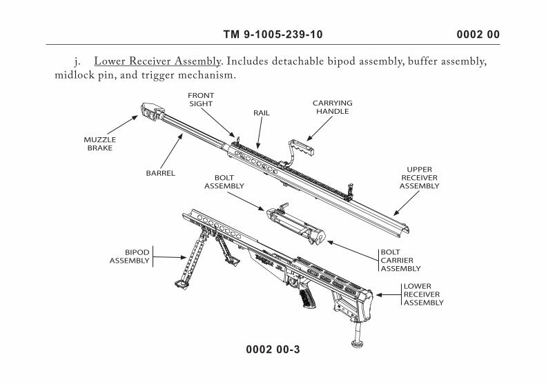
LOCATION AND DESCRIPTION OF MAJOR COMPONENTS a. Upper Receiver Assembly. Includes the front sight, rail, carrying handle, muzzle brake, and barrel. b. Rail. Used to attach the scope, the carrying handle, and accessory optic sights. c. Carrying Handle. Steel stock with a rubber handle. d. Front Sight. A 0.075 in (0.19cm) post with folding feature. e. Muzzle Brake. Critical to the functioning of the weapon; absorbs approximately 70 percent of the recoil. f. Barrel. Length is 29 in. (73.7 cm) with eight lands. Muzzle end is threaded to accept a muzzle brake; breech end has a barrel extension integral to the locking function. g. Bolt Assembly. Houses the extractor, and ejector. h. Bolt Carrier Assembly. Consists of the bolt, all extraction and ejection mechanisms, blow back mechanism, cocking lever, and sear. i. Bipod Assembly. Detachable forward support system composed of retractable legsand extending foot pads.
TM 9-1005-239-10 0002 00
0002 00-3
j. Lower Receiver Assembly. Includes detachable bipod assembly, buffer assembly, midlock pin, and trigger mechanism.
TM 9-1005-239-10
0002 00-4
TM 9-1005-239-10 0002 00
Table 1. Specifications and Capabilities. Specification Weight Overall length assembled Length in takedown mode Barrel length Magazine capacity Stock Safety Muzzle velocity Maximum range Maximum effective range Muzzle energy Magazine weight
10.4 kilograms (unloaded) 144 cm 102.5 cm 73.66 cm 10 rounds Integral with lower receiver assembly (steel) Manual thumb-lever Approx. 80 meters/sec Approx. 100 meters 50 meters 1.5 joules Ten rounds 1.2 kilograms.
EQUIPMENT DATA
END OF WORK PACKAGE
TM 9-1005-239-10 0003 00
0003 00-1
OPERATORLONG RANGE SNIPER RIFLE, M107
NSN 1005-01-469-2133THEORY OF OPERATION
CYCLE OF OPERATION
The cycle of operation for the M107 Rifle is broken down into eight basic steps (more than one step may occur at the same time). 1. Feeding: The force of the mainspring pushes the bolt forward toward the barrel extension, stripping a cartridge from the magazine and loading it into the chamber (by hand when first loading, by semiautomatic action afterwards). 2. Chambering: The bolt forces the round fully into the firing chamber, and the extractor snaps over the case rim. Blockages (dirt or debris) can prevent full chambering, as can dirty, bent, dented, or otherwise faulty ammunition. 3. Locking: During chambering the bolt enters the barrel extension, and the boltlatch engages the bolt latch trip (inside-top of the upper receiver assembly, just behindbarrel extension). The bolt latch is then depressed, allowing the bolt to retract into the bolt carrier.
TM 9-1005-239-10 0003 00
0003 00-2
4. Firing: Pulling the trigger pivots it on the trigger housing pin and presses on the transfer bar, causing the bar to rise. The transfer bar engages the sear (housed in the bolt carrier), forcing it upward and out of engaement with the striker. The striker, under spring power, forces the bolt forward to strike the gas valve of the cartridge.
5. Blowbacking: When the cartridge is fired, gas pressure exerts a thrust on the bolt carrier through the bolt. The bolt carrier carries the bolt to the rear and separates the bolt from the barrel extension.
6. Cocking: As the bolt recoils to the rear, the cocking lever "rides" the transfer barback and down, causing it to disconnect from the trigger. After disconnection, the cocking lever swings on its pin and overrides the transfer bar. The other end of the cocking lever protrudes into the bolt carrier and into the striker. As the cocking lever pivots, it withdraws the striker and compresses the striker spring. The striker then catches the sear.
7. Extraction: As the bolt withdraws from the barrel and the bolt latch locks the boltin its extended position. The extractor located on the bolt face and hooked over the rimof the fired case, pulls the case from the firing chamber.
8. Ejection: As soon as the fired case has been extracted and has cleared the rear ofthe barrel extension, it is expelled from the rifle by the spring-powered ejector.
END OF WORK PACKAGE
TM 9-1005-239-10
CHAPTER 2
OPERATOR INSTRUCTIONSFOR
LONG RANGE SNIPER RIFLE, M107
TM 9-1005-239-10 0004 00
0004 00-1
OPERATORLONG RANGE SNIPER RIFLE, M107
NSN 1005-01-469-2133DESCRIPTION AND USE OF OPERATOR CONTROLS
GENERAL
The following paragraph contains an illustration that shows the location of each control for the M107 Long Range Sniper Rifle (LRSR). The numbers on the illustration are keyed tothe tabular listing which contains the name and functional description of the controls.
TM 9-1005-239-10
0004 00-2
0004 00
CONTROLS
Table 1 describes the controls for the sniper rifle. The key number in the table corresponds with the callout number in the illustration.
1
2
TM 9-1005-239-10 0004 00
0004 00-3
KEY CONTROL FUNCTION OR USE
1
2
Trigger
Safety Switch
Fires the weapon by squeezing toward the rear of the rifle. Prevents and allows firing of the rifle.
Table 1. M107 Sniper Rifle Controls.
END OF WORK PACKAGE
TM 9-1005-239-10
INITIAL SETUP:Tools and Consumables 12gram / 12oz threaded Co2 cartridge 8mm BB bullets
0005 00
0005 00-1
OPERATORLONG RANGE SNIPER RIFLE, M107
NSN 1005-01-469-2133OPERATION UNDER USUAL CONDITIONS
TM 9-1005-239-10
ASSEMBLE THE CO2 CHARGER
0005 00-2
12g12oz
0005 00
For 12oz threaded Co2 cartridgeFor 12gram Co2 cartridge
TM 9-1005-239-10
(1) Loading the 8mm BB bullet (2) Charging the Co2 vertically.
LOADING BB AND CHARGING CO2
0005 00-3
0005 00
Gas pressure is too low will cause the system operational failures.
CAUTION
TM 9-1005-239-10 0005 00
0005 00-4
LOADING THE MAGAZINE
1. Center a cartridge (1) between the feed lips (2) in the magazine (3) and pressdown until the cartridge snaps under the lips.
The magazine has a ten round capacity. The preferred load is 8 to 9 rounds. Load no more than 9 rounds or damage will occur.
CAUTION
2. Ensure the cartridges are pushed all the way to the rear and that there is no interference between the magazine (3) and the nose of the cartridges.
TM 9-1005-239-10 0005 00
0005 00-5
Push Round Down and Back
LOADING THE MAGAZINE - Continued
TM 9-1005-239-10 0005 00
0005 00-6
INSERTING THE MAGAZINE INTO WEAPON
Ensure the safety is in the "safe" position and that the chamber is clear of any obstruction.
WARNING
1. Prior to inserting the magazine (1), grasp the charging handle (2) and dry-cyclethe weapon several times (work the bolt all the way back and forth). If any damage has occurred to either the upper or the lower receiver assemblies during shipping, the boltcarrier will not move freely.
2. Insert the magazine (1) into the magazine well of the lower receiver assembly, tilting the magazine so that the bullets point upward. Place the magazine hook (3), located on the front of the magazine, onto the hinge, located in the front of the magazine well. Now rotate the magazine upwards until you hear the click of it locking into the rear magazine catch (4).
TM 9-1005-239-10 0005 00
0005 00-7
1
3
4
2
INSERTING THE MAGAZINE INTO WEAPON - Continued
TM 9-1005-239-10
0005 00-8
0005 00
NOTEEnsure the magazine hook (3) is in the correct space. Tugging on the magazine is a good check for proper seating.
3
TM 9-1005-239-10 0005 00
0005 00-9
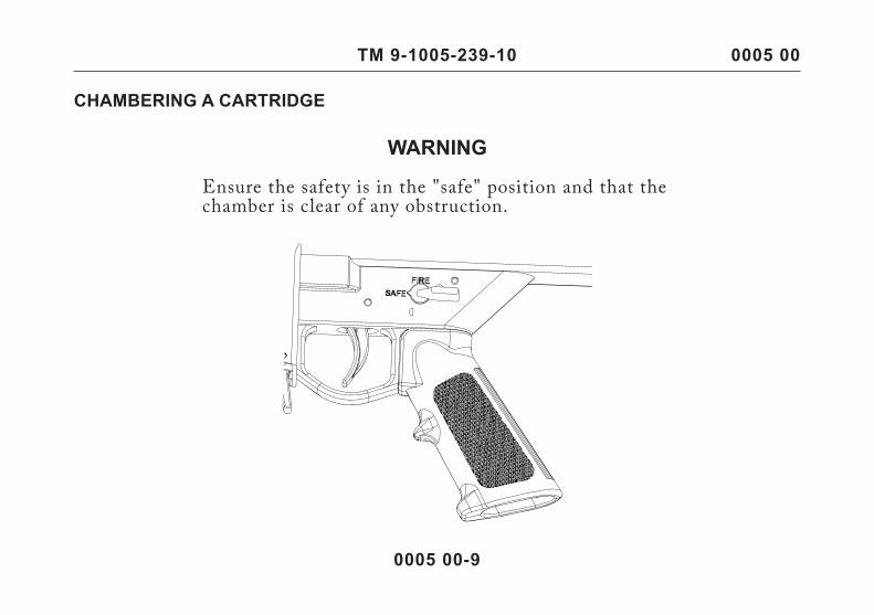
CHAMBERING A CARTRIDGE
WARNING
Ensure the safety is in the "safe" position and that thechamber is clear of any obstruction.
TM 9-1005-239-10
WARNING
WARNING
Never try to force a cartridge into the chamber. If the bolt does not fully close, clear any obstructions until a round is successfully chambered. Never attempt to fire a round if thebolt does not fully close.
Because the rifle is recoil-operated, the shooter must be positioned squarely behind the weapon, with the recoil pad firmly against the shoulder. Anything less may result in injury, discomfort, or failure of the action to cycle correctly.
1. With the muzzle pointed down range and in a safe direction, move the bolt handleup and all the way to the rear. Release the bolt handle chambering the first round from the magazine. Tap the bolt handle to ensure the bolt is fully forward.
2. Shooter is positioned squarely behind the rifle. Rotate safety selector switch to the "FIRE" position. Ensure shoulder pad is properly positioned on shoulder before squeezing the trigger. The rifle will fire one round for each squeeze of the trigger until the magazine and chamber are empty.
0005 00-10
0005 00
TM 9-1005-239-10
WARNING
UNLOADING THE RIFLE
The bolt does not automatically remain to the rear when the rifle or magazine is empty. After the rifle is unloaded, and with the charging handle to the rear, always physically check the chamber to ensure that the rifle is empty.
3. With the safety in the "safe" position and the muzzle pointed in a safe direction, pull the charging handle to the rear until it stops, then release it. The rifle then loads and locks under its own spring power.
0005 00
0005 00-11
1. Place the weapon safety on "safe". Press the magazine catch (1) forward towards the magazine (2), and remove the magazine.
CHAMBERING A CARTRIDGE - Continued
TM 9-1005-239-10
0005 00-12
0005 00
2. Pull the charging handle (3) to the rear, which will eject any cartridge still chambered.
NOTERemember that the bolt does NOT automatically remain to the rear when the rifle or magazine is empty.
TM 9-1005-239-10 0005 00
UNLOADING THE MAGAZINE
CAUTIONOnly remove ammunition from the magazine with your hands.
Hold the magazine (1) with one hand with the cartridge tips (2) facing away from you. Push each of the cartridges out of the magazine until all are ejected.
0005 00-13
3. After the rifle is unloaded, and with the charging handle (3) to the rear, look into the chamber make certain the breech area and chamber are empty.
UNLOADING THE RIFLE - Continued
TM 9-1005-239-10
END OF WORK PACKAGE
0005 00-14
0005 00
Push Round Forward
TM 9-1005-239-10
OPERATORLONG RANGE SNIPER RIFLE, M107
NSN 1005-01-469-2133SIGHTING SYSTEMS
0006 00
0006 00-1
TM 9-1005-239-10
0006 00-2
0006 00
ZEROING THE IRON SIGHT
1. Assume a prone-supported firing position 100 meters from the zero target (NSN 6920-00-900-8205). Align index line with the 100-meter range line on the elevation scale (1).
2. Align windage index line with windage zero index line on base of iron sight. Align the rear peep sight (2) with the front sight post (3).
TM 9-1005-239-10 0006 00
0006 00-3
3. Obtain the proper sight picture by aligning the rear peep sight (2) with front sight post (3). Fire a three round shot group at center mass of the zero target, maintaining the same aim point with each shot. Note the strike of the rounds and make windage andelevation adjustment accordingly.
4. Continue firing three round shot groups, making windage and elevation adjustments as necessary until the shot group is center mass on the zero target.
5. Once the shot group is center mass, loosen the screw (6) on the elevation scale (1). Slide the elevation scale until the 100 meter range index line is aligned with the index lineon the rear peep sight (2), tighten the screw.
NOTEOne click of elevation knob (4) moves the strike of the round 1.6 in. (4.06 cm) at 100 meters.
One click of windage knob (5) moves the strike of the round 0.75 in. (1.90 cm) at 100 meters.
END OF WORK PACKAGE
ZEROING THE IRON SIGHT - Continued
TM 9-1005-239-10
CHAPTER 3
MAINTENANCE INSTRUCTIONSFOR
LONG RANGE SNIPER RIFLE, M107
TM 9-1005-239-10 0007 00
0007 00-1
OPERATORLONG RANGE SNIPER RIFLE, M107
NSN 1005-01-469-2133FIELD STRIPPING
TM 9-1005-239-10
0007 00-2
0007 00
INTRODUCTION
The M107 is field stripped into three major components: upper receiver assembly (1), lower receiver assembly (2), bolt and carrier assemblies (3).
TM 9-1005-239-10
0007 00-3
0007 00
FIELD STRIPPINGWARNING
Ensure that the weapon is unloaded and on SAFE before performing these procedures.
1. Remove rear lock (1) and midlock (2) pins by press the button of pin and pull it out.
1
2
TM 9-1005-239-10 0007 00
0007 00-4
2. Grasp charging handle (3) on the bolt carrier (4) and pull to the rear until the bolt (5) clears the barrel extension.
TM 9-1005-239-10 0007 00
0007 00-5
FIELD STRIPPING - Continued
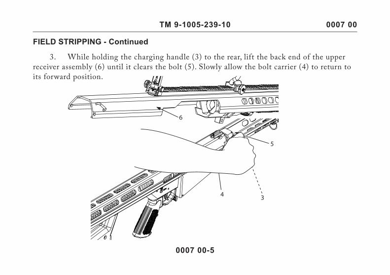
3. While holding the charging handle (3) to the rear, lift the back end of the upper receiver assembly (6) until it clears the bolt (5). Slowly allow the bolt carrier (4) to return toits forward position.
TM 9-1005-239-10
9
87
6
0007 00-6
0007 00
4. Disengage front hook (7) from the front hook pin (8) on the lower receiver (9) and lift upper receiver assembly (6) clear of lower receiver assembly.
TM 9-1005-239-10
6. Pull the bolt carrier (4) rearward and insert the midlock pin (1) through the buffer (10) and buffer spring (11).
FIELD STRIPPING - Continued
WARNING
Buffer and buffer spring are under heavy spring tension.
0007 00
0007 00-7
4
101
11
TM 9-1005-239-10
7. Gently pull the bolt carrier (4) forward and lift out of the lower receiver assembly (9).
CAUTIONWhen removing the bolt carrier from the lower receiver assembly, ensure carrier is completely forward of the housing before lif ting bolt to avoid damaging lower receiver assembly.
4
1
9
0007 00-8
END OF WORK PACKAGE
TM 9-1005-239-10
0008 00-1
0007 00
OPERATORLONG RANGE SNIPER RIFLE, M107
NSN 1005-01-469-2133EXTRACTOR MAINTENANCE
TM 9-1005-239-10 0008 00
0008 00-2
WARNING
Always point the bolt away from face and eyes to avoid possible injury if parts fly free.
CAUTION
Cover plunger and plunger spring with thumb while sliding extractor out of slot to prevent loss or damage.
NOTE
Per form Remova l p rocedure on l y upon ex t r ac tor, extractor plunger or extractor spring failure.
REMOVAL
TM 9-1005-239-10
0008 00-3
0008 00
1. To remove the extractor (1) from the bolt (2), depress the extractor plunger by inserting a 1/16 in. punch through the extractor hole (3).
2
3
1
REMOVAL - Continued
TM 9-1005-239-10
0008 00-4
0008 00
2. Slide the extractor (1) out of the slot. Remove extractor plunger (3) and extractor spring (5). Visually inspect all components for damage.
INSTALLATION
1. Insert extractor spring (5) and extractor plunger (3) into bolt (2).
2. Slide the extractor (1) into the slot.
END OF WORK PACKAGE
1
2
53
TM 9-1005-239-10
0009 00-1
0009 00
OPERATORLONG RANGE SNIPER RIFLE, M107
NSN 1005-01-469-2133MAINSPRING AND MAINSPRING BUFFER MAINTENANCE
TM 9-1005-239-10
0009 00-2
0009 00
REMOVAL
1. Using your finger, push the mainspring buffer (1) to the rear and place the rear lock pin (2) through the coils of the mainspring (3) and the ports in the mainspring housing(4).
2. Place your finger into the slot on the lower end of mainspring buffer (1), and turn the mainspring buffer so that the groove on the flange lines up with the buffer stop (5) on the lower receiver assembly (6). Remove the rear lock pin (2). Slowly and carefully remove the mainspring buffer (1) and mainspring (3).
4
2
1
6
5
3
TM 9-1005-239-10
0009 00-3
0009 00
INSTALLATION
1. Slide the mainspring (1) into the lower receiver assembly (2). Place the mainspring buffer (3) into the mainspring. Guide the mainspring into the housing (4) untilthe mainspring buffer is even with the housing. Place your finger into the slot on the mainspring buffer, and turn the mainspring buffer so that the grove in its flange lines up with the buffer stop (5) on the lower receiver assembly.
4
2
1
5
3
TM 9-1005-239-10 0009 00
0009 00-4
2. Push the mainspring buffer (3) to the rear of the housing (4) and secure it by placing the rear lock pin (6) through coils of the mainspring (1) and the ports in the mainspring housing. Using your finger, ensure that the groove and slot are NOT aligned. Remove the rear lock pin. Ease off the pressure until the mainspring buffer stops on the buffer stop (5).
END OF WORK PACKAGE
4 1
6
53
TM 9-1005-239-10
0010 00-1
0010 00
OPERATORLONG RANGE SNIPER RIFLE, M107
NSN 1005-01-469-2133BARREL MAINTENANCE
TM 9-1005-239-10
0010 00-2
0010 00
ASSEMBLY
1. Carefully pick up the upper receiver assembly (1). The barrel (2) will be nested inside the receiver for compact storage and transit. Move the impact bumpers (3) into position on either side of the receiver’s central barrel bushing, so that they rest snugly against the bushing.
2. Align the barrel (2) so that its feed ramp (slanted entry to the firing chamber) is on the bottom. Keeping fingers away from the barrel, hold the upper receiver assembly (1) horizontally, then tilt it in the direction of the muzzle (4). The barrel should fall into place, at its full forward extension into the upper receiver assembly.
4
1
2 3
TM 9-1005-239-10 0010 00
0010 00-3
3. The barrel springs (5) at the front of the upper receiver assembly (1) are held together by the barrel key (6) which acts as a spring yoke. Maintaining the downward tilt of the upper receiver assembly (to keep the barrel in place) firmly grasp the barrel key-not the springs-and pull it into place on the forward slot of the barrel. Work the barrel key fromside to side until it is firmly seated in the barrel slot. The upper receiver assembly is nowfully assembled.
WARNINGThe tension on the barrel springs is about 70 pounds. Serious injury may result if springs are released suddenly.
Incomplete or improper assembly may result in injury.
5 1
6
ASSEMBLY - Continued
TM 9-1005-239-10
0010 00-4
0010 00
STORAGE CAUTION
Do not pull on barrel springs to remove the barrel key. Doing so may damage the springs.
Barrel spring is under tension.
1. To nest the barrel (1) for storage and transit, it is necessary to remove the barrel key (2) from the barrel key slot.
2. Withdraw the barrel key (2) from the slot in the barrel (1) by slowly working it out. Slide the barrel out the rear of the upper receiver assembly (3).
2END OF WORK PACKAGE
TM 9-1005-239-10TM 9-1005-239-10
CHAPTER 4
SUPPORTING INFORMATION
TM 9-1005-239-10
INTRODUCTIONExplanation of Columns in the Sniper Weapons System Parts ListColumn (1) Illus Number. Gives you the number of the item illustrated.
Column (2) Description. Identifies the item name.
Column (3) Qty. Indicates the quantity required.
OPERATORLONG RANGE SNIPER RIFLE, M107
NSN 1005-01-469-2133SNIPER WEAPONS SYSTEM PARTS LIST
0011 00-1
0011 00
TM 9-1005-239-10TM 9-1005-239-10 0011 00
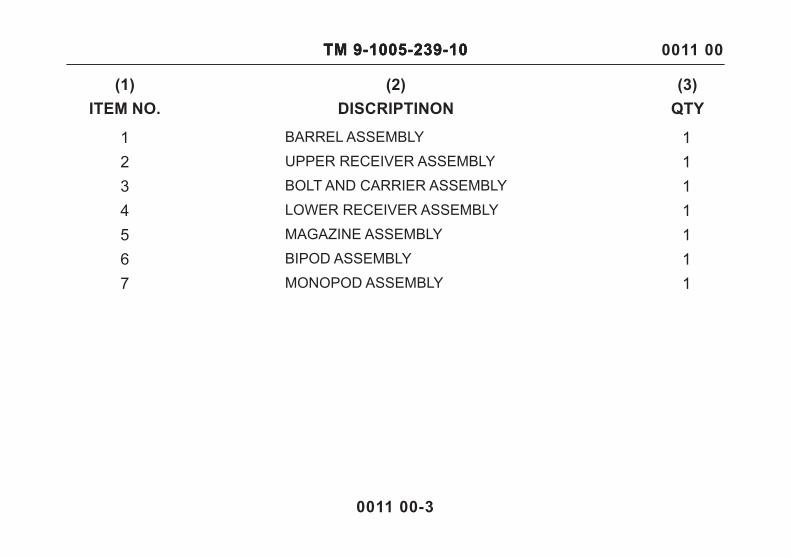
Figure 1. Long Range Sniper Rifle (LRSR), M107.
0011 00-2
1
23
4
7
65
TM 9-1005-239-10TM 9-1005-239-10TM 9-1005-239-10
0011 00-3
0011 00
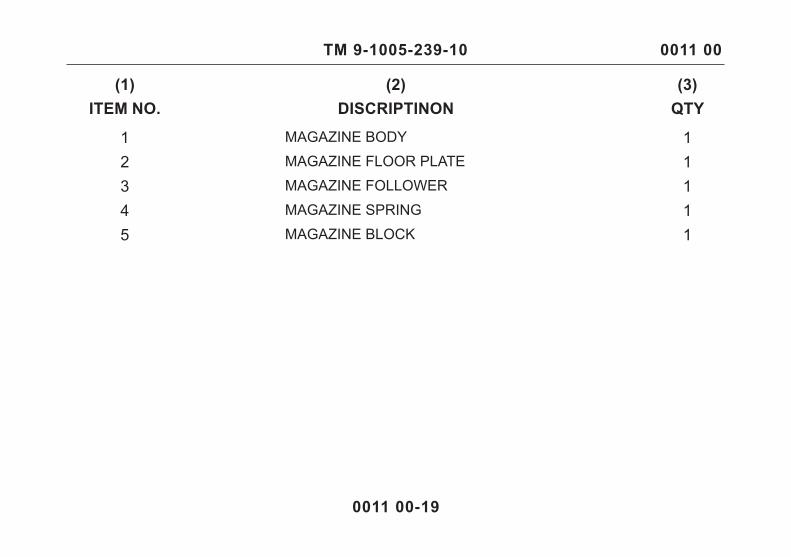
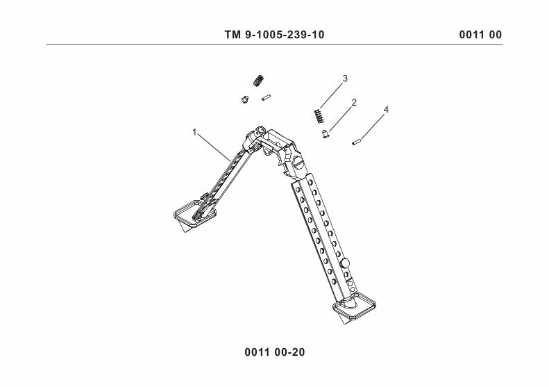
(1)ITEM NO.
(2)DISCRIPTINON
(3)QTY
1 1 BARREL ASSEMBLY
2 1 UPPER RECEIVER ASSEMBLY
3 1 BOLT AND CARRIER ASSEMBLY
4 1 LOWER RECEIVER ASSEMBLY
5 1 MAGAZINE ASSEMBLY
6 1 BIPOD ASSEMBLY
7 1 MONOPOD ASSEMBLY
TM 9-1005-239-10
0011 00-4
0011 00
3
1
14
1216
2217
5
24
1921
20
6
7
8
10
9
11
15
13
18
TM 9-1005-239-10 0011 00
0011 00-5
8 1 HOP UP BASE
9 1 HOP UP BASE COVER10 1 GAS VALVE STRIKER
(1)ITEM NO.
(2)DISCRIPTINON
(3)QTY
1 1 MUZZLE BRAKE2 2MUZZLE BRAKE SCREW
3 2MUZZLE BRAKE WASHER4 1 OUTER BARREL
5 2 INNER BARREL BLOCK6 1 INNER BARREL
7 1 HOP UP
11 4BARREL SCREW
(1)ITEM NO.
(2)DISCRIPTINON
(3)QTY
13 1 HOP UP SCREW12 1 BARREL IMPACT BUMPER
14 1 HOP UP SPACER15 1 SHELL HOLDER SPRING16 1 CHAMBER17 1 BATTERY BUMPER