TM 9-1265-375-10 Supersedes copy dated 18 October 1984 OPERATOR’S MANUAL FOR MULTIPLE INTEGRATED LASER ENGAGEMENT SYSTEM (MILES) SIMULATOR SYSTEM, FIRING LASER: M83 (NSN 1265-01-158-4560) FOR M2/M3 FIGHTING VEHICLES DISTRIBUTION STATEMENT A. Approved for public release; distribution is unlimited. HEADQUARTERS, DEPARTMENT OF THE ARMY AUGUST 1988
Transcript
TM 9-1265-375-10Supersedes copy dated 18 October 1984
DISTRIBUTION STATEMENT A. Approved for public release; distribution is unlimited.
HEADQUARTERS, DEPARTMENT OF THE ARMYAUGUST 1988
TM 9-1265-375-10
WARNING
STAY OUT OF THE DANGER ZONECAUTION 1: CAUTION 2:Ear Damage Flying Debris
Never stand within the danger zone while loading the ATWESS. Always stand to the right side of the rear of the launcher.After the cartridge is inserted into the chamber, keep hands, arms, and other portions of the body away from the hole inthe center of the breech door. Failure to follow these instructions could result in personnel being burned by the backblastescaping through the hole in the center of the breech door.
Never arm an ATWESS until you are ready to fire.
Treat the TOW/MILES as you would any loaded and armed weapon. Do not drop TOW/MILES when ATWESS is loadedand armed. A strong jolt may set off the ATWESS.
Handle ATWESS cartridges with the same care you use with any live ammunition.
Always wear earplugs when firing the TOW/MILES.
Although the laser light emitted by MILES Laser Transmitters is considered eye safe by the Bureau of Radiological Health,suitable precautions must be taken to avoid possible damage to the eye from overexposure to this radiated energy. Takethe following precautions:
• Never look at the laser emitter at close range (less than 12 meters).• Never look at the laser emitter through optics such as BINOCULARS, TELESCOPES, or weapon sights at
ranges less than 75 meters.• Never look at the laser emitter directly along the axis of the bore of the weapon.
a
TM 9-1265-375-10
Primer is highly inflammable. Do not spray near Heat, Sparks, or Open Flame. No Smoking. Use only in well-ventilatedarea.
Ensure personnel stand clear of moving Launcher. Failure to comply may cause Injury or Death to personnel.
Do not install TOW simulator tubes containing ATWESS cartridges.
Use Manual Elevation Controls to raise or lower gun as required. Use of power controls could result in serious injury topersonnel.
Make sure turret area is clear of personnel if TOW launcher is raised in power mode. Turn TURRET DRIVE SYSTEM toOFF after TOW launcher is up and locked.
Sudden turret movement can injure personnel. Make sure TURRET DRIVE SYSTEM switch is OFF when testingtransmitters.
The M82 blank is the only ammunition authorized for use in the M240C Coax machine gun.
Treat ATWESS cartridges as you would live ammunition. A strong shock may set off the ATWESS cartridge.
Accidental turret movement may cause personnel injuries and errors in MILES alignment.
Make sure TURRET DRIVE SYSTEM is OFF.
Never stand behind TOW simulator when arming it or loading ATWESS cartridges.
Do not load the TOW simulator from the cargo hatch. ATWESS misfire could injure personnel inside vehicle.
Load from Gunner’s station hatch by reaching around from simulator side. Always load outboard TOW simulator tube first.Accidental ATWESS firing could injure Loader.
Observe 10 second delay after first arming.
For Information on FIRST AID, see FM 21-11.
b
TM 9-1265-375-10
TECHNICAL MANUAL HEADQUARTERSNo. 9-1 265-375-10 DEPARTMENT OF THE ARMY
WASHINGTON, D. C., 12 AUGUST 1988OPERATOR’S MANUAL
FORMULTIPLE INTEGRATED LASER ENGAGEMENT SYSTEM
(MILES)SIMULATOR SYSTEM, FIRING, LASER: M83
NSN 1265-01-158-4560FOR
M2/M3 FIGHTING VEHICLES
REPORTING ERRORS AND RECOMMENDING IMPROVEMENTS You can help improve this manual. Ifyou find any mistakes or if you know of a way to improve the procedures, please let us know. Mail yourletter, DA Form 2028 (Recommended Changes to Publications and Blank Forms), or DA Form 2028-2located in back of this manual direct to: Commander, US Army Armament, Munitions and ChemicalCommand, ATTN.: AMSMC-MAS, Rock Island, IL 61299-6000. A reply will be furnished to you.
DISTRIBUTION STATEMENT A. Approved for public release; distribution is unlimited.
TABLE OF CONTENTSPage
CHAPTER 1 INTRODUCTION ............................................................................................................................1-1SECTION I General Information .........................................................................................................1-1SECTION II Equipment Description .....................................................................................................1-5SECTION III Technical Principles of Operation ..................................................................................1-10
CHAPTER 2 OPERATING INSTRUCTIONS.......................................................................................................2-1SECTION I Description and Use of Operator’s Controls and Indicators .............................................2-1SECTION II Preventive Maintenance Checks and Services................................................................2-4SECTION III Operation Under Usual Conditions...................................................................................2-7SECTION IV Operation Under Unusual Conditions...........................................................................2-110
CHAPTER 3 MAINTENANCE INSTRUCTIONS..................................................................................................3-1SECTION I Lubrication Instructions ....................................................................................................3-1SECTION II Troubleshooting Procedures ............................................................................................3-2
APPENDIX A REFERENCES..................................................................................................................... A-1
APPENDIX B COMPONENTS OF END ITEM AND BASIC ISSUE ITEMS LISTS .................................... B-1
APPENDIX C ADDITIONAL AUTHORIZATION LIST................................................................................. C-1
APPENDIX D EXPENDABLE/DURABLE SUPPLIES AND MATERIALS LIST .......................................... D-1
INDEX .................................................................................................................................. Index-1
*Supersedes TIM 9-1265-375-10 dated 18 October 1984 , including all changes.
i(ii blank)
TM 9-1265-375-10
CHAPTER 1INTRODUCTION
SECTION I. GENERAL INFORMATION
SCOPE
TYPE OF MANUAL. This manual shows you how to install, operate and maintain MILES simulator system equipment forthe M2 and M3 Fighting Vehicles. Step-by-step instructions are given for all procedures necessary to use the system.
This manual covers only authorized operator maintenance. Any maintenance problems not coveted should be referred toorganizational maintenance personnel.
NOTE
To use this manual you should be able to:
Aim and Fire all M2/M3 Vehicle weapons (see TM 9-2350252-10).
Install blank-fire adapter on the M240C machine gun (see TM 9-1005-313-10).
Complete DA Form 2402 and 2404.
If you cannot do these tasks, ask your NCOIC or Instructor to showyou how. When you can do all these tasks, go on with this manual.
1-1
TM 9-1265-375-10
SCOPE (Continued)
PURPOSE OF EQUIPMENT. MILES equipment for the M2 and M3 Fighting Vehicles consists of two battery-operatedlaser transmitters and a detector system. It permits realistic combat training without the hazards of using live ammunition.
LIMITATION ON EQUIPMENT. MILES-equipped weapons have the same range and operational capabilities as thenormal weapons, but a dirty laser transmitter lens may reduce the effective range of the transmitters.
MAINTENANCE FORMS AND RECORDS. Department of the Army forms and procedures used for equipmentmaintenance will be those prescribed by DA PAM 738-750, The Army Maintenance Management System (TAMMS).
HAND RECEIPT MANUAL. This manual has a companion document with a TM number followed by "-HR" (which standsfor Hand Receipt). The TM 9-1265-375-10-HR consists of preprinted hand receipts (DA Form 2062) that list end itemrelated equipment (i.e., COEI, BII, and AAL) you must account for. As an aid to property accountability, additional -HRmanuals may be requisitioned from the following source in accordance with procedures in Chapter 3, AR 310-2:
Commander
The U. S. Army Adjutant General Publications Center
2800 Eastern Boulevard
Baltimore, MD 21220
REPORTING EQUIPMENT IMPROVEMENT RECOMMENDATIONS (EIRS). If your MILES equipment for the M2 and M3Fighting Vehicles needs improvement, let us know. Send us an EIR. You, the user, are the only one who can tell us whatyou don’t like about your equipment. Let us know why you don’t like the design or performance. Put it on an SF 368(Quality Deficiency Report). Mail the Quality Deficiency Report to us at Commander, U. S. Army Armament, Munitionsand Chemical Command, ATTN: AMSMC-QAD, Rock Island, IL 61299-6000. We’ll send you a reply.
TOW Tube Launched, Optically Sighted, Wire Command Link-Guided Missile
TOW Transmitter Transmitter Assembly, Simulator System, Laser: TOW
TOW Simulator Tube Simulator, Anti-Tank Missile Fire, TOW
LIST OF ABBREVIATIONS
CLP Cleaner, Lubricant and Preservative
CVKI Combat Vehicle Kill Indicator
LCA Loader’s Control Assembly
MILES Multiple Integrated Laser Engagement System
MWLD Man-Worn Laser Detector
NCOIC Non-Commissioned Officer In Charge
TOW Tube Launched, Optically Tracked, Wire-guided
GLOSSARY
ATWESS Cartridge Pyrotechnic device used to simulate backfire shock and noiseof TOW firing.
1-3
TM 9-1265-375-10
GLOSSARY (Continued)
Common Name Official Nomenclature
Control Console (Loader’s MILES device used in vehicles to decode laser beam signalsControl Assembly - LCA) and fire laser transmitters.
Controller Umpire or Referee in a MILES training exercise.
Controller Gun Device used to test MILES detector systems. Also used todisqualify soldiers or vehicles from an exercise.
Controller Key Green Key used by Controller to reset MILES transmitters.
Combat Vehicle Kill Indicator MILES device attached to armored vehicles to provideexternal flashing light. Indicates that vehicle is underopposing fire ("NEAR MISS"), has been "HIT" or "KILLED."
Fastener Tape Hook-and-pile tape. Used to hold Vehicle detector belts andother MILES equipment in place.
Helmet Harness Part of the laser detector assembly worn on a combat helmet.
HIT Simulated contact with opposing fire insufficient to disablevehicle or cause a fatality.
KILL Simulated contact with opposing fire sufficient to disablevehicle or cause a fatality.
Laser Beam Invisible beam of light which simulates weapon fire in MILES.
Laser Detector Belt Assembly Device that senses the laser beam directed at it.
Laser Transmitter Device that sends the laser beam.
Man-Worn Laser Detector Helmet and torso assembly worn by personnel which sensesa laser beam directed at it.
NEAR MISS Simulated closeness to contact with opposing fire.
Simulator Training device which takes the place of real equipment andwhich has many of its characteristics.
Torso Harness Part of the laser detector assembly worn on the upper body.
TOW Wire-guided anti-tank missile.
Orange Weapon Key Silences intercom when inserted in control console. Alsoused to "SELF-KILL" vehicle.
Yellow Weapon Key Carried by vehicle personnel wearing MWLDs. Whencontinuous alarm sounds, it is put in the MWLD keyreceptacle to silence alarm.
1-4
TM 9-1265-375-10
SECTION II. EQUIPMENT DESCRIPTION
EQUIPMENT CHARACTERISTICS, CAPABILITIES, AND FEATURES
PURPOSE OF MILES SIMULATOR SYSTEM, LASER: M2/M3 FIGHTING VEHICLES
The MILES Simulator System, Laser: M2/M3 Fighting Vehicles, permits the Vehicle and Crew to take part in realisticcombat training exercises. Actual firing conditions of all vehicle weapons are simulated using laser beams. Blankammunition and an ATWESS firing device add to the system’s realism.
Laser detectors mounted on the M2 and M3 vehicles and worn by crew members sense enemy fire.MILES system electronics determine the accuracy and simulated damage of enemy fire. The system also detects the typeof weapon directing enemy fire against the M2 and M3 vehicles.
FEATURES AND CAPABILITIES
• Easily installed and removed.
• Simulates firing capability of all M2 and M3 weapons.
1. 25 mm Main Gun/Coax M240C Machine Gun
2. TOW Missile
• Blank-Fire, FLASHWESS, and ATWESS firing devices add realism.
Main Gun/Coax Machine Gun Transmitter (1). Simulates firing effects of 25 mm Main Gun and M240C Coax MachineGun by transmitting a special coded laser signal. Mounts on barrel of 25 mm main gun.
Blank Firing Attachment (2). Permits using blank ammunition in M240C machine gun.
Combat Vehicle Kill Indicator (3). Flashes strobe light for a "KILL," "HIT," or "NEAR MISS" indication. Mounts on topright side of the Integrated Sight Unit (ISU).
FLASHWESS (4). Lamp device powered by 24 V dc vehicle power. Flashes 120 times per minute when activated by gunsystem. Simulates light flashes generated by firing live ammunition. Attaches to main gun barrel.
Detector Belt System (5). Receives laser pulses from MILES-equipped opposing weapons. Generates, amplifies androutes electrical signals to the control console for determining whether signal was a "NEAR MISS," "HIT," or "KILL."Mounts on TOW launcher and sides, front, and rear of M2 and M3 vehicles.
TOW Transmitter (6). Simulates firing effects of TOW missile by transmitting a special coded laser signal. Attaches toside of raised TOW launcher.
1-6
TM 9-1265-375-10
TOW Simulator (ATWESS) Tube (7). Simulates firing signature of TOW missiles. Mounts inside TOW launcher.
LOCATION AND DESCRIPTION OF MAJOR COMPONENTS (CONT.)
Control Console (Loader’s Control Assembly LCA) (9). Receives detected laser pulse signals from detectorassemblies. Decodes these signals, and actuates appropriate audio and visual alarms. Provides electrical signals to firemain gun or machine gun and TOW transmitters. Contains a key receptacle for initializing system, silencing intercomalarm, and resetting system. Mounts on top of the HE ammunition cover.
Battery Box (10). Contains two 6-volt batteries for operating main gun or machine gun and TOW laser transmitters,control console, and detector belts. Mounts on top of the control console.
25 mm/Coax Machine Gun 4.50 2.2 x 8.0 x 10.5 1500/4500* 25-3000/25-1000
TOW 4.50 5.7 x 2.0 x 10.5 12 65-3750
Detector Assemblies Weight Dimensions Number of Detectors(Pounds) (Inches)
Belt #7 3.00 191 x 2 5
Belt #8 2.63 177 x 2 4
Man-Worn Helmet Harness 1.56 11.0 (dia.) x 3.5 5
Man-Worn Torso Harness 2.81 40 x 7.75 to 18 x 2 8
Equipment Weight Dimensions(Pounds) (Inches)
CVKI (without adapter) 11.62 14 x 7.3 (diameter)
Control Console (LCA) 8.50 8.5 x 5.5 x 5.5(without adapter)
Battery Box Assembly 1.31 7 x 5 x 4
TOW Simulator 20.00 56 x 8.0 (diameter)
FLASHWESS 8.5 6 x 5.1 (diameter)
*Dry-fire mode
1-9
TM 9-1265-375-10
SECTION III. TECHNICAL PRINCIPLES OF OPERATION
BASIC PRINCIPLES OF OPERATION
The MILES system uses semiconductor laser beams to simulate actual weapon fire. An eye-safe invisible laser beam issent out by each weapon’s transmitter when it is fired. The laser beam is coded and simulates all of the weapon’scapabilities including range, accuracy, and destructive capability.
Laser detector systems are used to sense opposing fire. The detector systems register opposing laser beams anddetermine whether they have scored a "NEAR MISS," "HIT," or "KILL." The systems activate alarms indicating thepresence and damage of opposing fire.
The MILES system of laser beam transmitters and detectors allows safe, realistic training exercises with a complete rangeof weaponry and vehicles.
MILES M2/M3 FIGHTING VEHICLE CONFIGURATION
All weapons on the M2/M3 Fighting Vehicles are equipped with laser transmitters that are fired using normal weaponoperating procedures. The vehicle exterior has special detector belts attached that sense opposing fire. A control consolemounted inside the vehicle determines the extent of opposing fire and its effect. A flashing light (CVKI) mounted on thevehicle’s exterior is activated by the control console when opposing fire is detected.
Crew members wear MWLD torso and helmet harnesses. These detect opposing fire directed against the individual crewmember. When opposing fire is detected, an audio alarm on the torso harness is set off.
MAIN GUN MILES FIRING
The MILES-equipped main gun is fired using normal procedures. A laser transmitter mounted on the main gun barrel fireswhen the gun is triggered in either the single shot or automatic modes. A shorting plug electronically disconnects theactual main gun during MILES exercises.
The low ammunition override button on the vehicle weapon control box must be pressed before firing the main gun.
The MILES system allows a basic load of 1500 main gun rounds. After firing the main gun, you can check to see howmany rounds the MILES system has left. This is done by turning the switch on the control console to MAIN GUN, pressingthe display button, and reading the displayed number. That number multiplied by 100 represents the rounds remaining.
MAIN GUN WEAPON SIGNATURE SIMULATION
The FLASHWESS device uses a high intensity lamp to simulate the light flash of actual 25 mm main gun firing. Thedevice will flash approximately 120 times per minute. The Controller must set the key receptacle on the 25 mm guntransmitter to AWESS for FLASHWESS operation.
1-10
TM 9-1265-375-10
M240C COAX MACHINE GUN
The M240C Coax Machine Gun is fired using normal procedures. The gun is loaded with blank ammunition. The soundof blank fire is sensed by a microphone which triggers the coax machine gun transmitter mounted on the main gun barrel.
The laser transmitter will operate as long as blank ammunition is being fired. The control console will not indicate roundsremaining when using blank ammunition.
The machine gun may also be operated in a dry-fire mode without using blank ammunition. A dry-fire plug, P/N 19200-11749794 is required to operate in this mode.
The low ammunition override button on the vehicle weapon control box must be pressed before firing machine gun in dry-fire mode.
The MILES system allows a basic load of 4500 M240C Coax Machine Gun rounds in the dry-fire mode.After firing the machine gun, you can check to see how many rounds the MILES system has left. This is done by turningthe switch on in the control console to COAX, pressing the display button, and reading the displayed number. Thatnumber multiplied by 100 represents the rounds remaining.
TOW SYSTEM
The TOW system is fired using normal procedures. The launcher is equipped with two TOW simulator (ATWESS) tubes.A TOW laser transmitter is mounted on the exterior of the TOW launcher.
The TOW simulator tubes are loaded with ATWESS cartridges. When the TOW weapon is fired the ATWESS cartridgesdetonate, providing noise flash and smoke simulation of an actual missile launch.
The laser transmitter fires 1 second after the ATWESS device. TOW weapon sight must be used to track target for 11seconds to secure a "HIT" or "KILL." A "HIT" or "KILL" indicates that the gunner has properly tracked the target and the 11seconds simulates a tracking time of an actual missile.
After firing the TOW weapon, you can check to see how many rounds the MILES system has left. This is done by turningthe switch on the control console to MISSILE, pressing the display button, and reading the displayed number. The TOWsystem may also be operated in a dry-fire mode without using ATWESS cartridges. The Controller must set the keyreceptacle on the TOW tube to Dry-Fire.
DRY-FIRE OPERATION
The laser transmitters on all MILES-equipped weapons can be fired without using blank ammunition or the ATWESS firingdevice. A Controller Key must be used to set the 25 mm Main Gun and TOW transmitters for dry-fire operation. The keyis inserted in a receptacle on the TOW simulator tube and selects either dry-fire or ATWESS operation. The key isinserted in a receptacle on the 25 mm main gun transmitter to select either dry-fire or operation with the FLASHWESS.
The dry-fire plug, P/N 19200-11749794 is used to dry-fire the machine gun.
1-11
TM 9-1265-375-10
VEHICLE DETECTION SYSTEM
Two detector belts containing nine detectors are mounted on the turret of the M2 and M3 fighting vehicles. Opposing fireis sensed by the detectors. They generate electrical signals which are fed to a decoder in the control console.
The decoder identifies the type of weapon that fired the opposing laser beam. It determines whether the laser shot wasaccurate enough to cause a "HIT" or whether a "NEAR MISS" occurred. It also determines if the weapon was capable ofcausing damage to the target (an M16 rifle, for example, cannot disable a tank) and the probability of "KILL" for thatweapon. The probability of "KILLING" a target is different for each attacking weapon.
If a detector on the M2 and M3 vehicles is "HIT" by laser fire, one of three things will happen:
1. Two tones will sound in the vehicle intercom and CVKI light mounted on the vehicle exterior will flash two times.This means a "NEAR MISS" occurred.
2. Four to six tones will sound in the intercom and CVKI light will flash four or six times. This means a "HIT" but not a"KILL" occurred.
3. The intercom tone will sound continuously and CVKI light will flash continuously. This means a "KILL" occurred.
The vehicle crew can determine what type of weapon has fired on them by setting the switch on the MILES control consoleto HIT/KILL and pushing the display button. A code number will appear on the display indicating the attacking weaponfollowing a "HIT" or "KILL." No code number appears for a "NEAR MISS."
The intercom tone is turned off after a "KILL" by inserting an Orange Weapon Key in the control console receptacle andturning it. If the key is removed from the console the intercom tone will begin again. The CVKI light continues to flash untilreset by a Controller.
MWLD DETECTION SYSTEM
The M2 and M3 fighting vehicle’s Gunner, Driver, and Commander each wear a helmet harness equipped with laserdetectors and a torso harness equipped with laser detectors and an audio alarm.
If the detectors on a crew member sense opposing MILES-equipped weapon fire, one of two things will happen:
1. The alarm on the harness sounds briefly. This means a "NEAR MISS" occurred. It is a warning to take cover.
2. The alarm sounds continuously. This means the soldier has been "KILLED." He must use a Yellow Weapon Keyto turn off the alarm.
1-12
TM 9-1265-375-10
CHAPTER 2OPERATING INSTRUCTIONS
SECTION I. DESCRIPTION AND USE OF OPERATOR’S CONTROLS AND INDICATORS
MILES M2/M3 CONTROLS AND INDICATORS. The MILES M2/M3 Controls and Indicators are those associated with theTOW simulator tube and 25 mm main gun transmitter key receptacles and the control console (Loader’s Control Assembly- LCA). All other controls and indicators needed for MILES operation, such as triggers and arming switches, are thoseactually associated with the M2/M3 weapons.
TOW SIMULATOR TUBE KEY RECEPTACLE
ATWESS FIRE - Enables TOW transmitter to be fired simultaneously with ATWESS cartridges.
DRY-FIRE - Enables TOW transmitter to be fired in dry-fire mode.
25 MM MAIN GUN TRANSMITTER KEY RECEPTACLE
AWESS FIRE - Enables main gun transmitter to be fired simultaneously with a FLASHWESS device.
DRY-FIRE - Enables main gun transmitter to be fired in dry-fire mode.
2-1
TM 9-1265-375-10
CONTROL CONSOLE ASSEMBLY (Loader’s Control Assembly - LCA) CONTROLS AND INDICATORS. Controls andindicators for the LCA are listed in Table 2-1.
Control Console Assembly
2-2
TM 9-1265-375-10
Table 2-1. Control Console Assembly Controls and Indicators
Key Description Function Operating Position
1 SELF-TEST Performs self test Turn to SELF-TEST, pressPRESS TO READ, displayshould read 88.
2 ROUNDS Determines amount of Turn to weapon of interestREMAINING unfired ammunition (MISSILE, COAX, MAIN GUN).
remaining Press PRESS TO READ. Displaywill show a number. ForMISSILE, number indicatesremaining unfired missiles. ForMAIN GUN and Coax MachineGun, number times 100 indicatesremaining unfired rounds.
3 HIT/KILL Identifies weapon Turn to HIT/KILL, press PRESSfiring on you TO READ, display will show
a number.
4 DISPLAY Displays numbers N/A
5 WEAPON/ Used to reset or Turn Orange Weapon Key toCONTROLLER silence intercom WEAPON to silence intercomKEY alarm alarm. Turn Green ControllerRECEPTACLE Key to CONTROLLER to reset
system.
6 WEAPON KEY Used to self-kill or On lanyard when not in use.silence alarm Insert in WEAPON/CONTROLLER
key receptacle to silenceintercom alarm.
7 PRESS TO Activates display Press to activate display.READ
8 NOT READY Lights when system N/Anot ready, i. e.,"KILLED," orfiring
2-3
TM 9-1265-375-10
SECTION II. PREVENTIVE MAINTENANCE CHECKS AND SERVICES
GENERAL. Preventive Maintenance Checks and Services will ensure that the MILES equipment will always be ready foroperation and perform satisfactorily throughout its mission. Preventive maintenance checks consist of performing asystematic inspection to discover defects before they result in operational failure of the equipment. Defects ormalfunctions discovered by the crew during use of the MILES equipment, or as a result of performing maintenance checksand services, will be reported using the proper forms (refer to DA PAM 738-750).
1. Before you operate. Always keep in mind the CAUTIONS and WARNINGS. Perform your "Before" (B)PMCS.
2. While you operate. Always keep in mind the CAUTIONS and WARNINGS. Perform your "During" (D)PMCS.
3. After you operate. Be sure to perform your "After" (A) PMCS.
4. If your equipment fails to operate. Troubleshoot with proper equipment. Ask your Controller to check yourequipment. Report any discrepancies using the proper forms. See DA PAM 738-750.
5. If you find any problems, turn the item into the Training Aids Service Office (TASO).
2-4
TM 9-1265-375-10
Table 2-2. Operator/Crew Preventive Maintenance Checks and ServicesNOTE
Within designated area, these checks are to be performed in the order listed.B - Before D - During A - After W - Weekly M - Monthly
Operation Operation Operation Operation Operation
INTERVAL
Item to be ProceduresITEM Inspected Check for and have repaired Equipment Is NotNO. B D A W M or adjusted as necessary. Ready/Available If:
1 • Belt Segments Wipe all detectors clean. Inspect Detectors broken.(2) harnesses for damage that
would prevent normal operation.
2 • CVKI Inspect for cracks in plastic lens Cracks are evident.Check for receptacle damage Strobe light does
not work.
3 • Cable and Inspect for worn or bare wires Bare wires areConnector and damaged connectors present.Assemblies (5)
4 • Transmitter Inspect for dirty or-damaged Lens broken orAssemblies lens. Clean lens with lens cracked.(2) paper. (Ref. Section II,
Appendix D, Item 7)
5 • Control Inspect for cracks in display Display windowConsole window broken.
Check that weapon key turns Weapon key willfreely in WEAPON KEY not turn.receptacle.
Inspect for evidence of Switch broken.damage.
6 • Battery Box Inspect for damaged connectors Connections cannotCheck that connectors and be made or acidinterior battery contacts are is present.intact. Inspect for battery acid.
7 • Batteries Inspect for acid leaks. Acid is present.
2-5
TM 9-1265-375-10
Table 2-2. Operator/Crew Preventive Maintenance Checks and Services (Cont.)NOTE
Within designated area, these checks are to be performed in the order listed.B - Before D - During A - After W - Weekly M - Monthly
Operation Operation Operation Operation Operation
INTERVAL
Item to be ProceduresITEM Inspected Check for and have repaired Equipment Is NotNO. B D A W M or adjusted as necessary. Ready/Available If:
8 • TOW Simulator Check each TOW simulator Breech block binds.breech block for positiveoperation without binding.Clean entire breech ifnecessary.
Check that SAFE/ARM lever Safe/Arm leverfalls to SAFE position when doesn't work.breech is opened.
Feel to make sure firing pin is not Firing pin exposed.exposed when breech is open.
9 • ATWESS Inspect for cracks in cartridge Cartridge torn,Cartridge case, dented primer, tears or punctured, or
punctures in copper disc cracked.
Replace any damaged cartridges Primer dented.in accordance with local EODprocedures.
10 • • FLASHWESS Inspect for cracks or damage Lens cracked orto lens. Clean lens with soft, severely damaged.dry cloth. - (Ref; Section II,Appendix D, Item 5)
NOTEM240C Coax Machine Gun will be cleaned after use in accordancewith instructions presented in TM 9-1005-313-10.
2-6
TM 9-1265-375-10
SECTION III. OPERATION UNDER USUAL CONDITIONS
GENERAL. Before the MILES equipment can be used, it must be properly installed on the M2 and M3 Fighting Vehicles.To speed up procedures, work is organized into various tasks. While some crew members are performing one set oftasks, others can be performing another set.
Before you begin,-READ ALL STEPS IN THE TASK AND LOOK AT EACH ILLUSTRATION CAREFULLY. To helpperform a task, most steps have reference numbers to drawings. Do each step just the way you are instructed and in theorder in which it occurs in this manual.
NOTEDon’t jump ahead. Don’t skip any steps
If your MILES equipment has a problem you can’t fix using this manual, report it on DA Form 2404. To get a replacement,turn in the faulty equipment and the completed forms (DA Form 2402 and 2404).
TASK ASSIGNMENT. The Vehicle Commander assigns crewmen to tasks. The crewman turns to the appropriatesection in this manual and performs the required steps IN ORDER. Occasionally, the manual may tell a crewman to waituntil he has made sure that another crewman has completed an earlier task.On some tasks, two crewmen may have to work together.
Start at Task 1 after reading the Task Assignment.
Certain steps must be done with the Controller present. A Controller Key, carried only by the Controller, is required toreset the system. The Vehicle Commander will determine when to call the Controller.
Those tasks involving the Controller must be done in this order:
1. Outside Installation Task 11 (Install TOW Simulator Tubes) (see page 2-33)
2. MWLD Task 5 (Install Batteries in MWLD Harness) (see page 2-78)
3. Test Tasks 1 (Test Operation of MWLD) and 2 (Test. MILES System) (see pages 2-81 and 2-82)
4. Operational Tasks 5 (Recognizing Enemy Fire), 6 (Reset After a "KILL"), and 7 (Turn Off and Reset MWLDAlarm) (see pages 2-104, 2-105, and 2-106)
The Vehicle Commander, Gunner, and Driver wear Man-Worn Laser Detector (MWLD) assemblies. Only the VehicleCommander, Gunner, and Driver do the MWLD Tasks.
The Vehicle Commander should coordinate the tasks, give assistance to any crewman who needs it, and check to makesure everything gets done.
2-7
TM 9-1265-375-10
LIST OF TASKSTask Page
Assembly and Preparation for Use
Preinstallation Task 2-8
Outside Installation Tasks 2-9
Inside Installation Tasks 2-53
Initial Adjustments, Daily Checks and Self Test
MWLD Tasks 2-74
Test Tasks 2-81
Alignment Tasks 2-91
Operating Procedure
Operational Tasks 2-96
Post-operational Tasks 2-107
Preinstallation Task
NOTEMinimum vehicle temperature for clean and prime is approximately 320F.
Obtain all equipment needed to install and operate MILES M2/M3 Fighting Vehicle system from your NCOIC. Unpackvehicle transit case and TOW simulator transit case. Verify that all equipment is present and not visibly damaged. Checkagainst illustrations in Appendix B, Components of End Item.
Obtain all Support Equipment (Appendix C), and Expendable/Durable Supplies and Materials (Appendix D).
Obtain Blank Fire Adapter, Blank Ammunition, and Ammunition Tray for M240C, Coax Machine Gun (TM 9-1005-316-12&P).
Obtain dry-fire plug for M240C, Coax Machine Gun (Appendix C).
Obtain ATWESS cartridges.
2-8
TM 9-1265-375-10
OUTSIDE INSTALLATION TASKS - LIST
Task Title Page
1. Clean and Prime Vehicle 2-102. Install Fastener Tape 2-113. Inspect Fastener Tape 2-214. Obtain Equipment 2-225. Inspect and Service Detector Belt Segments 2-236. Install Right Side Detector Belt Segment 2-247. Install Left Side Detector Belt Segment 2-268. Inspect TOW Laser Transmitter 2-289. Install TOW Laser Transmitter 2-29
10. Inspect and Service TOW Simulator Tubes 2-3111. Install TOW Simulator Tubes 2-3312. Inspect Main Gun/Coax Machine Gun Laser Transmitter 2-3513. Install Main Gun/Coax Machine Gun Laser Transmitter 2-3614. Inspect FLASHWESS Adapter Assembly 2-3815. Install FLASHWESS Adapter Assembly 2-3916. Inspect and Service CVKI Assembly 2-4017. Install CVKI Assembly 2-4018. Inspect Transmitter Cable Assembly 2-4219. Install Transmitter Cable Assembly 2-4320. Inspect Kill Indicator Cable Assembly 2-4621. Install Kill Indicator Cable Assembly 2-4722. Complete Outside Cable Installation 2-51
NOTE
Perform these tasks in the order given.
2-9
TM 9-1265-375-10
Outside Installation Task 1: Clean and Prime Vehicle. Hook fastener tape (Item 6, Appendix D) must be installed onthe vehicle as a base for mounting detector belts and cable assemblies. Installation kit, including tape primer (Item 10.Appendix D) and fastener tape, is required to complete this task. Vehicle surface must be cleaned and primed beforeapplying tape.
Before spraying tape primer, be sure you know where to mount the tape. Location of tape is illustrated in Outside Task 2.
Installation kit (tape primer and fastener tape).
If vehicle is already equipped with fastener tape, go directly to Outside Task 3: Inspect Fastener Tape.
Clean areas where tape will be installed. Use water, brush (Item 3, Appendix D), and rags (Item 8, Appendix D). Tape willnot stick to dirty or greasy surfaces.
2-10
TM 9-1265-375-10
WARNING
Primer is highly inflammable, Do not spray near Heat, Sparks, or Open Flame. Use only in wellventilated area. No Smoking is permitted in the vicinity.
CAUTION
Ensure Integrated Sight Unit (ISU) ballistic doors are secured/closed prior to spraying primer.
Spray a heavy coat of tape primer on cleaned areas. Avoid spraying primer on periscope windows and sight windows.Allow primer to dry 3 to 5 minutes before applying fastener tape.
The tape has a protective paper backing which must be removed before installing. For small lengths, the entire backingmay be removed before installing tape. For long lengths of tape, however, it is recommended that the backing materialbe removed while the tape is being installed. This will prevent adhesive on the back of the tape from accidentally stickingto itself.
After tape is placed on primed areas, it must be pressed very hard with hand roller (Item 2, Appendix C).Use roller as shown. The primer can lid may also be used.
More spray primer may be added as necessary.
Individual vehicles will vary in construction details. Apply tape in short strips to avoid placing tape directly over weld lines,bolt and screw heads, and other obstructions.
Ensure personnel stand clear of movingLauncher. Failure to comply may cause Injury orDeath to personnel.
Place TOW launcher in stowed position. Per TM 9-2350-252-10.
Turn TURRET DRIVE SYSTEM switch (1) OFF.
Measure and cut a 27-inch (67 cm) length of fastenertape.
Position tape strip (2) on top of stowed launcher (3),starting 1-2 inches (2.5-5 cm) in front of second capscrew (4) from launcher rear edge. Apply tapelengthwise on stowed launcher, approximately 2 inches(5 cm) from launcher’s bottom edge.
Strip should end approximately even with second capscrew from launcher front.
Begin installing additional tape along turret top. Tapemay be cut in short sections to space between weld linesand creases in turret.
Start against edge as shown (5). Apply tape towardvehicle front. Cut tape at edge of bracket (6). Start newpiece of tape on other side of bracket and continue downturret front on right side of lifting eye (7). Continueacross top of left grenade box (8), and cut tape at topedge of box.
Measure and cut a 12-inch (30 cm) piece of fastenertape. Apply to front of grenade box (9).
2-12
TM 9-1265-375-10
Turn TURRET DRIVE SYSTEM switch (1) ON.
WARNING
Ensure personnel stand clear of moving Launcher.Failure to comply may cause Injury or Death topersonnel.
Measure and cut a 24-inch (60 cm) length of tape. Start directly below TOW launcher lock (11) and between two turretbolt heads (12). Apply tape along turret skirt. Check that tape ends close to -opening in turret strip (13).
Measure and cut a 12-inch (30 cm) strip of tape. Apply to bottom edge of turret behind opening on skirt (14). Keep strip(15) even (in-line) with previous tape.
Measure and cut a 22-inch (55 cm) length of fastener tape. Position tape on left turret side beside TOW launcher lock(16). Start bottom edge against existing horizontal strip (17). Apply vertical strip. Check that tape strip ends on turret top(18).
2-14
TM 9-1265-375-10
Start tape at right rear section (19) of skirt.
Position tape at top edge of skirt (20).
Continue applying tape around rear of turret.
Cut tape between first and second turret bolts (21) to left of utility rack (22).
Measure and cut a 10-inch (25 cm) length of tape.
Position tape strip between two center holes (23) on bottom of right side storage rack. If vehicle is not equipped withstorage rack or rack is too damaged for application of tape strip, position tape strip on bottom underside of turret (24).
Measure and cut a 14-inch (35 cm) length of tape. Position tape on turret edge (25), directly below and to the right of rack.
Start applying additional tape at right front turret crease(26). Angle tape towards left lower turret edge.
Apply tape to the right, across turret and up right side ofgrenade box (27). Cut tape at weld lines as shown.
Continue applying tape across grenade box front (28)and down left side of box. Cut tape above weld line (29)at bottom left edge of box.
2-16
TM 9-1265-375-10
Apply a small tape strip vertically along right side ofgrenade box. Start bottom edge even with and close tobottom grenade box bracket (30). Cut tape below uppergrenade box bracket (31).
Apply tape vertically up front of turret. Start abovegrenade box top bracket on weld line (32) and previouslyinstalled tape (33). Continue strip onto turret top (34).Cut strip 18 inches (45 cm) from turret top front edge(35). Apply a 7-inch piece of tape (35A) so that it is linedup with the top end of the previously installed tape (33)and the back of the lifting hook.
Measure and cut a 10-inch (25 cm) length of tape. Applystrip to turret top (36) in front of and to left of CoaxMachine Gun manual sight (37), if your vehicle isequipped with one.
2-18
TM 9-1265-375-10
Apply tape strip to top of turret directly in front of ballisticsight door hinges (38). Start tape at right edge (39) ofexisting tape. Cut tape even with left edge of right sightdoor hinge.
Apply tape to side and top of TOW launcher.
Start 5 inches (12.5 cm) from front at bottom edge (40)of launcher. Cut a 13inch (33 cm) length of tape. Applytape so that tape strip ends at top front corner (41) oflauncher.
Measure and cut a 22-inch (56 cm) strip of tape. Applytape 5 inches (12.5 cm) back from front edge of TOWlauncher top (42).
If any fastener tape is missing from turret, mount tape on places itbelongs. Use instructions given for Outside Tasks 1 and 2.
Check that fastener tape (1) is mounted on all sides of turret and along TOW launcher as shown (1).
Make sure strips of tape (2) are on top of turret as shown.
Check that strip of tape (3) is located on side of TOW launcher as shown.
Make sure strip of tape (4) is on turret wall below M240C Machine Gun access doors as shown.
2-21
TM 9-1265-375-10
Outside Installation Task 4: Obtain Equipment. Completion of remaining Outside Tasks requires equipment listed andillustrated below. Locate and set aside this equipment.
Detector Belt Segment Labeled Number 7 (1)
Detector Belt Segment Labeled Number 8 (2)
Wedge Assembly (3)
CVKI Assembly (4)
FLASHWESS Assembly (5)
25 mm Transmitter Cable Assembly (6),P/N 11836256
and one Kill Indicator CableAssembly (7), P/N 9353113
Main Gun/Coax Machine Gun LaserTransmitter (8)
TOW Laser Transmitter (9) and twocap screws (10), two flat washers(11) and two lock washers (12)
Two TOW Simulator Tubes (13)and two 9-Volt Batteries (14)
2-22
TM 9-1265-375-10
Outside Installation Task 5: Inspect and Service Detector Belt Segments. Both detector belt segments must bechecked.
Look for any damage that would prevent normaloperation of the belt segments (1).
Wipe detectors (2) clean. (Clean all detectors.)
Report any damage on DA Form 2404.
Replace belt segments if damaged.
2-23
TM 9-1265-375-10
Outside Installation Task 6: Install Right Side Detector Belt Segment.
Locate detector belt segment labeled No. 7. Arrange belt so that connector end is on your right.
Start at connector end. Place the first detector (1) in corner of fastener tape on right front grenade box (2).
Work toward your right. Attach belt segment (3) along right side of grenade box and up turret front.Press connector end against tape on turret top (4).
Return to right front grenade box and begin working to your left. Attach belt segment to left side of grenade box. Continuealong front of turret and around turret crease (5).
Attach belt down turret side (6). Press belt segment electronics box (7) onto fastener tape along bottom of rack.
NOTE
If belt position prevents proper positioning of electronicsbox on rack bottom, remove belt and reposition on fastenertape. If storage rack is missing or too damaged forinstallation of electronics box, use alternate mountingmethod. Position electronics box on underside of turret (8).Locate two fastener ties (9) attached to belt segment behindelectronics box. Fold ties back around belt lower side andslide up through opening in turret and secure aroundmounting bracket located next to interior antenna housing.
2-24
TM 9-1265-375-10
ALTERNATE MOUNTING METHOD
If storage rack is usable for mounting purposes, continue with the following installation procedure:
Locate two fastener ties (9) attached to belt segment behind electronics box (7). Fold ties back around belt lower side andslide up through space between rack and turret. Pull tight over rack outside edge, across electronics box, and up throughspace again. Press ties together to secure electronics box.
Place wedge block behind detector (10) to right of electronics box. Install wedge block with red side out (facing you) andpointed end down.
Continue attaching belt around bottom of turret. One detector (11) should mount at beginning of flat portion of turret.Check that belt end detector (12) is located as illustrated.
2-25
TM 9-1265-375-10
Outside Installation Task 7: Install Left Side Detector Belt Segment.
Turn TURRET DRIVE SYSTEM switch ON.
WARNING
Ensure personnel stand clear of moving Launcher.Failure to comply may cause Injury or Death topersonnel.
Raise TOW to maximum elevation (loading position).
Locate detector belt segment labeled No.8. Arrange beltso that connector end is on your left. Press beltconnector end (1) against fastener tape in front of nightsight window.
Locate belt section directly opposite connector. Positionend of belt section at top left edge (2) at TOW launcher.Apply belt to top and down right side (3) of TOWlauncher, working towards vehicle turret.
Attach forward belt section. Follow path of fastener tapedown turret front (4), across top and front of grenadebox. Detector (5) should be centered on grenade box (6)front.
2-26
TM 9-1265-375-10
Position TOW launcher to the firing position.
Follow path of fastener tape. Attach belt section down turret side under TOW launcher and just to right of launcher lock(7). Attach remaining belt section (8) across turret bottom below TOW launcher lock.
WARNING
Ensure personnel stand clear of moving Launcher.Failure to comply may cause Injury or Death topersonnel.
Lower launcher to stowed position.
Verify sufficient slack (9) exists in detector belt and doesnot interfere with launcher movement.
If belt slack is insufficient, turn off TURRET DRIVESYSTEM and remove and reposition belt segment on topof launcher.
2-27
TM 9-1265-375-10
Outside Installation Task 8: Inspect TOW Laser Transmitter.
Inspect transmitter (1) and mounting brackets (2) for any damage that would prevent normal operation.
Remove any dirt or oil from lens (3) with lens paper (Item 7, Appendix D) or a soft, dry cloth (Item 5, Appendix D).
Look through telescope (4). Be sure you can see distant objects clearly.
Report any damage on DA Form 2404. Replace transmitter or mounting brackets if damaged.
2-28
TM 9-1265-375-10
Outside Installation Task 9: Install TOW Laser Transmitter.
Remove TOW launcher dust and rain cover.
Make sure TOW launcher is in stowed position.
Remove two right-side rear and one top rearbolts (1) and washers (2) from TOW launcher.Store bolts and washers for return to vehiclefollowing MILES exercises.
Place MILES TOW transmitter (3) on launcher (4). Line up holes on transmitter mounting plate (5) with exposed holes (6)on launcher.
2-29
TM 9-1265-375-10
Outside Installation Task 9: Install TOW Laser Transmitter (Cont).
CAUTION
Failure to use correct screws, flat washers and lock washers may result in vehicledamage or allow the MILES TOW transmitter to loose boresight alignment.
Secure transmitter to launcher using two cap screws (7) (Item 4.I, Appendix B), two flat washers (Item 4-J, Appendix B),and two lock washers (Item 4-K, Appendix B) supplied with MILES system. Attach cap screws (7) only fingertight. Boltsmust be loose for Alignment Tasks.
Line up the hole on the retainer (9) with the exposed hole on the launcher. Secure the retainer to the launcher using thecaptive screw (10). The corner boss of the retainer (11) should engage the edge of the launcher armor so that the retainer(9) does not rotate and strain the transmitter retainer pin (12).
Retain any extra cap screws and washers for return with equipment.
2-30
TM 9-1265-375-10
Outside Installation Task 10: Inspect and Service TOW Simulator Tubes.
Check TOW simulator tubes (1) for any damage that would prevent normal operation.
2-31
TM 9-1265-375-10
Outside Installation Task 10: Inspect and Service TOW Simulator Tubes (Cont).
Check that ATWESS breech lock lever handle (1) willmove counterclockwise from closed position to openposition. Check that safety lever (2) falls to SAFEposition when breech is opened.
Use brush, CLP, and rags (Items 3, 4, 5, Appendix D) toclean powder from breech door (3), breech lock lever (4),and contacts (5) in breech door.
Use CLP to clean powder from terminals (6) in breechblock. Clean entire breech block.
Use CLP to clean powder from cartridge extractor (7).
Put a drop of CLP at breech door hinge (8)and breech lock lever (4).
Close breech door and move lever clockwise to closedposition.
Report any damage on DA Form 2404. Replace ifdamaged.
2-32
TM 9-1265-375-10
Outside Installation Task 11: Install TOW Simulator Tubes.
Have Controller turn key receptacle (1) to set both TOW simulators for dry-fire. Install batteries (2) in simulator tubes (3).Loosen thumbscrew (4) and open battery box doors (5). Insert battery in each battery box as shown (6). Push downbatteries to make sure they fit correctly,
NOTE
There is a large slot and a smallerslot for battery contacts.
Close battery box doors and secure with thumbscrews.
Turn TURRET DRIVE SYSTEM switch (7) ON.
WARNING
Ensure personnel stand clear of moving Launcher.Failure to comply may cause Injury or Death topersonnel.
Raise TOW launcher to LOAD position.
Turn TURRET DRIVE SYSTEM switch (7) OFF.
2-33
TM 9-1265-375-10
Outside Installation Task 11: Install TOW Simulator Tubes (Cont).
WARNING
Do not install TOW simulator tubes containing ATWESS cartridges.
Install simulator tubes (8) into launcher (9) using normal TOW Missiles Loading procedures (see TM 9-2350-252-10).
Secure simulator tubes with latches (10). Pull handles (11) up to lock.
Clean 36 inches (91 cm) of breech end of main gunbarrel (1). Use soap, water, and rags. Remove allgrease, tape, and foreign material.
Turn main gun barrel clockwise (screw-in) until it stops.
2-36
TM 9-1265-375-10
Open clamp (2) on laser transmitter (3).
Place transmitter (3) on top of gun barrel (4) exactly 7inches plus or minus 1/2 inch (17.78 cm + 1.27 cm) frombarrel support (5) to rear of transmitter.
Hold transmitter -with one hand. Attach clamp (2) withfree hand. Tighten knob (6) so that transmitter will notslip. Do not use a wrench or overtighten.
Position FLASHWESS Adapter Assembly (1) on left side of main gun barrel (2) approximately 6 inches (15.24 cm) in frontof transmitter (3). Make sure glass lens faces forward.
Open FLASHWESS Adapter Assembly clamp (4) and slip around barrel.
Adjust assembly until FLASHWESS is approximately parallel with ground. Tighten knob (5) so that FLASHWESS AdapterAssembly will not slip. Do not use a wrench or overtighten.
2-39
TM 9-1265-375-10
Outside Installation Task 16: Inspect and Service CVKI Assembly.
Inspect CVKI assembly (1) for any damage that wouldaffect proper installation or operation.
Inspect yellow lens (2) for cracks.
Report any damage on DA Form 2404. Replace only iflens is cracked or if unit is damaged.
Locate connector (1) labeled P3 TOW TRANSMITTER.Slide under belt (2) and route towards-TOW transmitter(3).
Attach P3 to connector (4) on rear of TOW lasertransmitter.
Press pad (5) attached to cable against strip of fastenertape located in front of transmitter on TOW launcher.
Press pad (6) attached to cable against strip of fastenertape in front of sight door.
Secure cable to detector belt with cable tie on belt (7).
WARNING
Ensure personnel stand clear of moving Launcher. Failureto comply may cause Injury or Death to personnel.
Raise launcher (8) to maximum elevation firing position. Check that cable and belt have sufficient slack and do notinterfere with launcher motion. Reposition if necessary. Lower launcher to stowed position.
Locate connector (9) labeled P2 25 MM TRANSMITTER.
Attach P2 to connector (10) on rear of 25 mm laser transmitter(11).
Run cable straight back along barrel (12).
Note location of red band (13) on cable. BAND MUST BELOCATED AT POINT WHERE BARREL ENTERS BARRELSUPPORT. Loosen laser transmitter clamp knob (14) and movetransmitter on barrel to properly locate red band on cable.Securely tighten clamp knob when transmitter and red cablemarking are correctly located. DO NOT USE WRENCH.
Continue routing cable over barrel support and up turret frontalongside Manual Sight Assembly (15).Temporarily secure to sight assembly using three fastener ties(16) attached to cable.
Temporarily secure to barrel using fastener tie (17).
Fastener ties must be undone and retightened in later tasks.
TM 9-1265-375-10
Align cable pad (18) with fastener tape in front of coax machine gun manual sight (19).
Feed remainder of cable assembly between turret wall (20) and storage rack (21). Temporarily leave cable assembly (22)hanging below storage rack (21).
Locate connector labeled P2 (12) RIGHT DETECTOR BELT.
Attach P2 to connector on right detector belt (13) and secure connectors under protective flap.
Locate the larger of two metal cable bracket assembly (14) which is attached to the KILL INDICATOR cable assembly.
Place the detector belt cable segments (15) within one outer channel of the bracket.
Place the transmitter cable segments (16) within the other channel of the bracket.
Secure the bracket to the vehicle by attaching the assembly to the fastener tape installed on the upper surface of the turretadjacent to the storage rack.
TM 9-1265-375-10Inside Installation Task 2: Inspect Control Console Assembly.
Inspect control console (1) for any damage that would prevent normal operation.
Report any damage on DA Form 2404. Replace console if damaged.
2-55
TM 9-1265-375-10Inside Installation Task 3: Install Control Console Assembly.
Measure and cut three 6-inch (15 cm) strips (1) of fastener tape.
Refer to cleaning instructions in Outside Task 1. Clean areas at (1).
WARNING
Fastener tape primer is highly inflammable. Do not spray near Heat, Sparks, orOpen Flame. No Smoking. Use only in well-ventilated area.
For instructions on applying fastener tape, see Outside Tasks 1 and 2.
Apply tape to top of HE Ammunition Cover (2). Position strips directly above tool rack (3).
Loosen, but do not remove, two bolts (4) holding tool holder to turret wall. Use adjustable wrench.
2-56
TM 9-1265-375-10
Slip control console assembly mounting bracket (5) under bolt heads (6) and washers (7). Make sure bolts seat at top ofbracket slots. Press bracket firmly against turret ledge. Make sure fastener material on bracket bottom has adhered tofastener tape (1) (Item 6, Appendix D) on top of ammunition cover.
Tighten bolts (8) securely.
2-57
TM 9-1265-375-10
Inside Installation Task 4: Inspect Battery Box.
Inspect battery box (1) for damage that would prevent normal operation.
Report any damage on DA Form 2404. Replace if damaged.
Make sure fastener tape (2) is attached to one side of battery box. If fastener tape is missing, do not attempt to install newtape. Report on DA Form 2404 and replace battery box.
Hold battery box so that connector (4) points to your left and fastener material (5) is on box bottom.
Firmly press battery box against fastener tape on top of control console (6).
WARNING
Fastener tape primer is highly inflammable. Do not spray near Heat, Sparks, orOpen Flame. No Smoking. Use only in well-ventilated area.
NOTE
If there is no fastener tape on top of control console, install two 6-inch strips. Forinstructions on applying fastener tape, see Outside Tasks 1 and 2.
If necessary, the machine gun may bepartially withdrawn from its mount todo this task.
Install blank fire adapter (1) on Coax machine gun (2).
CAUTION
Keep cable away from machine gunbarrel.
Reach through machine gun access door and clipmicrophone assembly (3) to machine gun (2) as shown.
2-60
TM 9-1265-375-10
Inside Installation Task 8: Route Cables to Turret Interior.
Unzip main gun cover (1).
Turn TURRET DRIVE SYSTEM switch (2) OFF.
WARNING
Use Manual Elevation Controls toraise or lower gun as required. Useof power controls could result inserious injury to personnel.
Remove lower main gun HE link ejection chute (3).Squeeze chute latches (4). Remove chute from feeder(5). Remove opposite end from ejection port (6). Stowejection chute for reinstallation following MILES exercise.
WARNING
Primer is highly inflammable. Do notspray near Heat, Sparks, or OpenFlame. No Smoking. Use only inwell-ventilated area.
NOTE
If fastener tape was not installedbelow M240C machine gun accessdoor as part of Outside InstallationTask 2, install a 12- inch length oftape, horizontally, centeredapproximately 4 inches (10 cm) belowaccess door.
Open M240C machine gun access doors (7).
2-61
TM 9-1265-375-10
Inside Installation Task 8: Route Cables to Turret Interior (Cont).
Route Transmitter and Kill Indicator Cable Assemblies(8) through link ejection port (10) in turret. Keep cablestaut and free of loops or excess slack.
Press plate (11) on Kill Indicator Cable Assembly tofastener tape strip below M240C machine gun accessdoor (12). If plate does not fit on tape, reposition cableor tape.
Locate plug (13) labeled P4 COAX MIC on TransmitterCable Assembly.
Connect plug to microphone cable connector (14).
Feed Kill Indicator and Transmitter cables through lowerejection port (15) into turret.
Secure Kill Indicator and Transmitter Cable Assembliesand all excess microphone cable with cable ties (16).
2-62
TM 9-1265-375-10
DRY-FIRE PLUG INSTALLATION
Dry-fire operation of the M240C machine gun may berequired for system testing or training purposes. Dry-fireplug (Item 1, Appendix C) is required to operate in thedry-fire mode.
Inspect dry-fire plug (17) for obvious damage.
Disconnect microphone cable (18) from TransmitterCable Assembly. Connect dryfire plug to P4 COAX MICplug (19) on Transmitter Cable Assembly.
If only dry-fire operation is anticipated it is not necessaryto install the M240C blank fire adapter or MILESmicrophone.
Locate connector (1) labeled INTERCOM on Kill Indicator Cable Assembly. It has two plugs labeled P7 (2) and P8 (3).
Route INTERCOM connector and cable under and behind turret control box (4) and turret position indicator (5), pastcommanders’ control handle (6). Route cable up and behind 7.62 mm ammunition storage unit (7) and along turret walltowards turret amplifier (8).
Connect INTERCOM plugs P7 and P8 into AUDIO INPUT JACKS (9) on turret amplifier. Either plug can go into eitherjack.
Remove four bolts (10) and lock washers (11) from corners of vehicle turret center floor plate (12). Stow floor plate forreinstallation following MILES exercise. Keep bolts and washers for use in future task (Inside Task 11D).
Locate connector (1) labeled P1 control console on Trigger Cable Assembly (2).
Connect P1 to J2 receptacle (3) on control console (4).
Route remaining cable and connector (5) labeled P4 to area below floor plate. Connect P4 to receptacle labeled J4 (6).
Secure Trigger Cable (2) and Kill Indicator Cable (7) Assemblies to tool rack (8 ) with cable tie (9).
2-72
TM 9-1265-375-10
Install MILES floor plate (10). Position so that MILES cables are routed through slot (11) in plate against HE ammunitioncover. Secure plate with four bolts (12) and lock washers-(13) previously removed from vehicle turret floor plate.
2-73
TM 9-1265-375-10
MWLD TASKS - LIST
Task Title Page
1. Obtain Equipment 2-742. Install Fastener Tape 2-753. Inspect and Clean Torso Harness 2-764. Inspect and Clean Helmet Harness 2-775. Install Batteries in MWLD Harness 2-786. Put on Torso Harness 2-797. Put Helmet Harness on Helmet 2-80
MWLD Task 1: Obtain Equipment. Completion of MWLD Tasks requires crew commander, gunner, and driver to eachobtain the equipment listed and illustrated below. Locate and set aside this equipment.
Tape Primer (1)
Fastener Tape (2)
Torso Harness (3)
Helmet Harness (4)
9 V Batteries (two each) (5)(Type BA 3090/U)
2-74
TM 9-1265-375-10
MWLD Task 2: Install Fastener Tape.
Crew helmets require three patches of fastener tape glued to the outside to hold the MWLD helmet harness in place. Thefastener tape patches must be attached to the proper position on the helmet so that they will mate with three patches offastener tape which are attached to the harness. Fastener tape is installed as follows:
Slip helmet harness (1) over helmet (2) so that electronics box (3) is at rear.
Make sure thick bottom edge (4) of harness completely covers and overhangs rim of helmet.
Pull harness tight. Mark helmet (2) where the three fastener patches on harness touch it. Remove harness.
WARNING
Primer is highly inflammable. Do not spray near Heat, Sparks, or Open Flame. NoSmoking. Use only in well-ventilated area.
Spray tape primer (item 10, Appendix D) over marked areas where fastener tape will be attached. Allow spray to dry.
Use tape patches (Item 4F, Appendix B) supplied with MILES adapter kit or cut three strips of fastener tape (Item 6,Appendix D) (approximately 2 inches long).
Remove backing paper and firmly press tape patches onto helmet.
2-75
TM 9-1265-375-10
MWLD Task 3: Inspect and Clean Torso Harness.
Inspect torso harness (1) for any damage that would prevent normal operation.
Wipe detectors (2) clean. Clean all eight detectors.
Report any damage on DA Form 2404. Replace torso harness if damaged.
2-76
TM 9-1265-375-10MWLD Task 4: Inspect and Clean Helmet Harness.
Wipe detectors (1) clean. Clean all five detectors.
Inspect helmet harness (2) for any damage that would prevent normal operation.
Report any damage on DA Form 2404. Replace helmet harness if damaged.
2-77
TM 9-1265-375-10MWLD Task 5: Install Batteries in MWLD Harness.
Check battery boxes for cleanliness and absence of foreign material.
Locate battery boxes (1) on both helmet (2) and torso (3) harnesses.
Put a battery in helmet harness first. Loosen thumbscrew (4) and open door (5) on helmet harness battery box (1). Put inbattery (6) as shown. Close door and tighten thumbscrew.
Loosen thumbscrew (7) and open door (8) on torso harness battery box. Put in battery (6) as shown. When you put abattery in torso harness, an alarm (9) should sound. Ask Controller to insert his green key in key receptacle (10) andsilence alarm.
NOTE
Be sure to put a battery in both the torso and helmet harnesses.
2-78
TM 9-1265-375-10MWLD Task 6: Put on Torso Harness.
If you are wearing them, remove the suspenders fromyour web gear.
Remove your web belt (1) and lay it next to torso harness(2) as shown.
The harness (2) should look like this with the alarm (3)above the electronic module (4).
Fasten both clips (5) to the belt.
With your web belt at the bottom raise the harness (2)and then lower it over your head.
Connect the harness to your web belt (1). Adjust harnessso battery box is at the back of your collar, at the collarline.
2-79
TM 9-1265-375-10MWLD Task 7: Put Helmet Harness on Helmet.
NOTE
Your helmet must have three patches of fastener tape installed on the outside. Ifyou do not have any fastener tape on your helmet, turn to MWLD Task 2 forinstructions on installing the fastener tape.
Slip harness (1) over helmet (2) so that electronics box (3) is at rear.
Make sure heavy cable (4) overhangs the lip of helmet.
Adjust harness so that three pieces of fastener tape on inside of harness line up with fastener tape pieces attached tooutside of your helmet.
Pull harness ends in direction of arrows to tighten harness.
Fasten the fastener tape flap (5) tightly.
When you wear, your helmet, fasten the chinstrap. Added weight of harness makes this necessary.
2-80
TM 9-1265-375-10
TEST TASKS - LIST
Task Title Paqe1. Test operation of MWLD 2-81
2. Test MILES System 2-82
NOTE
Perform all tasks in the order given.
Test Task 1: Test Operation of MWLD.
Ask Controller to set his controller gun (1) to "NEAR MISS." Ask him to test your torso harness (2).
When he fires, your alarm (3) should sound briefly.
Ask Controller to test helmet harness (4) for an alarm.
If alarms do not sound, turn to Troubleshooting, pages 3-2 and 3-3.
2-81
TM 9-1265-375-10
Test Task 2: Test MILES System. Testing of MILES system consists of the following subtasks:
Test Subtask 2.A: Control Console Test (see page 2-82)
Test Subtask 2-B: Trigger Interface Test (see page 2-84)
Test Subtask 2-C: Main Gun Transmitter Test (see page 2-86)
Test Subtask 2-D: Coax Machine Gun Transmitter Test (see page 2-88)
Test Subtask 2-E: TOW Transmitter Test (see page 2-89)
Test Subtask 2-F: Belt Test (see page 2-90)
Test Subtask 2-A: Control Console Test.
NOTE
Before doing this task check withyour vehicle commander to makesure all Outside, Inside, MWLD tasks,and Test Task 1 have already beendone.
Turn vehicle TURRET POWER switch (1).ON.
Press PRESS TO READ button (2) on control console.Display (3) should show 00.
If display does NOT show 00, go to Troubleshooting,page 3-4.
Ask Controller to reset system by inserting his green key(4) in key receptacle (5) on control console.
Turn counterclockwise to CONTROLLER. Turn back andremove key.
Turn console switch (6) to HIT/KILL. Then turn to SELF-TEST. Press PRESS TO READ pushbutton (2). Display(3) should show 88.
If display does NOT show 88, go to Troubleshooting,page 3-4.
Turn console switch (6) to MAIN GUN. Press PRESS TOREAD pushbutton (2). Display (3) should show 15.
If display does NOT show 15, go to Troubleshooting,page 3-4.
2-82
TM 9-1265-375-10
Turn console switch (6) to MISSILE. Press PRESS TOREAD button (2). Display (3) should show 12.
If display does NOT show 12, go to Troubleshooting,page 3-5.
Insert orange weapon key (7) into control consolereceptacle (5). Turn key clockwise to WEAPON position,then turn key back and remove. Verify that a tonesounds in the vehicle intercom and CVKI light flashescontinuously. Turn console switch (6) to HIT/KILL. Verifythat display (3) shows 99.
If no intercom tone, the CVKI does not flash or 99 is notdisplayed, go to Troubleshooting, pages 3-4, 3-7 and 3-8.
Make sure Coax machine gun is loadedwith blank ammunition or dry-fire plug isinstalled.
Press 7.62 switch (1) on weapon controlbox.
Pull out and move ARM-SAFE-RESETbutton switch (2) to ARM. Check thatindicator light (3) comes on.
Press LO AMMO OVRD button (4).
Have a soldier hold a man worn torsoharness (5) so that a detector (6) is directlyin front of main gun transmitter (7). Makesure soldier does not stand in front of Coaxmachine gun barrel.
WARNING
Sudden turret movementcan injure personnel.Make sure TURRETDRIVE SYSTEM switch isOFF when testingtransmitters.
Fire coaxial machine gun using button (8)on traverse handwheel (9).
Listen for a "KILL" or "NEAR MISS"indication from torso harness alarm.
If no "KILL" indication, go toTroubleshooting, page 3-6.
Ask Controller to reset torso harness.
2-88
TM 9-1265-375-10
Test Subtask 2-E: TOW Transmitter Test.
Have Controller set MILES TOW simulator for dry-fire.
Press TOW system button (1) on TOW control box.
TOW indicator light (2) will come on. TOW TEST light (3)will come on for about 12 seconds.
Move ARM-SAFE-RESET switch (4) on weapon controlbox to ARM.
Push MISSILE TUBE 1 button (5) on TOW control box.Check that indicator light (6) comes on.
WARNING
Sudden turret movement can injurepersonnel. Make sure TURRET DRIVESYSTEM switch is OFF when testingtransmitters.
Have a soldier hold a man-worn torso harness (7) so thata detector (8) is directly in front of TOW transmitter (9).
Fire TOW missile. Continue holding torso harness infront of transmitter for at least 11 seconds.
Listen for a "KILL" indication from torso harness alarm.
Push MISSILE TUBE 2 button (10) and repeat testprocedures.
Deactivate TOW by moving ARM-SAFE-RESET switch(4) on weapon control box to RESET and then to SAFE.
NOTE
You must hold torso harness in frontof laser transmitter for a full 11seconds or alarm will not sound.
If no "KILL" indication, go to Troubleshooting,, page 3-7.
Ask Controller to reset torso harness.
2-89
TM 9-1265-375-10
Test Subtask 2-F: Belt Test.
Make sure TURRET POWER switch (1) is ON and TURRET DRIVE SYSTEM switch (2) is OFF.
Check that all cable connections (3) to detector belt segments are tight. Ask a crewmate to check that CVKI cableconnections (4) to control console are tight.
Ask Controller to test your belt segments by setting his controller gun (5) on "NEAR MISS," and firing at each detector (6)from a distance of 3 to 10 feet.
Each time he fires the CVKI light (7) should flash. If the CVKI fails to flash for some or all of the detectors, go toTroubleshooting, page 3-8.
NOTE
It is OK for one detector on each belt segment to be bad.
2-90
TM 9-1265-375-10
ALIGNMENT TASKS - LIST
Task Title Paqe
1. Align TOW Laser Transmitter 2-92
2. Align Main Gun/Coax Machine Gun Laser Transmitter 2-94
NOTE
EXTREME CARE must be used during alignment procedures.
Even a slight error will severely affect your firing accuracy.
2-91
TM 9-1265-375-10Alignment Tasks 1: Align TOW Laser Transmitter.
Turn TURRET POWER switch (1) ON.
WARNING
Accidental turret movement maycause personnel injuries and errorsin MILES alignment.
Make sure TURRET DRIVE SYSTEMis OFF.
Turn TURRET DRIVE SYSTEM switch (2) ON.
Elevate TOW launcher using normal vehicle procedures.
Turn TURRET DRIVE SYSTEM (2) switch OFF.
Press TOW system button (3) on TOW control box.
Select a target that is 2600 to 2500 meters distant.
Look through gunner’s eye piece (4) on integrated sightunit (5).
Use normal vehicle procedures (see TM 9-2350-252-10)and manual controls to center TOW reticle crosshairs (6)on target.
2-92
TM 9-1265-375-10
Disconnect TOW transmitter cable connector (7).
Slightly loosen retainer screw (8) so that transmitter movement does not put a strain on retaining pin (9). Use adjustablewrench from vehicle tool kit.
Elevate TOW launcher and, using gunner’s eyepiece on integrated sight unit, center launcher on a target between 2,000and 2,500 meters away.
Look through transmitter’s boresighting telescope (10).
While observing crosshair (11) in boresighting scope (10), rotate elevation adjustment knob (12) to move the transmitter inthe vertical axis until the crosshair (11) is aligned vertically on the same target as the vehicle integrated sight unit.
Rotate the azimuth adjustment knob (13) to move the transmitter in the horizontal axis until the crosshair (11) is alignedhorizontally on the same target as the vehicle integrated sight unit.
NOTE
If azimuth adjustment knob (13) does not permit accurate alignment, loosentransmitter mounting bolt (14) and rotate transmitter on slotted hole, tighten boltand make final fine adjustment with adjustment knob (13).
Look through boresighting telescope and integrated sight unit eyepiece to check boresight accuracy.Tighten retainer screw (8).
NOTE
Alignment of laser transmitter boresighting scope and vehicle sight unit must beexact or severe inaccuracy will result when firing MILES equipment. Excessivetightening of adjustment or pivot screws may cause screws to break or screwthreads to strip.
Repeat procedures if necessary to assure boresight accuracy.Reconnect TOW transmitter cable connector (7).
Look through transmitter’s boresighting telescope (8). Adjust elevation by turning knurled elevation screw (9). Adjustazimuth by pushing transmitter to left or right, as required. Adjust elevation and azimuth until crosshairs in transmittertelescope (10) are aligned on same target as vehicle sight unit.
Tighten adjustment knob (6).
Look through telescope and recheck boresight accuracy.
Repeat procedures, if necessary, to assure boresight accuracy. Alignment of laser transmitter scope and vehicle sight unitMUST be exact or severe inaccuracy will result when firing MILES equipment.
2-95
TM 9-1265-375-10
OPERATIONAL TASKS - LISTTask Title Page
1. Install ATWESS Cartridges in TOW Simulator 2-962. Fire TOW Simulator 2-993. Fire Main Gun or Coax M240C Machine Gun 2-1014. Observe Your Target 2-1035. Recognizing Enemy Fire 2-1046. Reset After a "KILL" 2-1057. Turn Off and Reset MWLD Alarm 2-106
Operational Task 1: Install ATWESS Cartridges in TOW Simulator.
WARNING
Treat ATWESS cartridges as youwould live ammunition. A strongshock may set off the ATWESScartridge.
2-96
TM 9-1265-375-10
WARNING
Never stand behind TOW simulator when arming it or loadingATWESS cartridges.
Do not do this task until you are ready to fire.
Do not load the TOW simulator from the cargo hatch. ATWESSmisfire could injure personnel inside vehicle.
Load from Gunner’s station hatch by reaching around fromsimulator side. Always load outboard TOW simulator tube first.Accidental ATWESS firing could injure Loader.
2-97
TM 9-1265-375-10
Operational Task 1: Install ATWESS Cartridges in TOW Simulator (Cont).
NOTE
Two ATWESS cartridges are required:one for each TOW simulator tube.
Push SAFE/ARM levers (1) to SAFE position.
Move breech lock levers (2) in counterclockwise directionto open position .
Open breech doors (3) as far as they go. This cocks theATWESS. Visually check to see if the firing pins areprotruding. If unsure, use one hand to feel if each firingpin has retracted to its full length. If a firing pin isprotruding, or has not retracted to its full length, tag thesimulator as unsafe, and return it to the point of issue .
Insert an ATWESS cartridge (4) in each TOW simulator.Load outside simulator first.
WARNING
Failure to follow these instructionscould result in personnel beingburned by the backblast escapingthrough the hole in the center of thebreech door.
Stand in gunner’s station position, using left hand, closebreech door and move breech lock lever to closedposition.
Pull SAFE/ARM levers (1) to ARMED position.
NOTE
If you decide not to fire, push SAFE/ARM lever to SAFE position. Thenopen breech door and removecartridges.
The ATWESS cartridge box will be closed and securedwith Adhesive Tape (Item 9, Appendix D), or FastenerTape (Item 6, Appendix D), BESIDE the Radio anddirectly BEHIND the Gunner’s position.
2-98
TM 9-1265-375-10
Operational Task 2: Fire TOW Simulator.
Have Controller use green key (1) in TOW receptacle (2) to set simulator for ATWESS fire.
Aim TOW at target.
Fire TOW using normal vehicle firing procedures (see TM 9-2350-252-10). ATWESS cartridge will fire.
Track your target and count off 11 seconds. Laser starts to transmit 1 second after firing and continues to transmit for 10seconds.
To see rounds remaining, turn switch (3) on controlconsole (4) to MISSILE. Press PRESS TO READ button(5).
Rounds remaining will be displayed in window (6).
NOTE
To be sure of a "HIT" with aprobability of a "KILL," you musttrack your target for a full 11seconds. The last few seconds oftracking are the most important.
After firing one TOW missile, the second TOW missile is ready for firing as soon as the NOT READY light (7) goes off. If asecond TOW missile is fired before the first 10-second track sequence is completed, the first sequence will be aborted(missile lost) and the second track sequence will commence.
2-99
TM 9-1265-375-10Operational Task 2: Fire TOW Simulator (Cont).
IF ATWESS CARTRIDGE DOES NOT FIRE:
• Place ATWESS safety lever in SAFE position. • Remove ATWESS cartridge (7) from ATWESS.
Inspect the cartridge primer (8). If dented, treat thecartridge as a DUD. REPORT THE DUD CARTRIDGETO YOUR NCOIC FOR DISPOSAL.
WARNING
Observe 10-second delay after firstarming.
• Reload ATWESS cartridge, repeat firing sequence. IfATWESS does not fire, report on DA Form 2402 andreplace the defective equipment.
2-100
TM 9-1265-375-10Operational Task 3: Fire Main Gun or Coax M240C Machine Gun.
Both 25 mm main gun and Coax machine gun are firedusing normal vehicle weapon firing procedures (see TM9-2350-252-10).
Gunner leaves range knob (1) at same direction usedduring boresighting.
LO AMMO OVRD annunciator (2) on weapon control boxwill flash each time the 25 mm gun is to be fired. PushLO AMMO OVRD (3) each time the main gun isselected.
When firing the Coax machine gun in the dry-fire mode,the LO AMMO OVRD annunciator (2) on weapon controlbox will flash. Push LO AMMO OVRD (3) each time theCoax machine gun is selected.
The Coax machine gun transmitter (4) operates when blank ammunition is being fired. Transmitter will not operate whenblank ammunition is gone.
NOTE
Make sure Alignment Task 1 procedures have been completed before attempting to fire.
If you wish to see how many rounds are left in yourweapons:
Set control console switch (5) to weapon of interest(main gun, Coax machine gun or missile).
Press and hold PRESS TO READ button (6).
Read display (7) for rounds remaining.
If display shows 00, you have no rounds left.
The number of main gun and Coax machine gunrounds remaining is 100 times the numberdisplayed.
Rounds count will not decrease when firing Coaxmachine gun in blank fire mode.
The number of missiles rounds remaining is asdisplayed.
2-101
TM 9-1265-375-10
Operational Task 3: Fire Main Gun or Coax M240C Machine Gun (Cont).
The Flashwess lamp (8) will flash approximately 120 times per minute when the main gun laser transmitter is fired in theAWESS mode.
2-102
TM 9-1265-375-10Operational Task 4: Observe Your Target.
The effect of your MILES-equipped weapon fire can be evaluated by observing your target during training exercise.
If detectors are hit by laser fire, alarms on vehicle CVKls (1) will flash and personnel MWLD (2) will sound. Usually,you will not be close enough to hear the alarms.
If a vehicle is "KILLED," CVKI light flashes continually.
If a vehicle is "HIT" but not "KILLED," CVKI light flashes four to six times.
If a vehicle is "NEAR MISSED," CVKI light flashes twice.
If you "KILL" personnel, soldiers remove yellow keys (3) from M16 laser transmitters (4) and insert in their MWLDreceptacles (5) to turn off buzzers.
If you are hit by laser fire, CVKI light will flash. You will
also hear tones on the intercom unit. A brief alarm (two
CVKI flashes and two intercom beeps) means a "NEAR
MISS." Repeated four to six intercom tones and four to
six CVKI flashes mean a "HIT." Continuous CVKI
flashing and INTERCOM TONE indicates a "KILL."
To determine what kind of weapon has fired on you, turn
the switch (1) on the control console to HIT/KILL
position. Weapon identification codes are not registered
for "NEAR MISS" responses.
Press PRESS TO READ button (2).
The display (3) will show a number. Use the chart below
to match number on display with type of weapon firing on
you.
Display Number Weapon00 Controller Gun07 TOW or Shillelagh08 DRAGON12 105 mm13 152 mm14 2.75-inch Rocket15 VIPER16 120 mm22 25 mm23 VULCAN99 Self-kill
"SELF-KILL" results when orange weapon key (4) is put in the control console receptacle (5) when you have not been
"KILLED" by the laser fire. When the key is inserted and turned clockwise to WEAPON position, the number 99 will show,
and the CVKI light will flash continuously. When key is removed, a continuous tone will be inserted in the intercom. You
must then call the Controller to reset your system.
2-104
TM 9-1265-375-10Operational Task 6: Reset After a "KILL."
If your vehicle is "KILLED," the main gun, Coax machine gun and TOW weapon transmitters are automatically turned OFF.
To silence your intercom alarm after a "KILL" use the orange weapon key (1) attached to the control console.
Insert the orange weapon key in the control console receptacle (2) and turn off the intercom alarm.
NOTE
If you remove key from receptacle, the alarm will begin again.
The CVKI light (3) continues to flash. It can be turned off only by the Controller.
To reset: Remove orange weapon key. Alarm will sound. Ask the Controller to turn off your intercom alarm and CVKI light.This resets control console.
Turn control console switch (4) to MAIN GUN. Press the display button (5). Display (6) should show 15. If no 15, turn toTroubleshooting, page 3-4.
The Controller will determine when to reset your system.
2-105
TM 9-1265-375-10Operational Task 7: Turn Off and Reset MWLD Alarm.
NOTE
Three yellow weapon keys areprovided in the vehicle transit case.The Gunner, Driver, and vehicleCommander must each take a keyand keep it on their person in anaccessible place.
To turn off alarm:
Insert yellow weapon key (1) in receptacle (2) on torso
harness (3).
Turn off alarm.
To reset alarm, you must call the Cont roller.
Remove yellow weapon key (1) from receptacle (2).
Alarm will sound.
Ask Controller to put green controller key (4) in
receptacle (2) and turn off alarm.
Ask Controller to remove green controller key (4). Alarmis reset.
2-106
TM 9-1265-375-10
POSTOPERATIONAL TASKS - LIST
Task Title Page
1. ATWESS Postoperational Task 2-107
2. MWLD Postoperational Tasks 2-107
3. Inside Postoperational Tasks 2-108
4. Outside Postoperational Tasks 2-108
5. Transit Case Packing Instructions 2-109
6. Return Equipment 2-109
NOTE
If you need additional information on completing a Postoperational task, turn toreferenced section. To complete Postoperational Task, perform referenced sectionprocedure in reverse order.
Remove and inspect Transmitter Cable Assembly. See Outside Installation Tasks 18 and 19 (pages 2-42 and 2-43).
Remove and inspect Kill Indicator Cable Assembly. See Outside Installation Tasks 20 and 21 (pages 2-46 and 2-47).
Remove and inspect CVKI. See Outside Installation Tasks 16 and 17 (pages 2-40 and 2-41).
Remove and inspect Main Gun Transmitter Assembly. See Outside Installation Tasks 12 and 13 (pages 2-35 and 2-36).
Remove -and inspect detector belt segments. Leave fastener tape on the vehicle. See Outside Installation Tasks 5, 6,and 7 (pages 2-23, 2-24 and 2-26).
Remove and inspect TOW simulator tubes. Remove batteries. See Outside Installation Tasks 10 and 11 (pages 2-31 and2-33).
Remove and inspect TOW laser transmitter. See Outside Installation Tasks 8 and 9 (pages 2-28 and 2-29).
Remove and inspect FLASHWESS. See Outside Installation Tasks 14 and 15 (pages 2-38 and 2-39).
Reinstall original bolts (1) on side of TOW launcher.
2-108
TM 9-1265-375-10
Postoperational Task 5: Transit Case Packing Instructions.
Place MILES M2/M3 equipment in storage locations as marked in the transit case.
TOW simulator tube assemblies are packed in their own separate transit case. Place each tube securely in foam cushions.Tube assemblies may be put in either way.
Postoperational Task 6: Return Equipment.
Return all equipment to your NCOIC.
Include: All MILES equipment.Blank fire adapter and blank ammunition trayDry-Fire PlugUnused SuppliesUnused blank ammunitionUnused ATWESS cartridges
2-109
TM 9-1265-375-10
SECTION IV. OPERATION UNDER UNUSUAL CONDITIONS
Under Unusual Condition, operational procedures for the MILES equipment have the same limitations as the M2/M3Fighting Vehicles.
Procedures for Fording are contained in TM 9-2350-252-10. After Fording, conduct a visual inspection to ensureequipment is still installed. A system checkout is required to check operational condition.
CVKI Operation under Unusual Conditions
Attached around the base of the CVKI are six equally-spaced spring clamps which enables the CVKI to perform a’breakaway. This feature allows the CVKI to separate from the Adapter if the Assembly is subjected to a horizontal impactor load. The ’breakaway’ will occur if the impact or load is in excess of 200 pounds to the mid-section of the CVKI cage.
A safety lanyard is also attached to the CVKI Assembly and Adapter which prevents the Assembly from causing damageafter it has disengaged from the Adapter.
To replace the CVKI once it has broken away:
1. Locate and loosen the 2-wing nuts.
2. Align the CVKI light with the Adapter and snap it in.
3. Hand tighten the wing nuts securely until the CVKI is in its proper position.
2-110
TM 9-1265-375-10
CHAPTER 3
MAINTENANCE INSTRUCTIONS
SECTION I. LUBRICATION INSTRUCTIONS
The TOW simulator tubes require operator lubrication in the MILES M2/M3 System. These lubrication instructions areMANDATORY.
Before use and as needed during operation of the TOW simulator tubes, perform the following procedures.
Use CLP (Item 4, Appendix D), Rags (Item 8, AppendixD), and Brush (Item 3, Appendix D) to clean powder frombreech door (1), breech lock lever (2) and contacts (3) inbreech door.
Use CLP to clean powder from terminals (4) in breechblock. Also, clean entire breech block.
Use CLP to clean powder from cartridge extractor (5).
Put drop of CLP at breech door hinge (6) and breechlock lever (2).
Close breech door and move lever to closed position (7).
3-1
TM 9-1265-375-10
SECTION II. TROUBLESHOOTING PROCEDURES
Table 3-1 lists the common malfunctions which you may find during the operation or maintenance of the MILES simulatorsystem for the M2/M3 Fighting Vehicles or its components. You should perform the tests/inspections and correctiveactions in the order listed.
This manual cannot list all malfunctions that may occur, nor all tests or inspections and corrective actions. If a malfunctionis not listed or is not corrected by listed corrective actions, notify your supervisor.
Table 3-1. Troubleshooting
MALFUNCTIONTEST OR INSPECTION
CORRECTIVE ACTION
MWLD EQUIPMENT
1. NO ALARM ON MWLD TORSO HARNESS UPON INSERTING BATTERY.
Step 1. Remove battery.
Wait 10 seconds and reinsert battery.
Retest.
Step 2. If still no alarm.
Replace battery.
Retest.
Step 3. If still no alarm.
Report on DA form 2404.
Replace torso harness.
3-2
TM 9-1265-375-10
MALFUNCTIONTEST OR INSPECTION
CORRECTIVE ACTION
2. NO ALARM ON MWLD TORSO HARNESS WHEN TESTED.
Step 1. Remove battery.
Wait 10 seconds and reinsert battery.
Retest.
Step 2. If still no alarm.
Replace battery.
Retest.
Step 3. If still no alarm.
Report on DA Form 2404.
Replace torso harness.
3. NO ALARM WHEN HELMET HARNESS IS TESTED.
Step 1. Check that bottom of harness overhangs entire rim of helmet.
Retest.
Step 2. If still no alarm.
Remove battery. Wait 10 seconds and reinsert battery.
Retest.
Step 3. If still no alarm.
Place helmet on another soldier with operating torso harness.
Retest.
Step 4. If still no alarm.
Replace battery.
Retest.
Step 5. If still no alarm.
Report on DA Form 2404.
Replace Helmet Harness.
3-3
TM 9-1265-375-10
Table 3-1. Troubleshooting (Cont)
MALFUNCTIONTEST OR INSPECTION
CORRECTIVE ACTION
MILES CONTROL CONSOLE
1. CONTROL CONSOLE DISPLAY INDICATES A NUMBER OTHER THAN 00 OR IS BLANKDURING TESTING.
TM 9-1265-375-10-HR Hand Receipt Manual: MILES Simulator System,Firing, Laser, M2/M3
TM 9-1005-316-12&P Operator’s and Organizational Maintenance Manual(Including Repair Parts and Special Tools List), BlankFiring Attachment (BFA) M21, NSN 1005-01-148-7437for 7.62 mm M240 Machine Gun
A-5. MISCELLANEOUS PUBLICATIONS
AR 310-2 Identification and Distribution of DA Publications
SB 11-6 Dry Battery Supply Data
DA PAM 738-750 The Army Maintenance Management System(TAMMS)
A-1 (A-2 blank)
TM 9-1265-375-10
APPENDIX B
COMPONENTS OF END ITEM AND BASIC ISSUE ITEMS LISTS
SECTION I. INTRODUCTION
B-1. SCOPE
This appendix lists components of end item and basic issue items for the MILES M2/M3 Fighting Vehicles System to helpyou inventory items required for safe and efficient operation.
B-2. GENERAL
The Components of End Item and Basic Issue Items Lists are divided into the following sections:
a. Section II. Components of End Item. This listing is for informational purposes only, and is not authority torequisition replacements. These items are part of the end item, but are removed and separately packaged fortransportation or shipment. As part of the end item, these items must be with the end item whenever it is issued ortransferred between property accounts. Illustrations are furnished to assist you in identifying the items.
b. Section III. Basic Issue Items. These are the minimum essential items required to place the MILES M2/M3Fighting Vehicles System in operation, to operate it, and to perform emergency repairs. Although shipped separatelypackaged, Bll must be with the MILES M2/M3 Fighting Vehicles System during operation and whenever it is transferredbetween property accounts. The illustrations will assist you with hard-to-identify items. This manual is your authority torequest/requisition replacement BII, based on TOE/MTOE authorization of the end item.
B-3. EXPLANATION OF COLUMNS
The following provides an explanation of columns found in the tabular listings:
a. Column (1) · Illustration Number. This column indicates the number of the illustration in which the item is shown.
b. Column (2) - National Stock Number. Indicates the National stock number assigned to the item and will be usedfor requisitioning purposes.
B-1
TM 9-1265-375-10
c. Column (3) - Description. Indicates the Federal item name and, if required, a minimum description to identify andlocate the item. The last line for each item indicates the FSCM (in parentheses) followed by the part number.
d. Column (4) - Unit of Measure (U/M). Indicates the measure used in performing the actual operational/maintenancefunction. This measure is expressed by a two-character alphabetical abbreviation (e.g., ea, in., pr).
e. Column (5) - Quantity required (Qty rqr). Indicates the quantity of the item authorized to be used with/on theequipment.
SECTION II. COMPONENTS OF END ITEM
(1) (2) (3) (4) (5)Illustration National Stock Description QtyNumber Number FSCM and Part Number Usable On Code U/M Rqr.
1 * Adapter Assembly, Console EA 1(19200) 11836185
2 * Adapter Assembly, CVKI EA 1(19200) 9353110
3 * Adapter Assembly, FLASHWESS EA 1(19200) 9352990
This appendix lists additional items you are authorized for the support of the MILES M2/M3 System.
C-2. GENERAL
This list identifies items that do not have to accompany the MILES M2/M3 System and that do not have to be turned in withit. These items are all authorized to you by either CTA, MTOE, TDA, or JTA.
C-3. EXPLANATION OF LISTING
National stock numbers, descriptions, and quantities are provided to help you identify and request the additional items yourequire to support this equipment. The items are listed in alphabetical sequence by item name.
SECTION II. ADDITIONAL AUTHORIZATION LIST
(1) (2) (3) (4)National Stock Description
Number FSCM And Part Number Usable On Code Qty. U/M
This appendix lists expendable supplies and materials you will need to operate and maintain the MILES M2/M3 FightingVehicles System. This listing is for informational purposes only and is not authority to requisition the listed items. Theseitems are authorized to you by CTA 50-970, Expendable Items (except Medical, Class V, Repair Parts, and HeraldicItems), or CTA, Army Medical Department Expendable/Durable Items.
D-2. EXPLANATION OF COLUMNS
a. Column (1) - Item number. This number is assigned to the entry in the listing and is referenced in the narrativeinstructions to identify the material (e.g., "Use cleaning compound, Item 5, Appendix D.").
b. Column (2) - Level. This column identifies the lowest level of maintenance that requires the listed item.
C - Operator/Crew
c. Column (3) - National Stock Number. This is the National Stock Number (assigned to the item; use it to request orrequisition the item.
d. Column (4) - Description. Indicates the Federal item name and, if required, a description to identify the item. Thelast line for each item indicates the Federal Supply Code for Manufacturer (FSCM) in parentheses followed by the partnumber.
e. Column (5) - Unit of Measure (U/M). Indicates the measure used in performing the actual maintenance function.This measure is expressed by a two-character alphabetical abbreviation (e.g., ea, in., pr). If the unit of measure differsfrom the unit of issue, requisition the lowest unit of issue that will satisfy your requirements.
D-1
TM 9-1265-375-10
SECTION II. EXPENDABLE/DURABLE SUPPLIES AND MATERIALS LIST
(1) (2) (3) (4) (5)Item National
Number Level stock number Description U/M
1 C 6135-00-050-3280 * Battery, 6-volt EA(80058) BA-200/U
2 C 6135-01-063-1978 * Battery, 9-volt EA(80058) BA3090/U
3 C 7920-00-255-7536 Brush, Cleaning EA
4 C 9150-01-079-6124 Cleaner, Lubricant and OZPreservative (27412) CLP-4
5 C 7920-00-263-2765 Cloth, Lens PK
6 C 8315-01-111-7170 Fastener Tape YD(19200) 11749428
7 C 6640-00-240-5851 Paper, Lens PK(81349) NNN-P-40
8 C 7920-00-205-1711 Rag, Wiping: Cot BE(81348) DDD-R-30, cl 12, gr B
9 C 7510-00-890-9875 Tape, Pressure Sensitive: Adhesive RL(81348) PPP-T-60
10 C 8010-01-040-0947 Tape Primer CN(19200)11749034
* Dry battery listed is used with the equipment. It will not be preshipped automatically but is to berequisitioned in quantities necessary for the particular organization in accordance with SB 11-6.
D-2
TM 9-1265-375-10
INDEX
PageSubject Number
AAlignment
Main Gun/Coax Machine Gun ........................................................................................................................... 2-94TOW .................................................................................................................................................................. 2-92
ATWESS (see TOW Simulator)ATWESS Cartridges
Definition.............................................................................................................................................................. 1-3Firing.................................................................................................................................................................. 2-99Installation in TOW Simulator ............................................................................................................................ 2-96Preventive Maintenance Checks and Service ..................................................................................................... 2-6
B
Batteries, Nine Volt - MWLDInstallation.......................................................................................................................................................... 2-78Removal........................................................................................................................................................... 2-107Troubleshooting............................................................................................................................................ 3-2, 3-3
Blank Fire OperationCoax Machine Gun.......................................................................................................................................... 2-101Principles of Operation ...................................................................................................................................... 1-11Warning ....................................................................................................................................... Inside Front Cover
Cable, Preventive Maintenance Checks and Service ................................................................................................... 2-5Cable, Transmitter
Controller Key (Green)Definition.............................................................................................................................................................. 1-4Operating Position ............................................................................................................................................... 2-3Turns Off MWLD Alarm ................................................................................................................................... 2-106
CVKICable Installation ............................................................................................................................................... 2-47Data ..................................................................................................................................................................... 1-9Definition.............................................................................................................................................................. 1-4Effect of Enemy Fire ........................................................................................................................................ 2-104Inspection .......................................................................................................................................................... 2-40Installation.......................................................................................................................................................... 2-40Location and Description ..................................................................................................................................... 1-6Preventive Maintenance Checks and Service ..................................................................................................... 2-5Removal........................................................................................................................................................... 2-108Target Observation.......................................................................................................................................... 2-103Troubleshooting................................................................................................................................................... 3-8
D
Detector BeltsData ..................................................................................................................................................................... 1-9Inspection .......................................................................................................................................................... 2-23Left Side Installation .......................................................................................................................................... 2-26Location and Description ..................................................................................................................................... 1-6Preventive Maintenance Checks and Service ..................................................................................................... 2-5Principles of Operation ...................................................................................................................................... 1-12Removal........................................................................................................................................................... 2-108Right Side Installation........................................................................................................................................ 2-24
M (CONT)Main Gun/Coax Machine Gun Laser Transmitter (Cont)
Location and Description ..................................................................................................................................... 1-6Principles of Operation ...................................................................................................................................... 1-10Removal........................................................................................................................................................... 2-108Reset ............................................................................................................................................................... 2-105Test.................................................................................................................................................................... 2-86Transmitter Cable Installation............................................................................................................................ 2-43Troubleshooting................................................................................................................................................... 3-6
MILES EquipmentFeatures............................................................................................................................................................... 1-5Limitations............................................................................................................................................................ 1-2Principles of Operation ...................................................................................................................................... 1-10Purpose ............................................................................................................................................................... 1-5
MILES Turret Floor PlateInstallation.......................................................................................................................................................... 2-73Removal........................................................................................................................................................... 2-108
R. L. DILWORTHBrigadier General, United States Army
The Adjutant General
DISTRIBUTION:
To be distributed in accordance with Da Form 12-37, Operator’s Maintenance requirements for MILES SimulatorSys, Firing, Laser, M83 (for M2/M3 IFV/CFV).
PIN: 056760-000
This fine document...
Was brought to you by me:
Liberated Manuals -- free army and government manuals
Why do I do it? I am tired of sleazy CD-ROM sellers, who take publicly available information, slap “watermarks” and other junk on it, and sell it. Those masters of search engine manipulation make sure that their sites that sell free information, come up first in search engines. They did not create it... They did not even scan it... Why should they get your money? Why are not letting you give those free manuals to your friends?
I am setting this document FREE. This document was made by the US Government and is NOT protected by Copyright. Feel free to share, republish, sell and so on.
I am not asking you for donations, fees or handouts. If you can, please provide a link to liberatedmanuals.com, so that free manuals come up first in search engines:
<A HREF=http://www.liberatedmanuals.com/>Free Military and Government Manuals</A>


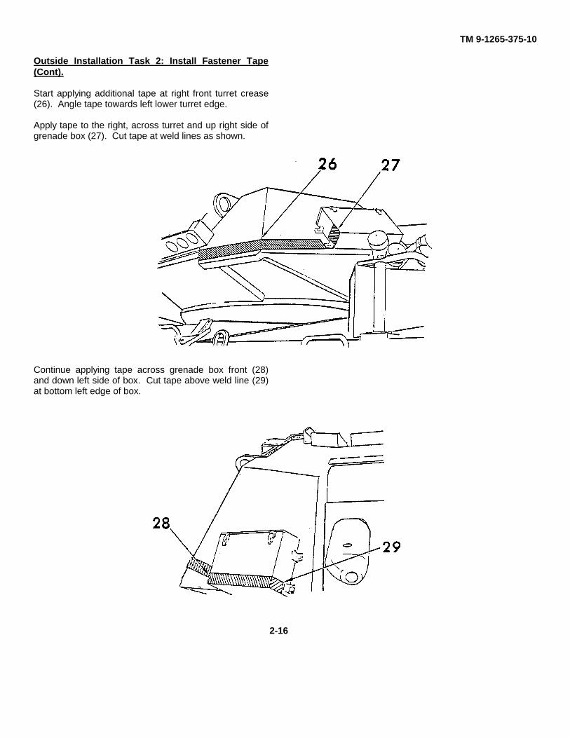


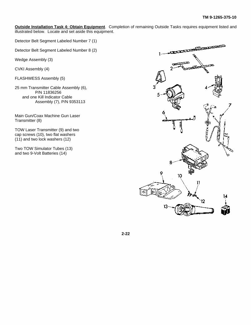


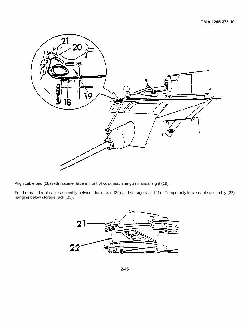


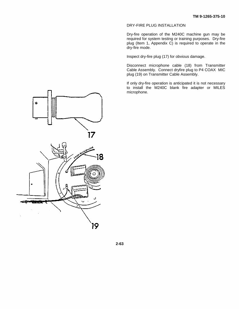


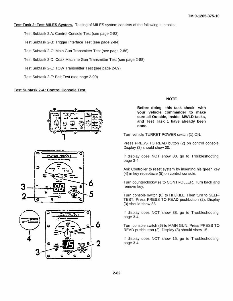
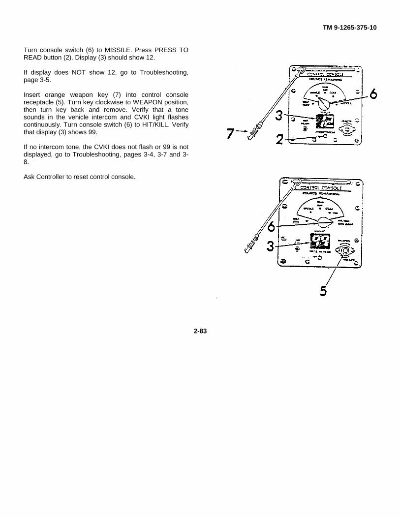


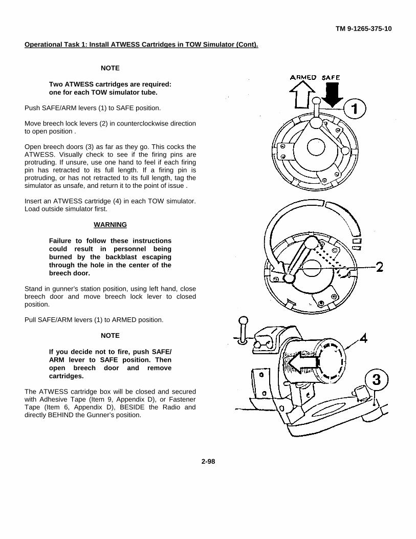


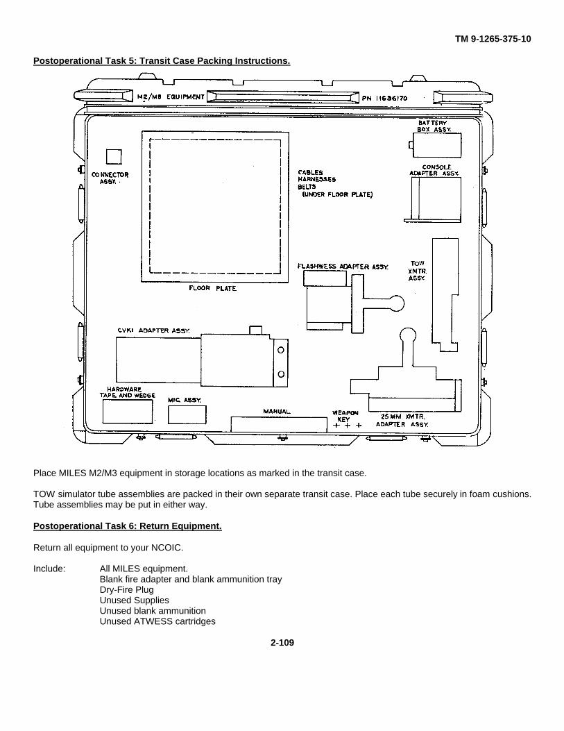


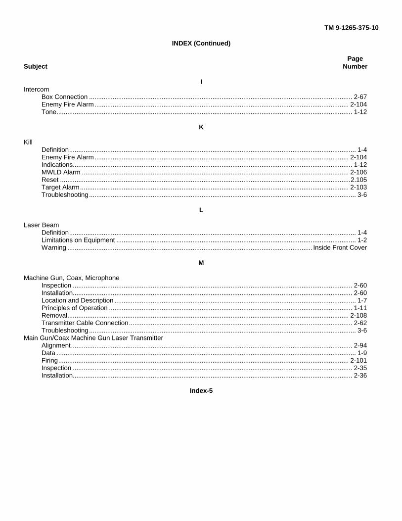


![East-West Highway Maintenance Project (Loan 1265-BHU[SF])](https://static.documents.pub/doc/80x56/577ce66d1a28abf10392ca43/east-west-highway-maintenance-project-loan-1265-bhusf.jpg)


