26
TM-Series Technical Description TM-301 chassis Rev Q, 2009-12-21

TM-Series Technical Description TM-301 chassis Rev Q, 2009-12-21
IN COMMERCIAL CONFIDENCE TECHNICAL DESCRIPTION TM-301 Date: Doc. number: Rev: Page
© Transmode 2009-12-21 TD-TM301 Q 2 (26)
1 GENERAL
The specifications and information within this manual are subject to change without further notice. All statements, information and recommendations are believed to be accurate but are presented without warranty of any kind. Users must take full responsibility for their application of any products.
In no event shall Transmode Systems AB be liable for any indirect, special, consequential or incidental damages, including, without limitation, lost profits or loss or damage to data arising from the use or inability to use this manual, even if Transmode or its suppliers have been advised of the possibility of such damages.
1.1 In commercial confidence
The manual is provided in commercial confidence and shall be treated as such.
1.2 Document Revision History Revision Date Description of changes
A 2004-04-21 First released version
B 2004-10-10 Added information on max power consumption in card cage Added mechanical drawings, noise level values
C 2005-03-18 Restriction: A CU is always required for configurations with 3 Traffic Units.
D 2005-06-30 Transition to new Transmode format. No content change. E 2005-10-31 Clarifications and minor updates of figures F 2005-12-20 Updated with ordering numbers for different slot
configurations G 2006-06-20 Added information on labels
Added information on air filter H 2007-06-29 Cosmetically updates I 2007-08-27 Removal of configurations without CU J 2008-01-18 Updated with new article codes. Text changes to reflect
introduction of CU-SFP K 2008-03-14 Change of logotype L 2008-11-28 Addition of 23” mounting. Enhancements. M 2009-03-10 Addition of chapter 2.3.6
Addition of chapter 4.2.1 Addition of Appendix with configuration examples
N 2009-06-15 Updated tables in section 2.3.6 to reflect release 13.0 content
O 2009-07-10 Addition of max inrush current in Table 6 P 2009-11-30 Introduction of new AC/DC module and configuration without
any half-sized slots Q 2009-12-21 MDU-8 units incorrectly stated not to be supported.
Corrected Table 2
Transmode Systems AB © 2009 Transmode Systems AB Box 42114 All rights reserved. No part of this document SE-126 14 Stockholm may be reproduced without written Home page: www.transmode.com SWEDEN permission of the copyright holder

IN COMMERCIAL CONFIDENCE TECHNICAL DESCRIPTION TM-301 Date: Doc. number: Rev: Page
© Transmode 2009-12-21 TD-TM301 Q 3 (26)
Table of content
1 General...............................................................................................................2 1.1 In commercial confidence ...............................................................................................2 1.2 Document Revision History.............................................................................................2 2 Functional Description........................................................................................4 2.1 Introduction .....................................................................................................................4 2.2 Basic configurations........................................................................................................4 2.3 TM-301 chassis...............................................................................................................5 2.3.1 Fan units .........................................................................................................................6 2.3.2 Air filter............................................................................................................................6 2.3.3 Primary power alternatives..............................................................................................7 2.3.4 External interfaces ..........................................................................................................9 2.3.5 Card Cage.....................................................................................................................10 2.3.6 Plug-in unit data & chassis compatibility .......................................................................12 2.3.7 Chassis Identity.............................................................................................................15 3 Labels ...............................................................................................................16 3.1 Product identifiers .........................................................................................................18 4 Technical data ..................................................................................................19 4.1 Revision data ................................................................................................................20 4.2 Ordering data ................................................................................................................20 4.2.1 Spare parts ...................................................................................................................21 4.3 Mechanical drawings ....................................................................................................22 5 APPENDIX .......................................................................................................24 5.1 TM-301 Configurations .................................................................................................24 5.1.1 Line amplifier configuration ...........................................................................................24 5.1.2 10G Terminal node .......................................................................................................25 5.1.3 Large Terminal node.....................................................................................................26
Transmode Systems AB © 2009 Transmode Systems AB Box 42114 All rights reserved. No part of this document SE-126 14 Stockholm may be reproduced without written Home page: www.transmode.com SWEDEN permission of the copyright holder

IN COMMERCIAL CONFIDENCE TECHNICAL DESCRIPTION TM-301 Date: Doc. number: Rev: Page
© Transmode 2009-12-21 TD-TM301 Q 4 (26)
2 FUNCTIONAL DESCRIPTION
2.1 Introduction
The TM-301 chassis is the medium-sized chassis alternative in the TM-Series. The TM-301 is perfect for smaller collector nodes or to house an intermediate amplifier site.
A Control Unit (CU) is always placed in the first slot. The CU gives an aggregated management view of the chassis. In the standard configuration, two full-sized units can be mounted together with up to four half-sized units.
The TM-301 is provided in AC or DC primary powering options and different mounting options.
For details on installation procedure, see “TM-301 Installation Guide” within the Installation & Commissioning volume of the TM-Series System manual.
2.2 Basic configurations
A Basic TM-301 NE Equipment include • Control Unit (CU-SFP) • Dummy panels • Dual Fan units • Dual DC/DC converters with DC cables • Ethernet cable, DSUB/RJ45 converter, ESD wrist wrap The mounting option adds on • Mounting brackets 19”, ETSI or 23” with screws and nuts The AC power option adds on • Separate AC/DC converters
For configurations where OSC channels are needed, the required amount of SFP’s must be added separately. See “Dimensioning Guidelines” within System Manual for more details.
Figure 1: Basic Equipment TM-301 with CU-SFP
Transmode Systems AB © 2009 Transmode Systems AB Box 42114 All rights reserved. No part of this document SE-126 14 Stockholm may be reproduced without written Home page: www.transmode.com SWEDEN permission of the copyright holder

IN COMMERCIAL CONFIDENCE TECHNICAL DESCRIPTION TM-301 Date: Doc. number: Rev: Page
© Transmode 2009-12-21 TD-TM301 Q 5 (26)
2.3 TM-301 chassis
The TM-301 chassis can be divided into four parts:
• Fan area • Card cage • Power and external interfaces • Fiber management area
Figure 2: The main parts of a TM-301 NE Platform
The Fan and Power and external interface modules are screwed to the mechanics but still easy to extract via handles.
Different mounting brackets are used when mounting the TM-301 into an ETSI, 19” or a 23” building practice.
Fiber slack can be handled via the fiber management area. A separate fiber management shelf is recommended for configurations with plug-in units having multiple client ports.
Transmode Systems AB © 2009 Transmode Systems AB Box 42114 All rights reserved. No part of this document SE-126 14 Stockholm may be reproduced without written Home page: www.transmode.com SWEDEN permission of the copyright holder

IN COMMERCIAL CONFIDENCE TECHNICAL DESCRIPTION TM-301 Date: Doc. number: Rev: Page
© Transmode 2009-12-21 TD-TM301 Q 6 (26)
2.3.1 Fan units
On the left a fan unit module is placed. It can easily be extracted and replaced by pulling the module outwards using the handle.
Figure 3: Cooling of TM-301
The fan module contains two fan units. If one fan unit fails the red LED on the cover panel will ignite and an alarm will be generated to the Control Unit. The other FAN unit has the capacity to cool the system alone. A hot-swap of the failed unit can be done.
On the far right side a mechanical air filter is placed. It can be extracted for replacement. The airflow is shown in Figure 3.
2.3.2 Air filter
An air filter is placed on the far right hand side of the card cage. This filter should be extracted and cleaned every second year under normal conditions. See System Manual “Operation & Maintenance”, “Spare Part & Maintenance Guide” for more details.
Transmode Systems AB © 2009 Transmode Systems AB Box 42114 All rights reserved. No part of this document SE-126 14 Stockholm may be reproduced without written Home page: www.transmode.com SWEDEN permission of the copyright holder

IN COMMERCIAL CONFIDENCE TECHNICAL DESCRIPTION TM-301 Date: Doc. number: Rev: Page
© Transmode 2009-12-21 TD-TM301 Q 7 (26)
2.3.3 Primary power alternatives
On the right side, two slots are available for primary power configurations.
AC-power
An AC powered configuration is shown in Figure 4. The AC/DC conversion is done in an external unit and connected to one of the DC inlet modules. Two DC input modules are provided to allow for A & B power configurations. The AC voltage accepted is either 115 or 230V.
Figure 4: AC power configuration
A green LED indicator (PWR) is placed on the front of the module to indicate a functioning unit. Upon failure, the LED will be turned off and an alarm will be generated to the management system. A hot-swap replacement of the failed module can be done.
The red LED (POL ERR) indicates polarity error, i.e. the – 48 voltage has been wrongly connected. This is only a visual indication and will not generate any alarm to the management system.
The AC/DC unit has a green LED indicator to indicate correct function.
Transmode Systems AB © 2009 Transmode Systems AB Box 42114 All rights reserved. No part of this document SE-126 14 Stockholm may be reproduced without written Home page: www.transmode.com SWEDEN permission of the copyright holder

IN COMMERCIAL CONFIDENCE TECHNICAL DESCRIPTION TM-301 Date: Doc. number: Rev: Page
© Transmode 2009-12-21 TD-TM301 Q 8 (26)
DC-power
External -48V DC power is here connected directly to the DC power inlet modules. The two modules are used to enable A & B power configurations. Both 2-wire and 3-wire configurations are possible.
Figure 5: DC power configuration
A green LED indicator (PWR) is placed on the front of the module to indicate a functioning unit. Upon failure, the LED will be turned off and an alarm will be generated to the management system. A hot-swap replacement of the failed module can be done.
The red LED (POL ERR) indicates polarity error, i.e. the – 48 voltage has been wrongly connected. This is only a visual indication and will not generate any alarm to the management system.
Note! The same product (TM-301-DDC/19, /ETSI with R-state R1B) is used for both AC and DC powering. In the AC configuration external AC/DC units are added and connected to the DC inlet connectors. In the DC-configuration, the DC voltage is connected directly.
The previous R-state R1A had a special DC-inlet module.
Fuse 3,15A
Transmode Systems AB © 2009 Transmode Systems AB Box 42114 All rights reserved. No part of this document SE-126 14 Stockholm may be reproduced without written Home page: www.transmode.com SWEDEN permission of the copyright holder

IN COMMERCIAL CONFIDENCE TECHNICAL DESCRIPTION TM-301 Date: Doc. number: Rev: Page
© Transmode 2009-12-21 TD-TM301 Q 9 (26)
2.3.4 External interfaces
To the far right a LAN module is situated for electrical connections.
Figure 6: LAN module
Three RJ-45 connector types are available for the following applications:
• DCN 1 – Management interface to the Network Element. A LAN-connection via Ethernet interface (10Mb/s or 100Mb/s) that can be connected directly to a Transmode Network Manager (TNM) platform or via a DCN network.
• ICN 3 & ICN 4 – Internal Communication Network, used when connecting multiple TM-301 platforms to create a larger NE. See Installation & Commissioning manual for further details.
The electrical Ethernet interfaces can be connected to its interfacing equipment with an Ethernet cable and is suitable for connection to intra-building wiring only. The maximum allowed physical length of the cable is 100 m, provided that a Cat 5e class shielded cable is used and the shield is grounded at both ends. Unshielded cable usage is not warranted by Transmode and such usage is discouraged.
equipment with an Ethernet cable and is suitable for connection to intra-building wiring only. The maximum allowed physical length of the cable is 100 m, provided that a Cat 5e class shielded cable is used and the shield is grounded at both ends. Unshielded cable usage is not warranted by Transmode and such usage is discouraged.
Transmode Systems AB © 2009 Transmode Systems AB Box 42114 All rights reserved. No part of this document SE-126 14 Stockholm may be reproduced without written Home page: www.transmode.com SWEDEN permission of the copyright holder

IN COMMERCIAL CONFIDENCE TECHNICAL DESCRIPTION TM-301 Date: Doc. number: Rev: Page
© Transmode 2009-12-21 TD-TM301 Q 10 (26)
2.3.5 Card Cage
Figure 7: TM-301 card cage area
The card cage has one dedicated slot (slot 1) for a Control Unit (CU). The two following slots (2 & 3) are for full-height Traffic Units.
Slots 4 to 7 are in the standard configuration used for four half-sized units, i.e. typically passive units.
The wall between slots 4-5 and 6-7 can be reduced to provide one or two additional full-sized slots. This is reconfiguration that has to be done in production and consequently these configurations are ordered via separate ordering numbers (see chapter 4.2).
Figure 8: Slot usage in standard configuration TM301xxyy/2
In the standard configuration TM301xxyy/2 the TM-301 can be equipped with up to two active units (Transponders, Muxponders, Optical Amplifiers) and four half-height units.
Transmode Systems AB © 2009 Transmode Systems AB Box 42114 All rights reserved. No part of this document SE-126 14 Stockholm may be reproduced without written Home page: www.transmode.com SWEDEN permission of the copyright holder

IN COMMERCIAL CONFIDENCE TECHNICAL DESCRIPTION TM-301 Date: Doc. number: Rev: Page
© Transmode 2009-12-21 TD-TM301 Q 11 (26)
Figure 9: Slot usage in special configuration TM301xxyy/1
In the special configuration TM301xxyy/1 the TM-301 can be equipped with up to three active units (Transponders, Muxponders, Optical Amplifiers) and two half-height units.
Figure 10: Slot usage in special configuration TM301xxyy/0
In the special configuration TM301xxyy/0 the TM-301 can be equipped with up to three active units (Transponders, Muxponders, Optical Amplifiers) and one passive full-height unit.
Note! In the TM301xxyy/0 configuration the bottom slot 5 must only be equipped with passive units since the air flow from the fan unit is not sufficient for an active unit. In the TM301xxyy/0 configuration the slot 5 can be used for e.g. a MDU8EE919-926 unit.
Note: In the special configurations TM301xxyy/1 and TM301xxyy/0 where three Traffic Units can be inserted, there are power dissipation restrictions that may prohibit some combinations of high-power units. Always verify that the power consumption is within the limits.
In DC-powering the max power dissipation within the card cage is 120W. In AC-powering the max power dissipation is dependent on used AC/DC converter: - PS1A-120/DS3 restricts the power within the card cage to 101W. - PS1A-180/DS3 provides same power within the card cage as for DC, i.e. 120W.
PS1A-180/DS3 was introduced in Dec 2009 and shipment of TM-301 in AC configuration is done with PS1A-180/DS3 from that point in time.
A CU-SFP with OSC transceivers will consume 20W of the above values. A CU-SFP without OSC transceivers will consume 18W of the above values.
Transmode Systems AB © 2009 Transmode Systems AB Box 42114 All rights reserved. No part of this document SE-126 14 Stockholm may be reproduced without written Home page: www.transmode.com SWEDEN permission of the copyright holder

IN COMMERCIAL CONFIDENCE TECHNICAL DESCRIPTION TM-301 Date: Doc. number: Rev: Page
© Transmode 2009-12-21 TD-TM301 Q 12 (26)
2.3.6 Plug-in unit data & chassis compatibility
The below tables lists all plug-in units available at release 12.0. For each plug-in unit a “Type” parameters is defined; “Type” has four parameters; “A” = Active unit, i.e. must be inserted in an active slot
“P” = Passive unit, i.e. must be inserted in an active slot “FH” = Full-height unit, i.e. occupies a full-height slot “HH” = Half-height unit, i.e. occupies a half-height slot
Every unit is a combination of Active/Passive and Full-height/Half-height.
As an example: The TPQMR has the type “A/FH” meaning that the unit shall be inserted in an active, full-height slot.
Table 1: Plug-in unit data and chassis compatibility (Release 14.0 content)
Category Item Name Item ID Type Slot width
TM- 3000
TM-301
TM-101
TM-102
MultiRate 2500 DWDM Transponder V2 TPMR25-V2/xxxxx A/FH 1 Y Y Y Y Quad MultiRate xWDM Transponder TPQMR A/FH 1 Y Y Y Y Double DGbE xWDM, Basic Unit TPDDGBE A/FH 1 Y Y Y Y 10-port GFP xWDM Muxponder GXP10/2500-SFP A/FH 1 Y Y Y Y
Transponders Muxponders
@ 2.5G line rate
8-port SDH xWDM Muxponder MXP8 A/FH 1 Y Y Y Y MultiService Muxponder MS-MXP A/FH 1 Y Y Y Y @
4G line rate Quad MultiService Transponder TPQMS A/FH 1 Y Y Y Y Double 10Gb/s Lite Basic Unit TPD10G-L-BU A/FH 1 Y Y Y Y 10Gb/s Transponder, Client-XFP, BU TP10GCLX/xxxxx A/FH 1 Y Y Y Y 10Gb/s C-band Tunable Transp TP10GCLX/TC A/FH 1 Y Y Y Y 10Gb/s C-band Tunable Ext Reach TP10G/TC-ER A/FH 1 Y Y Y Y 10G C-band Tunable OTN Transponder TP10GOTN/TC A/FH 1 Y Y Y Y 9xGbE/10Gb Muxponder, BU GBE9-MXP10G A/FH 1 Y Y Y Y 9xGbE/10G FEC Muxponder GBE9/MXP10GFEC A/FH 1 Y Y Y Y Double 10Gb/s FEC Basic Unit TPD10GBE-BU A/FH 1 Y Y N Y 4xSTM-16/STM-64 Muxponder 4x2G5-MXP10G A/FH 1 Y Y Y Y MultiService MuxPonder 10G MS-MXP/10G A/FH 1 Y Y Y Y
@ 10G line rate
MultiService MXP Tunable 10G ER MS-MXP10G/TC-ER A/FH 1 Y Y N N 6-port GbE Ethernet Demarcation Unit EDU/6PGBE A/FH 1 Y Y Y Y 10xGbE/10GbE Ethernet Muxponder GBE10-EMXP10 A/FH 1 Y Y Y Y 22xGbE/10GbE Ethernet Muxponder GBE22-EMXP10 A/FH 2 Y Y N N Layer-2
12-port GbE Ethernet Demarcation Unit EDU/12PGBE A/FH 1 Y Y Y Y
Type A = Active unit, i.e. must be inserted in an active slot Type P = Passive unit, i.e. must be inserted in an active slot Type FH = Full-height unit, i.e. occupies a full-height slot
Type HH = Half-height unit, i.e. occupies a half-height slot
Transmode Systems AB © 2009 Transmode Systems AB Box 42114 All rights reserved. No part of this document SE-126 14 Stockholm may be reproduced without written Home page: www.transmode.com SWEDEN permission of the copyright holder

IN COMMERCIAL CONFIDENCE TECHNICAL DESCRIPTION TM-301 Date: Doc. number: Rev: Page
© Transmode 2009-12-21 TD-TM301 Q 13 (26)
Table 2: Plug-in unit data and chassis compatibility (Release 14.0 content) , cont.
Category Item Name Item ID Type Slot width
TM- 3000
TM-301
TM-101
TM-102
1ch DWDM Add-Drop Unit, AB-version 1ch DWDM Add-Drop Unit, BA-version
AD1AB/xxxxx AD1BA/xxxxx P/HH 1 Y Y Y Y
2ch DWDM Add-Drop Unit, AB-version 2ch DWDM Add-Drop Unit, BA-version
AD2AB/xxxxx AD2BA/xxxxx P/HH 1 Y Y Y Y
4ch DWDM Add-Drop Unit, AB-version 4ch DWDM Add-Drop Unit, BA-version
AD4AB/xxxxx AD4BA/xxxxx P/HH 1 Y Y Y Y
2ch OA DWDM Add-Drop Unit AB 2ch OA DWDM Add-Drop Unit BA
AD2OAAB/xxxxx AD2OABA/xxxxx P/HH 1 Y Y Y Y
1ch/2F A/D DWDM Add-Drop AD1-2F/xxxxx P/HH 1 Y Y Y Y 4ch/2-fiber DWDM Add-Drop AD4-2F/xxxxx P/HH 1 Y Y Y Y
DWDM Optical
Add/drop
1x4 ROADM 100GHz 1x4ROADM/100G A/FH 2 Y N N N 8ch Mux/DeMux, Extendable MDU8-E P/FH 1 Y Y N N 8ch Mux/DeMux, Terminal MDU8-T P/FH 1 Y Y N N 8ch Even Mux/DeMux, Extendable MDU8-E/EVEN-C P/FH 1 Y Y N N 8ch Even Mux/DeMux, Terminal MDU8-T/EVEN-C P/FH 1 Y Y N N 40ch MDU, even 50GHz DWDM MDU40/50G-EVEN A/FH 3 Y N N N 40ch MDU, odd 50GHz DWDM MDU40/50G-ODD A/FH 3 Y N N N MDU-E 8ch Even 50GHz DWDM MDU8EE919-926 P/FH 1 Y Y N N MDU-E 8ch Even 50GHz DWDM MDU8EE927-934 P/FH 1 Y Y N N MDU-E 8ch Even 50GHz DWDM MDU8EE935-942 P/FH 1 Y Y N N MDU-E 8ch Even 50GHz DWDM MDU8EE943-950 P/FH 1 Y Y N N MDU-E 8ch Even 50GHz DWDM MDU8EE951-958 P/FH 1 Y Y N N MDU-E 8ch Odd 50GHz DWDM MDU8EO9185-9255 P/FH 1 Y Y N N MDU-E 8ch Odd 50GHz DWDM MDU8EO9265-9335 P/FH 1 Y Y N N MDU-E 8ch Odd 50GHz DWDM MDU8EO9345-9415 P/FH 1 Y Y N N MDU-E 8ch Odd 50GHz DWDM MDU8EO9425-9495 P/FH 1 Y Y N N
DWDM Optical
Mux/DeMux
MDU-E 8ch Odd 50GHz DWDM MDU8EO9505-9575 P/FH 1 Y Y N N Optical Interleaver Unit 100/200GHz OIU-C-100/200 P/HH 1 Y Y Y Y Optical Interleaver Unit 50/100GHz OIU-C-50/100 P/HH 1 Y Y Y Y 8ch Variable Optical Attenuator unit VOA-8CH P/FH 1 Y Y N N 2-port OCM OCM/2p A/FH 1 Y Y N N 8ch Variable Optical Attenuator – II VOA-8CH/II A/FH 1 Y Y N N
Misc DWDM
2ch Variable Optical Attenuator VOA-2CH A/HH 1 Y Y Y Y
Table 3: Plug–in unit data and chassis compatibility (Release 14.0 content), cont.
Category Item Name Item ID Type Slot width
TM- 3000
TM-301
TM-101
TM-102
Optical Line Amplifier 17dBm C-band OA17C A/FH 1 Y Y Y Y Dual Optical Line Amplifier 17/17dBm C-band OA2-17/17CC A/FH 1 Y Y Y Y
Optical Line Amplifier 20dBm C-band OA20C A/FH 1 Y Y Y Y Dual Optical Line Amplifier 20/20dBm C-band OA2-20/20CC A/FH 1 Y Y Y Y
Opt Low Gain Amp C-Band 20dBm OA20C/LG A/FH 1 Y Y Y Y Dual Opt Low Gain Amp C-Band 20dBm OA2-20/20/CC/LG A/FH 1 Y Y Y Y
Optical Amplifiers
Opt Flat Gain Amp C-Band 10 dBm OA10C/FG A/FH 1 Y Y Y Y
Type A = Active unit, i.e. must be inserted in an active slot Type P = Passive unit, i.e. must be inserted in an active slot Type FH = Full-height unit, i.e. occupies a full-height slot
Type HH = Half-height unit, i.e. occupies a half-height slot
Transmode Systems AB © 2009 Transmode Systems AB Box 42114 All rights reserved. No part of this document SE-126 14 Stockholm may be reproduced without written Home page: www.transmode.com SWEDEN permission of the copyright holder

IN COMMERCIAL CONFIDENCE TECHNICAL DESCRIPTION TM-301 Date: Doc. number: Rev: Page
© Transmode 2009-12-21 TD-TM301 Q 14 (26)
Table 4:Plug-in unit data and chassis compatibility (Release 14.0 content) , cont.
Category Item Name Item ID Type Slot width
TM- 3000
TM- 301
TM- 101
TM- 102
Optical Band Unit OBU1300/1550 P/HH 1 Y Y Y Y 2xOptical Coupler Unit OCU2 P/HH 1 Y Y Y Y Misc passive
units 4xOptical Coupler Unit OCU4 P/HH 1 Y Y Y Y
Active unit Protection Control Unit PCU/2P A/HH 1 Y N N N
Table 5: Plug-in unit data and chassis compatibility (Release 14.0 content) , cont.
Category Item Name Item ID Type Slot width
TM- 3000
TM- 301
TM- 101
TM- 102
1ch Add/drop CWDM1) (single-fiber) ADCWDM/yyyy P/HH 1 Y Y Y Y
1ch CWDM Add/drop (single-fiber) AD1C/yyyy P/HH 1 Y Y Y Y 2x1ch Add/Drop CWDM (single-fiber) AD2X1C/yyyy P/HH 1 Y Y Y Y
CWDM AD-filters
1ch/2-fiber CWDM Add-Drop 2) AD1C-2F/yyyy P/HH 1 Y Y Y Y 4ch MDU CWDM, single fiber, TA 4ch MDU CWDM, single fiber, TB
MDUC4-TA/1470 MDUC4-TB/1470 P/HH 1 Y Y Y Y
4ch MDU CWDM, single fiber, EA 4ch MDU CWDM, single fiber, EB
MDUC4-EA/1270 MDUC4-EB/1270 P/HH 1 Y Y Y Y
8ch CWDM Mux, fiber-pair 8ch CWDM DeMux, fiber-pair
MU-2F/1470 DU-2F/1470 P/HH 1 Y Y Y Y
4ch CWDM MDU fiber-pair Extendable MDU4-E-2F P/HH 1 Y Y Y Y
CWDM Optical
Mux/DeMux
4ch CWDM MDU fiber-pair Terminal MDU4-T-2F P/HH 1 Y Y Y Y
Type A = Active unit, i.e. must be inserted in an active slot Type P = Passive unit, i.e. must be inserted in an active slot Type FH = Full-height unit, i.e. occupies a full-height slot
Type HH = Half-height unit, i.e. occupies a half-height slot
Transmode Systems AB © 2009 Transmode Systems AB Box 42114 All rights reserved. No part of this document SE-126 14 Stockholm may be reproduced without written Home page: www.transmode.com SWEDEN permission of the copyright holder
IN COMMERCIAL CONFIDENCE TECHNICAL DESCRIPTION TM-301 Date: Doc. number: Rev: Page
© Transmode 2009-12-21 TD-TM301 Q 15 (26)
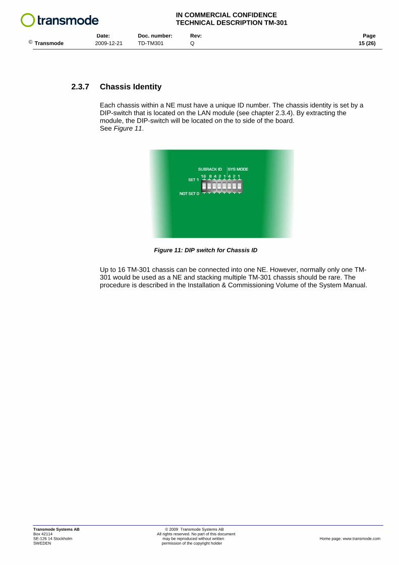
2.3.7 Chassis Identity
Each chassis within a NE must have a unique ID number. The chassis identity is set by a DIP-switch that is located on the LAN module (see chapter 2.3.4). By extracting the module, the DIP-switch will be located on the to side of the board. See Figure 11.
Figure 11: DIP switch for Chassis ID
Up to 16 TM-301 chassis can be connected into one NE. However, normally only one TM-301 would be used as a NE and stacking multiple TM-301 chassis should be rare. The procedure is described in the Installation & Commissioning Volume of the System Manual.
Transmode Systems AB © 2009 Transmode Systems AB Box 42114 All rights reserved. No part of this document SE-126 14 Stockholm may be reproduced without written Home page: www.transmode.com SWEDEN permission of the copyright holder

IN COMMERCIAL CONFIDENCE TECHNICAL DESCRIPTION TM-301 Date: Doc. number: Rev: Page
© Transmode 2009-12-21 TD-TM301 Q 16 (26)
3 LABELS
The TM-301 chassis is marked with a Product Label and a System Label. Both are placed on the top of the chassis, on the left, front side.
The Product label contains:
1. Transmode logotype 2. Product number 3. Product revision 4. Barcode 128 containing: product number “space” revision 5. Production date: yearWweeknumber 6. Serial number 7. Barcode 128 containing: serial number 8. Barcode 128 containing: product number, revision, production date, serial number 9. Approval markings
8
7
4
Transmode Systems AB © 2009 Transmode Systems AB Box 42114 All rights reserved. No part of this document SE-126 14 Stockholm may be reproduced without written Home page: www.transmode.com SWEDEN permission of the copyright holder

IN COMMERCIAL CONFIDENCE TECHNICAL DESCRIPTION TM-301 Date: Doc. number: Rev: Page
© Transmode 2009-12-21 TD-TM301 Q 17 (26)
The System Label contains: 1. Transmode logotype 2. System type 3. Production date: yearWweeknumber 4. Ratings 5. Laser class, 6. Compliance info, 7. Approval markings
Transmode Systems AB © 2009 Transmode Systems AB Box 42114 All rights reserved. No part of this document SE-126 14 Stockholm may be reproduced without written Home page: www.transmode.com SWEDEN permission of the copyright holder

IN COMMERCIAL CONFIDENCE TECHNICAL DESCRIPTION TM-301 Date: Doc. number: Rev: Page
© Transmode 2009-12-21 TD-TM301 Q 18 (26)
3.1 Product identifiers
Figure 12: Product labels
All exchangeable modules on the Basic NE Equipment are labeled. The figure shows labeling of
• Fan unit • LAN module • DC-inlet module • TM-301 Chassis
The label contains the following information:
• Product number • R-state • Serial number • Bar code with the above information
The above information on these specific modules is not accessible via the inventory function in the management system. Inventory data on CU’s and Traffic Units are available via the inventory functionality.
Transmode Systems AB © 2009 Transmode Systems AB Box 42114 All rights reserved. No part of this document SE-126 14 Stockholm may be reproduced without written Home page: www.transmode.com SWEDEN permission of the copyright holder

IN COMMERCIAL CONFIDENCE TECHNICAL DESCRIPTION TM-301 Date: Doc. number: Rev: Page
© Transmode 2009-12-21 TD-TM301 Q 19 (26)
4 TECHNICAL DATA Table 6: Mechanical & electrical data
TM-301 Height 3U / 133mm Depth 280mm / 11” Width (excl. mounting brackets) 445mm/17.5” Primary Power DC-inlets. Redundant, Hot-swap
Cooling Redundant fans. Hot-swap
Mounting ETSI, 19”, 23” Fiber management Yes LAN/Mgmt connections RJ45
Primary power range, AC: External AC/DC-converter 100-240VAC, 50/60Hz, 2.5A Class I.
Size AC/DC converter
PS1A-120/DS3 excl connectors. Length: 180mm Width: 95mm Height: 50mm
Primary power range DC: 48VDC (40.8 – 57.6VDC), 5A Class III Max power at AC powering 160 W Max power at DC powering 150 W
Max power consumption in card cage (incl CU-SFP)
~120W in DC powering ~101W in AC powering using PS1A-120/DS3 ~120W in AC powering using PS1A-180/DS3
Max Inrush current @ -48VDC 4,0A / 4ms
Weight DC-powering: 7,5 kg (mechanics + fan unit + 2x DC TM-301(DC) + LAN module
DC cable size 1,5mm2
(connector limit) Standard 1,0mm2
Table 7: Capacity
TM-301 Number of full-sized slots1) Up to 3 Number of half-sized slots2) Up to 4 No of λ in largest possible configuration3)
8 CWDM or 3 DWDM
No of λ in smallest possible configuration4)
1 CWDM or DWDM wavelength
(via 1ch add/drop)
1) Slots for Traffic units (Transponders/MuxPonders) 2) Slots for passive units (Add/drop filters, MDU’s) 3) Includes both Traffic units and passive unit within same chassis, i.e. a fully configured NE 4) Using Transponder and optical unit with lowest granularity
Note: The TM-301 chassis can mechanically be configured for 2x “full-slots” + 4x “half-slots” or 3x “full-slots” + 2x “half-slots”
Transmode Systems AB © 2009 Transmode Systems AB Box 42114 All rights reserved. No part of this document SE-126 14 Stockholm may be reproduced without written Home page: www.transmode.com SWEDEN permission of the copyright holder

IN COMMERCIAL CONFIDENCE TECHNICAL DESCRIPTION TM-301 Date: Doc. number: Rev: Page
© Transmode 2009-12-21 TD-TM301 Q 20 (26)
4.1 Revision data
A TM-301 chassis has an order level that includes mechanics, cables, Control Unit etc as listed in chapter 4.2. The table shows revision data on “M301/ENC” which is the basic card cage mechanics. Changes in this basic mechanics is reflected on the M301/ENC level
Table 8: Revision data
Product number Rev Introduced Release
R1A A2.2 1st released version M301/ENC
R1B A2.3.2
4.2 Ordering data Table 9: Configuration alternatives Basic NE-Equipment TM-301
Configuration Ordering code Comments TM-301, DC, 19” Shelf=2 TM301DC19/2 Standard config. TM-301, AC, 19”, Shelf=2 TM301AC19/2 Standard config. TM-301, DC, ETSI Shelf=2 TM301DCET/2 Standard config. TM-301, AC, ETSI, Shelf=2 TM301ACET/2 Standard config. TM-301, DC, 23” Shelf=2 TM301DC23/2 Standard config. TM-301, AC, 23”, Shelf=2 TM301AC23/2 Standard config. TM-301, DC, 19” Shelf=1 TM301DC19/1 Special config. TM-301, AC, 19”, Shelf=1 TM301AC19/1 Special config. TM-301, DC, ETSI Shelf=1 TM301DCET/1 Special config. TM-301, AC, ETSI, Shelf=1 TM301ACET/1 Special config. TM-301, DC, 23” Shelf=1 TM301DC23/1 Special config. TM-301, AC, 23”, Shelf=1 TM301AC23/1 Special config. TM-301, DC, 19” Shelf=0 TM301DC19/0 Special config. TM-301, AC, 19”, Shelf=0 TM301AC19/0 Special config. TM-301, DC, ETSI Shelf=0 TM301DCET/0 Special config. TM-301, AC, ETSI, Shelf=0 TM301ACET/0 Special config. TM-301, DC, 23” Shelf=0 TM301DC23/0 Special config. TM-301, AC, 23”, Shelf=0 TM301AC23/0 Special config.
When OSC channels are required, SFP’s must be added to the above ordering numbers. See “Dimensioning Guidelines” within the System Manual for more details.
Transmode Systems AB © 2009 Transmode Systems AB Box 42114 All rights reserved. No part of this document SE-126 14 Stockholm may be reproduced without written Home page: www.transmode.com SWEDEN permission of the copyright holder

IN COMMERCIAL CONFIDENCE TECHNICAL DESCRIPTION TM-301 Date: Doc. number: Rev: Page
© Transmode 2009-12-21 TD-TM301 Q 21 (26)
The above ordering numbers include the following items: • TM-301 card cage • Control Unit CU-SFP (1 per chassis) • DC/DC filter module (2 items per chassis) • External AC/DC converter 115/230V 120W (2 per chassis, only for AC configuration) • LAN module / RJ 45 card (1 per chassis) • Dummy panels, full-sized (2 items) • Dummy panels, half-sized (4 items) • DC cable, 4m (2 items) • Ethernet cable, 2m (1 item) • DSUB adapter RJ45/DB9 (1 item) • ESD wrist wrap with strap (1 item) • Mounting material in rack; nuts, plastic plates, screws (4 sets) • Mounting brackets 19” (mounted, 2 per chassis) • Mounting brackets ETSI (2 per chassis, only in ETSI version) • Mounting brackets 23” (2 per chassis, only in 23”version)
4.2.1 Spare parts The TM-301 chassis has the following spare part items:
Table 10: Spare parts
Item name Item code Comment Fan unit TM-301 M301-FAN One module used per chassis DC power plugin module -48V M301-DC Two modules used per chassis LAN module TM-301 M301-RJ45 One per chassis
AC/DC converter (external) PS1A-120/DS3 Two per chassis (replaced by PS1A-180/DS3)
M301 ACDC Unit (180W) PS1A-180/DS3 Two per chassis Dummy panel 6HE inkl ovl o EMC-list M3-DU/6HE Full-height slot cover panel Dummy panel 3HE inkl ovl o EMC-list M3-DU/3HE Half-height slot cover panel M301 airfilter M9-M301/AIR One per chassis
Transmode Systems AB © 2009 Transmode Systems AB Box 42114 All rights reserved. No part of this document SE-126 14 Stockholm may be reproduced without written Home page: www.transmode.com SWEDEN permission of the copyright holder

IN COMMERCIAL CONFIDENCE TECHNICAL DESCRIPTION TM-301 Date: Doc. number: Rev: Page
© Transmode 2009-12-21 TD-TM301 Q 22 (26)
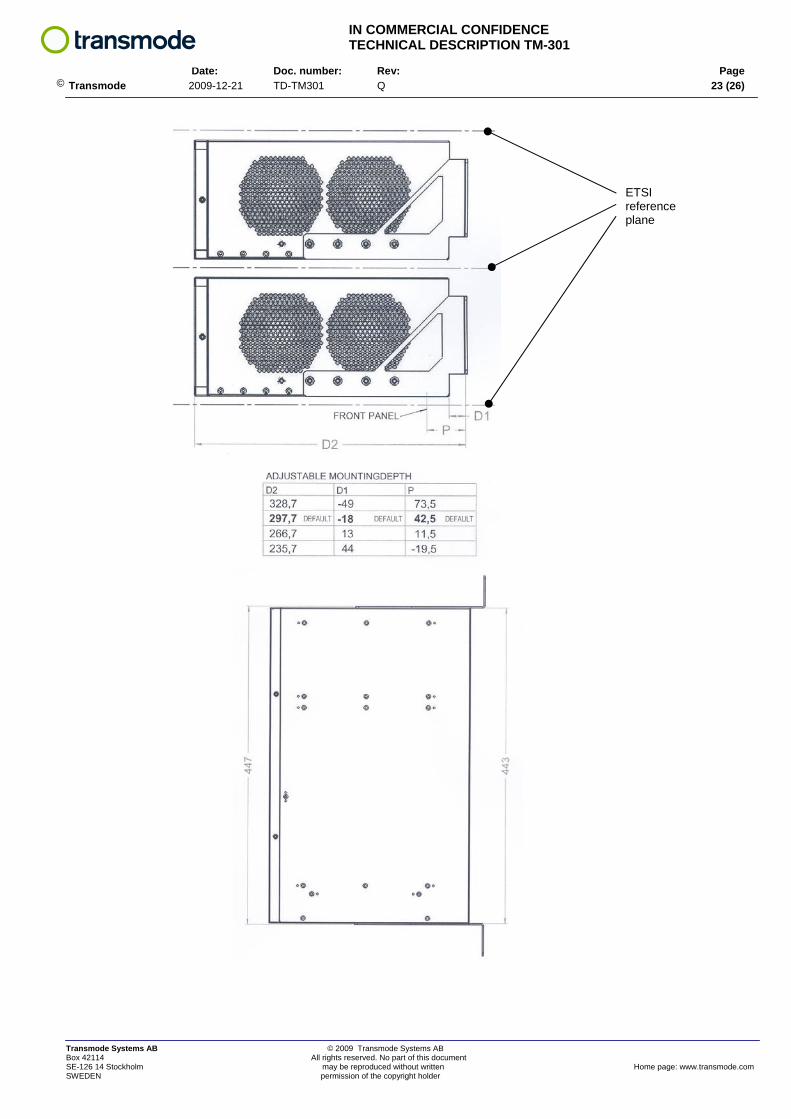
4.3 Mechanical drawings
ETSI reference plane
Transmode Systems AB © 2009 Transmode Systems AB Box 42114 All rights reserved. No part of this document SE-126 14 Stockholm may be reproduced without written Home page: www.transmode.com SWEDEN permission of the copyright holder
IN COMMERCIAL CONFIDENCE TECHNICAL DESCRIPTION TM-301 Date: Doc. number: Rev: Page
© Transmode 2009-12-21 TD-TM301 Q 23 (26)
ETSI reference plane
Transmode Systems AB © 2009 Transmode Systems AB Box 42114 All rights reserved. No part of this document SE-126 14 Stockholm may be reproduced without written Home page: www.transmode.com SWEDEN permission of the copyright holder

IN COMMERCIAL CONFIDENCE TECHNICAL DESCRIPTION TM-301 Date: Doc. number: Rev: Page
© Transmode 2009-12-21 TD-TM301 Q 24 (26)
5 APPENDIX
5.1 TM-301 Configurations
5.1.1 Line amplifier configuration
Figure 13: Line amplifier NE with OSC channels
20 W
27 W
47 W total
CU-SFP (with SFP's for OSC channels)
Double OA20
Not used
OSC AD-filter OSC AD-filter
Not used Not used
Figure 14: Board placement and power consumption
Transmode Systems AB © 2009 Transmode Systems AB Box 42114 All rights reserved. No part of this document SE-126 14 Stockholm may be reproduced without written Home page: www.transmode.com SWEDEN permission of the copyright holder

IN COMMERCIAL CONFIDENCE TECHNICAL DESCRIPTION TM-301 Date: Doc. number: Rev: Page
© Transmode 2009-12-21 TD-TM301 Q 25 (26)
5.1.2 10G Terminal node
Figure 15: 4x10G Terminal NE using TPD10G-BU
18 W
43 W
43 W
104 W total
CU-SFP (w/o SFP's for OSC channels)
TPD10GBE-BU
TPD10GBE-BU
4ch MDU-E 2F Not used
Not used Not used
Figure 16: Board placement and power consumption
Transmode Systems AB © 2009 Transmode Systems AB Box 42114 All rights reserved. No part of this document SE-126 14 Stockholm may be reproduced without written Home page: www.transmode.com SWEDEN permission of the copyright holder

IN COMMERCIAL CONFIDENCE TECHNICAL DESCRIPTION TM-301 Date: Doc. number: Rev: Page
© Transmode 2009-12-21 TD-TM301 Q 26 (26)
Transmode Systems AB © 2009 Transmode Systems AB Box 42114 All rights reserved. No part of this document SE-126 14 Stockholm may be reproduced without written Home page: www.transmode.com SWEDEN permission of the copyright holder
5.1.3 Large Terminal node
Figure 17: 4x10G Terminal NE using mix of units
This configuration uses the special TM-301 configuration enabling three full-sized slots and two half-sized slots.
18 W
32 W
20 W
25 W
95 W total
MDUC4-TA/1470 MDUC4-TB/1470
TPDDGBE
CU-SFP (w/o SFP's for OSC channels)
GBE9/MXP10GFEC
MS-MXP
Figure 18: Board placement and power consumption


