+ All Categories
Home > Documents > TM9_731G_1943

TM9_731G_1943

Date post: 14-Apr-2018
Category:
Upload: jdnwotc
View: 214 times
Download: 0 times
Share this document with a friend
285
53 ADVA NCE COP Y FO R  US E IN ORDNA NCE OFF ICE ONLY. REGULAR  DISTRIBUTI ON WILL BE MADE  BY YOUR LO C AL ADJU TANT GE NERAL OR POST A DJU TANT. TM  9- 731G  o rH S WA R D E P A R T M E N T T E C HNICAL   M A N U A L  3 - INCH  G U N M OTOR C A R R I A G E M1 0 A 1 s e 2 8  JU LY 1943 rf*- E OF F IC E U S E O NL Y  if Disse mina tion of restrict ed  matter . The in formatio n contai n ed in re CO stric ted d ocuments a nd the  essen tial charact eristics of restr icte d m ateriel may be g iven to any pers on know n to be in the service o f the United Sta tes and t o person s of und oubte d loyalty an d discretion who  are cooperating in Gover nm ent wo rk, but w ill not be commu nicated to the pu b lic or to the p res s O except b y authorized m il itary public relat ion s agencies. (S e e also paragra ph 18 b, A R  3 80-5, 28 Septe mber 1942.) !?:\ AR M Y W WWW- WBTO RY INSTITUTE  1 7 0 1 3 -5008 R EGRADEO UN CLASSIFIED  BY  AUTHO R  OF.DOD DIR. ^PSLk ^  
Transcript

7/29/2019 TM9_731G_1943

http://slidepdf.com/reader/full/tm9731g1943 1/284

53

ADVANCE COPY FOR  USE IN

ORDNANCE OFFICE ONLY.

REGULAR  DISTRIBUTION WILL

BE MADE  BY YOUR LOCAL

ADJUTANT GENERAL OR

POST ADJUTANT. TM  9-731G 

orH S WAR DEPARTMENT

TECHNICAL MANUAL 

3-INCH  GUN

MOTOR CARRIAGE M10A1

se 28  JULY 1943rf*-E OFFICE USE ONLY 

if Dissemination of restricted  matter. The information contained in re

CO stricted documents and the essential characteristics of restricted materiel may be given to any person known to be in the service of the United States

and to persons of undoubted loyalty and discretion who  are cooperating in

Government work, but will not be communicated to the public or to the pressO except by authorized military public relations agencies. (See also paragraph

18 b, AR  380-5, 28 September 1942.)

!?:\ARMY WWWW-WBTORY INSTITUTE 

17013-5008

REGRADEO UNCLASSIFIED  BY 

AUTHOR OF.DOD DIR. ^PSLk^ 

7/29/2019 TM9_731G_1943

http://slidepdf.com/reader/full/tm9731g1943 2/284

*TM  9-731G

TECHNICAL MANUAl WAR  DEPARTMENT 

No. 9-731G  J Washington, 28  July  1943 

3-INCH GUN MOTOR  CARRIAGE  MIOA1

Prepared  under  the direction of the 

Chief of Ordnance 

(with the  cooperation of the Ford  Motor Company)

CONTENTS 

PART ONE-OPERATING  INSTRUCTIONS Paragraphs  Pages 

SECTION  ' I. Introduction .............. 1- 2  4II. Description  and  tabulated  data 3-4  5-11

III. Operation and controls ....  5-11  12-28IV. Operation under unusual  con

ditions  ...............  12-17  29-30V. Preventive maintenance  inspec

tions  and  service  ........ 18- 22  31-39VI. Lubrication  ..............  23-24  40-46

VII. Equipment and tools on vehicle 25- 30  47-53

PART TWO-VEHICLE  MAINTENANCE  INSTRUCTIONS

SECTION VIII. Maintenance  allocation  .....  31-32  54-62IX. Organization preventive main 

tenance  services 

.......... 33  63 77X. Organizational tools  and  equip

ment  ................  34  78-81XI.  Engine  ................. 35-44  82-103

XII. Ignition  system  .............  45- 50  104-112XIII. Fuel system  ............... 51-60  113-123XIV. Cooling system  .............  61-69  124-131XV. Electrical system  and equip

ment  .................  70-110  132-159

XVI. Nonelectrical  instruments  ...  111-114  160-162 XVII. Clutch, propeller shaft, and  uni

versal  joints ............  115-117  163-172

jf Dissemination of restricted matter. The  information contained in restricted documents and the essential characteristics of restricted materiel maybe given  to  any  person known to be in  the service of the United  States and to  persons of  undoubted loyalty and  discretion who are cooperating in Government work, but will not be communicated to the public or to  the pressexcept by authorized  military public relations agencies.  (See  also paragraph18  b, AR 380-5, 28 September 1942.)

*This manual supersedes  TM 9-731G,  20 Nov. 1942. 

7/29/2019 TM9_731G_1943

http://slidepdf.com/reader/full/tm9731g1943 3/284

TM 9-731G

3-INCH GUN MOTOR CARRIAGE

SECTION XVIII. Power train (transmission, dif

ferential, and final drive)  . .

XIX. Suspension and tracks. ......

XX. Hull and  turret .............

XXI. Fire extinguisher system......

PART THREE-ARMAMENT 

SECTION XXII. Introduction ...............

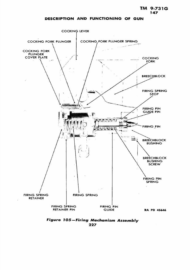
XXIII. Description and functioning  ofgun ....................

XXIV. Description and functioning ofmount ..................

XXV. Operation of gun ...........

XXVI. Lubrication of gun and mount.

XXVII. Sighting equipment .........

XXVIII. Ammunition ...............

REFERENCES .............................

INDEX ............... ..................

M10A1

Paragraphs Pages

118-124 173-187

125-131 188-203

132-135 204-205

136-139 206-208

140-142 209-213

143-148 214-236

149-156  237-248

157-163  249-255

164-168 256-258

169-172 259-262

173-176 263-271

272-274

275-283

7/29/2019 TM9_731G_1943

http://slidepdf.com/reader/full/tm9731g1943 4/284

TM 9-731G

3-INCH GUN MOTOR CARRIAGE M10A1

.2

«.

2

u.

£

O).0*c

0u

o0

eO

w

101

7/29/2019 TM9_731G_1943

http://slidepdf.com/reader/full/tm9731g1943 5/284

TM 9-731G 1-2

3-INCH GUN MOTOR CARRIAGE M10A1

PART ONE

OPERATING INSTRUCTIONS

Section I

INTRODUCTION

Paragraph

Scope .............................................. 1

Records............................................

2

1. SCOPE.

a. This manual is published for the information and guidance ofthe personnel of the using arms charged with the operation and main

tenance of this materiel.

b. The manual contains descriptions of the major units and their

function as well as instructions for operation, inspection, minor repairs,

and unit replacement. Sections I through VII contain informationchiefly for the guidance of operating personnel. Sections VIII through

XXI contain information intended chiefly for the guidance of per

sonnel of the using arms doing maintenance work. Sections XXII

through XXVIII contain information on armament for the operating

personnel and using arms.

c. If repairs, modifications, or adjustments are beyond the scope ofthe using arm personnel, do not attempt them. Notify responsible

ordnance service in order that trained personnel and suitable equipment may be provided, or proper instructions issued.

2. RECORDS.

a. An accurate record must be kept of each motor vehicle issued by

the Ordnance Department. For this purpose, the Motor Book forOrdnance Vehicles (O.O. Form 7255), generally called "Log Book,"is issued with each vehicle and must accompany it at all times. This

book furnishes a complete record of the vehicle, from which valuable

information concerning operation and maintenance costs, etc., is obtained, and organization commanders must insist that correct entries

are made. This book will habitually be kept in a canvas cover to pre

vent its being injured or soiled. The page bearing a record of assignment must be destroyed prior to entering the combat zone. All other

references which may be posted regarding the identity of the organiza

tion must be deleted.

7/29/2019 TM9_731G_1943

http://slidepdf.com/reader/full/tm9731g1943 6/284

TM  9-731C 3-4

Section II

DESCRIPTION  AND TABULATED DATA

Paragraph

Description of vehicle................................. 3 

Tabulated data ...................................... 4

3. DESCRIPTION  OF VEHICLE.

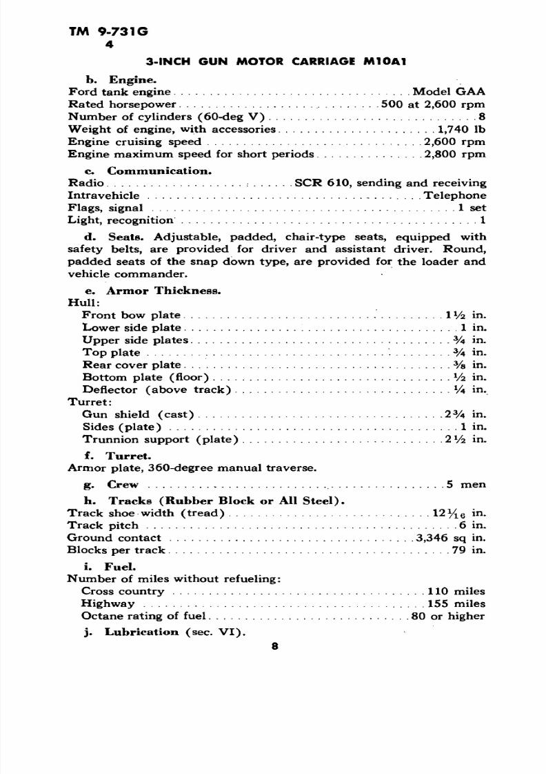
a. General. The 3-inch Gun Motor Carriage M10A1 is an ar

mored, full track laying vehicle, powered by a 500-horsepower Ford

tank engine which is an 8-cylinder, liquid-cooled, V-type engine de

signed specifically for tanks. The engine is located in the rear of thehull. The chief armament consists of a 3-inch Gun M7, in an open top

turret of welded armor plate, which is mounted on the all-welded hull

or armor plate. A cal. .50 antiaircraft machine gun is mounted at the

rear of the turret opening. A consistent use of sloping -surfaces on both

hull and turret greatly reduces the vulnerability of the vehicle to

damage by gunfire. The turret has no revolving turret platform

(basket) such as is used in tanks. 

b. Controls. The vehicle is steered by means of levers, which

operate steering brakes in the 1-piece differential housing. Braking iseffected by pulling back both steering brake levers at the same time.

Two types of parking brakes have been used. In the original design, the

parking  brake operates on a drum on the transmission output shaft

(fig. 7). In the later design, a means of locking the steering brakes

(fig. 8) is provided which permits their use as parking brakes. The

syncromesh transmission has five  forward speeds and one reverse.

c. Communication. The vehicle is equipped with a 2-way radio

for outside communication, and with an intravehicle telephone system

(interphone) serving all of the crew with the exception of the loader,

d. Trailer for Ammunition.  A special pintle hook at the rear of

the vehicle  (fig. 2) provides  for attaching a 2-wheel ammunition cart

carrying munitions to supplement the supply stowed  within the

vehicle.

4. TABULATED DATA.

a. General.

Weight without armament, auxiliary armor, water, fuel, andcrew ............................................ 54,000 Ib

Ground pressure, per sq in............................. 13 Vi IbWidth, over-all ........................................ 10 ft

Length, over-all ................................ 19 ft 7 Vs in.Height, over-all ................................. 8  ft 1% 6 in.

Ground clearance (under final drive housing) ............. 17 3/8 in.

Tread (center to center of tracks) ........................ 83 in.

5

7/29/2019 TM9_731G_1943

http://slidepdf.com/reader/full/tm9731g1943 7/284

TM 9-731G

3-INCH GUN MOTOR CARRIAGE M10A1

i.

gat

Q>

1

•c*r

8,'Z 

e

O

|

3i

o>

7/29/2019 TM9_731G_1943

http://slidepdf.com/reader/full/tm9731g1943 8/284

TM 9-731G 4

DESCRIPTION AND TABULATED DATA

0)•».

etIia0

o

u

nI

CO

0)

7/29/2019 TM9_731G_1943

http://slidepdf.com/reader/full/tm9731g1943 9/284

TM  9-731G4

3-INCH GUN MOTOR CARRIAGE M10A1

b. Engine.

Ford tank engine................................. Model  GAA

Rated horsepower............................. 500 at 2,600 rpmNumber of cylinders (60-deg V) ............................. 8

Weight of engine, with accessories.... .................. 1,740 Ib

Engine  cruising speed ............................... 2,600 rpm

Engine maximum  speed for short periods  ............. 2,800 rpm

c. Communication.

Radio.......................... SCR 610, sending and receiving

Intravehicle ...................................... Telephone

Flags, signal .......................................... 1 set

Light, recognition ......................................... 1

d. Seats.  Adjustable, padded, chair-type  seats, equipped  with

safety belts, are provided fo r driver and assistant  driver. Round,

padded seats of  the snap down type, are provided for the loader  and

vehicle commander.

e. Armor Thickness. 

Hull:

Front bow plate.................................... 1V4  in.

Lower side plate ................'...................... 1 in.Upper side plates ................................... . 3A in.

Top plate ......................................... .^ in.

Rear cover plate .................................... . 3/a in.

Bottom plate  (floor) ................................. l/2  in.

Deflector  (above track).............................. 1A in.

Turret:

Gun shield (cast) ................................. .2 3/4 in.

Sides(plate) ........................................ 1 in.

Trunnion support (plate) ............................ 2 Vz in.

f. Turret.

Armor plate, 360-degree manual traverse.

g. Crew ......................................... 5 men

h. Tracks (Rubber Block or All Steel).

Track shoe width (tread) ............................ 12% 6  in -

Track  pitch ........................................... 6 in.

Ground contact ................................. .3,346  sq in.

Blocks per track....................................... 79 in.

i. Fuel.

Number of miles without refueling:

Cross country ................................... 110  miles

Highway ...................................... 155 miles

Octane rating of fuel............................ 80 or higher

j. Lubrication (sec. VI).

8

7/29/2019 TM9_731G_1943

http://slidepdf.com/reader/full/tm9731g1943 10/284

TM 9-731G 4

DESCRIPTION AND TABULATED DATA

aa.

8-

01

0)

Ie

O•Cw

I0)

7/29/2019 TM9_731G_1943

http://slidepdf.com/reader/full/tm9731g1943 11/284

TM 9-731G4

3-INCH GUN MOTOR CARRIAGE M10A1

0

ut

.ft0)

o

0

O)•Is

Io

I"O

10

7/29/2019 TM9_731G_1943

http://slidepdf.com/reader/full/tm9731g1943 12/284

TM 9-731G

DESCRIPTION  AND TABULATED  DATA

k. Performance. 

Maximum speeds for  various gears:

Maximum speed, 1st gear ............................ 2 mphMaximum speed, 2nd gear .......................... .6 mph

Maximum speed, 3rd gear .......................... 10 mph

Maximum  speed, 4th gear  .......................... 16 mph

Maximum speed, 5th  or high gear.................... 26 mph

Maximum speed, reverse ............................ 3 mph

1. Limitations of the Vehicle.

Maximum recommended sustained speed (on hard road) . . .26 mph

Maximum speed for short periods..................... .28  mphMaximum  allowable engine speed ................. .2 ,800  rpm

Minimum engine idling  speed ......................... 500 rpm

Maximum grade ascending ability ................... 50 percent

Maximum grade descending ability  .................. 50 percent 

Maximum width of ditch vehicle will cross.. . ............ 7 ft 5  in.Maximum vertical obstacle, such as a wall, that vehicle with rub 

ber tracks without grousers will climb over................ 18 in.Maximum fording  depth  (at slowest speed) ............... 36 in.

m. Fuel and Oil Capacities.

Engine oil pan........................................ 32 qt

Power train (transmission differential and final drive) ....... 152 qt

Cooling system ...................................... 17 galFuel tanks (total) ................................... .192 gal

Right rear tank.................................. . 39V2 galLeft rear tank.................................... 39 Va galRight front tank.................................... 58 gal

Left front tank..........................:

.......... 55 gal

11 

7/29/2019 TM9_731G_1943

http://slidepdf.com/reader/full/tm9731g1943 13/284

TM 9-731G

5

3-INCH GUN MOTOR CARRIAGE  M10A1

Section  III

OPERATION AND CONTROLS

Paragraph

General information on instruments and controls........... 5

Prestarting inspection ................................ 6

Starting instructions ................................. 7

Engine test ......................................... 8

Stopping the engine. ................................. 9

Operating thevehicle..................................

10Towing instructions .................................. 11

5. GENERAL INFORMATION ON IN STRUMENTS AND CON

TROLS.

a. Instrument  Panel (fig. 6). 

(1) GENERAL. The instrument panel is located on the left sponson

to the left of the driver as shown in figure 6, and includes  the following instruments and devices:

(a) Circuit Breakers. Seven circuit breaker buttons are providedin the upper left-hand corner of the  instrument panel. These buttons

are pressed to reclose the circuit breakers which take the place of the

conventional fuses. In each instance when  these circuits are over

loaded, the circuit breaker will open. There is little  reason for the

operator of the vehicle to remember which button controls a specificcircuit, since it requires only a  fraction of  a second to press all seven.

(b) Fuel Cut-off Switch Button. To the left of the ignition switch

a push button switch is provided which operates the carburetor de-gasser units electrically. When  stopping the engine, always push the

button in and hold in this position until the engine stops. This shuts

off the fuel from the idle fuel  supply wells in the carburetors and

starves the engine. This must be done  before turning the engine off.(c) Utility Outlets. Two utility outlets that permit plugging in

trouble lights, etc., are provided at the top of the instrument panel.

(d ) Ammeter. To the  right of the clock, an ammeter is provided

with a range of a 100-ampere discharge to a 100-ampere charge. If,

during normal operation, when little current is being used, the am

meter consistently indicates discharge, either the generator regulator is

not functioning properly or the generator itself is at fault (par. 71 d).

In either case the battery is not being charged.  These units should

receive immediate attention to prevent failure during operation. If the

ammeter indicates more than a 100-ampere charge, the current limit

ing unit in one or both of the generator regulators probably is at fault.

Notify ordnance maintenance personnel  to avoid burning out the 

generator.

12

7/29/2019 TM9_731G_1943

http://slidepdf.com/reader/full/tm9731g1943 14/284

TM 9-731G5

OPERATION AND CONTROLS

(e) Ignition Switch. The engine uses two 4-cylinder "Bosch" mag

netos which are controlled by a 4-position switch in the center of the

instrument panel at the top. When the switch lever is all the way to

the left, both magnetos are on. When the switch lever is at the posi

tion marked "L," the left-hand magneto only is on, and the engine will

run on the left-hand four cylinders only (left or right is as viewed

from the rear of the vehicle when facing the same direction as the

vehicle is headed). When the ignition switch lever is at the position

marked "R," the right-hand magneto is on and the engine will run on

the right-hand four cylinders only.

(f) Voltmeter. To the right of the ammeter, a voltmeter having a

range from 16 to 32 volts is provided. When the battery master switchis off, the voltmeter will read at the lower end of the scale. When the

master switch is on, the voltmeter should read battery voltage (ap

proximately 24 volts). If the reading is low with the engine not run

ning and no electrical energy is being used, the batteries are low in

charge and should be recharged. At normal operating speeds during

normal ambient temperatures, the voltage should not exceed 30 volts.

If the reading is greater than this, the generator regulator probably is

not properly limiting the voltage. Notify ordnance maintenance per

sonnel to avoid burning out the generator.

(g) Blackout Driving Light Switch. The blackout driving light may

be used to supply illumination for driving when the service driving

lights might reveal the position of the vehicle. First, remove both

service head lamps from their sockets at the front of the vehicle; then

insert the blackout driving lamps in the lamp sockets. These lamps

when not in use are carried behind the driver and assistant driver's

seats. With the switch marked "LIGHTS" pulled out to first position,

pull out on blackout drive light switch button, to turn on driving light.

The blackout head lamp, marker lamps, tail lamps, and stop light will

also be on with switches in this position. CAUTION: Under battle

conditions, the blackout driving light should be used intermittently

and only when absolutely necessary for safe vision.

(h) Starter Button. To the right of the blackout drive switch, a

starter button is provided. With the battery master switch on and

when the button is pushed in, the circuit is completed through the

starter solenoid closing the starting motor circuit and causes the start

ing motor to crank the engine.(i) Tachometer. The tachometer is located on the right-hand side

of the instrument panel. The throttle stop screw on the carburetor

should be so adjusted that the engine will idle at 500 revolutions per

minute after warmed up. The maximum speed of the engine is gov

erned by a flyball type governor located at the rear of the right-hand

cylinder head. This governor is set to limit the engine speed to 2,600

revolutions per minute under full load with wide open throttle (10

13

7/29/2019 TM9_731G_1943

http://slidepdf.com/reader/full/tm9731g1943 15/284

TM 9-731G

5

3-INCH GUN MOTOR CARRIAGE M10A1 

"

14

7/29/2019 TM9_731G_1943

http://slidepdf.com/reader/full/tm9731g1943 16/284

A—CR

T

B

FO

RG

H

U

LT

O

CR

T

B—CR

T

B

FO

SR

N

CR

T

C—CR

T

B

FO

L

H

U

LT

O

CR

T

DCR

T

B

FO

FU

C

O

A

H

LAM

CR

T

ECR

T

B

FO

B

A

O

D

V

SWIT

CR

T

F—CR

T

B

FO

CR

T

FO

P

LG

FU

G

W

A

T

M

U

LOW OL

P

LG

WA

B

L

SG

LG

OL

L

G

V

M

A

T

MS

O

OL

T

M

U

G

G—CR

T

B

FO

FIRE D

O

SGNA

CR

T

HFU

C

O

SWIT

B

O

J—U

LT

O

K—AM

L—IG

TO

SWIT

M—VO

M

N—B

A

O

D

VN

LG

SWIT

O

O—S

B

O

P—T

m9

Q—LG

SWIT

R—FR

D

O

SGNA

S—FR

D

O

T

LG

T—FR

D

O

T

SWIT

U—IN

M

N

P

LG

V—T

MS

O

OL

T

M

U

G

W—OLL

G

X—OL

P

G

r» O

Y—LOW OL

P

SG

Z—S

D

A

—T

P

ML

R

§

B

—EN

N

B

L

SG

C

—EN

N

T

M

U

G

D

—C

O

E

—FU

L

G

F

—S

O

SWIT

G

—P

LG

R

O

SWIT

RA PD 2

O

7/29/2019 TM9_731G_1943

http://slidepdf.com/reader/full/tm9731g1943 17/284

TM 9-731G

5

3-INCH GUN MOTOR CARRIAGE  M10A1

inch vacuum). If during operation under full load it is possible  to run

the engine speeds above 2,600  revolutions per minute, or if the gov 

ernor limits the  speed at some point below 2,600 revolutions perminute, the ordnance maintenance personnel will  be notified. If the 

governor is set too low it will be impossible  to get maximum  speed 

and power from  the vehicle. If the governor is set too high, damage

to the engine and other working  parts could result.

(j) Light Switch. The knob on  the instrument panel marked

"LIGHTS" controls the service lights and the blackout  driving lights.

A spring-operated safety button prevents the  knob from being  acci

dentally pulled out beyond the blackout position. To release the safety 

button, push the button in with  thumb, at the same time continuing

the outward pull on  the knob  with the first and second fingers. The

switch has three positions (besides off) controlling the  lights as fo l

lows: 

LIGHT SWITCH LIGHTS  OPERATING LOCATIONPOSITION

Blackout Blackout marker lights Top of right and left1st position headlights

Blackout taillights Lower section right and

left taillights

Blackout stop light (when Upper section right-hand 

steering lever is pulled taillight 

back)

Service Service headlights  Right and left headlights 

2nd position Service taillight Upper section left-hand

taillight

Service stop  light (when Upper section left-hand

steering lever is pulled taillightback)

Stop light Service stop light Upper section left-hand

3rd  position taillight

(k) Fire Detector Signal. A  red signal is provided on the right side

of the  instrument panel. The fire detector consists of a 32-candlepower

lamp located behind  a red lens. A wire fro'm this bulb runs back to

the  engine compartment where several  thermal switches will cause  it

to be grounded  in case of fire. The grounding of  this wire completes

the circuit through the bulb with the result that the red light goes on(battery master  switch must be on) warning the operator of the fire

in the engine compartment (par. 5a(l)(m)) .

(I) Fire Detector Test Light. A fire detector  circuit test light is

located  below the fire detector signal and consists of a 3-candlepower

lamp located behind a green lens. Use of this test  light is explained

in  the  following paragraph.

(m) Fire Detector Test Switch. A toggle switch  located to the right

16

7/29/2019 TM9_731G_1943

http://slidepdf.com/reader/full/tm9731g1943 18/284

7/29/2019 TM9_731G_1943

http://slidepdf.com/reader/full/tm9731g1943 19/284

7/29/2019 TM9_731G_1943

http://slidepdf.com/reader/full/tm9731g1943 20/284

TM 9-731G

5

OPERATION AND CONTROLS

v

oa

I

IK

o

a

3

0)

19

7/29/2019 TM9_731G_1943

http://slidepdf.com/reader/full/tm9731g1943 21/284

TM  9-731G 

5

3-INCH  GUN  MOTOR CARRIAGE  M10A1

CLUTCH  PEDAL LEFT  STEERING  LEVER

RIGHT STEERING LEVER 

STEERING LEVER  PAWL

STEERING LEVER PAWL

RATCHET  UP FOOT THROTTLE 

ADJ USTING NUTSKICK   DOWN

TO  LOWER 

RATCHET

KICK BACK TO RAISE  RATCHET

RA PD 28062 

Figure  8—Steering Levers Retractable  Ratchets for Holding

Brakes On

(5)  STEERING LEVERS.  Two  steering  levers  are mounted on the 

floor of the  vehicle, in  front of  the driver's seat. To  steer the  vehicle,

pull  the steering lever on the side  toward which it is desired to turn.

Pulling back either one of the levers slows down  the track on  that

side, while the  speed  of the other track is  increased.

(6)  SERVICE BRAKES. Pulling  back simultaneously  on both steer

ing  levers  slows down  or stops the  vehicle, depending on the  effort applied.

(7) PARKING BRAKE.

(a)  Types  of Parking Brakes.  Two types of parking brakes have

been used  on the  3-inch  Gun Motor Carriage M10A1 as follows: 

1. Original design. The  original design provided a parking  brake 

lever located to the  right of the driver,  at rear of the transmission

(fig. 7). The original design  was a transmission type brake and

20

7/29/2019 TM9_731G_1943

http://slidepdf.com/reader/full/tm9731g1943 22/284

TM 9-73 1G

5

OPERATION AND CONTROLS

TRANSMISSION  OIL COOLER

/FIRE EXTINGUISHER PIPE

LEFT FRONT FUEL TANK VALVE 

LEFT REAR FUEL TANK VALVE ..

RIGHTREAR FUEL

TANK VALVERIGHT FRONT FUEL TANK VALVE

, CLUTCH INSPECTION PLATE

'  RA PD 27697

Figure  9—Fuel Shut-off Valves 

should never be used for any purpose other than parking. Always be

sure this type parking brake is released (all the way forward), before moving the  vehicle.

2. Later design. On later design 3-inch gun motor carriages the

steering levers are each provided with a pawl that operates on retract

able quadrant ratchets (fig. 8). The ratchets are raised by pressing

the ratchet control pedal forward and  down. This permits the steering

lever pawls to engage in the ratchet teeth holding the service brakes

on while parking. To release the service brakes, pull back on both

steering levers and press the ratchet pedal forward and down. This

retracts or lowers the ratchets and the service brakes  are released.

Always be sure that ratchet forward pedal is all the way down before

operating the vehicle.

(8) CLUTCH PEDAL  (fig. 7). The clutch pedal is located on the

floor in front of driver's seat, convenient to the driver's left foot. To

permit shifting of gears, the clutch is   disengaged by depressing the

clutch pedal. At any time when  the clutch pedal free play becomes

less than 2 inches, the clutch pedal should be adjusted (par. 115  d).

Do not ride the clutch pedal.(9) FUEL SHUT-OFF VALVES (fig. 9). Four shut-off valves (one

for each fuel tank) are located on the bulkhead to  the left rear of the

fighting compartment.

(10) BATTERY MASTER SWITCH (fig. 10). The battery master 

switch is located approximately 30 inches to the rear of the driver's

seat. This switch is on  when all the way down. To turn off, raise the

knob approximately one-fourth inch and turn so that switch stays in

7/29/2019 TM9_731G_1943

http://slidepdf.com/reader/full/tm9731g1943 23/284

TM 9-731G5

3-INCH  GUN MOTOR CARRIAGE M10A1

BATTERY MASTER SWITCH RADIO MAS TER SWITCH

RESET BUTTON FOR GUN SOLENOID  CIRCUIT BREAKERRA PD 27988

Figure 10—Battery and Rad io Master Swi tches—Locat ion

its up position. When this switch  is off, all electrical  power is shut off

at the battery (with the exception of the power used by the radio

which is controlled by a separate radio master switch). If  in doubt

as to whether the battery master switch is on or off, the  following can

serve as a guide. When the battery master switch is on, the voltmeter

will show approximately 24 volts. When the battery  master switch is

off, the voltmeter will read at the 16-volt mark. Also when the battery

master switch is on, the oil level gage will indicate the oil,level and

should read in the green section.

(11) RADIO MASTER SWITCH (fig. 10). The radio master switch

is located directly back of the battery master switch and turns on and

off the same way as outlined  above for the battery master switch.

(12) FIRING  SOLENOID CIRCUIT BREAKER (fig. 53). A circuit

breaker located in the battery box opens the circuit of the gun firing 

solenoid and relay if it should become overloaded. The button con

trolling the  circuit breaker (fig. 10) is located on top of the battery

box to the rear of the radio master switch. Pressing this button will

reset the circuit breaker.

(13) GEARSHIFT LEVER (fig. 7).

(a) Description. Shifting of gears in the transmission for speed

changes is accomplished by the gearshift lever, located on the left side 

of the transmission, to the right of the driver. The positions of the

gearshift lever for the various speeds are shown in figure 11. The gear

shift lever is equipped with a latch which prevents accidental shifting

into first speed  or reverse. The latch must be released by  pressing

7/29/2019 TM9_731G_1943

http://slidepdf.com/reader/full/tm9731g1943 24/284

TM 9-731G

OPERATION AND CONTROLS

if

RA PD 27493

Figure 11—Gearshift Lever Positions

down the button on top of the  lever before shifting into first speed or

reverse. 

(b) Operation.  When it is desired to shift to low or reverse, the

following procedure  will make the shift possible without the clashing 

of gears which otherwise usually results. From neutral,  move the gearshift lever as though to shift into third gear. Maintain  pressure in

this direction long enough to stop the propeller shaft and then, with

the clutch still held  out, shift smartly into low or  reverse. If whenshifting to any of the higher speeds, there is a raking of gears, go back

to neutral and, still holding the clutch out, start the shift over.  Do not 

attempt to complete a  shift  that begins with  a clashing of gear teeth.

(14) FIRE  EXTINGUISHER OPERATION AND CONTROLS.

(a) Portable Extinguishers. Carry portable extinguisher in left hand 

and hose in right hand. Direct the discharge at base of flame, with discharge  cone as  close to flame as operator can safely hold it. Increase

the discharge from extinguisher as the  fire is put out. 

(b) Fixed Extinguishers. In case  of a  fire in  the engine compart ment, the fixed extinguisher can be set in operation from  the outside of

the vehicle by  means of the controls located behind and to the  left

of the turret (fig.  12) or by means of the controls in the driver's com 

partment located almost directly over the driver's  left shoulder. In

23

7/29/2019 TM9_731G_1943

http://slidepdf.com/reader/full/tm9731g1943 25/284

TM 9-731G 5-7

3-INCH GUN MOTOR CARRIAGE M10A1

RIGHT FRONT FUEL TANK FILLER CAP

COOLING SYSTEM FILLER CAP

4i>7 \ *•-* BRIGHT REAR FUEL TANK FILLER CAP "

' LEFT REAR FUEL TANK FlulTCAP LEFT FRONT FUEL TANK FILLER CAP

I RA PD 27693

Figure 12—Fuel and Water Fillers

either case the left-hand control, when pulled out, opens one fixed

extinguisher, and the right-hand control opens the other extinguisher.

Either floods the engine compartment with carbon-dioxide gas, and

will extinguish a fire with the engine running up to 1,200 revolutions

per minute. If conditions permit, however, stop the engine.(15) PERISCOPES. Two periscopes are provided for the driver, one

in the driver's door, the other to his left, mounted in the hull top plate.

A third periscope is in the assistant driver's door. Each periscope ismounted in a revolving plate which permits vision in any direction.

The periscope mounts can be tilted to raise or lower the line of vision.

Lock screws are provided to hold the mounts stationary when desired.

Each periscope is held in place in its mount by a knurled nut on the

back. A safety lock on the periscope housing prevents the device from

falling out if the holding nut becomes loosened. Two spare periscopesand six spare heads are carried in boxes mounted on top of the trans

mission.

The vehicle has a crew of five men and

it is essential that all men be utilized in inspection of the vehicle under

the direction of the vehicle commander. The inspection should cover

the vehicle as well as the engine (par. 19).

Before attempting to start the engine, familiarize

yourself with all of the various instruments and controls (par. 5).

Make sure that the function of each instrument and control is thor

oughly understood, and that the significance of the readings on the

various instruments is appreciated.

F). Open fuel shut-off

24

7/29/2019 TM9_731G_1943

http://slidepdf.com/reader/full/tm9731g1943 26/284

7/29/2019 TM9_731G_1943

http://slidepdf.com/reader/full/tm9731g1943 27/284

7/29/2019 TM9_731G_1943

http://slidepdf.com/reader/full/tm9731g1943 28/284

7/29/2019 TM9_731G_1943

http://slidepdf.com/reader/full/tm9731g1943 29/284

TM  9-731G 11

3-INCH GUN  MOTOR  CARRIAGE M10A1 

If there are tracks on the  vehicle

to be towed, always disconnect the propeller shaft at the  transmission

companion flange and leave the vehicle  in fifth gear. This  procedureinsures  adequate circulation of the transmission  oil while  the vehicle

is in motion.  If the tracks are  removed before towing the  vehicle, this

precaution  is not necessary. In towing,  there  are several  precautions

that the driver must  take to avoid trouble  or unnecessary  delay.

Changes of direction are always to be made by a  series of slight  turns

so that  the vehicle being towed is as nearly as possible, directly

behind or "tracking" the  one doing  the towing. This will prevent the 

cable  from contacting the track,  which might damage both the cable

and the track  blocks. Soft muddy ground  is to be avoided, since the tracks may slip on such a surface.  If it is  necessary to cross a  muddy 

area, the driver should be careful to straighten out  both vehicles 

before entering it, as it  is more difficult to pull at an angle  than  when

following in  tow. On  vehicles equipped  with rubber block tracks,

grousers may be  installed as required. The  maximum speed when

towing should be not more than  12 miles per hour and then only with 

an operator for steering and braking the  towed  vehicle.

Except in cases  where a  "short 

hitch" is absolutely  necessary a towing cable will not be  coupled to another vehicle by  other  than the thimbled eyes provided  at both

ends. Doubling  the cable  causes  sharp  bends in the  wire rope which

will cause rapid failure of the strands and will  leave  the cable ex 

tremely dangerous to handle. When  a "short hitch" is desired,  the

two  eyes of the cable are  attached to the towing vehicle. The  cable

with  leads crossed,  is then passed  through both  shackles of the  towed

vehicle. This provides an arrangement having a minimum of bending 

action and movement at the shackles, and furnishes clearance between

cable and tracks.

If no operator is available to steer the dis

abled  vehicle, one cable will facilitate tracking  of the  towed  vehicle.

Care must be taken  on  turning, not  to get  the cable tangled up with

the track  of either vehicle.

28 

7/29/2019 TM9_731G_1943

http://slidepdf.com/reader/full/tm9731g1943 30/284

TM 9-731G12-13

Section  IV OPERATION UNDER UNUSUAL CONDITIONS

Paragraph

Cold weather starting ................................ 12

Operation at high temperatures.  ........................ 13 

Operation at high altitudes. ........................... 14

Operation in sand....................................  15

Operation on slippery terrain...........................  16

Operation under dusty conditions. ...................... 17

When starting the engine in cold weather, it is doubly important to follow the starting procedure 

outlined  in paragraph 7  c. If this procedure is followed,  few addi

tional instructions are required. Briefly stated, cold weather starting

problems are nearly always  the result of poor preparation or main

tenance of the vehicle and in addition  to the causes of  failure to start

as outlined in paragraph 36, can be attributed either to  the engine oilbeing too heavy for  the temperatures encountered or the batteries

being low  in charge. In sub-zero temperatures,  a battery  that has set

over night  will have a capacity much  lower than at normal tempera tures.

CAUTION: If the  engine is forced to turn

over while  there is water, antifreeze, or oil in  the cylinders above the

pistons (as a result of condensation or leakage), breakage of internal

parts of the engine will result. Turn the engine over three complete

revolutions by hand (fig. 35) prior to  towing. Never use other than

fifth gear (fig. 11) when towing the vehicle to  start  the engine.

(1) TURN ENGINE OVER. Leave the ignition switch off. Tow the

vehicle several feet with the transmission in neutral (fig. 11) to remove the slack from the towing line and to  break the track loose 

from the frozen ground.  Depress the clutch and place the gearshift

lever in fifth gear (fig. 11). Tow the vehicle at  1 mile per  hour and

engage the clutch gradually  (permitting it to slip) until two  complete

revolutions of the engine have been made. If the  engine will not turn

over with the clutch slipping, discontinue  attempting to start and

notify ordnance maintenance personnel.

(2) START THE ENGINE. After the engine has been turned  over as

outlined above, turn the ignition  switch on  and engage the  clutch.Increase towing speed to from 3 to 5 miles  per hour (in fifth gear,

fig. 11) and make from 3 to  5 strokes with the priming pump. If theengine  does not start, see paragraph 36.

a. When operating at high temperatures, observe the engine  tem

perature gage frequently and add water to  the cooling system as often

29 

7/29/2019 TM9_731G_1943

http://slidepdf.com/reader/full/tm9731g1943 31/284

TM 9-731G13-17

3-INCH GUN MOTOR CARRIAGE Ml OAT

as may be required to prevent overheating. The viscosity of the various

oils used decreases at higher temperatures. Be sure oils are being used 

with sufficientbody to 

match the temperature. Engine oil thinned out

by high temperatures is used up more rapidly. Check the  engine oil

level frequently.

a. High altitudes result in a lowering of compression due to lowered

atmospheric pressure and a corresponding lowering of the developed

horsepower. Due to rarefied atmosphere, a smaller  quantity of air is  

taken into each cylinder while the quantity of fuel remains practically 

the same as at sea level. This results in the fuel air mixture being toorich. This  can only be remedied by reducing the size of the various

carburetor jets if the vehicle  is to be operated continually at high

altitudes. Generally speaking, elevations up to 5,000 feet present no

particular problems and  can be considered as normal.

a. Desert operation and operations under extremely sandy road

conditions may necessitate cleaning the air cleaner as often as every

2 hours. When operating  in sand deep enough to force the use of  lowergear rations, do  not exceed the speed specified for the particular gear

ratio (par. 4  k).

a. For operation in mountainous terrain, in mud, or over ice.and

snow, where sufficient traction is  not normally possible, grousers are

provided for use on certain types of track. When operating on slippery 

terrain start vehicle carefully by engaging clutch gradually; do not

attempt  to turn until after vehicle is moving at normal speed. Tracks

and bogies should be periodically cleaned of mud, snow, or ice.

a. In operating the vehicle cross country on dry, dusty ground

along with other vehicles, avoid running  in the dust cloud of other

vehicles as  much as possible. When operating in single file on dusty

roads where no cross wind exists, space the vehicles far enough apart 

to reduce the dust hazard as much as possible if practicable. Evenwhen the above precautions are taken, it may be necessary to clean 

the air cleaner as often as every 2 hours (par. 55). If the air cleaners

are kept clean and  their oil level is maintained, little damage to the 

engine will result. On the other hand, if the  air cleaners run  dry, it is

possible to wear out an  engine in 1  hour or less.

30

7/29/2019 TM9_731G_1943

http://slidepdf.com/reader/full/tm9731g1943 32/284

7/29/2019 TM9_731G_1943

http://slidepdf.com/reader/full/tm9731g1943 33/284

7/29/2019 TM9_731G_1943

http://slidepdf.com/reader/full/tm9731g1943 34/284

7/29/2019 TM9_731G_1943

http://slidepdf.com/reader/full/tm9731g1943 35/284

7/29/2019 TM9_731G_1943

http://slidepdf.com/reader/full/tm9731g1943 36/284

TM 9-731G 

20-21

PREVENTIVE MA INTENANCE INSPECTIONS  AND SERVICE 

(5) ITEM 31,  ENGINE AND CONTROLS. Note power when accelerat

ing, excessive smoking, detonation, misfiring, stalling, or overheating.

Test governor control. Maximum  full load speed is 2,600 revolutions

pef minute.

(6) ITEM 32, INSTRUMENTS.

(a) Oil Pressure Gage. Must register 60  to 80 pounds at operating

speeds. Stop engine if red indicator light comes on.

(b) Ammeter. Will show  a high charging rate for  first few minutes.

A high charging rate for extended period with all electrical units turned 

off, indicates a discharged battery or  faulty regulator.

(c) Engine Temperature Gage. Normal reading is 60 F  above at

mospheric temperature. Should reading exceed  235 F, stop engineand investigate.

(d) Transmission  Temperature Gage. Reading must not exceed

200  F.

(e)  Tachometer. Must register engine speed and accumulated

crankshaft revolutions.

(t) Speedometer. Must register correct speed and accumulated

mileage without noise.

(g) Voltmeter. Reading should not exceed  30 volts.

(h) Fuel Gage. Must show correct amount of fuel in each  of thefour tanks.

(i) Fire Detector Signal. Operate test switch to determine whether

fire  detector  system is working. Green light should go on if system is

in  satisfactory condition.

(j) Engine Oil Level Gage. Pointer should  remain in the green

sector. Should pointer indicate in   the red sector, stop engine  and

investigate.

(k) Engine Boil Signal. This signal should light  when temperature

in the cooling system reaches 235 F.  If signal lights, stop and investigate cause of overheating.

(7) ITEM  36, GUNS AND MOUNTINGS, ELEVATING, TRAVERSING,

AND FIRING  CONTROLS. While the  vehicle  is in operation, but before

it  is used in combat, check manual turret traversing controls and gun

elevating, and firing controls to be sure that all mechanism responds

properly.

a. At-halt services may be regarded as minimum maintenance pro

cedures and should be performed under all tactical conditions even

though more extensive maintenance services  must be slighted or

omitted  altogether.

At-halt Services consist of investigating  and de

ficiencies noted  during operation, inspecting items listed below  ac

cording to  the procedures following  the items, and correcting any

35

7/29/2019 TM9_731G_1943

http://slidepdf.com/reader/full/tm9731g1943 37/284

TM 9-731G21-22

3-INCH GUN MOTOR CARRIAGE M10A1

deficiencies found. Deficiencies not corrected should be reported

promptly to the designated individual in authority.

(1) ITEM 39, TEMPERATURES (HUBS AND FINAL DRIVES). Hand-

feel the hubs of sprockets, idlers, bogie wheels, and track support

rollers to determine whether or not they are abnormally hot.

(2) ITEM 38, FUEL, OIL, AND WATER. Determine quantity of fuel,

oil, and water to make sure supply is adequate for mission. Add if

necessary.

(3) ITEM 45, TRACKS. Remove stones and other material. Inspect

tracks for correct tension, loose, worn or missing connectors and

wedges and also worn, damaged, or dead blocks.

(4) ITEM 42, SPRINGS AND SUSPENSIONS. Examine suspensionsfor broken or loose parts. Remove any debris lodged in bogie assem

blies.

(5) ITEM 44, SPROCKET NUTS. Examine sprocket cap screws and

hub nuts to determine that they are present and secure.

(6) ITEM 46, LEAKS, GENERAL. Examine bottom of hull and

ground under vehicle for evidence of any leaks. Inspect the hull, fight

ing compartment, and engine compartment for fuel, oil, or water leaks.

Tighten any loose connections.

(7) ITEM 50, TOWING CONNECTIONS. Towing shackles, pins, andpintle hook must be in usable condition.

(8) ITEM 47, ACCESSORIES AND BELTS. Investigate possible causes

of improper operation or performance noted during operation. Ex

amine generators, starter, and water pump for security of mounting.

Examine generator belts for good condition.

(9) ITEM 48, AIR CLEANERS. When operating under extremely

dusty conditions, clean air cleaners as often as required when tactical

situation permits. Examine filter elements. Clean and replace oil if

necessary.(10) ITEM 52, APPEARANCE AND GLASS. Thoroughly inspect ex

terior of vehicle for missing pioneer equipment. Inspect all lights and

vision devices. Clean if necessary. See that all covers and hatches can

be closed and locked securely.

a. After-operation service is particularly important because at this

time the driver inspects his vehicle to detect any deficiencies that may

have developed, and corrects those he is permitted to handle. Heshould report promptly, to the designated individual in authority the

results of his inspection. If this schedule is performed thoroughly, the

vehicle should be ready to roll again on a moment's notice. The before-

operation service, with a few exceptions, is then necessary only to

ascertain whether the vehicle is in the same condition in which it was

left upon completion of the after-operation service. The after-opera

36

7/29/2019 TM9_731G_1943

http://slidepdf.com/reader/full/tm9731g1943 38/284

7/29/2019 TM9_731G_1943

http://slidepdf.com/reader/full/tm9731g1943 39/284

TM 9-731G22

3-INCH GUN MOTOR CARRIAGE Ml OAT

tracks. Look for loose and worn track connectors and wedges. Note if

tracks have 3/4-inch sag between upper track support rollers.

(b) Weekly. Tighten all track wedges securely. Examine trackscarefully for worn guides and blocks, also dead blocks. Adjust track

tension so as to have 3/t-inch sag between rear track support rollers.

11. ITEM 69, * SPRINGS AND SUSPENSIONS.

(a) Examine the volute springs for abnormal sag and breakage.

Volute springs are unserviceable when two or more coils contact lower

spring seat. Look for looseness, wear, damage, and grease leaks of

bogie frames, arms, and rollers. Remove all stones and trash lodged in

bogie assemblies.

(b) Weekly. Tighten all bogie brackets, sprockets wheels, upper

and lower rollers, mounting bolts and nuts, or cap screws.

(12) ITEM 77, TOWING CONNECTIONS. Examine towing shackles,

pintle hook, and lifting eyes to see that they are in serviceable condi

tion. Make sure pintle hook latch operates freely. Lubricate if

necessary.

(13) ITEM 64, *ELECTRICAL WIRING.(a) Examine conduits for damaged condition and tighten all loose

connections.(b) Weekly. Clean all accessible wiring, looking for loose connec

tions and cracked insulation.

(14) ITEM 65, *AiR CLEANERS AND BREATHER CAP.

(a) Remove air cleaners and inspect elements and condition of oil.

If necessary, clean elements and refill with oil to "LEVEL" mark on

body. Examine condition of gaskets before installation.

(b) Weekly. Clean both air cleaners and breather cap and refill air

cleaners with oil.(15) ITEM 66, *FUEL FILTERS.(a) Remove plug and drain water and sediment.

(b) Weekly. Clean element and bowl.

(16) ITEM 60, FIRE EXTINGUISHER. Inspect portable fire extin

guishers to see that they are in place, securely mounted, and that seals

are not broken. See that red sealing caps on fixed fire extinguisher

cylinder valves are intact. Discharged cylinders must be replaced.

Make sure mountings are tight and nozzles are free from obstruction.

(17) ITEM 62, * BATTERY.(a) Battery connections and mountings must be kept clean and

tight. Electrolyte must be one-fourth inch above plates in each cell.

Add fresh clean water as required. Turn battery master switch and

radio switch to "OFF" position after completing services.

(b) Weekly. Clean battery and terminal connections. Tighten con

nections and battery hold-downs if necessary.

38

7/29/2019 TM9_731G_1943

http://slidepdf.com/reader/full/tm9731g1943 40/284

TM 9-731G22

PREVENTIVE MAINTENANCE INSPECTIONS AND SERVICE

(18) ITEM 81,  TURRET AND GUN MOUNT  MECHANISM AND CON 

TROLS. Release turret lock and gun traveling  lock. Traverse turret full

360 degrees in both  directions.  Elevate and depress gun with hand

mechanism. All mechanisms must  operate  freely and without bind or

excessive play throughout entire limit of travel. Tighten all loose wiring

connections and mountings. Test operation of firing controls and sight

ing equipment. Guns must be cleaned, properly oiled, and covered.

(19) ITEM  59,  LAMPS. If  tactical situation permits, turn all light

switches to "ON" position, inspect all lights to see that they are operat 

ing properly, clean, and securely mounted and go  out when  switches

are  turned off. 

(20) ITEM  80, VISION DEVICES. Clean and install serviceable

periscope heads or assemblies as required.  Mounts must pivot or rotate

without binding.

(21) ITEM  61, DECONTAMINATOR. Must be fully charged and se

curely mounted. Shake to determine contents.

(22 ) ITEM 84, CLEAN VEHICLE. Remove all expended materiel and

clean interior of vehicle thoroughly. Clean exterior as necessary, mak

ing  sure identification markings are visible.

(23) ITEM 83, *LUBRICATE AS  NEEDED.

(a) Oil or lubricate all parts  as required when performing after-

operation service. For specific intervals and lubricants to be used, refer

to War Department Lubrication Guides and section VI.

(b) Weekly. Perform regularly scheduled lubrication if this service

is due.

(24) ITEM 85, *TOOLS AND  EQUIPMENT.

(a) Inspect all tools and equipment for condition, proper mounting,

and serviceability using On  Vehicle Materiel List. Replace missing items and replenish supplies.

(b)  Weekly. Clean all  tools and equipment. Replace items that

are unserviceable.

39

7/29/2019 TM9_731G_1943

http://slidepdf.com/reader/full/tm9731g1943 41/284

TM 9-731G23-24

3-INCH GUN MOTOR  CARRIA GE M10A1

Section VI

LUBRICATION

Paragraph

Introduction ....................................... 23

Lubrication  guide ................................... 24

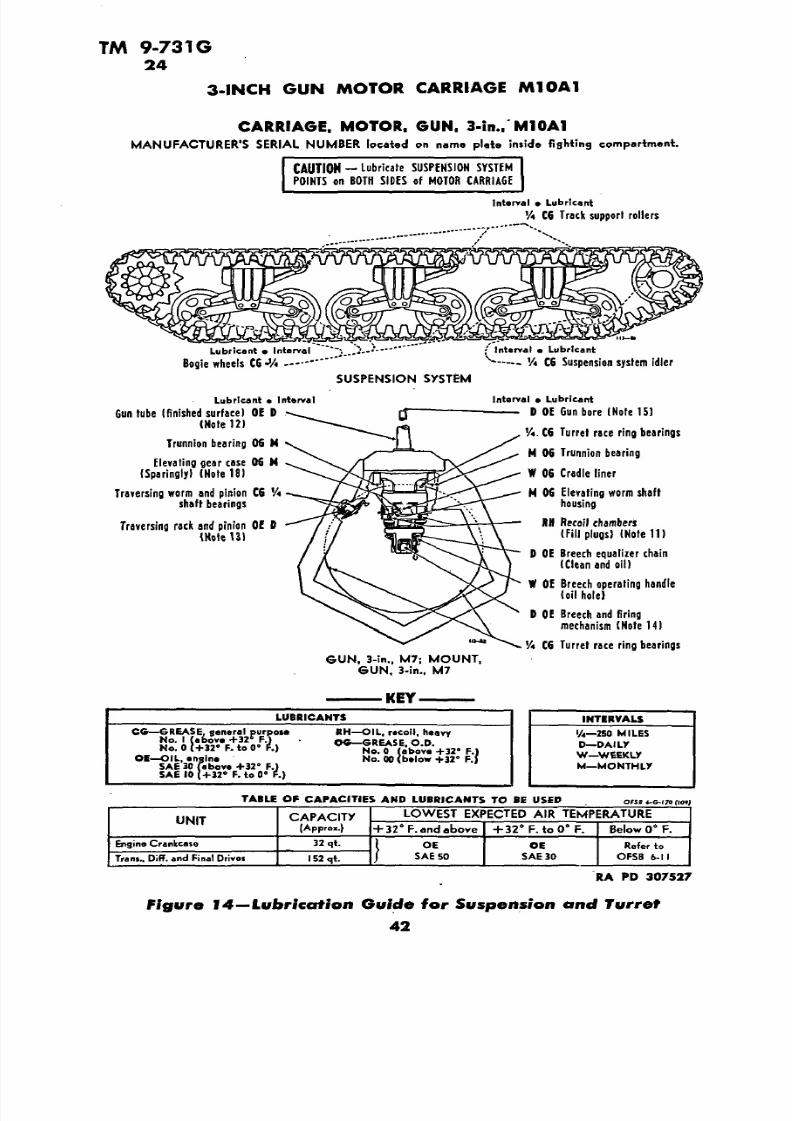
The  following lubrication instructions  fo r 3-inch Gun

Motor Carriage M10A1,  are published for the information and guid

ance of the using arm personnel. Reference is made to OFSB 6-11 and OFSB 6-5 for lubrication  and  service below 0 F. In the field, itmay not be possible to supply a  complete assortment  of lubricants

called fo r by the lubrication guide to meet the recommendations. Itwill be necessary to make the best use of those available, subject to

inspection of  the officer  concerned,  in consultation with responsible 

ordnance personnel.

Lubrication instructions for allpoints to be serviced by the using arms are shown in  War DepartmentLubrication Guide (figs. 13 and 14), which specifies  the types  oflubricants required and the intervals at which they are to be  applied.

Guides from which  information  is reproduced are  10- x 15-inch  lam

inated charts which are part of  the accessory equipment of each piece

of materiel. Data contained in the lubrication guides are binding on

using troops.

The following notes apply  to the lubrication guide  (figs. 13 and  14). All  note references in the guide itself are

to the subparagraph  below having the corresponding number.  In

addition to the items on the guide, other small moving parts, such as hinges and latches, must be lubricated  at frequent intervals.

(1) FITTINGS. Clean before  applying lubricant.

(a) Motor Carriage. Lubricate bogie wheels, idler and track support

rollers, tachometer and speedometer adapters until lubricant overflowsrelief valve. Lubricate other fittings until new lubricant is forced from

the bearing, unless otherwise specified. (b) Armament. Where bearings can be seen, lubricate until new

lubricant is forced from  the bearing. CAUTION: Lubricate suspension

points and armament fittings after washing vehicle.

(2) INTERVALS. Intervals indicated are fo r  normal service. Forextreme conditions of speed, heat, water, sand, mud, snow,  dust, etc.,reduce interval by one-third or one-half, or  more, if  conditions warrant.

40

7/29/2019 TM9_731G_1943

http://slidepdf.com/reader/full/tm9731g1943 42/284

TM 9-731G 24

LUBRICATION 

CARRIA GE, MOTOR, GUN, 3-in., M10A1 

MANUFACTURER'S SERIAL NUMBER located on name plate inside fighting compartment.

Lubricant . Interval | SERVICED FROM FIGHTING

COMPARTMENTDifferential and final driye

drain plugs Interval • Lubricant

Transmission drain plug 3 OE Trans., diff. and final(Reached from under hull)  drives (See Table) (Fill

cap, level gage) (Note 6)

SERVICED FROM EHGIHE1

C6 Speedometer, adapterCO MPirHMEKT

'/. CG Gearshift shaft

(OR THROUGH  REAR DOOR),- 'A OE Parking brake (oil hole)

(SAE 301 

Clutch pilot bearing BR \1 CG Parking brake lever shaft

(Note 7) x 1 CG Universal joint (fitting)

(Note 10)1 CG Slip joint I plug)

fuel flfer (Note 10)(Note 8) 1 CG Universal joint  (fitting)

(Note 10)1 CG Bell housing clutch shaft

Tachometer adapter CG 1bearing(Remove plate above

Universal joint (fitting) CG 1 universal joint housing

(Note 9) to expose fitting) _ _  

Slip joint (fitting) CG 1 \ SERVICED FROM ENGINE(Note 9) COMPARTMENT

(OR THROUGH REAR DOOR)

Universal joint (fitting! CG 1 Vt OE Mr cleaners(Note 9)  (Note 3)

1 OE Starting motor (SAE 301

Accessorydriveshafthousing OE   1 -~ 1 CG Accelerator control rodbearing

(plug)  ISAE 30)Oil filter (Note 5)

(Note 9) 1 CG Universal joints (fittings)(Note 9)

Fan shaft bearing  CG 1 1 OE Accessorydriveshafthousing(fitting) (Sparingly) (plug) (SAE 30)(Note 9)

Crankcase bayonet gage 1  CG Fan shaft bearing  (fitting)1 CG Slip joint (fitting) 

Crankcase breather OE '/<' (Note 91

(Note 3)OE Crankcase (See Table)

(Note 4)

KEY

LUBRICANTS INTERVALS

1/4- 250 MILESOE —OIL, engine BR—GREASE, ball and roller 1—1,000 MILES CG—GREASE,  general purpose

bearing 3—3,000 MILESNo. 1 (above +32° F.) CHECK  DAILY

CrankcaieNo. 0(+32° F. toO" F.) Air cleaner ]

Oil f i l ter

RA PD  307528

Figure 13-Lubrication Guide for Power Drive Units

7/29/2019 TM9_731G_1943

http://slidepdf.com/reader/full/tm9731g1943 43/284

TM 9-731G 24 

3-INCH  GUN  MOTOR CARRIAGE M10A1

CARRIAGE, MOTOR. GUN.  3-in .. M10A1

MANUFACTURER'S SERIAL NUMBER lo cated on name plots in si de f ight ing   compartment.

CAUTION - lubricate SUSPENSION SYSTEM POINTS on BOTH SIDES of MOTOR CARRIAGE

Interval • Lubricant

Vi CG   Track support  rollers

Lubricant • Interval ;' In terval • Lubr icant

Bogie wheels OS-% V—~ '/4 CG Suspension system idler

SUSPENSION SVSTEM

Lubricant • Interval Interval e Lubricant

Gun tube  (finished surface! OE D  DOE Gun  bore (Note 15)

(Note 12)% CG Turret race ring bearings

Trunnion bearing  OS MM OG Trunnion bearing

E levating gear case 06 M 

(Sparingly) (Note 18) W OG Cradle liner 

Traversing  worm and  pinion CG   '/< M  OG E levating worm shaftshaft bearings housing

Traversing rack aid pinion OE D UN Recoil chambers (Note 131 (Fill plugs) (Note 11)

D  OE Breech  equalizer chain(Clean and  oil)

W OE Breech operating  handle

(oil hole)

D OE Breech and  firingmechanism (Note 14)

'/< CG   Turret race  ring bearings

GUN, 3-in., M7; MOUNT, SUN, 3-in., M7

LUBRICANTS INTERVALS

CG— GREASE, general purpose RH—OIL, recoil, heavy 1/4—250 MILESNo. 1 (above +32*F.J   OS-GREASE. O.D.No. 0(+32°F.toO° F.)  D—DAILY

No. 0 (above +32° F.)W—WEEKLYOE—OIL, engine No. 00 (below +32° F.)

SAE 30 (above +32° F.) M—MONTHLYSAE  10 (+32° F.toO" F.)

TABLE OF CAPACITIES AND  LUBRICANTS  TO BE USED

CAPACITX LO WEST EXPECTED AIR TEMPERATUREUNIT 

(Approx.) +32° F. and above +32°F.toO°F . Below 0° F.

Engine Crankcase 32 qt. 1 OE Of Refer to

Tram., Diff. and Final Drives I52qt. / SAE 50 SAE 30 OFSB 6-11

RA PD 307527

Figure Turret

7/29/2019 TM9_731G_1943

http://slidepdf.com/reader/full/tm9731g1943 44/284

7/29/2019 TM9_731G_1943

http://slidepdf.com/reader/full/tm9731g1943 45/284

TM  9-731G 

24

3-INCH GUN MOTOR  CARRIAGE  M10A1 

TRANSMISSION  OIL  a  LEVEL  BAYONET  GAGE

RA PD  27341

Figure  15—Transmission  Oil Bayonet Gage  and  Speedometer Drive

(b)  To  flush, fill cases to about one-half capacity with OIL, engine,.SAE  10. Operate mechanism within  cases slowly  for several  minutes

and redrain. Replace  drain  plug  and refill cases to  correct  level withlubricant specified on  guide.

(7)  CLUTCH PILOT BEARING. At time  of disassembly  of clutch forinspection, replacement,  or overhaul, clean and repack  bearing withGREASE, ball and roller bearing.

(8) FUEL  FILTER. Daily, close  all four fuel line  shut-off valves, remove drain  plug, and drain out sediment  and water. Every  1,000 miles, remove element and wash in Diesel fuel or  SOLVENT, dry-cleaning.

(9) ACCESSORY DRIVE SHAFT HOUSINGS.

(a)  Universal Joints and Slip Joints. Filler plug in housing  is  fitted with  bayonet gage;  fill   to "FULL"  mark  on gage.  Lubricate universaljoints through fittings with GREASE, general purpose  (seasonal grade). There is  no relief valve  in  these joints; do  not use  excessive pressure. To  lubricate slip  joints, apply GREASE, general purpose(seasonal  grade), to fitting until  lubricant is  forced from  end ofspline.

44 

7/29/2019 TM9_731G_1943

http://slidepdf.com/reader/full/tm9731g1943 46/284

TM 9-731G 24

LUBRICATION

-SPRING LOADED DRAIN VALVES (6)

ENGINE COMPARTMENTFLOOR PLATE

• FLOOR PLATE DRAIN PLUG

RA PD  27501

Figure 16—Underside of  Hu ll—from the Rear

(10) MOTOR CARRIAGE DRIVE UNIVERSAL JOINTS AND SLIP JOINT.

Remove  tunnel shield sections over universal joints and  slip joint at

ends of  tunnel shield. To lubricate slip joint, remove plug and insert

fitting. Apply GREASE, general purpose (seasonal grade), to universal

joints until it overflows at relief valve, and to slip joint until lubricant

is forced  from end  of spline. CAUTION:  After lubricating, remove

fitting and replace plug in slip joint.

(11) RECOIL FLUID. Use OIL, recoil, heavy. Capacity is approxi

mately 20 pints each cylinder. For instructions on handling of recoil

fluid , refer to OFSB 6-6.

(12 ) GUN TUBE.  Daily and before firing, clean and oil exposed fin

ished metal surface. Keep  surface covered with thin film of OIL,

engine (seasonal  grade).

(13 ) TRAVERSING RACK AND PINION. Daily, clean and apply OIL, 

engine (seasonal grade).

(14) BREECH AND FIRING MECHANISM. Daily and before and after

firing, clean and oil all moving parts and exposed metal surfaces with 

OIL, engine (seasonal grade). CAUTION: To insure easy breech op

eration and  to avoid misfiring in cold weather, clean with SOLVENT,

dry-cleaning. Dry and lubricate with  OIL, lubricating, preservative,

light. To clean firing mechanism, remove and operate  pin in SOL 

VENT, dry-cleaning.

(15) GUN  BORE. Daily and after firing, clean  and coat with OIL,

engine (seasonal grade).

(16) OILCAN POINTS.  Every 250 miles, lubricate steering and brak

ing rod clevises and  pins, spark and throttle rod end linkage, hinges,

latches, elevating and traversing handwheel handles,  traversing race

7/29/2019 TM9_731G_1943

http://slidepdf.com/reader/full/tm9731g1943 47/284

TM  9-731G 24 

3-INCH  GUN MOTOR  CARRIAGE M10A1

ring and pinion, periscope holder pivots, etc., with OIL, engine (sea

sonal grade).

(17) POINTS REQUIRING NO LUBRICATION SERVICE. These pointsare: clutch release bearing, water pump, bogie wheel suspension link 

age, final drive sprocket bearings.

(18) POINTS  TO BE SERVICED AND/OR LUBRICATED BY ORDNANCE

MAINTENACE PERSONNEL. Generators, throttle control rod jackshaft,

sight and gun  rotor bearings, magnetos, elevating gear case (for dis

assembly and  cleaning), and breech operating shaft bearings.

(1) REPORTS. If lubrication instructions are closely followed,proper lubricants used, and satisfactory  results are not obtained, a

report will be made to  the ordnance officer responsible for the main

tenance of the materiel. 

(2) RECORDS. Record  of seasonal changes  of lubricants and recoil

oil will be kept in the Artillery Gun Book. 

46 

7/29/2019 TM9_731G_1943

http://slidepdf.com/reader/full/tm9731g1943 48/284

TM 9-731G 25

Section VII EQUIPMENT  AND TOOLS ON VEHICLE

Paragraph 

Armament ......................................... 25

Sighting equipment .................................. 26

Miscellaneous accessories and equipm ent. .. .............. 27

Signalling equipment ................................. 28

Rations ............................................ 29

Vehicular tools  and spare parts. ........................ 30

Item Where Carried

a.

(1) 3-INCH GUN M7.

Book, Artillery Gun, O.O. Form 5825 .............. Instruction  bag

Brush, bore, M15  w/staff. ........... Bracket on engine bulkhead

(consisting of

Brush,  bore, M15 B168031

Staff, end B103377

Staff, end B103378

Staff,  middle B124134)

Can, Vi-gal (stencil "OIL RECOIL" in black letters

l/2 in. high on  can)

Case, carrying, gunner's quadrant, Ml............ Bracket in turret 

Cover, bore brush

Cover, breech .................................... On breech

Cover, muzzle ....................................... On gun

Extension, oil  gun

Gun, oil, recoilOil, recoil, heavy, 1-q t (in can BIO 1420)

Quadrant, gunner's, Ml................. Bracket in turret

Rammer, cleaning and unloading, M3

Setter, fuse, M14...................... Tool box under subfloor

Sight, bore

Table, firing .................................. Instruction bag

Table, range and elevation

Target, testing (set of 4)

(2) CAL. .50 MACHINE GUN.Bag, metallic belt link  ................. .Tool box  under subfloor

Box, ammunition (50 rounds cal. .50) (6) . . .Bracket under  subfloor

Brush, cleaning, cal.  .50, M4  (4) ......... Tool box under subfloor

Case, cleaning rod,'M15 ................ .Tool box under subfloor

Chute, metallic belt link, Ml............. .Tool box under subfloor

Cover, gun and cradle, cal. .50............. On cal. .50 machine gun

Cover, mount  tripod, Ml

47 

7/29/2019 TM9_731G_1943

http://slidepdf.com/reader/full/tm9731g1943 49/284

TM 9-731G 25 

3-INCH  GUN  MOTOR  CARRIAGE  M10A1

It em   Where Carr ied

Cover, spare barrel,  M13, 45  in. ................  On  spare  barrel 

Envelope, spare parts, Ml(w/o  contents)  (2) ................. Tool box under  subfloorExtractor, ruptured cartridge ............. Tool  box  under  subfloorMount,  tripod, cal. .50, M3Oiler ,  filling, oil  buffer .................. Tool box  under subfloorRod, cleaning, jointed, cal. .50, M 7......... Tool  box  under  subfloor

(3) CAL.  .45  SUBMACHINE GUN.Brush, chamber  cleaning, M6........................ Tool  BoxBrush, cleaning, cal. .45, MS.......................... Tool  Box

Case ,  accessories and spare parts,M1918, w/o contents  ............................ Toolbox

Cover,  submachine gun  bracket.......... Submachine gun  bracketCover, Thompson submachine gun  .............. On rack  in   turretEnvelope,  fabric, one-button,  3- x 3V8-in.. .......  On rack in turretMagazine, 30-round  (clip)  (20)  or. ..............  Rack in  turretMagazine, 20-round  (clip) ......................  Rack  in  turretOiler, Thompson  submachine  gun ...................... Tool boxRod, cleaning  ....................................  Tool  box

Sling, gun,  M1923  (webbing)  ........ .On  cal. .45 submachine  gunThong ........................................... Tool box

(1) 3-lNCH  GUN  M7.Fork, firing  pin cocking .....:....,.................... Tool  boxGasket, recoil  cylinder  filling plug (2).,........  .Tool  boxPercussion, assembly, consisting of:

Guide, B163553  ............................... Tool boxPin, A25829 

Pin, straight, BFDX1BK Spring, A25835

Stop, A25634

Pin, cotter,  »/ - .......................... .Tool  box  x  7/8 -in. (2) Pin,  firing  ....................................... .Tool BoxPlug, filling,  recoil  cylinder (2)  ...................... .Tool boxPlunger, cocking  fork  ..............................  Tool boxRetainer,  sear  ....................................  Tool boxSpring, cocking fork  plunger ........................ Tool  boxSpring, firing  ....................................... Tool boxSpring, firing pin  retracting  .......................... Tool  boxSpring, sear .................................. Tool box

(2)  CAL.  .50  MACHINE GUN.Barrel, assembly  .................................... Tool box Disk,  buffer ....................................... Tool  boxExtension,  firing pin assembly  ....................... .Tool box

48

7/29/2019 TM9_731G_1943

http://slidepdf.com/reader/full/tm9731g1943 50/284

TM  9-731G 25 

EQUIPMENT  AND  TOOLS  ON  VEHICLE

Item Where Carr ied  

Extractor, assembly ................................ Tool box

Lever,  cocking  ................................... .Tool  boxPin, cotter, belt feed lever pivot stud.................... Tool  boxPin, cotter, cover pin  ................................ Tool  boxPin, cotter, switch pivot (2 )  .......................... Tool boxPin, firing ....................................... .Tool  boxPlunger, belt feed lever ............................. Tool boxRod, driving spring w/spring assembly. ................ .Tool boxSlide, belt feed group................................ Tool box

Consisting  of:

Arm, belt feed pawl, B8914 Pawl, feed belt,  assy., B8961

Pin, belt feed pawl, assy.,  B8962

Slide, belt  feed, assy., B261110

Spring, belt feed pawl, A9351 Slide, sear ....................................... .Tool boxSpring,  belt feed lever plunger  ........................ Tool boxSpring, belt holding  pawl  ........................... .Tool boxSpring, cover  extractor  ............................. .Tool box

Spring,  locking  barrel  ............................... Tool boxSpring, sear ...................................... .Tool  boxStud, bolt ......................................... Tool box

(3) CAL. .45  MACHINE GUN. Disconnector, 6D  .................................. .Tool boxEjector, 4B  (M1928A1  only) ....................... .Tool boxEjector, assembly (Ml  only)  ....................... .Tool boxExtractor, ISA  ...................................  Tool boxPin,  firing

,1

4A  ................................... .Tool boxRocker, 16D ...................................... .Tool boxSpring,  disconnector,  9A  .......'.................... .Tool boxSpring, firing, 14C  .................................. Tool boxSpring, magazine  catch,  9D  .......................... Tool boxSpring, recoil, 17C  ................................... Tool boxSpring, sear, 9B  .................................... Tool  box

(1)  3-iNCH GUN  M7.

Eyebolt, breech, block, removing ...................... Tool box Mallet, rawhide, 230Z ............................... Tool boxTool, breech  block removing ......................... Tool box 

(2) CAL. .50  MACHINE  GUN.Wrench, combination, M2........................... .Tool box

Cal.  .30  rounds  for  model  Ml903  (60) . Bandolier, right front

side plate 

49 

7/29/2019 TM9_731G_1943

http://slidepdf.com/reader/full/tm9731g1943 51/284

TM 9-731G 25-27

3-INCH GUN MOTOR  CARRIAGE M10A1

Item Where Carr ied

Cal. .45  rounds (600) .......................... Rack in turret

Cal.  .50 rounds (300) ...................... .Boxes under subfloor3-inch rounds (54) ............ .48 rounds sponson, 6 rounds turret

90 percent A.P.

10 percent H.E.

Grenade, adapter ................... .Under subfloor left front

Grenade, fragmentation (5)  .................... Boxes in turret

Grenade, rifle (10) ................ .Under subfloor left front

Grenade, smoke  (5) .......................... Boxes in turret

Grenade, thermite (2) ........................ Boxes in turret

Gun, machine, cal. .50, H.B., M2 ................ Mount in turret

Gun, Thompson, submachine, cal. .45, M1928A1.... .Rack in turret

Gun, 3-inch, M7 .............................. Mount in turret

Rifle, cal. .30, M1903...................... Left front side  plate

Binocular, M3, complete, composed of:

Binocular, M3 ...................................... In caseCase, carrying............................. Bracket in turret

Strap, neck....................................... On case

Case, tube sight assembly.................. In bracket under gun

Mount, panoramic telescope, M39 ............. On bracket in turret

Periscope, M6 (6) ...... .In boxes by assistant driver (3 are spares)

Periscope, M6, extra heads  (9) . . . . . . . . .In boxes by assistant driver

Telescope, M51 (2) ............. .Bracket in  turret (1 is a spare)

Telescope, panoramic, M12A4 ........ .In box on engine  bulkhead

Tube, sight assembly...................... In bracket under gun

Apparatus, decontaminating IVi-qt, M2 (2) . . . . .Bracket under right

rear subfloor '

Bag, canvas, filed, O.D., M1936 (5) ........... .Strap on to turret

Bag, tool

Belt, safety (2)............... .On driver and assistant driver seat

Book, motor, for ordnance vehicles (O.O. Form 7255 ). . Instruction bag

Bucket, canvas, folding, 18-qt............. Under left front subfloor

Bulb, lamp, inspection............................... Tool box

Cable, towing, 1 Vs-in. x 20 ft...................... On upper hull

Canteen,  M1910, with cup and  cover,

M1910 (5) .................... .Brackets on right side plate

Container, water, 5-gal (QMC Standard) (2 ) . . Brackets under subfloor

Extinguisher, fire, 4-lb CO2 (2 ) Bracket by driver, bracket in turretFlashlight (5)............. .Bracket by assistant driver and driver

50

7/29/2019 TM9_731G_1943

http://slidepdf.com/reader/full/tm9731g1943 52/284

TM 9-731G

27-28

EQUIPMENT AND TOOLS  ON VEHICLE

Item   Where Carr ied

Grpuser (when track D48076 or D48067  is

used) (26) ....................... .Bracket on  rear of turret Helmet, tank (sizes in  accordance  with QMC headsize

chart) (5)....................................... On men 

Kit, first-aid  (24-unit) ................. .Bracket  to left of driver

Lamp,  inspection ...................... Bracket to left of  driver

Manual, field,  for cal. .45  Submachine Gun M1928A1

(FM  23-40) ............................... Instruction bag

Manual,  field, for cal. .50 Machine Gun M2

(FM 23-65) ............................... Instruction  bag

Manual, field , for hand grenades (FM 23-30) ...... .Instruction bagManual, spare parts, illustrated (for vehicle) ....... .Instruction bag 

Manual, technical, for 3-inch Gun M7 .............. Instruction bag

Manual,  technical, for 3-inch Gun Motor Carriage

M10 ..................................... .Instruction bag

Manual, technical, for 3-inch Gun Motor Carriage

M10A1 ................................... Instruction bag 

Mittens, asbestos (2 pairs) ........... .Behind  cal. .45 submachine

gun rack

Net, camouflage, cotton shrimp, 45- x 45-ft, Spec. T-1669 . . On TurretOiler (trigger type 1-pt) ........ .Bracket under right front  subfloor

Paulin, 12- x 12-ft. ......................... .Bracket on  turret

Roll, blanket (5) ................................... On turret

Stove, cooking, gasoline, M1941, 1  burner

consisting of: .............................. .Under subfloor

Coleman military burner No. 520 (with accessory cups)

Strap, canvas, IVz- x  50-in.  (4) ....................... On turret

Tape, adhesive,4-in. wide (O.D.) 15 yd long. ............ Tool box

Tape, friction, 3A-in. wide, 30-ft roll.................... Tool box

Top, canvas, assembly......................... In  place on turret

Tube, flexible, nozzle (2) ...............'............ .Tool box

War Department Lubrication Guide No. 113 ........ Instruction bag

War Department Lubrication Guide No. 109Wire, soft iron, 14-Ga., 10-ft roll. . .................... .Tool box

Antenna, complete, w/cover (spare) .................... .DepotFlag set, M238, composed of:.............. : ............ .Depot

Case, CS-90

Flag, MC-273 (red) 

Flag, MC-274 (orange)

Flag, MC-275  (green) 

Flagstaff, MC-270 (3) 

Interphone-System-RC-99 ...................... ~  ....... Depot 

51 

7/29/2019 TM9_731G_1943

http://slidepdf.com/reader/full/tm9731g1943 53/284

TM 9-731G

28-30

3-INCH GUN MOTOR  CARRIAGE M10A1

Radio set, either SCR-S10, SCR-610, or British 19 (1 per

2 tanks) ......................................... .Depot

Item Where Carried

Type "C" 2-day rations for 5 men (60 cans) ..... .Ration box under

right subfloor

Type "D" 1-day rations for 5 men (2 cans) ...... Ration box under 

right subfloor

Bulb, lamp, 3-cp, 24-28V (4) ........'.. .Behind instrument panel

Bushing, rubber (4)Connector, end (12) ............................... .Tool box

Link (furnish link in accordance with

track being used) (6) ....................... On rear of  turret

Nut, safety, s/8 -18NF-3 (16) ........................ .Tool box

Pin, cotter, V4- x 2%-in. (for tow shackle pin) (2) ...... .Tool box

Pin,  locking (for tow shackle pin) (2) ................ .Tool box

Solenoid, firing

Switch, firing

Wedge (12)

Adapter, button head to bayonet type .................. Tool bag

Adapter, button head to hydraulic type ................. Tool bag

Chisel, cold, 3/i-in. .................................. Tool bag

Crossbar ........................................... Tool bag

Extension, handy grip, Vz-in. sq-drive, 5-in. long.......... Tool bagExtension, Va-in. drive, 10-in. long. ................... .Tool bag

File, hand, smooth, 8-in. ............................ .Tool bag

File, 3-square, smooth, 6-in. ......................... .Tool bag

Fixture, set, track connecting ......................... Tool bag

Gun, grease, hand, type 1............................. .Tool  bag

Hammer, machinist's, ball-peen, 32-oz .................. Tool bag

Handle, combination, T-, Va-in. sq-drive, 11-in. long. ..... .Tool bag

Handle, combination, T-, 3/4-in. sq-drive, 17-in. long. ..... Tool bag

Handle, flexible, J/2-in. sq-drive, 12-in. long............... Tool bagHandle, speeder,  Va-in. sq-drive, 17-in. ................ Tool bag

Hose, lubricating, heavy-duty, 15-in., B.H. fitting.......... Tool bag

Joint, universal,  Va-in. sq-drive ........................ Tool bag

Pliers, combination, slip joint, 8-in. ................... .Tool bag

Pliers, side cutting, 8-in. ............................ .Tool bag

Ratchet, reversible, Va-in. sq-drive, 9-in. ............... .Tool bag

Screwdriver, machinist's, 5-in. blade .................... Tool bag

52

7/29/2019 TM9_731G_1943

http://slidepdf.com/reader/full/tm9731g1943 54/284

7/29/2019 TM9_731G_1943

http://slidepdf.com/reader/full/tm9731g1943 55/284

TM 9-731G31-32 

3-INCH GUN  MOTOR CA RRIA GE M10A1

PART TWO

VEHICLE MAINTENANCE INSTRUCTIONS

Section VIM

MAINTENANCE ALLOCATION

Paragraph

Scope ............................................. 31

Allocation of maintenance. ............................. 32

a. The scope of maintenance and repair by the crew and other units

of the  using arms is determined by the  availability of suitable  tools,

availability of necessary parts, capabilities of the mechanics, time

available, and the tactical situation. All of these are variable and no

exact system of procedure can be prescribed.

MAINTENANCE.

a. Indicated below are the maintenance duties for which tools and

parts have been provided for the using  arm and ordnance main

tenance personnel. Replacements and repairs which are the responsi

bility of ordnance maintenance personnel may be performed by using

arm personnel whert circumstances permit, within the discretion  ofthe  commander  concerned. Echelons and words as used in   this list

of maintenance allocations are defined as follows:

SECOND ECHELON: Line organization regiments, battalions, compa nies, detachments, and separate  companies (first

and second echelons).

THIRD ECHELON: Ordnance light maintenance companies, ordnance

medium maintenance companies, ordnance divi

sional maintenance battalions, and post ordnance

shops.

FOURTH ECHELON : Ordnance heavy maintenance companies, and serv

ice command shops.FIFTH ECHELON : Ordnance base regiments, ordnance bases, arsenals,

and manufacturers' plants.

SERVICE:

(Including preven- Consists of servicing, cleaning, lubricating, tight

tive maintenance) ening bolts and nuts, and making external ad

(par. 23 a (1) and justments of subassemblies or assemblies and

(2), AR 850-15 controls.

(10-6-42))

54

7/29/2019 TM9_731G_1943

http://slidepdf.com/reader/full/tm9731g1943 56/284

MAINTENANCE ALLOCATION

REPLACE:(par. 23 a (4), AR  Consists  of removing the part, subassembly or

850-15 (10-6-42 ) ) assembly from the vehicles, and replacing it witha new or reconditioned or rebuilt part, subassem

bly or assembly, whichever the case may be.

REPAIR:

(par. 23 a (3) and Consists of making repairs to, or replacement of(5), in part, AR the part, subassembly or  assembly that can be

850-15 (10-6-42)) accomplished without completely disassembling

the subassembly or  assemblies, and does not re

quire heavy welding, or riveting, machining, fit

ting and/or alining or balancing.

REBUILD:

(par. 23 a (5), in Consists of completely reconditioning and re-

part, and (6), AR placing in serviceable condition any unservice-

850-15  (10-6-42)) able part, subassembly or assembly of the vehicle,

including welding, riveting, machining, fitting,

alining, balancing, assembling, and testing.

NOTE: Operations allocated will normally be performed in the

echelon indicated by "X." Operations allocated to the echelons asindicated by "E" may be accomplished by the respective echelons in

emergencies only.

ECHELONS

2n d

GENERAL INFORMATION ON MAINTENANCEBOXES A ND RACKS, AMMUNITION

Boxes, ammunition replace ................. x 

Boxes, ammunition repair ..................

Racks, ammunition replace ................. xRacks, ammunition repair ..................

3r d

x

x

4th 5th

CONTROLS, BRACKETS A ND LEVERS

Brackets and levers replace ................

Brackets and levers repair .................

Controls and linkage (all) service and/or

replace ................................

Controls and linkage (all) repair. .........'..

x

x

x

x

COOLING GROUP

Connections, radiator to engine replace. .......

Fan assembly replace ..................... 

Fan assembly rebuild  .....................

Radiator assemblies replace ................

Radiator assemblies repair .................

Radiator assemblies rebuild ................

x

x

x

x

x

E x

55

7/29/2019 TM9_731G_1943

http://slidepdf.com/reader/full/tm9731g1943 57/284

TM 9-731G 32

3-INCH GUN MOTOR CARRIAGE  M10A1ECHELONS

COOLING GROUP-Cont'd 2n d 3rd 4th 5t h

System, cooling—service .................... xTank, surge—replace ....................... xTank, surge—repair ........................  x

DRIVE ASSEMBLY, GENERATOR A ND FA N

Drive assemblies, generator and fan—replace....  xDrive assemblies, generator and fan—repair..... xDrive  assemblies, generator and fan—rebuild.... xShaft and universal joint assembly—replace..... xShaft and universal joint assembly—repair...... xShaft and universal joint assembly—rebuild..... E x

DRIVE, FIN AL (GEAR TRAIN ASSEMBLY) (1-PIECE)

* Drive, final, gear train assembly—replace ...... xDrive, final, gear train assembly—repair ....... xDrive, final, gear train assembly—rebuild....... E x

DIFFERENTIAL AND SUBASSEMBLY, CONTROLLED

* Differential and subassembly, controlled—replace ................................ x

Differential and subassembly, controlled—repair xDifferential and subassembly, controlled—rebuild E xDrums, steering  brake—replace and/or repair... xShoes, steering brake—service and/or replace ... xShoes, steering brake—repair (reline) ......... x

REDUCTION, FINAL

Hubs, sprocket—replace .................... xHubs, sprocket—repair ..................... xHubs, sprocket—rebuild ..................... E xReduction assembly, final  drive—replace ........ xReduction assembly, final drive—repair........ xReduction assembly, final drive—rebuild....... E xSprockets—replace ........................ xSprockets—rebuild ........................ • E x

TRANSMISSION ASSEMBLY

Brake, parking—service and/or replace. ....... xBrake, parking—repair (reline) .............. x* Transmission assembly—replace ............ xTransmission assembly—repair ............... xTransmission assembly—rebuild .............. E x

only after authority has been obtained from a  higher echelon of maintenance.

56

7/29/2019 TM9_731G_1943

http://slidepdf.com/reader/full/tm9731g1943 58/284

TM 9-731G 32

MAINTENANCE ALLOCATION

DRIVE, FINAL (GEAR TRAIN ASSEMBLY) (3-PIECE)ECHELONS

2nd 3r d 4th 5th

*Drive, final, gear train assembly—replace ..... xDrive, final, gear train assembly—repair. ....... xDrive, final, gear train assembly—rebuild....... E x

DIFFERENTIAL ASSEMBLY, CONTROLLED

'"Differential assembly, controlled—replace. .... xDifferential assembly, controlled—repair. ...... xDifferential assembly, controlled—rebuild. ..... E x

DIFFERENTIAL SUBASSEMBLY, CONTROLLED

* Differential subassembly, controlled—replace... x

Differential subassembly, controlled—repair. .... xDifferential subassembly, controlled—rebuild. ... ExDrums, steering brake—replace and/or repair.... xShoes, steering brake—service and/or replace .... xShoes, steering brake—repair (reline) .......... x

REDUCTION, FINAL

Hubs, sprocket—replace .................... xHubs, sprocket—repair ..................... xHubs, sprocket—rebuild .................... E xReduction assembly, final drive—replace ...... xReduction assembly, final drive—repair. ....... xReduction assembly, final drive—rebuild....... E xSprockets—replace ........................ xSprockets—rebuild ........................ E x

TRANSMISSION ASSEMBLY

Brake, parking—service and/or replace........ xBrake, parking—repair (reline) ............... x* Transmission assembly—replace ............ xTransmission assembly—repair ............... xTransmission assembly—rebuild .............. E x

ELECTRICAL GROUP

Batteries—service, recharge, and/or replace ..... xBatteries—repair .......................... xBatteries—rebuild ......................... E xBox, battery—replace

......................x

Box, battery—repair ....................... xBox, terminal—replace ..................... xBox, terminal—repair ...................... x

only afterauthority has been obtained from a higher echelon of maintenance.

57

7/29/2019 TM9_731G_1943

http://slidepdf.com/reader/full/tm9731g1943 59/284

TM  9-731G 32

3-INCH GUN MOTOR  CARRIAGE M10A1ECHELONS

ELECTRICAL GROUP-Cont'd 2n d 3rd 4t h StK

Box, turret collector  ring—replace  xBox,  turret collector  ring—repair ............. xBox, turret collector  ring—rebuild  ............ xBrackets,  mounting and supports—replace  .....  xBrackets, mounting and supports—repair ...... xBreakers, circuit—replace ................... xBreakers, circuit—repair ....................  xBreakers, circuit—rebuild  .................. xCables , battery—replace ....................  xCables,  battery—repair  ..................... xConduit—replace .......................... xConduit—repair ........................... xFilters—replace  ........................... xFilters—repair ............................ xGenerator assembly—replace ............ xGenerator  assembly—repair .................  xGenerator assembly—rebuild  ................ xGenerator assembly, auxiliary—replace ........ xGenerator assembly,  auxiliary—repair ......... xGenerator assembly, auxiliary—rebuild

........E  x

Lamp assemblies  (all)—service  and/or replace. . xLamp assemblies (all)—repair ............... xRegulator, current and voltage—replace  ........ xRegulator, current and voltage—service and/or

repair .................................. xRegulator, current and voltage—rebuild........ xSiren—replace ............................ xSiren—repair ............................. xSiren—rebuild

...........................x

Solenoids—replace ........................ xSolenoids—repair .......................... xSwitches—replace .......................... xSwitches—repair ..........................  •  xSwitches—rebuild  ......................... xUnits, signal sending— replace................ xUnits, signal sending— repair................. xWiring—replace ...........................  xWiring—repair ............................ x

ENGINE, FORD V8-MODEL GAA

Bearings, camshaft—replace  ................. E xBearings, connecting  rod— replace... ....... ... E E xBearings, crankshaft main—replace............ E  E xBelts—service and/or replace........... xBlock, cylinder—rebuild (recondition) ......... E x

58

7/29/2019 TM9_731G_1943

http://slidepdf.com/reader/full/tm9731g1943 60/284

TM 9-731G 32

MAINTENANCE ALLOCATION

ECHELONS

ENGINE, FO RD V8-MODEI GAA-Cont'd 2nd 3rd 4th 5th

Brackets, engine mounting—replace .......... xBrackets, engine mounting—repair xCarburetor assembly—service and/or replace. . . . xCarburetor assembly—repair ................. xCarburetor assembly—rebuild xClutch assembly—replace ................... E xClutch assembly—repair .................... xClutch assembly—rebuild ................ E xCrankshaft—rebuild (recondition) ............  E xDrive, tachometer—replace .................. x* Engine assembly—replace .................. x

Head assembly, cylinder and valve—repair and/orHead assembly, cylinder and valve—rebuild

Magneto assemblies—replace ................ x  •

Engine assembly—repair .................... xEngine assembly—rebuild (recondition) ....... E xFilter, crankcase breather— replace............ xFilter, crankcase breather—repair. ............ xFilter, engine oi l— replace.................... xFilter, engine oi l— repa ir.......... ........... xGaskets, cylinder head and manifold—replace... xGovernor assembly—service and/or replace..... xGovernor assembly—rebuild ................. E x

replace ................................ x(recondition) ........................... E x

Housing, clutch—replace ....................  E xHousing, clutch—rebuild .................... xLines, oil (external)—replace. ............... xLines, oil (external)—repair ................ xLines, oil (internal)—replace and/or repair. ...  x

Magneto assemblies—repair .................. xMagneto assemblies—rebuild  ................ xManifolds, intake, exhaust and  water—replace... xManifolds, intake, exhaust and  water—repair. ...  xMotor assembly, starting—replace ............ xMotor assembly, starting—repair.............. xMotor assembly, starting—rebuild. ............ xPan assembly, oil—service

and/orreplace gasket

x

Pan assembly, oil—replace and/or repair. ...... xPistons and rings—replace. .................. E E x

only afterauthority has been obtained from a  higher echelon of maintenance.

59

7/29/2019 TM9_731G_1943

http://slidepdf.com/reader/full/tm9731g1943 61/284

TM  9-731G 32

3-INCH GUN MOTOR CARRIAGE M10A1

EC HELONS

ENGINE,  FORD  V8-MODEL GA A-Conl 'd 2nd 3rd 4th 5th 

Plugs, spark—service and/or rep lace...........  xPlugs,  spark (2-piece)—repair. xPulleys, accessory drive— replace.............. xPump assembly, fuel—service and/or replace xPump assembly,  fuel—repair  ................ xPump  assembly, fuel— rebuild................ xPump assembly,  oil—replace and/or repair. xPump assembly, oil—rebuild ................. xPump assembly, water—replace .............. xPump assembly, water—repair ...............  xPump assembly, water—rebuild

..............x

Rods,  connecting—replace ..................  E E  xScreen  assembly—replace  ................... xUnits, signal sending, oil and water—replace..... xValves—service  ........................... xWiring and conduit assembly, ignition—replace. . xWiring and  conduit assembly, ignition—repair. . . x

FIRE  EXTINGUISHING SYSTEM

Control, remote—replace....................

xControl, remote—repair ..................... xCylinder, CO2—replace ..................... xCylinder, CO2'—repair and/or recharge........ xExtinguisher assemblies, fire, CO2—repair  and/or

recharge ...............................  xExtinguisher assemblies, fire , CO2—rebuild ...... E xLines and  nozzles—replace.................. xLines and nozzles— repair.................... x

FUEL  GROUP

Cleaners, air—service and/or rep lace........... xCleaners, air—repair ....................... xFilter—service and/or replace................ xFilter—repair .............................  xLines, valves  and fittings—replace. ............  xLines, valves and fittings—repair. ...... ...... xPump, priming—replace  ....................  xPump, priming—repair 

.....................xPump,  priming—rebuild .................... x

Tanks, fuel—service and/or replace .......... xTanks, fuel—repair ........................  x

HULL Brackets, engine  support—replace. ............ E xDoors and cover  plates— replace.............. xDoors and cover plates—repair. .............. x

60

7/29/2019 TM9_731G_1943

http://slidepdf.com/reader/full/tm9731g1943 62/284

MAINTENANCE  ALLOCATION

HULL—Cont 'd

Guards, mud—replace ...................... Guards, mud—repair ....................... Housing, propeller shaft—replace ............. Housing, propeller shaft—repair. ............. Hull—repair .............................. Hull—rebuild ............................. Insulation and padding—replace  ............. Periscope—replace ......................... Periscope—repair .......................... Periscope—rebuild ........................ Pintle assembly—replace .................... Pintle assembly—repair ..................... Pintle  assembly—rebuild ..................... Seats—replace ............................ Seats—repair ............................. Subfloor—replace .......................... Subftoor—repair ..........................

INSTRUMENTS AND PANELS

Instruments—replace .......................

Instruments—repair ........................ Instruments—rebuild ....................... Panels and  connections—replace.............. Panels and connections—repair.  ..............

LUBRICATION GROUP

Cooler, transmission oil—replace. ............. 

Cooler, transmission oil— repair...............Cooler, transmission oil— rebuild..............

Filter, engine oil— replace.... . . .............Filter, engine oil—repair. ...................

Lines, oil, engine  and transmission—replace..... Lines, oil, engine and transmission—repair....'..

SHAFT, PROPELLER

Shaft assembly, propeller, w/universal joints—

replace ...... .........................Shaft assembly, propeller, w/universal joints—

repair  .................................Shaft assembly, propeller, w/universal joints—

rebuild  ................................

TRACK SUSPENSION GROUP

TM 9-731G 32

ECHELONS

2nd 3rd 4th  5th

xxxxx

E xxx

xE x

x xx

xx

xx

x

xE x

xx

xx

E xx

xx

x

xx

E xBearings and seals, bogie and idler wheels—replace xBogie components—replace  .................. xBogie components—repair  ...................  x

61

7/29/2019 TM9_731G_1943

http://slidepdf.com/reader/full/tm9731g1943 63/284

TM 9-731G 32

3-INCH  GUN MOTOR CARRIA GE M10A1ECHELONS 

TRACK SUSPENSION GROUP—Cont'd 2n d 3rd 4th 5th

Bogie components—rebuild .............. E x

Roller  and bracket assembly, track  supporting—Roller and bracket assembly, track  supporting—Roller and  bracket  assembly, track supporting—

Bracket, idler—replace.....................

E  xBracket, idler—repair ...................... xBracket, idler—rebuild ..................... E  x

replace ................................ xrepair  ................................. xrebuild ................................ E  x

Track assembly—replace and/or repair........

xTrack assembly—rebuild ................... E  xWheels, bogie—replace ..................... xWheels, bogie—repair (replace tire) ........... xWheels, idler—replace ...................... xWheels, idler—repair ....................... xWheels, idler—rebuild ...................... E x

TURRETBrake  assembly—

replace ................... xBrake assembly—repair .................... xMechanism, turret traversing—replace.........  xMechanism, turret  traversing—repair ......... xMechanism, turret  traversing—rebuild......... xRing, turret—replace ....................... xTurret  assembly—replace and/or repair........ xTurret  assembly—rebuild ................... E x

VEHICLE  ASSEMBLY 

Carriage,  motor, 3-inch gun, M10A1—service and preventive maintenance ................... x

Carriage, motor, 3-inch gun, M10A1—rebuild (withserviceable  unit assemblies)................ x  E

62

7/29/2019 TM9_731G_1943

http://slidepdf.com/reader/full/tm9731g1943 64/284

TM 9-731G 33

Section IX

ORGANIZATION PREVENTIVE MAINTENANCE SERVICES

Paragraph

Second echelon preventive maintenance services............ 3333. SECOND ECHELON PREVENTIVE MAINTENANCE SERV-

ICES.

a. Regular scheduled maintenance inspections and services are a

preventive maintenance function of the using arms, and are the respon

sibility of commanders of operating organizations.

(1) FREQUENCY. The frequencies of the preventive maintenance

services outlined herein are considered a minimum requirement for

normal operation of vehicles. Under unusual operating conditions such

as extreme temperatures, dusty or sandy terrain, it may be necessary

to perform certain maintenance services more frequently.

(2) FIRST ECHELON PARTICIPATION. The drivers should accom

pany their vehicles and assist the mechanics while periodic second

echelon preventive maintenance services are performed. Ordinarily

the driver should present the vehicle for a scheduled preventive main

tenance service in a reasonably clean condition; that is, it should be

dry and not caked with mud or grease to such an extent that inspec

tion and servicing will be seriously hampered. However, the vehicle

should not be washed or wiped thoroughly clean, since certain types

of defects, such as cracks, leaks and loose or shifted parts or assem

blies, are more evident if the surfaces are slightly soiled or dusty.

(3) If instructions other than those contained in the general proce

dures in step (4) below, or the specific procedures in paragraph (5)

which follow, are required for the correct performance of a preventive

maintenance service or for correction of a deficiency, other sections of

the vehicle operator's manual pertaining to the item involved, or a

designated individual in authority, should be consulted.

(4) GENERAL PROCEDURES. These general procedures are basic

instructions which are to be followed when performing the services on

the items listed in the specific procedures. NOTE: The second echelon

personnel must be thoroughly trained in these procedures so that they

will apply them automatically.

(a) When new or overhauled subassemblies are installed to correct

deficiencies, care should be taken to see that they are clean, correctly

installed, properly lubricated, and adjusted.

(b) When installing new lubricant retainer seals, a coating of the

63

7/29/2019 TM9_731G_1943

http://slidepdf.com/reader/full/tm9731g1943 65/284

TM 9-731G

33

3-INCH GUN MOTOR CARRIAGE M10A1

lubricant should be wiped over the sealing surface of the lip of the

seal. When the new seal is a leather seal, it should be soaked in SAE

No. 10 engine oil (warm if practicable) for at least 30 minutes. The

leather lip should be worked carefully by hand before installing the

seal. The lip must not be scratched or marred.

(c) The general inspection of each item applies also to any sup

porting member or connection, and usually includes a check to see

whether the item is in good condition, correctly assembled, secure, or

excessively worn. The mechanics must be thoroughly trained in the

following explanations of these terms.

1. The inspection for "good condition" is usually an external visualinspection to determine whether the unit is damaged beyond safe or

serviceable limits. The term "good condition" is explained further by

the following terms: Not bent or twisted, not chafed or burned, not

broken or cracked, not bare or frayed, not dented or collapsed, not

torn or cut.

2. The inspection of a unit to see that it is "correctly assembled" isusually an external visual inspection to see whether it is in its normal

assembled position in the vehicle.

3. The inspection of a unit to determine if it is "secure" is usually

an external visual examination, a hand-feel, or a pry-bar check for

looseness. Such an inspection should include any brackets, lock

washers, lock nuts, locking wires, or cotter pins used in assembly.

4. "Excessively worn" will be understood to mean worn, close to or

beyond serviceable limits, and likely to result in a failure if not

replaced before the next scheduled inspection.

(d) Special Services. These are indicated by repeating the item

numbers in the columns which show the interval at which the services

are to be performed, and show that the parts or assemblies are to

receive certain mandatory services. For example, an item number in

one or both columns opposite a Tighten procedure, means that the

actual tightening of the object must be performed. The special services

include:

1. Adjust. Make all necessary adjustments in accordance with thepertinent section of the vehicle operator's manual, special bulletins,

or other current directives.

2. Clean units of the vehicle with dry-cleaning solvent to remove

excess lubricant, dirt, and other foreign material. After the parts are

cleaned, rinse them in clean fluid and dry them thoroughly. Take care

to keep the parts clean until reassembled, and be certain to keep clean-

64

7/29/2019 TM9_731G_1943

http://slidepdf.com/reader/full/tm9731g1943 66/284

TM 9-731G33

ORGANIZATION PREVENTIVE {MAINTENANCE SERVICES

ing fluid away from rubber or other material which it will damage.

Clean the protective grease coating from new parts, since this material

is not a good lubricant.

3. Special lubrication. This applies either to lubrication operations

that do not appear on the vehicle lubrication chart and to items that

do appear on such charts but should be performed in connection with

the maintenance operations if parts have to be disassembled for

inspection or service.

4. Serve. This usually consists of performing special operations,

such as replenishing battery water, draining and refilling units withoil, and changing the oil filter cartridge.

5. Tighten. All tightening operations should be performed with

sufficient wrench torque (force on the wrench handle) to tighten the

unit according to good mechanical practice. Use torque-indicating

wrench where specified. Do not overtighten, as this may strip threads

or cause distortion. Tightening will always be understood to include

the correct installation of lock washers, lock nuts, and cotter pins pro

vided to secure the tightening.(e) When conditions make it difficult to perform the complete pre

ventive maintenance procedure at one time, they can sometimes be

handled in sections, planning to complete all operations within the

week if possible. All available time at halts and in bivouac areas must

be utilized if necessary to assure that maintenance operations are

completed. When limited by the tactical situation, items with Special

Services in the column should be given first consideration.

(f) The numbers of the preventive maintenance procedures thatfollow are identical with those outlined on W.D. A.G.O. Form No. 462,

which is the Preventive Maintenance Service Work Sheet for Full

Track and Tank-like Wheeled Vehicles. Certain items on the work

sheet that do not apply to this vehicle are not included in the procedures

in this manual. In general, the numerical sequence of items on the

work sheet is followed, in the manual procedures, but in some instances

there is deviation for conservation of the mechanic's time and effort.

(5) The procedures for performing each item in the 50-hour (500

miles) and 100-hour (1,000 miles) maintenance procedures are de

scribed in the following chart. Each page of the chart has two

columns at its left edge corresponding to the 100-hour and the 50-hour

maintenance, respectively. Very often it will be found that a particular

procedure does not apply to both maintenances. In order to deter

mine which procedure to follow, look down the column corresponding

to the maintenance due, and wherever an item number appears, per

form the operations indicated opposite the number.

65

7/29/2019 TM9_731G_1943

http://slidepdf.com/reader/full/tm9731g1943 67/284

TM 9-731G 33

3-INCH  GUN  MOTOR CARRIAGE M10A1

ROAD TiST

NOTE: If the tactical situation does not permit a full

road test, perform  items 2, 3, 5, 6,  9, 12, 13, 14, and 15which require slight or no  movement of the vehicle.

When a road test  is possible,  it should be, preferably,

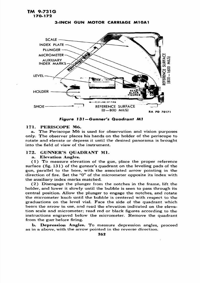
fo r 3  miles but not over 5 miles.

BEFORE OPERATION INSPECTION. Before vehicle is

road tested, perform those before-operation services,paragraph 19, necessary to determine whether the

vehicle is in satisfactory condition  to be road tested.

INSTRUMENTS  AND GAGES.

Oil Pressure Gages. Engine oil  pressure must read

.at least 11 pounds when engine is idling and 60  to 80pounds at 2,600 revolutions per minute. Stop engine

immediately when  red indicator  light comes on.Ammeter. Ammeter will show a high charging rate

for first few minutes. A high charging rate fo r extended

period with all electrical units turned off indicates adischarged battery or faulty regulator.

Voltmeter. Voltmeter must not read more than 30

volts when regulator operates properly.

Speedometer. Speedometer must register correct

speed and accumulated mileage without noise. Tachometer. The tachometer must  register accumu

lated  crankshaft revolutions.

Engine Temperature Gage. The gage should not exceed 235 F nor fall below 90 F plus atmospheric tem

perature.

Transmission Oil Temperature Gage. Oil gage should

not exceed 200 F.

Fuel Gage. Fuel  gage must register approximate

amount of fuel in tanks.Clock.  The clock must be wound,  running, and indi

cate correct time.

3 SIREN. Sound siren fo r proper tone if tactical situation

permits.

5 BRAKES.  Apply both steering brakes at slow speed totest effectiveness. Free travel  must be 4 to 8  inches.Test each brake for effective steering with moderate

66

7/29/2019 TM9_731G_1943

http://slidepdf.com/reader/full/tm9731g1943 68/284

TM 9-731G33 

ORGANIZATION PREVENTIVE  MAINTENANCE SERVICES

II8

application. Stop vehicle and apply parking brake.When steering levers are used as parking  brake, pedallock must securely hold levers in applied  position andrelease freely. When transmission parking  brake isused, lever must move freely and remain  locked  in fullyapplied position.

CLUTCH. Test free travel of pedal which   must be 3 J/2inches. Clutch must fully release and must not slip orchatter. Listen for noisy release bearing.

TRANSMISSION. Shift through entire gear range. Leverand  safety button must operate freely,  gears must shiftsmoothly, operate  quietly, and not slip out of mesh.Note any unusual noise, clashing, or hard shifting.

ENGINE. Engine must run smoothly and quietly at idlespeed of 500 to 600  revolutions per minute. Gradually

increase speed to maximum governed speed of 2,600revolutions per minute, noting any misfiring, detonation,unusual noises,  or excessive smoking.  When drivingvehicle, observe power and acceleration.

10 10 UNUSUAL NOISE. During road test listen for any unusualnoise or vibration that would indicate loose, worn or 

defective units,  or lack of lubrication.

11 11 TEMPERATURES. Stop vehicle and  feel bogie wheel androller, and idler wheel bearings for overheating.

12 12 GUN ELEVATING, TRAVERSING, AND STABILIZER  MECHANISM. Release turret lock and  gun travelling  lock.Traverse turret full  360 degrees. Elevate and depressgun with hand mechanism. All mechanism must operate

freely without binding or excessive play throughoutentire travel. Secure gun travelling lock and turret lock.

13 13 LEAKS. Stop vehicle with engine running and thor

oughly examine  bottom of hull and ground under

vehicle fo r  evidence of any leaks. Inspect hull and 

engine compartment fo r fuel, oil, or water leaks.

15 15 TRACK TENSION. Track must not bind nor whip. Proper

tension is %-inch sag between support rollers.

67

7/29/2019 TM9_731G_1943

http://slidepdf.com/reader/full/tm9731g1943 69/284

TM 9-731G33

3-INCH GUN MOTOR CARRIAGE M10A1

MAINTENANCE OPERATIONS

17 17 CRANKCASE. Stop engine and open battery master

switch. Remove engine access plate. Inspect oil pan,

engine, and connections for leaks. Drain oil pan and

refill if this service is due or oil is contaminated. When

oil is drained, do not install new oil until item 54 is

completed.54 54 ENGINE OIL FILTER. Inspect engine oil filter for loose

mounting bolts and leaks. Remove and thoroughly

clean element and install new gasket.

18 18 SIDE ARMOR. Examine front, rear and side armor, and

plates for fractures or damage that would render vehicle

unsafe for combat duty. Inspect towing shackles, lifting

eyes, and pintle hook. Make sure pintle hook latch

operates freely. Inspect fenders, exhaust deflectors, and

light guards for bent or damaged condition. Identifica

tion markings must be visible. Paint and camouflage

must meet the requirements of the tactical situation.

Tighten loose mountings and straighten bent parts.

Lubricate towing shackles, pintle hook, and latch.

19 19 BOTTOM ARMOR. Examine bottom of hull to determine

whether it is in serviceable condition. Examine inspec

tion plate and drain valves to make sure they are

properly sealed and securely mounted. Release escapehatch must operate freely and lock securely. Tighten

engine inspection plate securely. Lubricate escape hatch

lock mechanism.

20 20 DIFFERENTIAL AND FINAL DRIVES. Examine housings

for fractures, leaks, or loose attaching bolts. Drain dif

ferential and/or final drive housings when transmission

oil is to be changed. See item 78.

20

21 21

Tighten. All mounting and attaching bolts should be

tightened securely.

TRACKS. Examine tracks for loose, worn, or missingconnectors and wedges; also for worn, damaged, or dead

blocks. Inspect tracks for proper tension. Tighten all

wedge nuts securely. Replace unserviceable blocks,connectors, or wedges. Adjust track so that it is not

too tight and does not sag more than three-fourths inch

between support rollers.

7/29/2019 TM9_731G_1943

http://slidepdf.com/reader/full/tm9731g1943 70/284

TM 9-731G33

ORGANIZATION PREVENTIVE MAINTENANCE SERVICES

f 5c o

21 * Serve. Remove tracks on each third 100-hour main 

tenance service (par. 129). Thoroughly inspect all

parts covered in items 21, 22, 23, 24, and 25.

22  22  IDLERS. Examine bracket for fracture or loose or miss

ing attaching bolts. Spindle clamp and  locking collar

must  be securely locked. Inspect idler wheel for dam 

age, bearing, or bearing  seal failure, missing lubrication

fittings, or loose bearing  cap. Tighten all attaching

bolts, spindle clamp bolts, bearing cap bolts, and locking

collar.

22 ^Bearings. Bearings must be thoroughly tested for

failure, excessive wear, or looseness by using pry bar on

wheel when track is removed at  every third 100-hour

preventive maintenance service.

23 23 BOGIES. Examine bogie bracket  for fractures or  loose

mounting. Inspect bogie arms, levers, gudgeons, spring

seats,  and rubbing plates for fractures, excessive wear,

or looseness. Volute springs are unserviceable if two

or more coils contact lower spring seat.

23 Tighten. All assembly and mounting bolts must be

tightened securely.

24 24  BOGIE WHEELS AND ROLLERS. Inspect bogie wheels for

broken hubs, grease leaks, and missing lubrication  fit tings. Inspect rollers for loose mountings,  breaks, or

missing lubrication fittings. Inspect track skids for loose

mountings or excessive wear. Examine all bogie wheel

tires  for scoring, excessive wear, or blow-outs. Raise

bogie wheels using bogie lift  (par. 128). Rotate wheel

to detect worn, broken, or inadequately  lubricated bear

ings and test  for end play. Track must be  connectedwhen making this test.

24 * Serve. Raise tracks free of support rollers. Rotate

rollers to detect worn, broken, or inadequately lubri

cated bearings and test for end play. Make this .test

before track is connected at each third 100-hour pre

ventive  maintenance service. Tighten all assembly and

mounting bolts securely.

69

7/29/2019 TM9_731G_1943

http://slidepdf.com/reader/full/tm9731g1943 71/284

TM  9-731G 33

3-INCH GUN  MOTOR  CARRIAGE M10A1

*-25 25 SPROCKETS.  Examine sprockets  for fractures, exces

sively  worn or broken teeth, or loose attaching bolts.

Inspect hub for grease leaks, loose attaching bolts, orfractures.  Tighten all  attaching bolts securely.

25 ''Serve. Remove track at each third 100-hour pre 

ventive maintenance service (par. 129).  Test track

drive sprocket shaft bearings for excessive wear, end 

play, or failure, by working hub  with pry  bar.  Reverse 

or replace worn or damaged sprockets.

27  27 TOP  ARMOR. Examine all top hull and turret  armor

for fractures  or  damage that would render vehicle un

safe  for combat  duty. All covers, grilles, and hatches

must open freely and lock securely.

28 28 FILLER  COVERS AND CAPS. All filler cap covers must

open and close freely and have lock pin attached to 

chain. Examine all  filler caps for crossed threads, leak

ing gaskets or plugged vents.

30 ENGINE REMOVAL. When condition indicates engine isno longer serviceable and specific orders are given by a

higher echelon, the  engine may be removed  according

to procedure  given in paragraph 37 b.

43 43 AIR CLEANERS. Remove  air cleaners and disassemble.Inspect all gaskets and  seals for serviceability and

bodies for evidence of leaks. Clean elements and thor

oughly dry. Clean oil reservoir and refill with seasonal

grade engine oil to "FULL" mark on body.

44  44 CARBURETORS. Inspect to  see that  they are securely

mounted, not  leaking, and  that all linkage and  springs

are properly connected.

46  46 CYLINDER HEADS AND  GASKETS. Examine cylinder

leads for cracks, oil, water, or compression leaks around

studs or gaskets. Cylinder heads will not be tightened

unless there is definite evidence  of  looseness or leaks. 

Tighten cylinder heads or replace gaskets as  needed.

31  VALVE MECHANISM. Remove camshaft housings and

examine camshafts and  push rods  for good condition

70

7/29/2019 TM9_731G_1943

http://slidepdf.com/reader/full/tm9731g1943 72/284

TM 9-731G33

ORGANIZATION PREVENTIVE MAINTENANCE SERVICES

8 ..II l!-and adequate lubrication. Valve clearance is not ad

justed by the using arms. Inspect cover gasket for

serviceability.

32 SPARK PLUGS. Remove all plugs and examine elec

trodes for pitting, burning, and gap setting of 0.011 inch

to 0.014 inch. After cleaning, replace any spark plug

that is unserviceable or requires gap adjustment.

33 COMPRESSION TEST. Test engine compression in each

cylinder. Readings for all eight cylinders must not  be

below 155 pounds. Record readings in space provided

on War Department Form No. 462. Normal compres

sion  is 155 to 180 pounds at cranking  speed. Cylinders

showing above 180 pounds indicate an  excessive

amount of carbon. Variation of 15  pounds between

cylinders is permissible.

34 34 GENERATORS AND STARTER. Examine generators and

starter for loose mounting bolts or loose electrical con

nections.

34 Clean. Remove generator cover band and inspect for

worn brushes, brush spring tension,  dirty or scored

commutator. Clean commutator if required. Tightenall mounting bolts and electrical connections.

37 37 MAGNETOS. Examine for security of mounting and

good condition. Note whether there is any evidence of

oil leaks at mounting pads. Breaker point gap must be

0.016 inch. The points must be free from oil or grease

and be in proper alinement. Pitted points must be 

replaced.

45 45 MANIFOLDS. Examine exhaust manifold, intake housing 

for loose mounting bolts or gasket leaks.

49 49 WATER PUMP, FANS, AND SHROUDS. Examine water

pump, gaskets, and connections for loose mounting bolts

and leaks. Inspect fans and  shrouds for alinement and

loose attaching bolts. Tighten bolts and replace gaskets

as needed.

71

7/29/2019 TM9_731G_1943

http://slidepdf.com/reader/full/tm9731g1943 73/284

TM 9-731033 

3-INCH GUN MOTOR CARRIAGE M10A1

§1

53 53 FUEL  TANKS AND PUMP. Make sure fuel tanks, valves,

lines, tubes, and connections are tight and  securely

mounted. Inspect these items for leaks. Examine fuel

pump fo r loose mountings or leaking gaskets. Replace

gaskets and tighten as necessary.

53 Fuel Tanks and Pump. Drain tanks to remove any

sediment or water.

55 55 FUEL FILTER. Inspect filter for loose mounting and

leaks. Clean the filter element and bowl.  Replace gaskets and tighten loose mountings and connections

required.

as

57 57 EXHAUST PIPES. Inspect exhaust pipes to see that all

connections are tight; that there are no leaks; and  that

units are securely mounted.

58 58 ENGINE MOUNTINGS.  Inspect all engine mountings for looseness and tighten if required.

48 48 CLUTCH ASSEMBLY. Examine clutch housing for loosemountings and cracks. Examine all linkage for pres

ence of cotter keys and return spring. Free travel must

be 3Va inches.

51 51 ENGINE COMPARTMENT. Inspect engine compartmentand all controls and linkage, making sure they are clean

and in serviceable condition.

51 Clean. Clean engine compartment thoroughly and

when engine is removed, repaint if necessary.

60 60 FIXED FIRE EXTINGUISHER SYSTEM. Examine all lines,connections, nozzles, and controls to see that they are

tight and securely mounted. Nozzles must be intact and

free from obstructions. Cylinders must be removed andweighed to make sure they are fully charged. Operate

remote controls with cylinders removed to see that they

have sufficient travel and work freely. Lubricate pul

leys, cables, and mechanisms as needed.

61 61 ENGINE INSTALLATION. When the engine is removed at

specific order  given by a higher echelon,  it must be

installed according to procedures given in paragraph

72

7/29/2019 TM9_731G_1943

http://slidepdf.com/reader/full/tm9731g1943 74/284

TM 9-731G33

ORGANIZATION PREVENTIVE MAINTENANCE SERVICES

!i 37 b. Make certain all fuel, oil, water lines, and various

controls are securely tightened and radiator and crank-

case are filled before starting engine.

62 62 RADIATOR. Examine all water tubes, hoses, and connec

tions to see that they are tight and securely mounted.

Examine radiator core to see  there are no leaks. Exam

ine water for contamination, rust, or scale. Remove all

accumulated dirt from radiator cooling surfaces. Test

antifreeze to make sure protection is adequate for pre

vailing temperatures  and  record in space provided on

War Department Form No. 462.

63 63 BATTERIES. Clean  and dry exterior of batteries and

inspect for cracks and leaks. Clean, tighten, and grease

terminals. Make sure all electrical connections and bat

tery clamps are tight. Take hydrometer reading of each 

call. Normal reading is 1.275. Report reading if 1.225

or less. Make high rate discharge test on each cell.

Report differences of more than 30 percent between

cells. Record  hydrometer and discharge readings in

space provided on War Department  Form 462. Add

clean water to each cell as required to raise level of •electrolyte to one-fourth inch above top of plates. Bat

tery cover must be securely fastened.

64 64 ACCELERATOR. Make sure accelerator pedal and link

age has all cotter pins in place, is securely mounted and

lubricated, and operates throughout full limit of travel

without binding.

65 65 STARTER. Operate starter to make sure it engages freely

and develops adequate cranking speed without un

usual noise or grind.

66 66 LEAKS. Inspect all units serviced in the engine com

partment for evidence of any fuel, oil, or water leaks

while the engine is running. Tighten if required. Replace

gaskets and other parts if necessary.

68 68 GENERATOR REGULATORS. Inspect mountings and elec

trical connections to see that they are tight. Regulators 

must be properly grounded.

73

7/29/2019 TM9_731G_1943

http://slidepdf.com/reader/full/tm9731g1943 75/284

TM 9-731G33

3-INCH  GUN MOTOR CARRIAGE M10A1

I:

68 Serve. Make voltage and amperage tests using low

voltage tester to determine proper functioning of all

regulators.

69 ENGINE IDLE. Run engine at idling speed. Tachometer

must read 500 revolutions per minute. Listen to exhaust

fo r indication of misfiring or uneven operation. Adjust

idle as required.

70 70 THROTTLE  SYNCHRONIZATION. The throttle connecting

rod must be adjusted so that with engine stopped both

throttles are against the stops on both carburetor

adapters. Adjust and tighten linkage as necessary

(par. 56).

71 71 FIGHTING  COMPARTMENT. Inspect fighting compart

ment making  sure it is clean and free from expended

materiel and that painted surfaces are  in good condition

and clean. All fighting compartment stowage boxes,racks, brackets, and equipment must be in proper place,in serviceable condition, and securely mounted.

56 56 TRANSMISSION OIL COOLER. Inspect lines, hoses, con

nections, and core for leaks and loose mountings. Air-cooling fins must be kept clean.

72 72 TURRET.securely.

position.

Platform doors  must open freely and lockAll seats must operate freely and lock in

86 86 ELECTRICAL WIRING. Inspect all wiring, conduits, ter 

minal boxes, and electrical connections. They  must be 

tight, securely mounted, and in serviceable condition.

See that all circuit breakers are closed.

ARMAMENT

126 126 GUNS. The turret must operate through entire 360

degrees without bind or excessive backlash. Hand brake

must operate effectively. Elevate and depress gun by

hand mechanism. It must operate freely without bind

or excessive backlash under positive control  throughout

entire limit of travel. Both manual and electrical firing

controls must operate with positive action and all con 

nections and mountings must be tightened  securely.

74

7/29/2019 TM9_731G_1943

http://slidepdf.com/reader/full/tm9731g1943 76/284

TM 9-731G33

ORGANIZATION PREVENTIVE MAINTENANCE  SERVICES 

128 128 A. A. GUN MOUNT. Install gun  mount in turret bracket.

Mount must move freely in all directions without bind 

ing. Lubricate as required.

129  129  SPARE GUN BARRELS AND  PARTS. Inspect spare gun

barrel to see that it is serviceable and properly stowed.

Replace all expended armament spare parts.

84  84 COMPASS. Inspect compass to see that it is securely

mounted, contains sufficient fluid, and is in serviceable 

condition.

73 73 PERISCOPES. All mounts must pivot or rotate freely

without binding. All serviceable  periscopes  must becleaned and expended units or heads replaced.

74 74 CLUTCH PEDAL. Clutch pedal height must be 16  inches,

measured vertically, from top edge of pedal pad todriver's seat floor plate. Free pedal travel must be 3 Va 

inches. Slowly depress pedal to   see that there is  nobinding in  linkage.

75 75 BRAKES.  Steering brake levers must have 4 to   8 inches

free  travel and be parallel as shoes  contact drums.

When steering levers are  used as parking brake, pedal

lock must securely hold levers in applied position and

release freely . When transmission parking brake is used, lever must move  freely and remain locked in

fully applied  position. Adjust and  tighten linkage as

required. Replace brake shoes when road test or inspec

tion reveals either the steering or parking brake lining 

is no longer serviceable (par. 123 e and par. 124 b).

77 77 DIFFERENTIAL AND BREATHER. Inspect all  differential

seals and  gaskets in driver's compartment for evidence 

of leaking. Examine  all mounting bolts  for looseness.Tighten as necessary. Breather  must not be clogged. Remove breather and clean.

78 78 TRANSMISSION AND BREATHER. Inspect all transmis

sion  seals and gaskets for evidence of  leaking. Examine

all attaching bolts for looseness. Tighten  when neces

sary. Breather must not be clogged. Remove breather

and clean.

75 

7/29/2019 TM9_731G_1943

http://slidepdf.com/reader/full/tm9731g1943 77/284

TM 9-731G33

3-INCH  GUN MOTOR CARRIAGE M10A1

80 80 TRANSMISSION CONTROLS. Examine for worn or loose 

linkage. Safety button  must operate freely without

binding.  Tighten and lubricate when necessary.

81 81 PROPELLER SHAFT. Test propeller shaft for run-out and

inspect welds.  Inspect universal joint flange bolts for

looseness. Inspect universal joints for wear and greaseleaks. Tighten bolts and lubricate when necessary.

Housing bolts must be tight and covers securely fas

tened.

85 85 LIGHTS AND SWITCHES. With all light switches in "ON"

position, inspect all lights to see that they are operating-

properly, clean and securely mounted, and go out when

switches are turned off. Inspect  all switches, making 

sure all connections and mountings are tightened se curely.

TOOLS AND EQUIPMENT

130 130 TOOLS AND EQUIPMENT. Inspect all tools and  equip

ment to make certain they are in serviceable condition

and properly stowed in quantities shown on the current,

"On Vehicle  Materiel List."

134 134  DECONTAMINATOR. Shake to see that it is full and lookat date  on tag to see that charge is not  more than 90

days old. Recharge if required.  Fasten securely in

place.

135 135 PORTABLE FIR E EXTINGUISHERS. Remove and weigh

extinguishers to make sure they are fully charged (par.

138). Replace with fully charged units if necessary. 

Fasten securely in place.

136 136 PUBLICATIONS AND FORM  No. 26. See that the "On

Vehicle Materiel List" and  all publications and  forms

listed  therein and Standard Accident  Form No. 26 are

legible and properly stowed.

137 137 VEHICLE LUBRICATION. Check  lubrication of  entire

vehicle. On any unit where disassembly was necessary

for inspection purposes, lubrication must be performed

7/29/2019 TM9_731G_1943

http://slidepdf.com/reader/full/tm9731g1943 78/284

TM  9-731G33

ORGANIZATION PREVENTIVE MAINTENANCE SERVICES

$

•II

unless the vehicle is to be deadlined for repair of that 

unit. Lubricate all points of vehicle in accordance with

instructions in   this manual, War Department Lubrica

tion Guide (figs. 13 and 14), current lubrication bulle

tins, or directives, and the following instructions: Use

only clean lubricant and keep all lubricant containers

covered; before applying lubricant, clean lubrication fitting or plug; replace missing or damaged fittings, lines,

plugs, or vents. On unsealed bushings or joints, the lubri

cant should be applied until  it appears at openings. On

units provided with lubricant retainer seals, do not force

excess lubricant past seals. Drain oil from engine, oil

tanks, oil pump, transmission, transfer case, differential,

and final drives while warm. Refill units to correct

level as soon as draining is completed so ufiits will not

be operated without lubricant. The "COLD" oil level,as marked on the oil level indicator in transmission, is

the level desired  and if conditions make it necessary

to check the level when hot with oil foaming, level may

be above level line marked "HOT." Do not apply more

than specified amount of lubricant to generator or

starter. To do so, may cause a failure of the unit. Wipe

off excess lubricant that may  soil clothes and equip

ment, or detract from the  vehicle's appearance. Parts

or assemblies that have been lubricated while dis

assembled for inspection, gear cases that have been

drained  and refilled  as mandatory items in the proce

dures, and those parts that have been indicated in the

procedures for special lubrication may be omitted from

the general lubrication of the vehicle.

138 138 MODIFICATION. The organizational records must be

reviewed to make certain that all Field  Service Modifi

cation Work Orders pertaining to the vehicle have been

completed.

139 139 FINAL ROAD TEST. Repeat items 2 to 15 inclusive,

paying particular attention to those units on which work

has been performed to make certain they have been

restored to first-class operating condition. Correct any

deficiencies found during the final road test.

7/29/2019 TM9_731G_1943

http://slidepdf.com/reader/full/tm9731g1943 79/284

TM  9-731G 34

3-INCH GUN MOTOR CARRIA GE M10A1 

Section X

ORGANIZATIONAL TOOLS AND EQUIPMENT

Paragraph 

Allocation  of tools and equipment....................... 34

a. The tools and equipment included  in this  section, together with

the vehicular tools listed in section VII, provide the using arms withnecessary tools and equipment  for servicing the vehicle.

Sets.

Federal   Stock

St andard Tool  Sets Number

Tool-set, motor vehicle mechanics'.  .............. 41-T-3538Tool-set, blacksmiths' No. 2  ..................... 41-T-3515Tool-set, pioneer equipment, motor vehicle

Set No. 1.................................. 41-T-3539-5Tool-set, welders' ..........................:..  41-T-3555Tool-set, unit equipment, second echelon

Set No. 1.................................. 41-T-3545-10

Tool-set,  unit equipment, second echelon

Set No. 2 .................................. 41-T-3545-11

Tool-set, unit equipment, second echelon 

Set No. 3 .................................. 41-T-3545-12

Tool-set, unit equipment, second echelon

Set No. 4................................... 41-T-3545-13

Tool-set, unit equipment, second echelon

Set No. 5 .................................. 41-T-3545-14 

Tool-set, unit equipment, second echelon

Set No. 6..................................  41-T-3545-15

Tool-set, unit equipment,  second echelon 

Set No. 7..................................  41-T-3545-16

Tool-set, unit equipment, second echelon

Set No. 9 .................................. 41-T-3545-18

78 

7/29/2019 TM9_731G_1943

http://slidepdf.com/reader/full/tm9731g1943 80/284

TM 9-73 1G 34

ORGANIZATIONAL TOOLS AND EQUIPMENT 

c. Organization Special  Tc ols.

2Tu (XI

o  3 jt;>» £i

I

ll uO.

«£Vfrs. Mfrs. Stock X c £

Symbol Tool No. Number > i too II 

WKR  T61 41-A-18-100  2

MTM  M3-497 41-B-1586-200  4 2  4

41-B- 1586-350 4

MTM M3-3  2 2 2

MTM  M3-13 41-D-1463 1 1 1

MTM M3-41 1 1 1

MTM  M3-15 41-D-1540-500  1 1 1 

MTM  M3-14  41-D-1540-550 1  1  1

TK  7278 41-F-2997-85 1  1  1  1

MTM M3-158   1 1 1 1

MTM  M3-S  41-G-2500  1 1 1

WKR T-S  41-H-1507-50  1  1  1  1

WKR T77  41-1-115  1 1 

MTM  M3-813 41-L-1375   1  1  1

WKR  T51 41-P-1567-300 1 1

MTM  M3-133 41-P-2838 1 1 1 

MTM M3-6A  41-P-2905-65  1

MTM M3-8  41-P-2940-800 1 1  1

MTM M3-40 1 1 1

X (XFederal 0  f

Name 

Adapter, overhaul stand, use

stand  1S035 

Bolt, eye lifting, engine com 

partment top  plate 

Bolt, eye, 1-8NC-2 transmis

sion lifting 

Compressor, suspension  vo

lute spring 

Drift, bogie wheel,  bearing 

Drift, idler wheel inner bear

ing, use with W/MTM-

M3-8 puller

Drift, idler wheel inner bear 

ingDrift, idler wheel outer bear 

ing 

Fixture, track connecting 

with simplex  jack 

Gage, pair brake  linkage, 

adjusting

Guide, bogie wheel gudgeon,

installing

Handle, socket  wrench,

spark plug

Indicator, top  dead  center

and timer

Lift, bogie wheel, medium 

tank 

Plate, timing, magneto driv 

en gear shaft holder  and 

indexing 

Protector, bogie  wheel

gudgeon,  driving

Puller,  bogie gudgeon  screw

type with adapter 

A161884 

Puller, idler wheel

Puller, idler  wheel outer

bearing

79

7/29/2019 TM9_731G_1943

http://slidepdf.com/reader/full/tm9731g1943 81/284

TM  9-731G 34

3-INCH GUN MOTOR CARRIAGE M10A1

Name

Puller, slide hammer type,

bogie gudgeon

Remover, dowel, clutch and

flywheel alinement

Remover, flange clutch and

engine turner

Replacer, clutch  pilot bear

ing

Screwdriver, special, ad

justing

Sling, engine

Sling, final drive and trans

mission

Socket, screwdriver, '/a -in.

square drive (for V^-in,armor plate bolts) 

Socket, screwdriver, Vi-in.

square drive (for %-in.

armor plate bolts)

Stand, engine, overhaul 

Tool, clutch, disk alining

Tool, idler wheel installing

Wrench, box socket, suspen sion, spring compressor,

special, IVi-in. hexagon 

Wrench, box, 3-in. hexagon,

44% in. long

Wrench, cylinder head nut,

long

Wrench, cylinder head nut,

short

Wrench, drain plug, finaldrive, differential, %-in.

hexagon

Wrench, drain plug, trans 

mission

Wrench, open end, special

timing, 3A-in. •

Wrench, plug,  male, s/s-in.

hexagon

Mfrs. Symbol

WKR

WKR

WKR

WKR

WKR

MTM

STYWKR MTM

MTM

MTM

WKR

WKR

MTM

MTM

WKR

MTM

Mfre.Tool No.

T58 

T14

T78

T59

T68

M3-136

1503S

T3

M3-9

M3-2A

M3-7

T9

T29

M3-130

M3-131

T69

M3-10

Federal Stock

Number41-P-2957-33 

41-R-2377 

41-R-2380-500

41-R-2391-36

41-S-1652-500

41-S-3831

41-S-3832-72

41-S-3867-150

41-S-3867-157

41-S-4942-14

41-T-3083-75

41-T-3216-150

41-W-640-200

41-W-640-400

41-W-866-200

41-W-866-2SO

41-W-877

41-W-878

41-W-1S78-500

41-W-1960

venie le

3et

3Xu

1

1

1 11 1

1

|ompany Bn .egt. B °et or

i. O.|rew OSet

II

.

1 1 11

1 1 1 1

1 1 124

2 2

2 22

1 11 1 1

1 1 11 1 11 1 11 i 1

1 1 11 1 1

1 11 1 1

80

7/29/2019 TM9_731G_1943

http://slidepdf.com/reader/full/tm9731g1943 82/284

vi

TM 9-731G 34 

ORGANIZATIONAL  TOOLS  AND  EQUIPMENT

Nome 

Wrench, socket, bogie wheel

gudgeon nut, 2% -in. 

hexagon 

Wrench, socket, idler wheel

shaft  lock nut

Wrench, socket, spark plug,

Ford GAA  engine 

Wrench, socket, special

clutch, mainshaft nut,

2'/8-in. 

Wrench, spanner, track  sup 

port roller  lock  ring 

Wrench, spanner, track  sup 

port roller retainer

Wrench, spanner,  special 

lock, magneto driven gear

to cross shaft

Mfrs. Symbol

MTM 

MTM 

WKR 

WKR 

MTM 

MTM 

WKR 

Mfrs. Tool No.

M3-137

M3-21

T5 

T17 

M3-19 

M3-11 

T36 

Federal Stock

Number

41-W-2573-150

41-W-3336-300 

41-W-2964-248 

41-W-3260

41-W-3261 

41-W -3255-S50 

SetVehicle

Company v>*. £|

et

VI0- <n 

O  .

9 £

tooI  c £ ll 

1 1 1

1 1 1 

1 1 1 1 

1 1

1 1 1

1  1 1

1 1

81 

7/29/2019 TM9_731G_1943

http://slidepdf.com/reader/full/tm9731g1943 83/284

TM 9-731G 

35 

3-INCH  GUN MOTOR CARRIAGE M10A1

Section  XI

ENGINE 

Parag raph

General description and data...................:......  35

Engine trouble  shooting .............................. 36 

Engine replacement .................................. 37 

Engine mounts ...................................... 38 

Governor  ...........................................  39

Valve mechanism  .................................... 40 

Manifolds .......................................... 41 

Oil  pump ..........................................  42

Oil filter  ........................................... 43 

Crankcase  breather  ..................................  44

35.  GENERAL DESCRIPTION AND DATA.

a. Description. This vehicle is powered with  a  60-degree,  V,8-cylinder, 4-cycle, valve-in-head, liquid-cooled Ford tank engine. Thecylinder block and crankcase are cast enblock of aluminum with  steel,dry-type, sleeves in cylinder  bores. The  water jackets  extend the fu lllength of  cylinders. Four  overhead camshafts  are  used,  one exhaustand one  intake for each bank of cylinders. There are two  exhaust and two  intake valves  in  each cylinder. The engine is mounted at the  rearof the vehicle and supported by four brackets. The two  front brackets are mounted  on the  engine  compartment bulkhead.  The  two rear 

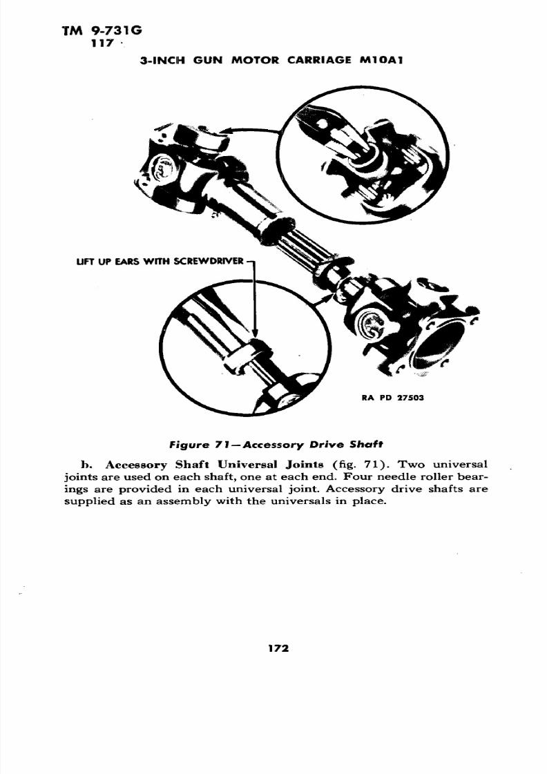
brackets  are mounted on the engine  compartment floor. Rubbermounts are used between the brackets and the engine. Two 4-cylinder magnetos are used. These  are located  at the  rear  of the  engine (fig.19), one mounted at each end of a cross  shaft driven by  gears . Thewater pump (fig. 19),  is driven  from  the end of  the  crankshaft.  Two accessory drive housings located on the side walls of the engine com partment are each driven through an  accessory drive  shaft and  universal  joints by  the accessory drive  gears in   the  engine.  Two pusher-type fans  are driven through  double V-type belts  by the  accessory

drives (par. 66). The  generators are mounted  on the forward end  ofthe  accessory drive  housings (par. 72). The  oil pump (par. 42) is  ofthe gear type.

b. Definition of Terms. The flywheel end of engine  will be  referred to as the "front"  of the engine as the engine  is mounted  in thevehicle with the  flywheel  fo rward . The terms  "right" and  "left" areused  with  reference to  the engine as  viewed from  the rear lookingtoward front of the vehicle .

82 

7/29/2019 TM9_731G_1943

http://slidepdf.com/reader/full/tm9731g1943 84/284

CO  O 

m  O  m 

MANIFOLD 

P

M

P

A

H

NPIPE 

H P

A EYE 

FA MO

U A

M

2

FC

O

CO H

E


LF

N

FR

R P

WA

FR

P

U SHAFT 

CYL

NDER 

V

N

LA

N

CLUT

R

CA

ADAPT

R

G

C

U

C

SPARK 

CARBURETOR 

S

T


Side

MA

FOLD

E 1EngineRight

P

U

Figure

D

N

B

O

FLR

C

N

OL

MANIFOLD 

POL

C PP

HPUMP 

REAR 

IN

C

O

HOUS

NG 

B A M

G

O

DRIVE 

F

L

M

C

O

R GOV

NOR 

C C

O

H RG

A

O

WA

OIL

RG

0 u 

7/29/2019 TM9_731G_1943

http://slidepdf.com/reader/full/tm9731g1943 85/284

TM  9-731G 

35-36 

3-INCH  GUN MOTOR  CARRIAGE  M10A1 

The following  data includes  the general in  formation and engine characteristics which are  frequently required  for

reference:

General: 

Make and type............ Ford  V-type,  8-cylinder, tank  engineModel  ............................................ GAA

59.02  inches longOver-all dimensions  (including clutch) 33.25 inches wide

47.78 inches high

Weight  (including all parts listed  in paragraph 45  d) ... 1,470 IbHorsepower ............................. 500  at 2,600 rpmTorque .............................. 1,050  Ib at  2,200 rpmNumber of cylinders..................................... 8 Bore ............................................ 5.4 in.

Stroke ............................................. 6  in.Piston  displacement  ............................. 1,100  cu in.Compression ratio ................................ 7.5 to  1

Directions or  rotation (viewed from rear of engine):Crankshaft ..................................... ClockwiseStarter  .................................. CounterclockwiseMagnetos (right-hand  rotor) ..................... .Clockwise

(left-hand  rotor) .................. .CounterclockwiseAccessory speeds:

Fan .................................. 1.4 crankshaft speedTachometer .......................... . y2 crankshaft speedGenerator ............................ 1.75 crankshaft speedMagneto rotor .......................... J/2 crankshaft speed

Magneto:

Make and model...................... Bosch  MJF4A307-308Breaker point gap ........................ .0.014 in.-0.16 in.Spark  plug  gap .......................... .0.011  in.-0.014  in. 

Valve clearance (nonadjustable) ............... .0.027 in.-0 .30  in.Carburetor—Make and model (2 used)  Bendix-Stromberg NA-Y5G 

Numbering of cylinders from  rear to   front:Right bank ....................................... 1-2-3-4 Left bank  ...................................... 1-2-3-4

Firing order:  1-R, 2-L, 3-R ,  1-L,  4-R , 3-L, 2-R, 4-L

Difficulty  in  determining  the  exact cause  of  enginetrouble will be encountered at times because of  the number of sources

84 

7/29/2019 TM9_731G_1943

http://slidepdf.com/reader/full/tm9731g1943 86/284

7/29/2019 TM9_731G_1943

http://slidepdf.com/reader/full/tm9731g1943 87/284

TM 9-731G36 

3-INCH GUN MOTOR CARRIAGE  M10A1

to which a given symptom may  be attributed. The best method  of

trouble shooting is to consider the possible causes and eliminate them,

one by one, starting with the most probable cause. The purpose of thisis to minimize, in so   far as possible, the time wasted in ascertaining

the source of a given trouble.

Is

Possible Cause

Battery master switch off.

Starter button circuit incomplete.

Starter button defective.

Circuit to starter incomplete.

Battery not grounded.

Open circuit in  starter.

Possib le Remedy

Turn master switch on.Tighten connections and repair

or replace wires.Replace (par. 88).

Tighten connections and repair

cable.

Clean  and tighten connections.

Replace (par. 78 b).

Is

Battery  is undercharged. Recharge or replace (par. 76 d)and correct cause.

Starter is shorted. Replace starter (par. 78 b).

Starter circuit is shorted. Repair or replace cable.

Starter drive faulty. Replace.

Starter gear on flywheel faulty. Notify ordnance maintenance

personnel.

Ignition switch "OFF." Fuel shut-off valves closed. Fuel tank empty. Engine flooded (overpriming).

Insufficient priming. Magneto ground wires shorted. No fuel in carburetor bowl. No spark at spark plugs. Ignition switch faulty. Ignition timing (engine back-

fires but does not start).

Turn "ON."Open valves.Refill tank.Place throttle in wide open posi

tion and turn engine over with

the starter five or six revolu

tions.Reprime the  engine with two or

three additional strokes.

Replace.

(Par. 36  £.)

(Par. 36 g.)

Replace (par. 48).

Time ignition (par. 46 c).

86 

7/29/2019 TM9_731G_1943

http://slidepdf.com/reader/full/tm9731g1943 88/284

WA

MA

FOLD

C

M

H

N

C

O

A

C

O

A

H

PP

E

MA

FOL

D

L

H

M

G

O

L

R

M

WA

PMP

E

IN

OL

B

O

G

G

OL

L

G

G

E

N

U

T

C

N

S

M

D

N

P

U

OL

P

D

N

PU

—————— 

C

O

N

MA

FOLD

WA

M

FO

D

R

C

O

G C

C

B

IG

TO

C

C

T

C

O

A

H

PP

0  z

RG

H

M

G

O

RG

R

M

A

O

G

C

OL

FL

OL

P

R

P

J

Figure 1

—E

n—

R

View 

7/29/2019 TM9_731G_1943

http://slidepdf.com/reader/full/tm9731g1943 89/284

TM 9-731G36

3-INCH GUN MOTOR CA RRIAGE M10A1

.2

ou.

*5>

8 s

O

88 

7/29/2019 TM9_731G_1943

http://slidepdf.com/reader/full/tm9731g1943 90/284

TM 9-731G 36

Possible Cause Possible Remedy

Fuel shut-off valves closed. Open valves.Fuel filter clogged. Clean fuel filter.Fuel lines clogged. Blow out or replace.Fuel pump faulty. Replace (par. 59 cl).Magneto ground wires shorted. Replace.Spark plug wires broken or Replace (par. 50 b).

faulty insulation.

Spark plugs shorted. Replace.Ignition switch faulty. Replace.

Magnetos faulty. Replace (par. 46 b).

Magnetos out of time. Notify ordnance maintenance

personnel.

Spark plug wires on wrong ter- Connect as shown in figure 30.minal of magnetos.

Fuel mixture too rich due to:

Carburetor float level too high. Replace carburetor (par. 52 e).

Fuel pump pressure too high. Replace fuel pump (par. 58 c).

Fuel mixture too lean due to:Engine cold. Run engine until normal tem

perature is reached.

Carburetor float level too low. Replace carburetor (par. 52 e).

Dirt in carburetor. Replace carburetor (par. 52 e).Fuel pump pressure too low. Replace fuel pump (par. 58 c).

Air leak at carburetor gasket Tighten or replace gasket,

or carburetor adapter

gasket.

Ignition trouble due to:

Magneto distributor plate Replace magneto (par. 46 b).cracked.

Spark plug wires on wrong ter- Connect as shown in figure 30.minals of magnetos.

Spark plug wires (broken or Replace (par. 50 b).faulty insulation).

Spark plug gap too wide. Replace plugs (par. 49).

89

7/29/2019 TM9_731G_1943

http://slidepdf.com/reader/full/tm9731g1943 91/284

TM  9-731G36 

3-INCH  GUN MOTOR  CARRIAGE  M10A1 

R. H. ACCESSORY  DRIVEUNIVERSAL  J OINT 

WATER  PUMCOOLING   SYSTEM  DRAIN

RA   PD 27273 

f igure  21 —Engine —Viewed  Through  the  Rear Door 

Poss ib le Cause Poss ib le Remedy

Engine valves due  to:

Insufficient push  rod  clear  Notify ordnance  maintenanceance. personnel.

Sticky  valve guides,  broken Notify ordnance  maintenancevalve  springs,  and  valve personnel.seats  leaking.

Water  low. Refill.Air  flow  restricted  through  radi Clean  (par. 33  a (5)).

ator core.

Loose  fan  belts.  Adjust (par.  66  b).Engine operating with  late spark. Time  ignition  (par.  47).Therm ostat  faulty.  Replace  (par.  68  J>). 

90 

7/29/2019 TM9_731G_1943

http://slidepdf.com/reader/full/tm9731g1943 92/284

7/29/2019 TM9_731G_1943

http://slidepdf.com/reader/full/tm9731g1943 93/284

TM 9-731G 36

3-INCH GUN MOTOR

1. Lack of Power.

Poss ib le Cause

Spark plug  gap too wide. Track suspension too tight. Track suspension dirty. Ignition timing late. Low compression. Valve timing. Clutch  slipping.

Oil supply low. Over diluted oil. Faulty oil pressure regulator. Excessive bearing clearance.

Noise. 

CARRIA GE M10A1

Po ss ib le Remedy

Replace spark plugs  (par. 49).Adjust (par. 129 b).

Clean.

Time  ignition  (par. 47).

Notify ordnance maintenance 

personnel.

Notify ordnance maintenance

personnel.

Adjust (par. 115 b, c,  d).

Replace (par.  115 g).

Refill.

Change  oil.

Notify ordnance maintenance

personnel.

Notify ordnance maintenance

personnel.

Valve mechanism and camshaft idling noise due to:NOTE: Camshaft backlash noise below 500 revolutions per minute

is not to be considered abnormal.

Broken or scored push  rod.

Broken valve springs.

Connecting rod bearing knock.

Crankshaft main bearing knock.

Notify ordnance

personnel. 

Notify ordnance

personnel.Notify ordnance

personnel.

Notify ordnance

personnel.

Engine pinging or spark knock due to:

maintenance 

maintenance

maintenance

maintenance

maintenancexcessive carbon formation.

Ignition timing too early.

Wrong  type spark plug. 

Low octane fuel.

Spark fails  to retard due to

broken magneto governor

springs or sluggish action

of governor weights.

Notify ordnance

personnel.

Time ignition  (par. 47).

Replace with correct type (par.

49).

Drain and refill with correct

quality (par. 4 i).Notify ordnance maintenance

personnel,

92

7/29/2019 TM9_731G_1943

http://slidepdf.com/reader/full/tm9731g1943 94/284

TM 9-731G 36-37

ENGINE

RA  PD 27694

Figure 23—Removing  Right Door

(1)  TURN BATTERY MASTER SWITCH  "OFF."

(2) REMOVE DOORS AND COVERS FROM  THE ENGINE COMPART

MENT. Remove five cap screws which secure each door to top of hull

and lift doors from vehicle (figs. 23 and 24), with a chain fall or hoist.

Remove the cap screws which hold rear cover plate to top of hull and lift from hull with chain fall or hoist (fig. 25). Remove cap screws

which hold front cover to top of hull and lift cover from hull.

(3) OPEN  REAR DOOR OF  THE ENGINE COMPARTMENT. Remove 

the three cap screws which hold door closed. To open this door all the

way, raise radiator air baffle and allow it to rest on top of door after

door is open.

(4) REMOVE ENGINE COMPARTMENT FLOOR PLATE. Remove lock

wires from  cap screw heads which hold floor plate to hull. Remove

cap screws leaving one at each corner of  floor plate. Place a jack atcenter of the plate and remove remaining cap screws, then lower floor

plate with jack.

(5) DRAIN  COOLING SYSTEM. Remove drain plug at bottom ofwater pump (fig. 21) and drain cooling system.

(6) DRAIN ENGINE OIL. Remove drain plug at bottom  of engine

oil pan and drain  oil (a  container holding 8 gallons or more is re

quired).

93

7/29/2019 TM9_731G_1943

http://slidepdf.com/reader/full/tm9731g1943 95/284

TM 9-731G

37

3-INCH GUN MOTOR CARRIAGE M10A1

~~\-*

PD 27695

(7) REMOVE OIL FILLER PIPE (fig. 21). Remove three nuts which

hold oil filler  pipe to engine oil pan. Remove filler pipe.

(8) REMOVE WATER PUMP AND RADIATOR EXPANSION TANK.

Remove four nuts securing water pump to engine and disconnect water

pump hose. Remove water pump (par. 65 c). Remove cooling system expansion tank and hose (par. 69 b).

(9) REMOVE MISCELLANEOUS ELECTRICAL CONNECTIONS. Discon

nect the degasser wires from carburetors (fig. 37); disconnect tem

perature gage wires and degasser conduit from engine. Disconnect

starter cable at starter. Disconnect oil level indicator wire on left side

of engine oil pan. Disconnect  oil pressure gage connection at  right

rear end of engine oil pan. Disconnect ground wire (running from each

magneto to the ignition switch) at each magneto (fig.  30); then with

two short lengths of wire, ground the ground wire terminal of each

magneto to cover retainer screws (fig. 30).  This will prevent pos

sibility of engine starting in the event it is turned over.

(10) REMOVE INLET AND  OUTLET CONNECTIONS FROM RADIATOR.

Loosen clamps and remove two top radiator hose. Remove four cap

screws from radiator upper and lower water connections. Removeconnections (including thermostat and gasket).

(11) REMOVE FAN BELTS. To remove fan  belts, loosen four bolts

94

7/29/2019 TM9_731G_1943

http://slidepdf.com/reader/full/tm9731g1943 96/284

TM 9-7316 37

ENGINE 

RA PD 27696 

Figure 25—Removing Engine Compartment Rear Cover Plate 

securing each accessory drive housing to hull (fig. 45). Raise housings

to provide slack for belts and remove belts.

(12) REMOVE FAN AND SHROUD ASSEMBLIES AND ACCESSORY

SHAFTS. To remove fan and shroud assemblies and accessory shafts,

remove six bolts holding each fan shroud in place. Remove each fan

and  shroud assembly from  engine compartment. Remove the four

bolts from flanges of universal joint at each end of accessory drive

shaft. Remove accessory shafts.

(13) DISCONNECT  THE TACHOMETER  CABLE AND FIRE EXTIN

GUISHER  NOZZLES. Disconnect tachometer cable from tachometer

drive  unit located on left-hand camshaft housing. Remove pipe con

nections from upper fire extinguisher nozzles on  right- and  left-hand

side of engine compartment. Remove two cap screws from each fire

extinguisher nozzle bracket. Remove nozzles and brackets.

(14)  DISCONNECT FUEL AND PRIMER  LINES. Shut  off fuel valves

(fig. 9). Disconnect fuel line from fuel pump. Disconnect primer lineat left side of forward carburetor, and remove primer lines  running

to each intake manifold.

(15 ) DISCONNECT THROTTLE ROD. Disconnect and remove throttle 

control rod running from throttle cross shaft on bulkhead to throttle

control bracket in  center of the engine (fig. 39).

(16) REMOVE AIR CLEANERS AND TUBES. Remove the two air

cleaners and tubes (par. 55 c).

95

7/29/2019 TM9_731G_1943

http://slidepdf.com/reader/full/tm9731g1943 97/284

TM 9-731G37

3-INCH GUN MOTOR CARRIAGE M10A1

ENGINE LIFTING SLING

USE CRANK TO TILT ENGINE

RA PD 27980

LIFTING EYES

Lifting Sling

(17) DISCONNECT REAR UNIVERSAL JOINT AND CLUTCH THROW-

OUT CLEVIS. Lift the cover over propeller shaft rear universal joint

and remove eight bolts which connect universal joint to clutch shaft

flange (fig. 35). Remove clevis pin from clutch release arm (fig. 18).

(18) REMOVE EXHAUST PIPES AND DISCONNECT ENGINE MOUNTSFROM SUPPORT BRACKETS. Remove six bolts that secure exhaust pipes

to exhaust manifolds on each side of engine. Remove exhaust pipes.

Remove four bolts from both engine rear support brackets and two

rear bolts from both engine front support brackets. Remove plates

from clutch housing cover which are directly in front of engine front

support brackets; then remove two front bolts from both support

brackets.

(19) REMOVE ENGINE FROM HULL (fig. 26). Attach engine, sling

96

7/29/2019 TM9_731G_1943

http://slidepdf.com/reader/full/tm9731g1943 98/284

7/29/2019 TM9_731G_1943

http://slidepdf.com/reader/full/tm9731g1943 99/284

TM 9-731G37

3-INCH GUN MOTOR CARRIAGE M10A1

pump. Connect primer line at  left side of forward carburetor  and

primer lines running to each intake manifold.

( 7 )  CONNECT TACHOMETER CABLE AND FIRE EXTINGUISHER NOZZLE. Connect tachometer cable to tachometer drive unit located on

left-hand camshaft housing. Install upper fire extinguisher nozzles and

brackets on both sides of engine compartment. Connect fire extin

guisher pipes to nozzles.

(8) INSTALL FAN AND SHROUD  ASSEMBLIES AND ACCESSORY

SHAFTS. Place fan and shroud assemblies in position in front of radi 

ator. Place a new felt gasket between shroud and holding plate. Place

a rubber bushing and collar in mounting holes, and install  six bolts,securing each fan shroud to hull plate. Place right and  left accessory

drive shafts in position, and install four  bolts in flanges of universal

joint at each end of accessory drive shafts.

(9) INSTALL FAN BELTS. To install the fan belts, loosen four bolts

securing each accessory drive housing to hull (fig. 45). Raise housings

to provide slack for belts. Install belts and adjust to proper tension 

(par. 66 b).

(10) INSTALL INLET AND  OUTLET CONNECTIONS TO RADIATOR.Install  four cap screws  in radiator upper and lower water connections

to radiator (including thermostat and gaskets). Install two top radi

ator hose and tighten clamps.

(11) CONNECT MISCELLANEOUS ELECTRICAL CONNECTIONS. Con

nect oil pressure  gage connection at right rear  end of engine oil pan.

Connect oil level indicator wire to oil level indicator on  left side of 

oil pan. Connect starter  cable to starter. Install degasser conduit on

engine and connect degasser  wires to degasser connections on car

buretors. Connect temperature gage, and boil signal wires to engine

units. 

(12) INSTALL WATER PUMP AND RADIATOR EXPANSION TANK.

Install water pump with gaskets on four studs on engine and secure

with four fiber insert nuts. Install the two hose running from water

pump to radiator lower water connection and tighten hose clamps.

Install expansion tank (par. 69 b).

(13) INSTALL OIL FILLER PIPE. Install oil filler pipe and secure

it with three fiber insert nuts.

(14) FILL ENGINE OIL PAN. Install drain plug in bottom of engine

oil pan and fill with 8  gallons of specified  oil.

(15)  FILL COOLING SYSTEM. Install drain plug in water pump (fig.

21) and fill cooling system to level of the petcock in radiator upper

water connection (fig. 46). 

(16) INSTALL ENGINE FLOOR PLATE. Place  a jack at the center

98

7/29/2019 TM9_731G_1943

http://slidepdf.com/reader/full/tm9731g1943 100/284

TM 9-731G

37-38

ENGINE

of the floor plate  and raise the plate against the bottom of the hull.

Install a cap screw at each corner of the plate. Remove the jack and

install the remainder of cap screws and secure with locking wires.

(17) CLOSE  AND FASTEN REAR DOOR  OF ENGINE COMPARTMENT.Raise the air baffle and close the engine  compartment rear door.

Install and tighten the  three cap screws securing the door to rear of

hull.

(18) INSTALL DOORS AND COVERS ON ENGINE COMPARTMENT.

Place the front cover on the engine compartment and install the cap

screws. With a chain fall or hoist place the rear cover (fig. 25) in posi

tion and install the cap screws. With a chain fall or hoist, place the right and the left doors in position (figs. 23 and 24), and install the

cap screws.

(19) TURN BATTERY MASTER SWITCH ON, START ENGINE, AND

CHECK FOR OIL OR WATER LEAKS.

ENGINE (figs. 17 and 18).

The  four engine mounts used to support the  en 

gine provide flexible rubber installation between the engine and its

mounting brackets.

(Front)

(1) REMOVAL. Remove engine compartment floor plate (par. 37

a (4)). Place a jack under  front of the engine oil pan, using  a wood

block between the pan and jack. Lift engine enough to take weight off

engine  mounts. Remove the four bolts which hold the mount to the

support bracket. Two of these bolts are accessible through the inspec

tion opening in the bulkhead and two through the engine floor plate

opening. Remove the long bolt which holds the halves of the mounttogether. Remove the four nuts which hold the mount to the clutch

housing. The two  rear nuts are accessible through the engine floor

plate opening, and the two front nuts through the inspection opening

in the bulkhead.

(2) INSTALLATION. To reinstall engine  front mounts,  reverse the

sequence of the steps of the removal procedure.

(Rear)

(1) REMOVAL. Remove  engine compartment floor plate (par. 37

a (4)). Place a jack under rear  of the engine oil pan, using a wood

block between the pan and jack. Lift the engine enough to take weight

off the engine mounts. Remove  the four bolts which hold  the  mounts

to the support bracket. Remove the four nuts which hold the mount

to the engine. Remove the mount.

(2) INSTALLATION. Reverse  the sequence  of the steps in the re

moval procedure.

99

7/29/2019 TM9_731G_1943

http://slidepdf.com/reader/full/tm9731g1943 101/284

TM 9-731G39-41

3-INCH GUN MOTOR CARRIAGE M10A1

The speed of the engine is regulated and limited

by the use of additional dual throttle plates located in each of thecarburetor adapters directly under each carburetor. These carburetor

adapter throttles are connected by a rod, which in turn is connected

to the governor located at the rear of the right-hand camshaft housing

and is driven by the right-hand intake camshaft. With the engine

idling, these governor-actuated throttles are in the wide-open position.

As the engine speed is increased the action of the governor partially

closes the throttles, thus limiting the maximum engine speed to ap

proximately 2,600 revolutions per minute under full load. All main

tenance on the governor must be referred to ordnance maintenancepersonnel.

The governor throttle connecting link

should be adjusted by means of the clevis on the forward end so that

with engine stopped, both throttle levers are against the stop on both

carburetor adapters (figs. 19 and 20).

a. Two inlet and two exhaust valves are provided for each cylinderand are operated by overhead camshafts, two in each cylinder head.

One shaft operates the intake valves and the other the exhaust valves.

Special nonadjustable valve push rods are used. The clearance of

0.027 to 0.030 inch is established during manufacture or overhaul, and

since this clearance is established cold and is greater than the maxi

mum normal expansion of the parts, it should require no attention by

the using arms. Both intake and exhaust valve ports are provided with

steel alloy insert seats.

The intake manifolds are cast integral with the

cylinder heads and are open at each end. Carburetor adapters are in

stalled between the carburetors and the intake manifolds. These

adapters are likewise connected to the exhaust manifolds which heat

the fuel air mixture as it comes from the carburetors. These adapters

each contain two butterfly valves operated by the engine speed gov

ernor (par. 39).

(1) DESCRIPTION. Two exhaust manifolds are used, one attached

to each cylinder head. The end of each manifold is attached to the

carburetor adapter housing by means of a connecting pipe.

(2) EXHAUST MANIFOLD REPLACEMENT. Remove the three cap

screws from the upper flange and the three bolts from the lower flange

of the carburetor heater pipe which connects the ends of the exhaust

manifold to the carburetor adapter. Remove the 6 bolts at the center

100

7/29/2019 TM9_731G_1943

http://slidepdf.com/reader/full/tm9731g1943 102/284

7/29/2019 TM9_731G_1943

http://slidepdf.com/reader/full/tm9731g1943 103/284

TM 9-731G43-44

3-INCH GUN MOTOR  CARRIAGE M10A1

MANUAL TURNING NUT

MANUAL TURNING NUT REVERSED

Figure 27—Oil f i l ter

minutes, to see if it has rotated. After check is made, replace manual

turning nut in original position, and secure with lock  wire. If filter

nut fails to turn, remove unit from engine for examination or replace

ment.

Remove engine compartment floor

plate (par. 37 a (4)). Remove six nuts securing filter to oil pan and 

remove filter unit. Install filter unit and secure filter to oil pan with

six nuts. Install engine compartment floor plate (par. 37 b  (16)).

Remove filter (par. 43 c). Clean filter element by 

washing in dry-cleaning solvent. Turn element by  means of manual 

turning nut while cleaning. Continue to rotate element in solvent until

all foreign material has been  removed. When thoroughly clean, allow

to dry. NOTE: Do not blow air on the element.

(fig. 28).

The crankcase breather is located directly above

the  water pump, accessible either from above or through the  engine

compartment rear door (fig . 21). Figure  28 is an exploded view of

the crankcase breather and shows the cover and the filter element.

102

7/29/2019 TM9_731G_1943

http://slidepdf.com/reader/full/tm9731g1943 104/284

TM 9-731G44 

ENGINE

FILTER

BREATHER

TIMING  SLOT

PD 27539 

f igure 28—Crankcase Breather

To remove filter  element for clean ing, release  the two holding clips and lift  off cover. Lift off  the filterelement. The filter should be cleaned by  washing in dry-cleaning  solvent. Blow  out with compressed air, and when  dry, dip  in seasonalgrade engine oil. Reinstall the  filter element and the  cover. 

103 

7/29/2019 TM9_731G_1943

http://slidepdf.com/reader/full/tm9731g1943 105/284

TM  9-731G 45-46

3-INCH GUN MOTOR CARRIAGE Ml OAT 

Section  XII

IGNITION SYSTEM 

Paragraph

Ignition  system  .....................................  45Magnetos .......................................... 46Ignition  timing and magneto governor advance. ...........  47Ignition  switch ......................................  48Spark  plugs ........................................ 49Spark plug  wires  and conduits. ........................ 50

The Ford tank engine ignition  system  consistsof  tw o magnetos (par. 46), aircraft type spark plugs (par. 49) and the necessary connecting high  tension  wires  (par.  50). The ignitionis turned off when the magnetos are grounded by means of the ignitionswitch on the instrument panel (par. 5 a (6)). If at any  time theground  wires running  from the magnetos to the  ignition switch werebroken, the  ignition

could not be turned  off with the ignition sw itch.On the  other  hand if these wires became shorted, it would be im possible to turn  the ignition on with  the ignition  switch.  The number ing of  the cylinders and the firing order is shown  in figure 29.

Trouble  shooting  for the ignition systemis covered in the engine section of this book  (par. 36).

Two magnetos are  used, one firing the cylinders

in   the right bank, and  the other firing the  cylinders in the left bank. Right and left throughout this  book  is determined  when  looking atthe engine from the rear  of the  vehicle, looking toward the front. These magnetos employ the induction principle of current generation,the  coil  windings being  stationary  and the  magnet rotated  betweenlaminated  hole shoes. The automatic spark advance mechanism  is apart of  the engine, and is" not a part of  the magnetos. One governorassembly advances the  spark of both  magnetos  together.

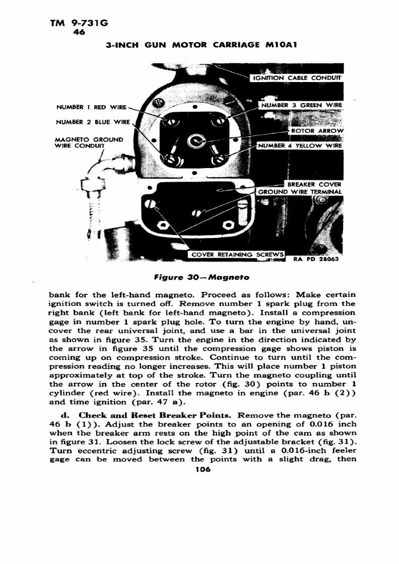
(1) REMOVAL (fig. 30). Remove four screw s securing breakerpoint inspection plate. Remove  plate.  Remove four screws securingmagneto circular inspection plate. Remove  plate. Remove  groundwire  terminal screw. Unscrew  knurled  nut securing  ground  wire  conduit to  the magneto housing  and remove ground wire and conduit.Remove four screws securing four ignition  (high tension)  cables  todistributor plate and  lift  ignition  cable  terminals out of recesses.Unscrew knurled nut securing ignition  cable conduit to magneto and

104

7/29/2019 TM9_731G_1943

http://slidepdf.com/reader/full/tm9731g1943 106/284

TM 9-731G46 

IGNITION SYSTEM

-LEFT HAND MAGNETO

8REEN

FIRING ORDER1R-2L-3R-1L-4R-3L-2R-4L

-YELLOW BLUE

-RIGHT HAND MAGNETORA PD 274 28

remove conduit and cables. Remove lock wire and upper  and lower

nuts  securing magneto to accessory gear cover and remove magneto.

CAUTION: Note the position of the rotor arrow (fig. 30) in the

center of the distributor plate before removing the magneto. The mag

neto must be replaced with the  arrow pointing to the same terminal

as when removed. If engine has been turned over with magneto re

moved, proceed as outlined in  subparagraph c below.

(2) INSTALLATION. To install the magnetos, reverse the sequence

of the  steps in the removal procedure, and also check the ignitiontiming as outlined in paragraph 47, and adjust the magnetos in the

housing slots as  outlined in paragraph 47 a (4). 

If timing

has been lost due to engine having been turned over while either

magneto was  removed, it will be necessary to get number 1 piston

of the right-hand bank of cylinders at the top of its compression

stroke, to set the right-hand magneto, or  number 1 piston of the left

105

7/29/2019 TM9_731G_1943

http://slidepdf.com/reader/full/tm9731g1943 107/284

TM 9-731G46

3-INCH GUN MOTOR CARRIAGE M10A1

NUMBER 1 RED WIRE

NUMBER 2 BLUE WIRE

MAGNETO GROUNDWIRE CONDUIT

BREAKER  COVER

GROUND WIRE TERMINAL

COVER RETAINING  SCREWSRA PD  28063

bank for the left-hand  magneto. Proceed as  follows: Make certain

ignition switch is turned off. Remove number 1 spark plug  from the

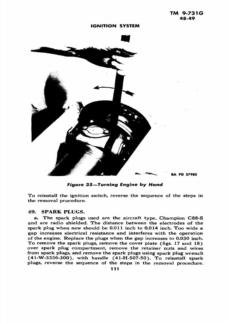
right bank (left bank  for left-hand magneto). Install a compressiongage in number 1 spark plug hole. To turn the engine by hand, un

cover the rear universal joint, and use a bar in the universal joint

as shown in figure 35. Turn the  engine in the direction indicated by

the arrow in figure 35 until the  compression gage shows piston is

coming up on compression stroke. Continue to turn until the com

pression reading no longer increases. This will place number 1 piston

approximately at top of the  stroke. Turn the magneto  coupling until

the arrow in  the center of the rotor (fig. 30) points to number 1cylinder (red wire). Install the  magneto in engine (par. 46 b (2))and time ignition (par. 47 a).

Remove the magneto (par.

46 b (1)). Adjust the breaker points to an opening of 0.016 inch

when the breaker arm rests on the high point of the cam as shown

in figure 31. Loosen the lock screw of the adjustable bracket (fig. 31).

Turn eccentric adjusting screw (fig. 31) until a 0.016-inch feeler

gage can be moved between the points with a slight  drag, then

106

7/29/2019 TM9_731G_1943

http://slidepdf.com/reader/full/tm9731g1943 108/284

TM 9-731G 46-47

IGNITION SYSTEM

ECCENTRIC ADJUSTING SCREW

ADJUSTABLE BRACKET LOCK

BREAKER

OF CA M

V»CAP SCREW HOLDING EMOVE TO LIFT OFF* BREAKER ARM SPRING BREAKER ARM

LOWER TIMING SLOT

RA PD 27494

Figure 31—Magneto with Breaker Point Cover Removed

tighten the lock screw to hold the adjustment. The contact points

must be free from oil or grease and be in alinement with each other,

so that the full surfaces of both contacts meet squarely. Pitted con

tact points should be replaced (par. 46 e). In emergencies, the

points sometimes can be cleaned with an extremely fine hone. Do

not use a file. When point replacement becomes necessary, always

replace both the breaker arm and the contact bracket.

(fig. 31). To remove the breaker

points, remove the cap screw which holds breaker arm spring, then

remove cotter pin and washer from breaker arm pin and lift out the

breaker arm. Remove the lock screw which holds adjustable bracket,

and lift bracket off of the eccentric adjusting screw. To reinstall the

breaker points, reverse the sequence of the steps in the removal

procedure and adjust breaker points (par. 46 d).

47.

(1) PRELIMINARY STEPS. Open the engine compartment doors.

Remove the four screws from the flywheel inspection plate (fig. 18)

on the top left side of the flywheel housing and remove the plate.

Make certain that the ignition switch is off; then turn engine by

hand (fig. 35) until the timing mark "SPARK SETTING R.H."

appears at the opening in the flywheel housing from which the plate

was removed (fig 32). Make a narrow chalk mark across the flywheel

7/29/2019 TM9_731G_1943

http://slidepdf.com/reader/full/tm9731g1943 109/284

TM 9-731G47

3-INCH GUN MOTOR CARRIAGE M10A1

RA PD 27278

Figure 32 —Flywheel Timing Marks

on the "SPARK SETTING" mark. Turn the engine  until the other

timing mark "SPARK SETTING L.H." (fig. 32) appears at the open

ing and make a chalk mark as outlined above. NOTE: On early

production engines having  the mark "SPARK  RETARDED" on the

flywheel instead of "SPARK SETTING", the timing is correct  when

the pointer in the flywheel housing is seven-eighths inch to the right

of the "SPARK RETARDED" mark when the spark occurs. There

fore, a chalk mark  should be placed across the flywheel seven-eighths

inch to the right of both of the "SPARK  RETARDED" marks.

(2)  CONNECTING THE TIMING LIGHT. To connect the timing light,

remove the nuts from the spark plug  covers and remove the covers.

Remove the spark plug wire from number 1 spark plug in  the right

bank to check  right-hand magneto. (Use number 1  spark plug in

left-hand bank to check left-hand magneto.) Procure a short pieceof high tension wire and attach connector and terminal. Insert this

wire in number 1  spark plug (fig. 34). Attach the high tension lead

(large wire) of the timing light to  the  terminal of number 1 spark

plug wire and also to the connector of the short piece  of wire just in

serted in the  spark  plug. Connect  one end of a 12-foot length  of

insulated  wire to the positive post  of the. forward battery; attach the

other end to the positive (red) low tension lead of the timing light.

Connect the other low tension lead to any convenient ground.

108

7/29/2019 TM9_731G_1943

http://slidepdf.com/reader/full/tm9731g1943 110/284

TM 9-731G 47

IGNITION SYSTEM

OPENING IN FLYWHEEL  HOUSING

SPARK SETTING MARK R. H.

POWER TIMING LIGHTRA PD 78038

Figure 33—Timing  Light

(3) USE OF NEON TUBE TYPE TIMING LIGHT. Start the engine

and allow it to warm up. Set the engine idling speed at 500 revolutions

per minute. Hold the timing  light over the opening in flywheel hous

ing so that it can flash on the timing marks (fig. 33). If  the "SPARK

SETTING" mark on the flywheel appears at the pointer, the timing

is correct. If the "SPARK SETTING"  appears to the left of thepointer, the timing  is  advanced; adjust magnetos (par. 47 a (4)). If

the mark appears to the right of the pointer, the timing is retarded

and should be adjusted (par. 47 a (4)). Repeat the above procedure 

for the second magneto.

(4) ADJUSTING  MAGNETOS TO CORRECT TIMING. Remove the lock

wire and loosen the upper and lower holding nuts on the magneto, and

move the magneto  in the housing slots toward the front (flywheel end

of the engine) to advance the timing, or toward the rear to retard

the timing. Recheck with timing  light (par. 47 a (3)). After correcttiming is obtained, tighten  magneto holding nuts and secure with

locking wire. Follow the same procedure in checking the timing and

adjusting the second magneto. Check the magneto governor advance

(par. 47 a (5)).  Replace wires on spark plug and spark  plug cover

plates.

NOTE: If the timing is advanced or  retarded more than 3 degrees

or approximately one-half inch on the flywheel rim,  it will be neces-

109

7/29/2019 TM9_731G_1943

http://slidepdf.com/reader/full/tm9731g1943 111/284

TM 9-731G47-48

3-INCH GUN MOTOR  CARRIAGE M10A1

.CONNECTOR. TERMINAL

TIMING LIGHT

HIGH  TENSION WIRE 

SPARK PLUG CA P

NO. 1 SPARK PLUG WIRE

RA PD 28064

Figure  34—Timing Light Connections 

sary to reset the timing  by adjusting the magneto drive gear. Notify

ordnance maintenance personnel.

(5) CHECKING MAGNETO GOVERNOR ADVANCE. Before attempting 

to check the magneto governor action, the initial timing must be estab lished  (par. 47 a  (1) through (4)). With the timing light still con

nected, increase  the speed of the engine, and observe the mark on  the

flywheel. The  governor  will start to advance when the engine speedreaches 600 revolutions per minute, and will be  fully  advanced when 

it reaches 1,400  revolutions per minute. The  timing mark should move

to  the left of the pointer as the speed of the engine increases until the

spark timing reaches maximum advance, at  which time the flywheel

mark will be approximately 2 s/s inches to  the left of  the pointer. If

the timing mark does not change  its position  in relation  to the pointerwhen the  engine speed is increased, the magneto governor is faulty

and should be replaced. Notify ordnance maintenance  personnel.

a. The operation of the ignition switch  is described in paragraph

5 a  (6). To replace the ignition switch, remove  the instrument panel(par. 80 b). Remove the four bolts which hold the switch to the in

strument panel and pull switch  out through the back of the panel.Disconnect the  right and left ignition wire. NOTE: As these wiresare the same color, it will be necessary to tag each wire when removed.

110

7/29/2019 TM9_731G_1943

http://slidepdf.com/reader/full/tm9731g1943 112/284

TM  9-731G

48-49 

IGNITION SYSTEM

RA PD 2798 5

Figure  by Hand

To reinstall the ignition switch, reverse the sequence of the steps in

the removal procedure.

a. The spark  plugs used are the aircraft type, Champion  C88-S

and are radio  shielded. The distance between the electrodes of the 

spark plug when new should be 0.011 inch to 0.014 inch. Too  wide a

gap increases electrical resistance  and interferes with the operation

of the engine. Replace the plugs when the gap increases to 0.030 inch.

To remove the spark plugs, remove the cover plate (figs. 17 and 18)

over spark plug compartment, remove the retainer nuts  and wires

from spark plugs, and remove the spark plugs using spark plug wrench(41-W-3336-300), with handle (41-H-507-50).  To reinstall sparkplugs, reverse the sequence of the steps  in the removal procedure.

Ill

7/29/2019 TM9_731G_1943

http://slidepdf.com/reader/full/tm9731g1943 113/284

TM 9-731G 50

3-INCH GUN MOTOR CARRIAGE M10A1

a. General. The  wires leading from  the  magneto to the spark

plugs may be identified for both right- and left-hand magneto by colorsmarked on the wires as follows: No. 1 red, No. 2 blue, No. 3 green,

and No. 4 yellow. Spark plug wires, having cracked or damaged in

sulation, must  be replaced  as such wire  may cause misfiring of the

spark plug to which they are attached. If the flexible conduit becomes

damaged  or frayed out, it also must  be replaced to avoid chafing of

the spark plug wires.

(1) REMOVAL. To remove one or more spark  plug wires, remove

the spark plug cover plates (figs. 17 and 18), and remove the circular

plate covering the spark plug wire terminals on the magneto  (fig. 30).

Remove the retainer nut from the spark plugs of  the  wires to be

changed, and disconnect the terminals at the other end of the wires

from the magneto. Attach a strong cord to the terminal at the magneto

end of the wire and pull the wire out of the conduit. The cord  is to be

used  later  to pull a new wire through the conduit.

(2) INSTALLATION. Attach  the cord described in preceding para

graph,  and pull a new wire through the  conduit. Attach spark plug 

retainer nut and fitting  to  end of  the wire, and attach the  wire to the

spark plug. Attach the other end  of the wire to the proper terminal

on the magneto (fig. 30). 

c. Replacement of Flexible Conduit. To remove flexible conduit,

unscrew the knurled nut at each end of the flexible conduit. Remove

the spark plug wires from the magneto and slip conduit from  the wire.

To reinstall  flexible conduit, reverse sequence  of the steps in the re

moval procedure. Use new gaskets at each end of the flexible conduit.

Attach spark plug wires to the magneto in their proper order (fig. 30).

112

7/29/2019 TM9_731G_1943

http://slidepdf.com/reader/full/tm9731g1943 114/284

TM 9-731G51-52

Section XIII 

FUEL SYSTEM

Paragraph 

Fuel system ........................................ 51Carburetors .....................................  52Degassers ..........................................  53Carburetor adapters .................................. 54

Air  cleaners ....................................... 55  Throttle  controls .................................  56

Priming pump  ...................................... 57

Fuel pump .....................................Fuel filter ..........................................

58

59Fuel tanks ......................................  60

The fuel  system consists of  two carburetors

equipped with degassers, a fuel pump, four fuel  tanks with  fuel supply 

lines, a  fuel filter, and a  priming pump with supply  lines to the intakemanifolds. The total  capacity of the fuel tanks  is 192  gallons.

Trouble shooting for the fuel system iscovered in  paragraph 36 e,  f, i, j, in the engine section of this book. 

52. CARBURETORS (fig.  37).

Two Stromberg Model NA-Y5G carburetors areused, mounted on carburetor adapters  (figs. 19 and 20)  connecting 

the two intake manifolds at  each end. The carburetors are the dual(double-barrel) down-draft type. Each carburetor has two floats con

nected by one lever and operating on  one needle valve. A separate

main  metering and idling system is provided for each barrel. Each barrel is equipped with  a  degasser (par.  53). An accelerating pump,

which operates with the throttle,  provides an extra quantity of fuel

for rapid  acceleration.  The throttle linkage is arranged so that  the

forward carburetor  remains closed until the rear carburetor is ap

proximately half open (par. 56).

Two idle fuel adjustment screws areprovided on each carburetor, one fo r each barrel. The adjusting screws

are shown in figure 37. The  idle fuel adjustments on  these carburetors

are  extremely uniform  and can be adjusted when either cold or hot.Make the idle fuel adjustments with engine stopped. Turn each idle

fuel adjusting screw (fig. 37) in (clockwise)  until it seats lightly;

then turn out one-fourth turn from  the closed position. A  stub (short)screwdriver will be  required for making this  adjustment on  the forward carburetor.

Start the engine  and  run until it

reaches normal operating  temperature. Back off the idle  speed ad-

113

7/29/2019 TM9_731G_1943

http://slidepdf.com/reader/full/tm9731g1943 115/284

TM 9-731G

52

3-INCH GUN MOTOR CARRIAGE M10A1

tz

1si

Qa.

<

V

u.I

<O

O)

7/29/2019 TM9_731G_1943

http://slidepdf.com/reader/full/tm9731g1943 116/284

TM 9-731G 52

FUEL SYSTEM

FUEL LEVEL CHECKING PLUG

IDLE FUEL ADJUSTMENTS

• IDLE SPEED ADJUSTMENT 

RA  PD 27408

Figure  37—Carburetor

justment (fig. 37) at each carburetor until the  engine idle speed is

below 500 revolutions per minute. Set the idle speed  adjustment at

one of the carburetors until the engine idle speed  is 500 revolutions

per minute. Set the idle speed adjustment at the other carburetor until

the  engine speed just starts to increase; then back off  the adjustmentslightly.

Each carburetor is  provided with fuel level

checking  plugs (fig. 37),  one at the front of the carburetor and one

at the rear. To check the fuel level, remove the lock wire and the

plug from  the inspection hole  in the front side  of the  rear carburetor, 

or the  rear side of the  forward carburetor. Start the engine and run

at idling speed. The fuel should be visible at the bottom of the threads

115

7/29/2019 TM9_731G_1943

http://slidepdf.com/reader/full/tm9731g1943 117/284

7/29/2019 TM9_731G_1943

http://slidepdf.com/reader/full/tm9731g1943 118/284

TM 9-731G

54-55

FUEL SYSTEM

TOCARBURETOR

AIR INTAKE

AIR INTAKE^

FILTERELEMENT

RA PD 27277

f igure 38—Air Cleaner—Section

Remove the carburetor (par. 52 e). Disconnect the clevis at the end

of governor throttle rod. When removing the rear adapter, disconnect

the ball joint at the governor arm. Remove the six nuts which hold

the adapter to the manifold.  Remove adapter. To install the car

buretor adapter, reverse the sequence of the steps in this procedure.

(fig. 38).

Two air cleaners of the oil bath type are located

one at the right side, and one at the left side of the engine compart

ment mounted  on the bulkhead.

Remove the three wing nuts from the bottom

plate of the cleaner, and remove the baffle  and cup assembly. Remove

the filter element by pulling the  clip down. Wash the filter element

with dry-cleaning solvent. Dry and blow out with compressed air inreverse direction to normal air travel. Clean and refill the cup to

proper level with oil specified (section VI). Care should be taken

not to fill the cup above the oil level mark. Place  the cup assembly on

cleaner and fasten with the three wing nuts. Check carburetor air

manifold tube connections for leaks.

Disconnect the air tube connections at car

buretor air intake manifold and air cleaners. Remove the tubes. Re-

117

7/29/2019 TM9_731G_1943

http://slidepdf.com/reader/full/tm9731g1943 119/284

TM  9-731G 55

3-INCH GUN MOTOR CARRIAGE M10A1

V a)

o

•e

I o.

O) 

8118

7/29/2019 TM9_731G_1943

http://slidepdf.com/reader/full/tm9731g1943 120/284

7/29/2019 TM9_731G_1943

http://slidepdf.com/reader/full/tm9731g1943 121/284

TM 9-731G 56-59

3-INCH GUN MOTOR CARRIAGE  M10A1 

(2) REPLACEMENT.  Remove the screws from the driver's compart

ment subfloor and remove the  floor. Remove the lock wire and bolt

from the bracket at the base of the throttle pedal, also remove the clevis pin from the rod connecting the pedal to the cross shaft at the

rear of the driver's seat. Remove the pedal. To install the foot throttle

pedal, reverse the sequence of the steps in the removal procedure.

The operation of the governor which con 

trols and limits the  engine speed through additional throttles in the

carburetor adapters is described in paragraph 39 a. Adjustment of

governor throttle control rod is outlined in paragraph 39 a.

The operation of the priming pump located on

the front bow in driver's compartment (fig. 7) is described  in para

graph 5  b (4).

Disconnect the inlet and outlet gasoline lines

at  the priming pump. Remove the  two  cap screws from each side of

the priming pump bracket and remove the priming pump. To reinstall,

reverse  the sequence of the steps in the removal procedure.

The fuel pump  is of the  conventional diaphragm 

type (AC) and  is mounted on the left-hand cylinder head (fig. 18).

The pump is driven by the left intake camshaft. The pump maintains

from 4 l/2 to 6 pounds fuel pressure in the carburetors.

At each inspection, the pump should be

checked for leaks at connections, and for tightness of screws on top

of pump. To test the fuel pump, disconnect fuel line at either outlet

connection  at the pump, and attach a fuel pressure gage. Using the

starter, crank  the engine. The fuel pressure should be between 4 l/2

and 6 pounds. Low pressures will starve the carburetor under full

load. High pressures will cause a high fuel level in the carburetor float

bowl.

Close the fuel shut-off valves (fig. 9). Discon

nect the inlet and outlet fuel line connections at the pump. Remove

the two nuts which secure pump to cylinder head  and remove the

fuel pump. To  install the fuel pump, reverse the sequence of thesteps in this removal procedure. NOTE: Approximately 20 seconds

are required  for a dry fuel pump to supply fuel while engine is being

cranked with the starter.

(fig. 40). The filter assembly consists of a stack-

type disk element and a metal filter bowl located on left side of the

engine compartment. Inlet and outlet passages are marked "IN" and

120 

7/29/2019 TM9_731G_1943

http://slidepdf.com/reader/full/tm9731g1943 122/284

TM 9-731G 59

FUEL SYSTEM

GASKET

GASKET

FILTER ELEMENT

SPRING

BOWL

DRAIN PLUG

RA PD 27*89

Figure 40-Fuel Filter

"OUT". The filter element consists of a large number of filter disks

(0.020 in. thick) stacked and squeezed together.

Close the fuel shut-off valves and remove the drain

plug at the bottom of the filter bowl to remove accumulated dirt and

water.

(fig. 40). Remove the center stud at

the top of the filter. Remove and clean the bowl and wash the filter

element in dry-cleaning solvent. Care must be taken to prevent dam

age to the disks. Do not scrape or scrub the disks. Do not attempt

to disassemble the filter element; replace element if it cannot be

cleaned satisfactorily. Before replacing filter bowl, inspect and replace the gasket if necessary.

To remove the filter assem

bly, close the fuel shut-off valves (fig. 9). Disconnect the filter outlet

pipe at the fuel pump and disconnect fuel pipe from the filter. Dis-

121

7/29/2019 TM9_731G_1943

http://slidepdf.com/reader/full/tm9731g1943 123/284

TM 9-731G 59-60

3-INCH GUN  MOTOR CARRIAGE M10A1

Figure 4 J—Fuel Tank Drain  Plug

connect the inlet pipe connection at the filter. Remove the two cap

screws which hold the filter to the fire  wall. Remove the filter. To

reinstall, reverse the sequence  of steps in the  removal procedure.

60.  FUEL TANKS.

a.  Location and Capacity. Four horizontal fuel tanks are pro

vided. Two are located in  the engine compartment right sponson  and

two in the left sponson. The  capacity of  the  right and  left rear tanks

is 39 Va gallons each. The capacity of the right front tank is 58 gallons.

The capacity of  the left front  tank is 55  gallons.

The drain plug  for the right front tank

is located on the bottom of the right sponson just above the rear bogie

track support wheel.  The drain plug for the left front  tank is located

in a similar position on the bottom of the left sponson. The drain

plug for  the right rear tank is located on the bottom  of the  right

sponson above the track idler wheel. The  drain plug for the left

rear tank is located in a  similar position on the bottom of the left sponson. To remove any  of the four drain  plugs, proceed as follows:

Remove two screws from the round plate on the bottom of the sponson

and  loosen the  third  screw.  Swing the round plate out of the way

(fig. 41). Remove the drain plug.

(1) REMOVAL. Drain the tank (par. 60 b). Disconnect the fire

extinguisher line connections  at nozzles,  and remove the  lines which

122

7/29/2019 TM9_731G_1943

http://slidepdf.com/reader/full/tm9731g1943 124/284

TM 9-731G60

FUEL SYSTEM 

are in front of the fire wall. Disconnect the fuel line and remove fuel

line elbow  from the tank. Disconnect radiator vent pipe at the radi

ator and at the expansion tank, remove the holding clips, and removethe pipe. Remove the cap screws and nuts which hold the fire wall to

the sponson and remove the fire wall. Remove the bolt from each

hold-down strap. Remove the filler cap. Move the tank  part way

out and disconnect fuel level gage wire from tank  float. Remove

the tank.

(2) INSTALLATION. Reverse the  sequence of the steps in the re

moval procedure.

Follow  the sequence ofthe steps for the removal of the right front tank (par. 60 c) and in

addition remove the fuel  filter (par. 59 d) and the expansion tank

(par, 69 b). To reinstall the left front tank, reverse  the sequence of

the steps of this removal procedure.

(1) REMOVAL. Drain the tank (par. 60 b). Remove the front tank

(par. 60 c). Disconnect the fuel line at the tank, and remove the

fuel line elbow from the tank. Remove  the fan and shroud assembly

(par. 66  d). Remove upper radiator baffle (par. 64 b). Remove the

cap screws and nuts which hold  the fire wall to the  sponson and re

move the fire wall. Remove the cap screws which hold the rear in

spection plate to the  sponson and remove the plate. Remove bolt

from each hold-down strap. Remove the filler cap. Move the tank

forward, and disconnect the fuel level gage wire from the tank float.

Remove the tank.

(2) INSTALLATION. Reverse the sequence of the steps in the re

moval procedure.

A  shut-off valve  for each tank

is located in  the left side of the engine compartment with controls in

the fighting compartment on the forward side of the bulkhead (fig. 9).

7/29/2019 TM9_731G_1943

http://slidepdf.com/reader/full/tm9731g1943 125/284

TM 9-731G61-42

3-INCH GUN MOTOR CARRIAGE M10A1

Section XIV

COOLING  SYSTEM

Paragraph

Cooling  system ...................................... 61Antifreeze ..........................................  62Corrosion inhibiter  ................................... 63 Radiator ...........................................  64

Water pump  .........................................

Fans ........................'......................

65

66

Accessory drives.....................................

67

Thermostat ........................................ 68

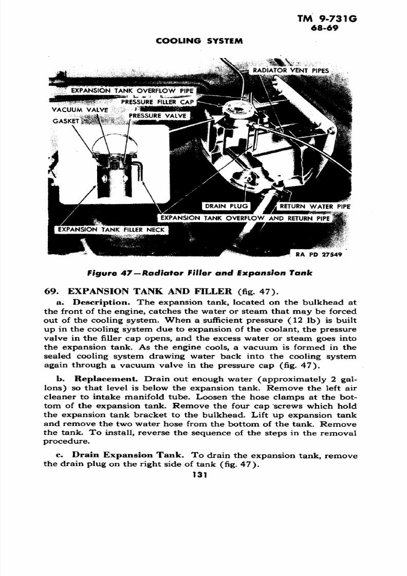
Expansion tank and filler..............................  69

(fig. 42). The engine  is cooled by circu

lation of water through the water jackets which extend the  full lengthof the cylinder bores. The water is circulated through the engine block

and radiator by a centrifugal pump (par. 65).

The entire  cooling  system is sealed by

means of a pressure filler cap which remains closed until a pressure of 

12 pounds is  reached. This  results in raising the  boiling point of thewater, thus reducing loss of water or antifreeze. An expansion tankpermits steam  or antifreeze vapors to condense and return to the

cooling system further reducing the  loss of water or antifreeze.

The capacity of the entire cooling system  is 17 gal

lons.

Always use clear water, preferably rain or soft

water if possible. Do not  put cold water into the system  when the

engine is hot. The radiator and cooling system should be drained,flushed, and  refilled with clean water and corrosion inhibiter added

(par. 63)  at each 1,000 mile inspection (par. 33 a  (5)). A drain plug

is  provided at the bottom of the water pump (fig. 21). The expansiontank is provided with a drain plug  (fig. 47). A  drain plug at the rear

of each bank of cylinders located approximately 6 inches ahead of the

engine rear mounts (figs. 17 and  18), is provided for draining the waterfrom the cylinder block. NOTE: On earlier production engines thecylinder block  drain plugs are located at the engine rear mounts

(fig. 43).

a. High  boiling point permanent antifreeze  solutions or alcohols are satisfactory as antifreeze solutions. However, a corrosion inhibitermust be  used, preferably as part of the antifreeze.

124

7/29/2019 TM9_731G_1943

http://slidepdf.com/reader/full/tm9731g1943 126/284

TM  9-731G

62-64 

COOLING SYSTEM

-RADIATOR (UPPER) WATER CONNECTION RADIATOR VENT

PIPEs

-TEMPERATURE   GAGE ENGINE UNIT

FAN SHROUDEXPANSION TANK

FAN

FAN  BELTS

PRESSURE  FILLER CAP

EXPANSION TANK

OVERFLOW PIPE

BOIL GAGE- WATER MANIFOLDS ENGINE UNIT

WATER  PUMP CONNECTION

TO CYLINDER BLOCKWATER  LEVEL PET COCK

RADIATOR  (LOWER)

WATER CONNECTION

RADIATOR VENT PIPE 

FAN

FAN SHROUD

RA PD 27550RADIATOR 

Figure 42 — Cooling System

a. To control rusting of the iron in the cooling system and the corrosion of the aluminum  cylinder block and cylinder heads, a soluble 

oil corrosion inhibitor must be used. It is important when the cooling

system is  refilled with fresh water after draining, especially when 

antifreeze is not being used, that 14  ounces of  this inhibiter  be added 

to  the water.

The radiator is of the tube and fin cross-flow 

125

7/29/2019 TM9_731G_1943

http://slidepdf.com/reader/full/tm9731g1943 127/284

TM 9-731G64

3-INCH GUN MOTOR CARRIAGE M10A1

>- fi

RA PD 27424

type, using flat horizontal tubes. The hot water flows through the tubes

to which are attached thin vertical copper fins. Air forced between

these fins by the fans carries the heat away, thus cooling the water.

(1) REMOVAL OF RADIATOR.

(a) Preliminary Work. Open the engine compartment doors. Re

move the three cap screws which hold the rear door of the engine

compartment closed. Raise the radiator air baffle and allow it to rest

on top of the engine compartment rear door after the door is all the

way open. Remove the cap screws which secure the engine compart

ment rear cover plate to the hull and lift the cover from the hull with

a chain fall or hoist (fig. 25). Remove the four bolts which secure theradiator hold-down plate to the fan shrouds and remove the plate.

Remove the plug at the bottom of the water pump (fig. 21) and drain

the cooling system. Loosen hose clamps, and remove the radiator

upper hose and radiator to water pump hose.

(b) Remove Radiator Upper and Lower Water Connections. Re

move the four cap screws from the radiator upper and lower waterconnections, and remove the connections.

126

7/29/2019 TM9_731G_1943

http://slidepdf.com/reader/full/tm9731g1943 128/284

TM 9-731G 

64-65

COOLING SYSTEM

RADIATOR LIFTING HOOK

RADIATOR

RA PD  27414

Figure 44—Radiator Removal

(c) Remove Upper and Lower Radiator Baffles and  DisconnectVent Pipes. Remove one bolt on each end which holds the lower air

baffle and remove baffle. CAUTION: The air baffle can be rested on

top of the engine compartment rear  door to take some of the weight 

off the bolts; however, to remove the baffle requires two  men, one ateach end to hold baffle up as bolts are removed so that it can be lowered

gradually. Remove one bolt at each side of the upper radiator air

baffle located at  the top rear of the radiator, and remove through the

opening below baffle.  Disconnect both ends of  the short length of each

vent pipe at the top of the radiator and remove the pipes.(d) Remove Radiator. Connect radiator lifting hook and carefully

pull out radiator (fig . 44), using a chain fall  or hoist.

(2)  INSTALLATION OF RADIATOR. To  install the  radiator, reverse

the sequence of the steps in the removal procedure.

(fig. 21). The water pump is a centrifugal type

driven by a splined shaft from the  rear of the crankshaft.

127

7/29/2019 TM9_731G_1943

http://slidepdf.com/reader/full/tm9731g1943 129/284

TM 9-731G 65-66

3-INCH GUN MOTOR CA RRIAGE M10A1

The water pump is lubricated from the engine

and a permanent water seal is used; therefore, no attention is required.

(1) REMOVAL. Open the rear door of the engine compartment

(par. 64 b (1) (a)).  Remove the plug at the bottom of the water

pump (fig. 21) and drain the cooling system. Loosen the hose clamps,

and remove the two hose running from the radiator to the water pump.

Remove the four nuts which hold  the water pump to the crankcase,

two at center connection  and two at water connection at the left, and

remove the pump.

To install the water pump, re

verse the  sequence of the steps in   the removal procedure, using new 

gaskets and water hose connections if necessary.

66. FANS.

Two 2 6-inch diameter six-blade blower or pusher-

type fans are used. They are mounted in the front of the radiator. The

fans draw air in through the openings in the engine compartment doors 

and force the air out through the radiator and air baffles back of the 

radiator. Each  fan is  driven by two matched V-belts (fig. 45) from

pulleys on the accessory drive housings (mounted on the sides of the hull toward the rear of the engine compartment).

or adjustment of the fan belts is made by moving the accessory drive

housing  up or down in slots provided after loosening the four nutswhich secure the housing to the hull  sides. The belts are correctly ad

justed when approximately  1-inch movement can be obtained with

the fingers at a point midway between the  fan and  accessory drive 

pulleys  (fig. 45).  NOTE: When replacement of belts is made, always

replace both belts running on the same pulleys.

The fan bearings are packed  when

assembled and should require no further lubrication between overhaul

periods.

(fig. 22). Toremove fans and shrouds, open the engine compartment doors and re

move the engine compartment  rear cover plate (par. 64 b (1) (a)).

NOTE: It is not necessary  to  remove the  engine  compartment doors.

Loosen and  remove the fan belts  (par. 66 b). Remove the two  boltsand  four cap screws from each  fan shroud and remove the assemblies.

To  reinstall, reverse the sequence of the steps in the removal pro

cedure.

(1) REMOVAL.  Remove fan  and shroud assembly  (par.  66d).  Re

move the six  cap screws from the  fan hub and remove the pulley andfan blades. Bend up the  ear of the lock washer from  the slot in the

128

7/29/2019 TM9_731G_1943

http://slidepdf.com/reader/full/tm9731g1943 130/284

TM 9-731G

66-67

COOLING SYSTEM

RA  PD 27429 

Figure  45—Fan Belt Adjustment

round nut at the front of fan shaft and remove the nut with  a spanner 

wrench. Remove shaft and hub from  the shroud. Remove the roundnut at rear of shaft in the same manner as outlined  for removing front

nut; then tap out shaft using a soft hammer (lead, copper, or rawhide).

Tap the front bearing from  the hub with a brass drift and remove the

two spacers. Remove the lock ring and tap out the rear bearing with

a brass drift.

(2)  INSTALLATION. To install the  fan bearings, reverse the

sequence of the steps in the  removal procedure. Make certain that

both bearings are packed with lubricant before assembling.

The accessory drives are located  on the right

and left walls  of the engine compartment to the rear of the  engine.

These accessory drives contain bevel gears running in engine oil which

transmit the power from the engine accessory shafts to drive the gen

erators and fans. The accessory drives are provided with bayonet type

oil level gages, which are a part of the filler plugs.

129

7/29/2019 TM9_731G_1943

http://slidepdf.com/reader/full/tm9731g1943 131/284

TM 9-731G

67-68

3-INCH GUN MOTOR CA RRIAGE M10A1

BOIL GAUGE ENGINE UNIT

TEMPERATURE GA UGE ENGINE UNIT

RADIATOR INLET HOUSING 

THERMOSTAT

WATER LEVEL PET COCKGASKET  GASKET

RA PD 77869

Figure  46—Thermostat

(1) REMOVAL. Remove the accessory drive shaft (par. 37a(12)).

Remove th,e generator (par. 72 c). Loosen the four nuts securing the 

accessory drive housing to the hull, and lift the assembly so that the

fan belts can be removed from the pulleys. Take off the nuts and re

move the accessory drive assembly from the hull. NOTE: The above

procedure applies to either the right or left accessory drive.

(2) INSTALLATION. Reverse  the sequence of the steps in the re

moval procedure.

(fig. 46). The thermostat located in the inlet

opening of the radiator is of the bypass bellows type and is nonadjust-

able. This thermostat prevents the circulation of water in the radiator

until the engine reaches normal operating temperature. The thermo

stat starts to open at  140 F. 

Open the engine compartment doors.  Remove

drain plug at bottom  of water pump (fig. 21) and drain out enough

water (approximately 2 gallons) so that the level is below the thermo

stat. Remove the four cap screws from radiator upper water connec

tion. Loosen hose clamps  from both radiator upper hose at the engine

and at the thermostat housing. Remove the hose. Remove the water

connection and the thermostat from  the radiator (fig. 46). To install,

reverse the sequence of the steps in the removal procedure, installingnew gaskets  if required.

130

7/29/2019 TM9_731G_1943

http://slidepdf.com/reader/full/tm9731g1943 132/284

TM 9-731G 68-69

COOLING  SYSTEM 

RADIATOR VENT PIPESS'ski.

EXPANSION TANK OVERFLOW  PIPE

PRESSURE FILLER CAP

VACUUM VALVE * 5s

_ ,_ _ .....„.' PRESSURE VALVEGASKET

DRAIN PLUG M M i RETURN WATER PIPE

••••PM^

EXPANSION TANK OVERFLOW AND RETURN PIPE

•EXPANSION TANK  FILLER NECK

RA PD  27549

Figure 47—Radiator Filler and Expansion Tank 

The expansion tank, located  on the  bulkhead at the front of the engine, catches the water or steam  that may be forced

out of the cooling system. When a sufficient pressure (12  Ib) is builtup  in the cooling system due to expansion of the coolant, the pressure

valve in the  filler cap opens, and the excess water or steam goes into

the expansion tank. As  the engine  cools, a vacuum is formed in thesealed cooling  system drawing water back  into the cooling system

again  through a vacuum valve in the pressure cap (fig. 47).

Drain out enough water (approximately 2 gal 

lons) so that level is below the expansion  tank. Remove the left air 

cleaner to intake manifold tube. Loosen the  hose clamps at the  bottom  of the expansion tank. Remove the four cap screws which hold

the expansion tank bracket to  the bulkhead. Lift up expansion tank

and remove the two water hose from the bottom of the tank. Remove

the tank. To install, reverse  the sequence of the steps in the  removalprocedure.

To drain the expansion tank, remove

the drain plug on the right side of tank (fig. 47).

131

7/29/2019 TM9_731G_1943

http://slidepdf.com/reader/full/tm9731g1943 133/284

TM  9-7310 70

3-DNCH GUN MOTOR  CARRIAGE M10A1 

Section XV ELECTRICAL SYSTEM AND EQUIPMENT

Paragraph

General description .................................. 70Generating system  .................................. 71Generators .......................................... 72Generator circuit breaker.............................. 73 Generator  regulator .................................. 74Generator filter ..................................... 75Battery

............................................76Starting system  .....................................  77

Starter  ............................................  78Starter solenoid ..................................... 79Instrument panel  ....................................  80Circuit  breakers ..................................... 81Fuel  cut-off switch ..................................  82Utility outlet sockets .................................. 83Ammeter .......................................... 84Ignition  switch

......................................85Voltmeter .........................................  86

Blackout driving  light switch........................... 87Starter button  ....................................... 88Light  switch  ........................................ 89Fire detector signal................................... 90Instrument panel lights. .............................. 91Transmission oil temperature gage......................  92Oil level gage....................................... 93Low oil pressure signal................................  94Engine  boil signal.................................... 95Engine temperature gage............................. 96Fuel level gage...................................... 97Fuel level gage  selector switch. ........................ 98Panel light rheostat switch............................. 99Battery master switch. ............................... 100Radio  master switch. ................................. 101Headlights ........................ ................  102 Taillights

.........................................103Stop  light switch .....................................  104

Compartment light ..................................  105 Inspection light  ..................................... 106Siren ..............................................  107Conduits and wires................................... 108Trouble  shooting  .................................... 109

132

7/29/2019 TM9_731G_1943

http://slidepdf.com/reader/full/tm9731g1943 134/284

TM 9-731G 70

ELECTRICAL  SYSTEM AND EQUIPMENT

HEADLAMPS 

FRONT TE RMINAL BOX

INSTRUMENT PANEL

TRANSMISSION OILTEMPERATURE GAGE

BATTERY MASTER SWITCH

RADIO MASTER SWITCH

STARTING  MOTOR

SOLENOID RADIOTERMINALAMMETER SHUNT

BO X

DOME LIGHT

FIRE DETECTORS BATTERIES

CIRCUIT BREAKERGROUND CABLE

R.H. GENERATOR REGULATOR

L.H. FUEL L.H. GENERATOR REGULATOR

TANK TE RMINAL BOX COVERS 

GAGES FIRE DETECTORS

STARTING MOTOR

R.H. FUEL TANK GAGES 

CIRCUIT  BREAKER

R.H. GENERATOR 

CARBURETOR DEGASSERS

OIL LEVEL GAGE ENGINE UNIT

UTILITY SOCKETTEMPERATURE GAGE

REAR TERMINAL BOX OIL  PRESSURE GAGE ENGINE UNIT

TAIL LAMP RA   PD 27548

Figure 48—Electrical System

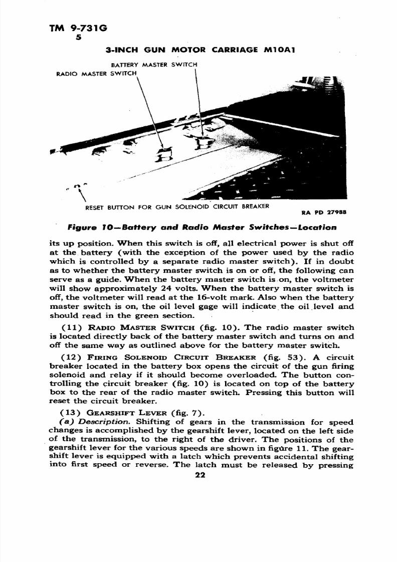
a. The  Gun Motor Carriage M10A1 uses a  24-volt electrical sys

tem. All units of  the electrical system are designed for 24-volt  operation with the exception of the blackout driving lamps.  The  blackout

driving  lamp circuit includes  a resistance (fig. 55)  that permits theuse of  6-volt bulbs. Figure 48 shows the location of each of the unitsof  the electrical system with regard  to other units. The electrical sys 

tem consists  of: the generating system  (par. 71), the  starting system

(par.  77), the electrical instruments (pars. 80 through  99), and the

light and siren circuits (pars. 102 through 107). General discussions

that apply  to the entire  electrical system are given in paragraphs 70,

133

7/29/2019 TM9_731G_1943

http://slidepdf.com/reader/full/tm9731g1943 135/284

TM  9-731G

70 

3-INCH  GUN MOTOR  CARRIAGE  M10A1 

•i

en 

o>

I I

134

7/29/2019 TM9_731G_1943

http://slidepdf.com/reader/full/tm9731g1943 136/284

7/29/2019 TM9_731G_1943

http://slidepdf.com/reader/full/tm9731g1943 137/284

TM 9-731G 71

3-INCH GUN MOTOR CA RRIAGE M10A1

VOLTMETER

AMMETER

INSTRUMENT PANEL

BATTERY MASTER SWITCH

RADIO MASTER SWITCH

AMMETER SHUNT

BATTERY GROUND CABLE

R. H. GENERATOR REGULATOR

L. H. GENERATOR REGULATOR 

GENERATOR CIRCUIT BREAKER

L. H. GENERATOR

GENERATOR CIRCUIT BREAKER

R. H. GENERATOR

RA PD 27551

Figure 50—Generating System

136

7/29/2019 TM9_731G_1943

http://slidepdf.com/reader/full/tm9731g1943 138/284

TM 9-731G 71

ELECTRICAL SYSTEM AND EQUIPMENT

(3) BATTERY CHARGES  FULLY  BUT  RUNS DOWN QUICKLY.

Poss ible Cause

Battery is worn out or defective.Short circuit in system (subpar. 

c (2)  above). 

Cut-out points fail to open.

(4) GENERATOR BURNS OUT.

Faulty generator regulator.

Armature and field wires trans

posed at either the generator

or the regulator.

Po ss ib le Rem ed y

Replace (par.  76 Locate and correct (par. 109 I»

(2)).

Replace generator regulator

(par. 74 c).

Replace generator (par. 72 c)

and  generator regulator (par.

74 c).Replace the generator (par. 72c) and the generator regulator

(par. 74 c) and connect wires

correctly  (fig. 49).

(5) GENERATOR FAILS  TO GENERATE OR GENERATES  INSUFFI CIENTLY.Generator burned out.

Generator commutator

(par. 72 b (2)).

dirty

Generator commutator worn (par.  72 b (2)).

Generator brushes 

72 b (2)).

worn  (par.

Generator brushes sticking (par. 

72 b (2)). 

Excessive resistance in generator

ground circuit (subpar. b 

above).

Excessive resistance in generator

armature  brush to battery cir

cuit (subpar. c above).

Resistance in cut-out points

(subpar. c above).

Voltage regulator incorrect (par.74  a (1)).

Current limitation incorrect

(par. 74 a (2)).

Cut-out closing  voltage too high.

Replace generator (par. 72 c)

and  generator regulator  (par.

74 c) making sure armatureand field wires are not trans 

posed.

Clean commutator with sand

paper.

Replace generator (par. 72 c).

Replace brushes.

Free brushes.

Clean and tighten all contacts as

outlined  in subparagraph b 

above.

Remove excessive  resistance 

(see subpar.  c  above  for

points of possible resistance).

Replace generator regulator

(par.  74 c).

Replace generator regulator 

(par. 74 c).

Replace generator regulator 

(par. 74  c).

Replace  generator regulator 

(par. 74 c).

7/29/2019 TM9_731G_1943

http://slidepdf.com/reader/full/tm9731g1943 139/284

TM 9-731G 71-73

3-INCH GUH MOTOR CARRIAGE M10A1

Probable Causa Probable Remedy

Cut-out points fail to close due Establish a good ground from the

to the generator regulator regulator housing to the hullnot being grounded. to complete cut-out shunt coil

circuit.

Cut-out points fail to close due Replace generator regulator

to defective shunt coil. (par- 74 c).

(6) AMMETER READS ABOVE NORMAL (par. 5 a (1) (d)).Ammeter defective. Replace ammeter (par. 84 a).Generator regulator faulty. Replace generator regulator

(par. 74 c).

(7) VOLTMETER READS ABOVE NORMAL (par. 5 a (1) (/)).Voltmeter defective. Replace voltmeter (par. 86).

Generator regulator not limiting Replace the generator regulator

the voltage. (par. 74 c).

72. GENERATORS.

Two special Ford tank generators model GAAare used. The rating of each generator is 30 volts 50 amperes. The

capacity of each is 1,500 watts. Current control is obtained by generator regulators (par. 74) mounted on the floor of the fighting compartment (fig. 51). The generators are mounted on the accessory

drive housing on each side, of the engine compartment and driven by

the accessory drive shafts (fig. 22).

(1) LUBRICATION. Generators are properly lubricated at overhaul

periods and should not require additional lubricant between overhaul

periods.

(2) INSPECTION. Remove generator cover band and inspect commutator and brushes at regular intervals. Check the brushes for stick

ing and wear; check commutator for wear. If the commutator is out

of round, badly worn, or scored, replace the generator. In an emer

gency, if the commutator is dirty it may be cleaned with PAPER,flint, class B, No. 00. Never use emery cloth to clean a commutator.

Open engine compartment doors.Turn off battery master switch. Disconnect wires from armature and

field terminals. Disconnect flexible conduit. Remove the four nuts

which hold the generator to accessory drive housing and remove the

generator. To install the generator; make certain that there is no paint

on generator or accessory drive housing flange. Reverse the sequence

of the steps in the removal procedure.

73.

The generator circuit breaker located in the gen

erator terminal box on the top of each generator is thermostatically

138

7/29/2019 TM9_731G_1943

http://slidepdf.com/reader/full/tm9731g1943 140/284

TM 9-731G 73-74

ELECTRICAL SYSTEM AND  EQUIPMENT

R1GHT HAND GENERATOR REGULATOR

SPRING LOADED DRAIN VALVE 

FIRE EXTINGUISHER! !' " !<

TERMINAL BOX COVER

WIRE CONDUITS

TERMINAL BOX COVER

LEFT HAND GENERATOR REGULATOR RA PD 17723

Figure 5J—Generator Regulators

controlled. This circuit breaker protects the generator and wires from

burning in case of an overload in the circuit. No push button is re

quired to restore the  circuit breaker operation, as it opens and closes

thermostatically. This circuit breaker does not prevent the batteryfrom running down if the cut-out points stick. It merely prevents the

generator from burning out.

Remove the four screws which hold the genera

tor terminal box cover  (fig. 22). Lift off the cover, and disconnect the

two wires from the circuit breaker. Remove the two bolts which hold

the circuit breaker to the terminal box cover and remove the circuit

breaker. To  install the circuit breaker, reverse the sequence of the

steps in the removal procedure.

74.

The two generators are each equipped with  a

generator regulator located on the floor of the fighting compartment.

The generator regulator includes a voltage regulator, current limitator,

and reverse current relay or cut-out.

(1) THE VOLTAGE REGULATOR UNIT. This unit controls the volt

age of the generator, and holds the potential constant between the

limits of 27 l/2 and 29 Va volts (at 70 F surrounding temperature 1 de-

139

7/29/2019 TM9_731G_1943

http://slidepdf.com/reader/full/tm9731g1943 141/284

TM  9-731G74-76

3-INCH GUN MOTOR CARRIAGE Ml OA T

pending on the state of charge of  the battery. The  current output is

automatically varied in accordance with the state of charge of the bat

tery and the current strength in  the battery circuit.

(2) THE CURRENT LIMITATOR. The current limitator unit limits

the maximum current output of each generator from 50 to 54  amperes

to prevent an overload  in the generator.

(3) THE REVERSE  CURRENT RELAY OR  CUT-OUT. This unit auto

matically connects the generator to the  battery when  the generator

voltage is above the battery  voltage  and  again  disconnects the gen

erator when  its voltage falls below the battery  voltage. The cut-out

points close at between 25 and 26.5 volts.

When properly installed and

operating, the generator regulators will not require any adjustment.

If  the regulator fails  to  control the  voltage  (subpar. a (1) above) or

to limit the current (subpar. 74 a (2) above), and it has been deter

mined that trouble is not caused by loose  or transposed connections

or faulty generator, the generator regulator at fault should be replaced.

Turn the battery master

switch off. Remove the wing nuts from the cover over  the regulatorterminal box  (fig. 51) and remove  cover. Disconnect wires and con

duits.  Remove the four nuts which hold the regulator in place and re

move regulator. To  install the generator regulator, reverse the  sequence of the steps in the removal procedure, making sure that the

regulator is properly grounded to the  hull.

A generator filter is provided in each generatorregulator which prevents the radio from picking up generator noise.

Turn  the battery master  switch off. Remove

the four nuts which  hold the regulator to  the floor of the vehicle (fig.51). Turn regulator upside down and remove the lock wire and screws

from the bottom cover. Remove the lock wire and screw from eachterminal of the filter. Remove the  lock wire and two screws from one

end of the filter strap and one screw  from the other end. Remove thefilter. To reinstall the filter, reverse  the sequence of the steps in the 

removal procedure.

Two 12-volt storage batteries connected in series

are located on the left side of  the hull floor in the fighting compart

ment behind  the driver. A battery master switch  (par.  100) and  a

radio master switch (par. 101)  are provided. When these switches areboth off, the batteries  are disconnected and  all electrical circuits  are

open.

140

7/29/2019 TM9_731G_1943

http://slidepdf.com/reader/full/tm9731g1943 142/284

TM 9-731G 76

ELECTRICAL SYSTEM AND EQUIPMENT

STARTER BUTTON

INSTRUMENT  PANEL

BATTERY MASTER SWITCH

BATTERIES

STARTING MOTOR SOLENOID

STARTING  MOTOR

RA PD 27554

Figure 52—Starting System 

141

7/29/2019 TM9_731G_1943

http://slidepdf.com/reader/full/tm9731g1943 143/284

TM 9-731G76-78

3-INCH GUN MOTOR  CA RRIAGE M10A1

Battery terminals and termi

nal posts will be frequently checked, cleaned, and coated with petro

latum. Check the battery fluid level once a week and after every  long 

run. Maintain the level to one-fourth inch above the top of the platesby adding water. (Water suitable for drinking will be satisfactory for

the batteries.) Take a specific gravity reading every 25 hours and

exchange a battery having a specific gravity of 1.225 or less at 80 Ffor a fully  charged one.

The state of charge of  the batteries

can be  determined by a specific gravity  reading of the electrolyte.

Use a hydrometer equipped with a thermometer and a temperature

compensating table, and adjust the reading to compensate for the temperature of the electrolyte. A specific gravity of 1.275 or  more

indicates fu ll  charge. A specific gravity reading of 1.225 or less indi

cates approximately one-half full charge. Batteries nearly discharged

will freeze at freezing temperature.

Turn the battery master switch off.

Open door in the turret platform and  remove the cover from the battery. Disconnect the battery cables. Remove the nuts which hold the

battery holding straps to battery box. Remove the battery.  To install

the battery, reverse  the sequence of the steps in the removal procedure, placing batteries so that the ends with the terminal posts will be

next to the propeller shaft.

(1) DESCRIPTION. These  are heavy cables made up of manystrands of small wire and are heavily insulated. As these cables carry

heavy current, the terminals must be kept clean and the cables mustbe  inspected periodically fo r abrasions of the insulation. Terminal

connections are to be cleaned as outlined in subparagraph b.(2) BATTERY CABLE REPLACEMENT. Disconnect  cable connec

tions at both ends of the cable and remove the cables. To reinstall,

reverse this procedure, making sure that a good clean contact is made.

77.

As shown in figure  52, the starting system  consists of the starter (par. 78), starter solenoid (par. 79), the starterbutton on the instrument panel (par. 88), the batteries (par.  76), and

the various wires and cables connecting  these units.

Trouble shooting for the starting systemis covered in paragraph 36.

The starter (fig. 17) is a 24-volt type mounted

on the right side of flywheel housing and its power  is transmitted  to

142

7/29/2019 TM9_731G_1943

http://slidepdf.com/reader/full/tm9731g1943 144/284

TM  9-73 1G78-79

ELECTRICAL SYSTEM AND EQUIPMENT

AMMETER SHUNT " A™0 MASTER SWITCH WIRE  TO STARTER BUTTON

RESET BUTTON FOR  GUN SOLENOIDBATTERY MASTER  SWITCH 

CIRCUIT BREAKER

GUN SOLENOID CIRCUIT BREAKER

SOLENOID TOMASTER

SWITCHCABLE / STARTING

MOTORSOLENOID

CABLE TO STARTING  MOTORRA PD 27975

Figure 53—Electrical Devices in Battery Compartment

the engine through an automatic  drive. A solenoid switch, located  in

the battery compartment, closes the electrical circuit of the starter

when the starter button on  the instrument board is pressed. Rotation

of the starting motor shaft causes the pinion of the automatic driveto advance and mesh with the flywheel ring  gear. After the engine

starts and the flywheel speed exceeds that of the starter, the  pinion

releases from the flywheel automatically. The starter bearings do not

require  lubricating between overhaul  periods.

Open the engine compartment doors.

Remove the engine compartment  floor plate (par. 37 a (4)). Dis

connect starter cable. Remove the two nuts and one  bolt which hold

the starter  to  the engine oil pan. Remove the  starter. To install the

starter, reverse this procedure.

The entire circuit from the batteries to the starter

requires  heavy cables, due to the large  amount of current used. In

order to avoid the running of heavy cables up to the instrument panel,

a solenoid switch is installed  in the starter  circuit. This solenoid

switch closes magnetically when the starter button on the  instrument

143

7/29/2019 TM9_731G_1943

http://slidepdf.com/reader/full/tm9731g1943 145/284

TM  9-731G 79

3-INCH GUN MOTOR  CARRIAGE M10A1 

E0)e 

0)

0)

00.

a

•o

144 

7/29/2019 TM9_731G_1943

http://slidepdf.com/reader/full/tm9731g1943 146/284

TM 9-731G79-81

ELECTRICAL SYSTEM AND EQUIPMENT

panel is pressed. The starter solenoid switch is mounted in the battery

compartment  directly below the battery master switch (fig. 53).

(1) REMOVAL (fig. 53). Turn the battery master switch off. Raise

the battery cover  in   the turret platform. Remove  the battery com 

partment cover and remove the  partition separating the battery and

switch compartment. Remove the positive cable connection  from the

battery  terminal. Disconnect the cable running to the starter at the

solenoid terminal. Disconnect the short length of cable running from 

the solenoid to the master switch at the switch terminal. Remove the

two screws holding  the solenoid switch to the bracket  in battery com

partment. Remove solenoid by  moving it over to the center of thebattery case and lifting out.  Disconnect  the  small (solenoid to starter

button) wire  from solenoid switch. 

Reverse the  sequence of the  steps in the removal

procedure.

Figures 6 and 55 show the location of the various

electrical and  nonelectrical instruments, meters, and switches on  the

instrument panel. A description and the use of the various instru 

ments and devices is given in paragraph 5.

Turn the battery master switch off. Remove the speedometer

trip reset from the clip  at the bottom  of the panel by  loosening the

knurled nut with pliers. Disconnect the tachometer drive from the

tachometer head. Disconnect the speedometer drive from the speed 

ometer head. Remove the six screws which hold the panel to the case

and pull the top of the  panel backward.  The panel may  now  be laidface down on the sponson to remove any of the wires,  instruments, or

devices as may be required.

Reverse the  sequence of the  steps in the removal

procedure.

(fig. 55). The use  and operation of  the seven cir

cuit breakers on the instrument panel is covered in paragraph 5 a (2 ),

The generator circuit breaker is covered in paragraph 73.

(1) REMOVAL. Remove the instrument panel (par. 80 b). Remove

the  two nuts holding the  circuit breaker assembly plate to the instru

ment panel and remove the assembly. Remove the wires from all

seven terminals of the breaker assembly. Remove the copper connect

ing bar which connects the circuit breakers together. Each individual

145

7/29/2019 TM9_731G_1943

http://slidepdf.com/reader/full/tm9731g1943 147/284

TM  9-731G81

3-INCH GUN MOTOR  CARRIAGE M10A1

•3DCO 

D&

«•

0)

3

I•0•0

£

0)

146

7/29/2019 TM9_731G_1943

http://slidepdf.com/reader/full/tm9731g1943 148/284

TM 9-731G81

ELECTRICAL SYSTEM AND EQUIPMENT

O 3rr O

UJ

t 2 1 8 atUJ Xft o 1

i I«* 35 o a

WIREC 0 ztt i =! 

o 3 1 

^ 55 *NGINE UJ __OI _J

OS

-r

^ 5 oSWITCH

IGN IT IONO

- IGNITIOh

z u, o 

oo, o2UJ

111

zO

O u u .

1</>

12M

1X

2 u  EE FF

0n

o

!

|%

SIG TE SIVING

o:O "0^ I 7

I— o o s £

o>o

O

Iz «o i-

1

II

7/29/2019 TM9_731G_1943

http://slidepdf.com/reader/full/tm9731g1943 149/284

TM 9-731G 81-85

3-INCH  GUN  MOTOR CARRIAGE M10A1

circuit breaker  is secured to the breaker  plate with two screws.  Remove the circuit breaker assembly or the individual unit at fault  asmay be required.

(2) INSTALLATION. When reinstalling the circuit breakers, refer tofigure 54  fo r wire size and  color.  Reverse the  sequence of the steps inthe removal procedure.

(fig. 55). The use of the fuel cut-off switch is described in paragraphs 5 a (1) (6) and 53. 

Remove  the instrument panel (par. 80 b). Dis 

connect the two wires at the switch. Loosen the nut at  the rear side of the panel. Remove the nut on the front  side of the panel. Remove the switch. When reinstalling the switch, refer to figure 54 fo r wiresize and color.  Reverse the steps of the removal procedure. 

(fig. 55). The outlet  sockets are provided in theinstrument panel and one in the junction box  in the  engine  compartment to the  left of the rear door. These sockets provide  an electrical 

outlet fo r the  inspection lamp. No switches are provided for these sockets as they are in series with the battery master switch which mustbe turned on  before current is  available at the sockets.

Turn the battery  master switch off.  Remove  the instrument panel (par. 80 b).Disconnect the wire  from the socket.  Remove  the lock nut  from  thesocket  and remove  the socket. To install the  socket, reverse the  se quence of the steps in the removal procedure.

Open the  rear door of the  engine compartment (par. 37  a (3)). Turn the batterymaster  switch  off. Remove the cover from the junction box. Discon nect the wire from  the socket. Remove the lock nut from  the socketand remove the socket.  To install, reverse the sequence  of  the  stepsin the  removal procedure. 

a.  The use of the ammeter  is explained in paragraph 5 a (1) (d).

To remove the ammeter, remove the  instrument  panel (par. 80 b).Remove the two nuts which  hold the  ammeter to  the panel, and disconnect the two wires. Remove the instrument from the  front side  ofthe panel  (fig. 6). When installing the ammeter, refer to figure 54 forwire size and color, and reverse the steps of the removal procedure.

a. The operation of  the ignition switch is described  in paragraph 5 

148

7/29/2019 TM9_731G_1943

http://slidepdf.com/reader/full/tm9731g1943 150/284

TM 9-731G 85-90

ELECTRICAL SYSTEM AND EQUIPMENT

a (1) (e). The replacement of the ignition switch is described in

paragraph 48 a.

a. The use of the voltmeter is explained in paragraph 5 a  (1) (/). 

To remove the voltmeter, remove the instrument panel (par. 80 h).

Disconnect the two wires from the voltmeter; do not remove the round

resistor. Remove the two nuts  which hold the voltmeter to the panel

and remove the voltmeter (fig. 55). When reinstalling the voltmeter,

refer to figure 54 for wire size and color, and reverse the steps of the

removal procedure.

a. The operation  of the blackout switch is described in paragraph

5  a (1) (g). To remove the blackout driving light switch, remove the 

instrument panel (par. 80 b). Pull the button all the way out, loosen

the small lock screw,  and unscrew the button. Disconnect the  two

wires from the switch (fig. 55). Remove  the nut which holds the

switch to the instrument panel and remove the switch. When rein

stalling the blackout driving light switch, refer to figure 54 for wire

size and color, and reverse the steps of the removal procedure.

a. The operation  of the starter button  is described in paragraph

5 a (1) (h). To remove the button, remove the instrument panel

(par. 80 b); Disconnect the two wires running to the switch (fig. 55).

Loosen the  nut from the rear of the instrument panel. Remove the

nut from the front of the instrument panel and remove the switch.

Reinstall the starter button switch by reversing the above procedure

(see fig. 54 for wire colors).

a. The operation of the  light  switch is described in paragraph 5 a

(1) (j). To remove the light switch, remove the instrument panel

(par. 80 b). Disconnect the seven wires from  the switch, noting wire

colors as removed. Pull the button all the way out by pressing the

spring button on the side of the switch. Remove the light switch but

ton by loosening the small lock screw and unscrewing the button.

Remove the nut on  the top of the switch and pull  the housing back.Remove the nut which holds the switch to the instrument panel, and

remove the switch. Reinstall the light switch by  reversing the above

procedure (see fig. 54 for wire colors and size).

a. The operation of the fire detector signal is described in para

graph 5 a (1) (ft). The lamps can be replaced by  removing the lens

from the front of the panel with a small screwdriver and  replacing the

149

7/29/2019 TM9_731G_1943

http://slidepdf.com/reader/full/tm9731g1943 151/284

TM 9-731G90-93

3-INCH GUN MOTOR CARRIAGE M10A1

lamps. To remove the signal light switch, remove the instrument

panel (par. 80 b).  Remove the two wires from the switch (fig. 55).Remove the nut from the front of  the instrument panel. Remove the

switch. Reinstall the switch by reversing the above procedure.

a. The instrument panel is illuminated by four lamps located in

back of the instrument panel, each directly behind a removable plug

on the face of the panel (fig. 55). To replace the lamp, remove the

plug from the front of the instrument panel with a small screwdriver,

press in on the  lamp, at the same time turning it until released whenit may be pulled out. Insert a new lamp.

(fig. 55). The transmission oil temperature gage

consists of the instrument on the panel and the transmission unit

located on the left side of the transmission in the driver's compartment.

The  use of the transmission oil temperature gage  is covered in para

graph 5 a (1) (o).

Remove the instrument panel

(par. 80 b). Disconnect the two wires from the gage. Remove the two

nuts which hold the instrument to the panel (do not remove the round

resistor) and remove the instrument  from the front of the panel. Re 

install the gage by reversing the steps of the  removal procedure (see

fig. 54 for wire colors).

(fig. 7). The

oil temperature gage transmission unit is located on the left side of the

transmission in the driver's  compartment (fig. 7). To remove thetransmission unit, turn off battery master switch and remove conduit

shield cap. Disconnect the wire running to the unit. Remove the unit

from the transmission case. Reinstall the unit by reversing the steps

of the removal procedure.

(fig. 55). The electrically operated engine oil level

gage  consists of the gage in the instrument panel and the engine unit

located on the left side of the engine oil pan in  the center near thebottom. The operation of the gage is outlined in paragraph 5a(l) (p).

To remove the panel  unit, re

move the instrument panel (par. 80 b). Remove the  two wires from

the back of the instrument. Remove the two units which hold the gage

to the panel, remove the resistor, and remove the gage. Reinstall the

gage by  reversing the steps of the removal procedure. Refer to figure 

54 for wire colors and size. Install the resistor so that it faces the top

of the instrument panel.

150

7/29/2019 TM9_731G_1943

http://slidepdf.com/reader/full/tm9731g1943 152/284

TM 9-731G 93-95

ELECTRICAL SYSTEM AND EQUIPMENT

To remove the engine unit

located on left side of the oil pan (fig. 18), drain  the engine oil (par.

37 a (6)). Remove the engine compartment floor plate (par. 37  a(4)). Turn the battery master switch off. Remove shield cap and

disconnect the wire from  the terminal in the center of the unit. Re

move lock wire and  the  six screws and pull the unit from the oil pan.

Reinstall the unit by reversing the steps of the removal procedure,

using a new gasket.

(fig. 55). Thesignal

consists of plastic-lensedlight in the instrument panel, and the engine unit. The engine unit isthe smaller of the two units, located on a bracket on  the hull at the

rear  in the engine compartment to the right of the compartment rear

door. The operation of the signal light is outlined in paragraph 5 a 

(1)

To remove the 

signal light  lamp, turn the battery master switch off. Pry the signal

plug from the panel with a small screwdriver. Remove the lamp

(while the lamp is out, the wire  terminals can be pulled out for  in

spection). Install lamp and reinstall the signal plug.

Open the

engine compartment rear door. Turn the battery master switch off.Remove shield cap and disconnect the wire  from the unit. Remove

the unit by unscrewing. Reinstall by reversing the steps in the re

moval procedure.

(fig. 55). The use of the engine boil signal is cov

ered in paragraph 5 a (1) (t). The signal light consists of a plastic-

lensed light in the panel and the engine compartment unit located

on the right-hand  side of  the radiator inlet casting (fig. 46).

To remove  the signal light

lamp, turn the battery master switch off and pry the signal lens plug

from the panel with a small screwdriver. Remove the lamp (while the

lamp is out, the wire terminal can be pulled out for inspection). In

stall the  lamp signal plug.

(fig. 46). To remove the  engine unit, turn the battery master

switch off. Drain approximately 2 gallons from  the cooling  system,

remove the shield cap, and disconnect the wire running to  the center

of the unit. Remove the unit from the casting. Reinstall the unit by

reversing the removal procedure.

151

7/29/2019 TM9_731G_1943

http://slidepdf.com/reader/full/tm9731g1943 153/284

TM  9-731G 96-98

3-INCH  GUN MOTOR CA RRIAGE M10A1

The engine temperature  gage  consists of  the in

strument in the panel, and the engine compartment unit located in the

radiator inlet casting on the left eide (fig. 46). The use  of the engine 

temperature gage is covered  in paragraph 5 a (1) (u).

(fig. 55). To remove the gage, re 

move  the instrument panel (par. 80  b). Remove the  two nuts which 

hold the gage to the panel, remove the resistor, and remove the gage

from the panel. Disconnect the three wires running to the gage. When

reinstalling the gage, refer to figure 54 for wire size and color, and  re

verse the steps in the removal  procedure. Install the resistor so that it faces the top of the panel.

Open the  engine compartment doors. Drain approximately 2 gallons

from  the cooling system. Remove the conduit shield cap from con

nection.  Disconnect wire  running  to the unit. Remove the unit from

the casting. Reinstall the unit  by reversing  the  steps in  the removalprocedure.

The fuel level gage consists of the  instrument on 

the panel and the tank units. The operation  of the fuel level gage isexplained in paragraph 5  a  (1)  (w).

(fig. 55). To remove the fuel  level

gage panel unit, remove the instrument panel (par. 80 b). Disconnectthe wires running to the  gage. Do not remove  resistor. Note color of

wires.  Remove  the two  nuts which hold  the gage to the instrumentpanel, and remove, the  gage from the  front of the panel.  Reinstall the 

gage by  reversing the above  procedure (see fig. 54 for color and sizeof wires).

A  fuel  gage tank unit is installedin each of the four fuel tanks. To remove  tank  unit, turn  the batterymaster switch  off. Remove the fuel tank (par.  60 c, d,  and e).  Disconnect the gage wire,  and  remove  the screws  holding the unit to  thetank. Reinstall by reversing the steps  in the removal procedure.

98.  FUEL LEVEL GAGE SELECTOR SWITCH.

a. The operation of the fuel level gage  selector switch is covered  inparagraph 5 a  (1) (w). To remove the switch  (fig . 55), remove the instrument panel (par.  80 b). Loosen the small lock screw in  theselector switch control knob and remove the knob from the shaft. Re 

move the nut from the front of the switch and remove the switch  from 

the rear of the panel. Disconnect the  five wires running  to the  switch and remove the switch. Reinstall the switch by reversing the sequenceof steps in the removal procedure (see fig. 54  for  color and sizes of wires).

152 

7/29/2019 TM9_731G_1943

http://slidepdf.com/reader/full/tm9731g1943 154/284

7/29/2019 TM9_731G_1943

http://slidepdf.com/reader/full/tm9731g1943 155/284

TM 9-731G 102-103 

3-INCH GUN MOTOR  CARRIAGE M10A1 

PUL l OUT AND TURN i/4  TURN

RA PD  27363 «A  PD 27362

Figure 56—Head Lamp  Lock  Figure 57— Head Lamp SocketPlug in   Place 

beam, 24-volt, single  filament lamp. To remove  the bulb,  turn off battery master switch. Remove the screw

 attaching the  f

rame to theheadlight body and remove the frame.  Disconnect the wires  from the terminals on back of  the  lamp. With a  screwdriver unhook the  sixwire clips and remove the retainer. Remove the lamp. To install a new lamp, reverse the  above  procedure.

(1)  DESCRIPTION. The  blackout headlight is used  on the left sideonly. It throws a  thin,  flat beam of light that cannot be readily  seenfrom above, yet provides enough illumination to miss most obstacles.

The  lamp is of the  sealed beam type with only  a narrow strip of thelens exposed and a hood  at the top. The  lamp  is 6-volt, 10-candle-power. A  resistor  (fig. 62) is included  in   series in the circuit that permits it to be used in a 24-volt system. To replace the blackout head light lamp, follow  the same procedure  as used to replace the serviceheadlight  lamp (par.  102 b  (2)).

(2) BLACKOUT MARKER LAMPS. The  blackout marker lights,mounted on top of both the service headlights and the blackout head lights, use  a single  contact 24-volt bayonet base 3-candlepower lamp.

To replace  the  lamp, turn battery master  switch  off. Remove the screw  attaching the  lens frame to the body of the light  and removethe frame. Press the  lamp  in   and turn it slightly counterclockwise and remove the lamp from the socket. Replace the  lamp by reversingthe  above procedure.

a. A  taillight is mounted on the rear  of the  vehicle on each side.The lamps in the two taillights are operated by the  light switch on  the

154 

7/29/2019 TM9_731G_1943

http://slidepdf.com/reader/full/tm9731g1943 156/284

TM 9-731G 103-104

EL ECTRICAL  SYSTEM AND EQUIPMENT

BLACKOUT MARKER IAMP

SERV.CE HEADLAMP- RA p[) ,„,, BLACKOUT  LAMP

instrument panel. Each taillight consists  of two sealed  units. The two

sealed units fo r each light are  held in place by a frame attached tothe metal housing or body of the light with two screws. The left tail-light assembly has three filaments, for service, blackout taillight, and

service stop light,  respectively. The right  taillight has  two  filamentsfor blackout stop light and blackout taillight, respectively. To replacethe sealed taillight lamp, turn battery master switch off. Remove thetwo screws attaching  lens frame to the body of the taillight.  Removethe  frame. Pull the  defective  sealed lamp straight out to  remove it.To install a new lamp, reverse the  above  procedure.

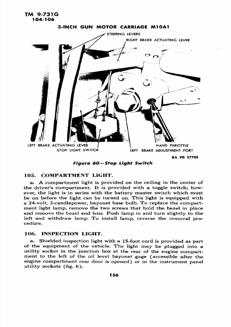
(fig. 60). The stop  light switch is located  in thedriver's compartment in front of the steering  levers. This switch completes the electrical circuit  for the operation of the service and blackout stop lights. The switch  is connected to each steering lever throughadjustable linkage. Both steering levers  must be pulled back beforethe circuit is completed and the stop light functions.

Unscrew the  nut from each link rod  on eachsteering lever. Remove the two cap screws which  hold  the switchbracket  to the transmission plate. Tip the  switch box up, and remove the cover by removing two cap screws. Unscrew the knurled nut fromthe  conduit at the bottom of  the sw itch. Disconnect the four  wiresfrom the switch, and tag for later  identification. To  install the stoplight  sw itch, reverse the steps in the removal procedure. After  installing, adjust the  nut on  each  link rod so  that switch contact is broken when the steering levers are in the forward position.

155

7/29/2019 TM9_731G_1943

http://slidepdf.com/reader/full/tm9731g1943 157/284

TM 9-731G 104-106 

3-INCH GUN MOTOR CARRIAGE M10A1

'STEERING LEVERS

RIGHT BRAKE ACTUATING LEVER

LE FT BRAKE ACTUATING LEVER HAND THROTTLE

STOP LIGHT SWITCH LEFT BRAKE ADJ USTMENT  PORT

RA PD 27705

Figure 60—Stop Light Switch

a. A compartment light is provided on the ceiling in the center ofthe driver's compartment. It is provided with a toggle switch; how

ever, the light is   in series with the battery master switch which must

be on before the light can be turned on. This light is equipped with

a 24-volt, 3-candlepower, bayonet base bulb. To replace the compart

ment light lamp, remove the two screws  that hold the bezel in place

and remove the bezel and lens. Push lamp in and turn slightly to  the

left and withdraw lamp. To install lamp, reverse the removal pro

cedure.

a. Shielded inspection light with a 15-foot cord is provided as part

of the equipment of  the vehicle. The light may be plugged into a

utility socket in the junction box at the rear of the engine compart

ment to the left of the oil level bayonet gage (accessible after the 

engine  compartment rear door is opened) or in the  instrument panelutility sockets (fig. 6).

156

7/29/2019 TM9_731G_1943

http://slidepdf.com/reader/full/tm9731g1943 158/284

TM 9-731G 106-108

ELECTRICAL SYSTEM AND EQUIPMENT

RA PD 77722

Figure 61—Siren

a. A siren, operated by a foot switch (fig. 7) in the driver's compartment, is mounted on the left front fender (fig. 61). To remove

the siren, disconnect the conduit coupling from the connector in the

front armor sloping plate and pull out the plug. Remove the tw o nuts

holding the siren bracket to the fender. Remove the siren. To install,

reverse the above procedure.

The conduits protect the insulation of the wire

against wear and abrasion, and are oil and water spray proof. Radio

interference is cut to a minimum because the conduits provide a continuous grounded circuit over the entire, wiring system. Figure 62shows the conduits fo r the instrument panel wires. These are typical

of the various conduits used throughout the vehicle.

Inspect all conduits for wear and abrasion,

loosening of coupling nuts, and loose or missing conduit support clamps

or brackets. Clean all dirty conduits. In cleaning couplings use dry-cleaning solvent. After cleaning and drying, the threads of each coupling and connector should be cleaned with a wire brush to remove

oxidation which sometimes forms on the threads of aluminum couplings. This oxidation, particularly on the ignition harness fittings,breaks the grounded circuit and causes radio interference.

Replace wires that show broken or hardened

insulation at points of extrusion from a conduit, or that have become

157

7/29/2019 TM9_731G_1943

http://slidepdf.com/reader/full/tm9731g1943 159/284

TM 9-731G108-109

3-INCH GUN  MOTOR CARRIAGE  M10A1

IGNITIO N WIRE  CONNECTION

BLACK OUT HEA D LAMPS CIRCUIT RESISTANCE 

TACHOMETER CABLE CONNECTION INSTRUMENT  PANEL WIRE  CONDUITS

SPEEDOMETER

CONNECTION

SPEEDOMETER TRIP SET-

RA PD 27707

Figure 62—Instrument Panel Case—Back

oil-soaked through failure of a conduit.  If the conduit is badly crushed,replace that section of the  conduit and the  wires contained therein. 

Before disconnecting  any wire from the circuit, fasten a tag  to the

terminal post being worked on, stating the number  of wires, size and

color of the wire,  and where the other end of  the  wire is connected. 

If  this  precaution is not followed, it will be necessary to consult the 

wiring diagrams  (figs. 49  and 54) and trace out the circuit.

(1) REMOVAL. Disconnect the conduit couplings and the enclosed

wires. Remove bracket or clamp supporting the conduit. Attach a piece 

of strong twine to the end of each wire before removing the wire fromthe conduit. The twine can be used in pulling cleaning cloths through

a dirty but otherwise serviceable piece  of conduit.

(2) INSTALLATION. Use only  standard automotive ignition or

primary wire of the same size and color as the wire removed. The wire

may be pulled  through the conduit by means of the heavy twine left

in the conduit when the defective wire was withdrawn. Clean terminal

posts  and wire terminals before connecting any wire  into its circuit.

If the tags or marks on terminals are  missing, consult the  wiring

diagram (figs. 49 and  54). 

Ignition trouble shooting is  cov 

ered under paragraph 36.

(1) GENERAL. In the following discussion the  generator, generator

regulator, and  the battery are  assumed  to be in  operating  condition.

158

7/29/2019 TM9_731G_1943

http://slidepdf.com/reader/full/tm9731g1943 160/284

7/29/2019 TM9_731G_1943

http://slidepdf.com/reader/full/tm9731g1943 161/284

TM  9-731G 111-112 

3-INCH GUN MOTOR CARRIAGE M10A1 

Section XVI

NONELECTRICAL INSTRUMENTS 

Paragraph 

Clock ............................................ IllSpeedometer ......................................  112Tachometer  ....................................... 113 Turret compass  ....................................  114

a. (fig. 6). The clock (8 Jday  type) is located in the left center of the instrument panel. A  reset and rewind knob is locatedat the bottom  of the  dial. 

To  remove the clock,  remove the  instrument  panel (par.  80  h). Remove the two  wing  nuts  from  the clockclamp at  the rear of the panel (fig. 55). Remove  the  clock from  thefront of  the  instrument panel. To reinstall, reverse the sequence of the steps in the removal procedure.

(fig.  6). The  speedometer  is located in the centerof the  instrument panel at the bottom  and  is equipped with a tripmileage  reset.  The speedometer consists of three units, the head,  thedrive  cable, and the drive unit.

Remove the instrumentpanel (par. 80 b). Disconnect the speedometer  cable  by  unscrewing

the  knurled nut at the back of the speedometer head (fig. 55). Dis connect  the trip set from the clip   at the bottom of the instrumentpanel. Remove the  two wing  nuts from the  speedometer clamp  (fig.55), and remove the speedometer head  from  the front of the panel.Reinstall the  head by  reversing the sequence of the steps in  the  removal procedure. 

Unscrew the knurlednut from  the back of the speedometer head and disconnect the  drive cable. Unscrew the  knurled nut holding the cable housing  to  the

speedometer drive gear housing located  on right  rear side  of trans mission (fig. 13), and disconnect the drive  cable. Pull the  cable outof housing from the  instrument panel end. Reinstall  the cable byreversing  the sequence of the steps in the removal procedure.

The speedometerdrive unit is located at the right-hand side of the transmission  (fig. 13).To  remove, unscrew the  knurled nut holding  the drive cable  to the drive unit and disconnect cable. Unscrew the  1-inch nut which secures

160

7/29/2019 TM9_731G_1943

http://slidepdf.com/reader/full/tm9731g1943 162/284

TM 9-731G 112-113

NONELECTRICAL INSTRUMENTS

E-W

N-S

RA PD 27418

Figure 63—Turret Compass

the drive unit to the transmission and remove the drive unit. To

reinstall, reverse the  sequence of the steps in the removal procedure.

(fig. 6). The operation and use of the  tachometer

is explained  in paragraph 5 a (10). The tachometer consists of  three

units, the head, the cable, and the drive unit. 

To remove the head remove

the instrument panel (par.  80 b), unscrew the knurled nut from the

back of the tachometer and  disconnect cable. Remove the two wing

nuts at rear of the instrument (fig. 55) and remove tachometer head

from the front of the panel. To reinstall, reverse the sequence of the

steps in the removal procedure.

To remove the tach

ometer drive cable, unscrew  the knurled nut from the drive unit

located on the left bank of the engine and disconnect the cable. Un

screw the  knurled nut holding the cable housing to the tachometer

head and disconnect the  cable. Pull the cable from the housing. To

reinstall the cable, reverse  the sequence of the  steps in the removalprocedure.

To remove the tach

ometer drive unit (fig. 22) which is located on  the rear end  of theleft-hand camshaft  housing, unscrew the knurled nut which secures

the drive cable housing to  the drive unit. Disconnect the drive cable

housing. Unscrew the 1-inch nut which holds the tachometer drive

unit to  the camshaft housing. Remove  the drive unit. To reinstall,

reverse the sequence of the  steps in the removal procedure.

161

7/29/2019 TM9_731G_1943

http://slidepdf.com/reader/full/tm9731g1943 163/284

TM 9-731G114

3-INCH  GUN MOTOR CARRIAGE  M10A1

114. TURRET COMPASS.

(fig. 63). The  turret  compass is  rubber-mounted

to decrease vibration.

(fig. 63).

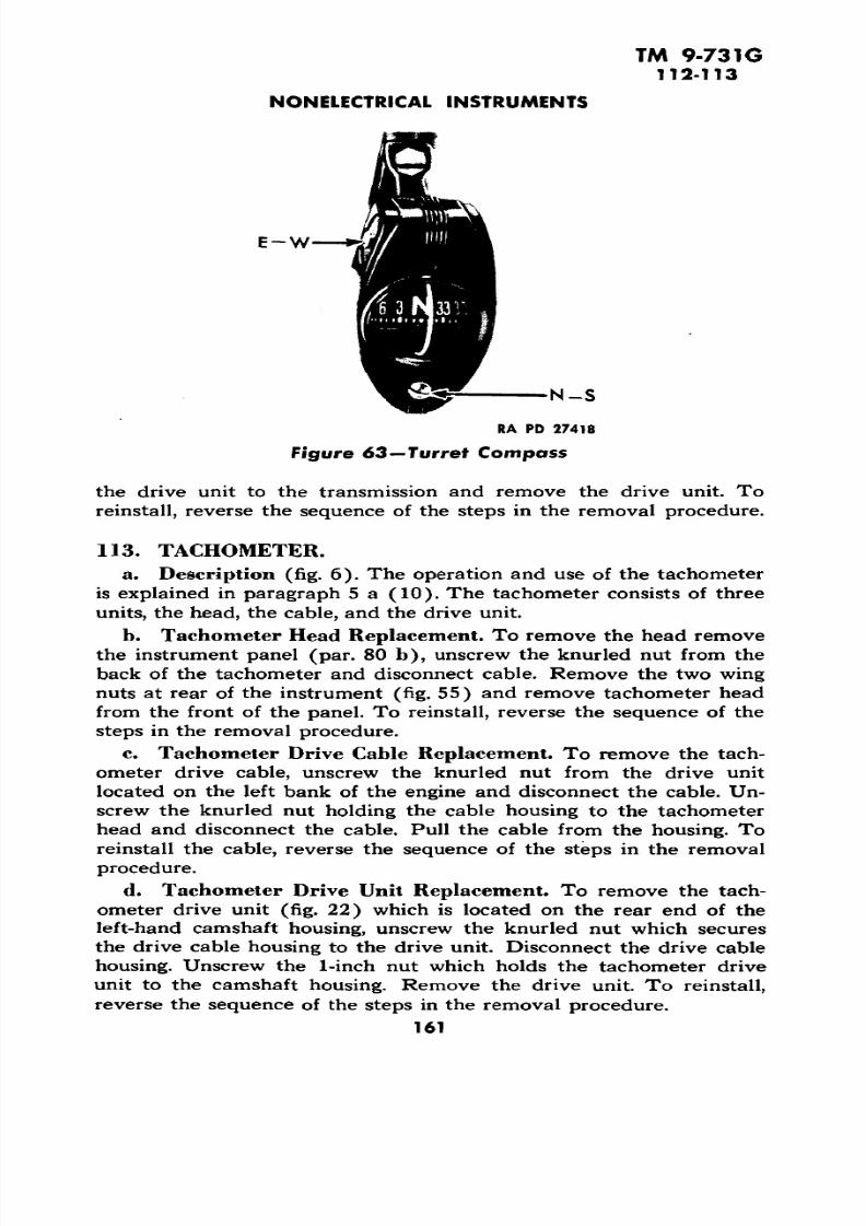
(1) GENERAL INSTRUCTIONS. To  overcome the magnetic effect of

the steel and  electrical equipment in the  vehicle, it  is necessary tocompensate the compass. Use a coin to make adjustments.  Do notuse a screwdriver as  it may be magnetic. Before beginning compensation, be  sure the  compensator  screw  slots  marked  "N-S"  and "N-W"

are  in approximate vertical position. 

(2) ADJUSTING COMPASS.

(a)  Head  the Vehicle North and Adjust. Head the vehicle  north,turn the lower  compensator screw  slot marked  "N-S", slightly if nec

essary, to make the dial read "NORTH" or "SOUTH", no  farther. 

(b)  Head the Vehicle East and Adjust. Head the vehicle east, turnthe upper compensator screw slot marked "E-W", slightly if necessary,to  make  the dial read "EAST", no  farther.

(c) Head the Vehicle

South and 

Adjust. Head the vehicle south,turn  the lower compensator screw  slot marked "N-S", slightly  if nec 

essary, to make the  dial  read "SOUTH".

(d)  Head  the  Vehicle  West and Adjust. Head  the vehicle west,

turn the upper compensator screw  slot marked "E-W", slightly  if necessary, to make the  dial read "WEST".

(3) CORRECTING ADJUSTMENT. If the dial reads "SOUTH" instead of  "NORTH", completion  of  step  (2) will correct  this  condition. Ifthe north  or  south is slightly off, correct by  turning  the lower screw

marked  "N-S". If the east or west is slightly off, correct  by  turningthe  upper  screw  marked "E-W".  Do  not turn upper screw  for  north or south adjustment. Do not turn lower screw for east or west adjustment.

(4)  DRIFT. Do not make adjustments in a steel building or  nearheavy  electrical equipment. In some instances, the magnetic char acteristics of heavy vehicles  are such  that, after the  compass is  com

pensated, the dial is  inclined to drift by  one of the cardinal points.

The condition can be  corrected by turning one  of the compensatorscrew slots one-half turn (approximately  180 degrees) and  recom-pensating the compass.

(5) COMPASS  DRIFT ADJUSTMENT. If the compass is inclined to drift by  the "NORTH" or "SOUTH",  the  upper  compensator screw slot marked "E-W"  should be turned  over and the compass recom-pensated. If the drift is  on  "EAST" or "WEST", turn the  lower  com pensator screw marked "N-S"  one-half  turn  and recompensate thecompass.

162 

7/29/2019 TM9_731G_1943

http://slidepdf.com/reader/full/tm9731g1943 164/284

TM 9-731G115

Section XVIICLUTCH, PROPELLER SHAFT, AND UNIVERSAL JOINTS

Paragraph

Clutch ............................................ 115

Propeller shaft and  universal joints.  .................... 116

Accessory drive shafts and universal joints. .............. 117

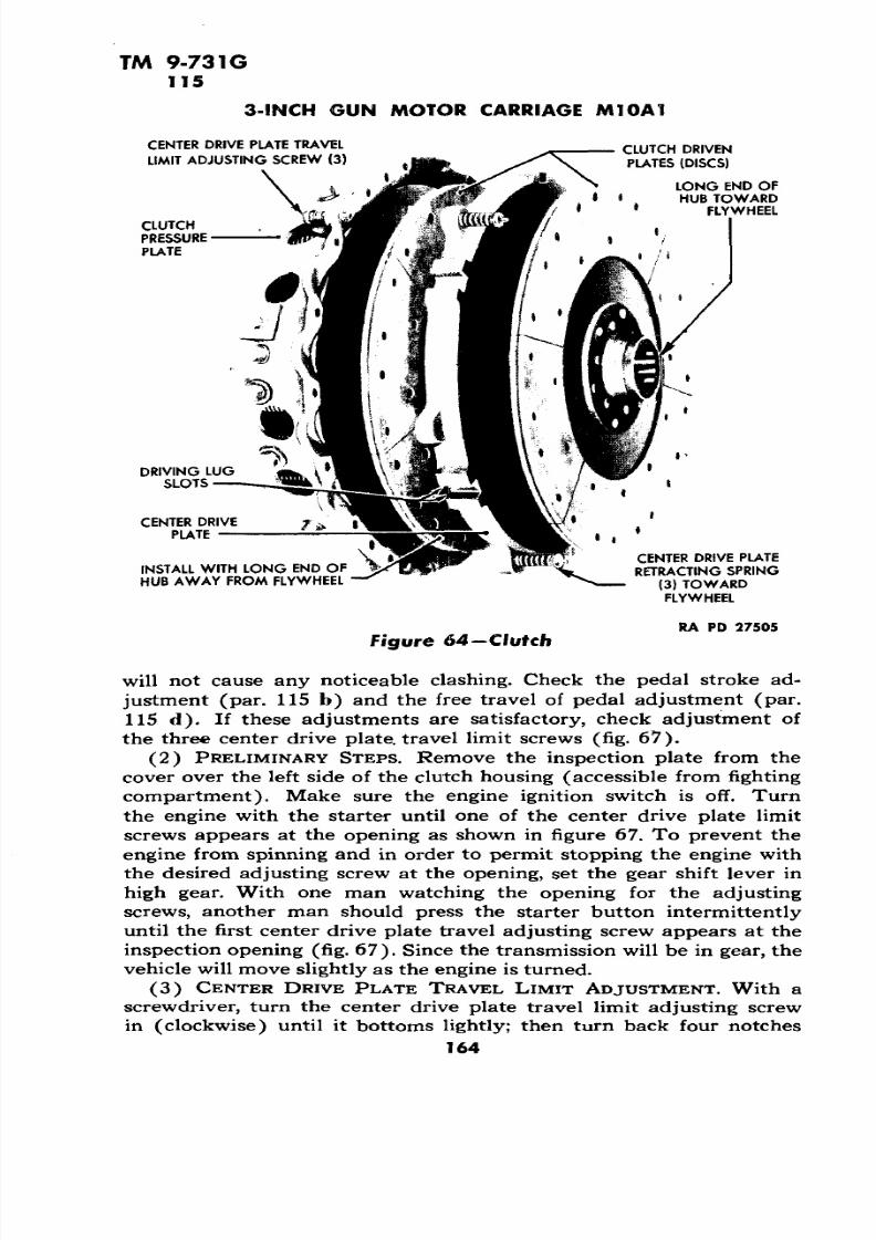
The clutch  is of the double plate standard auto

motive type composed of three major units,the

pressure plate assembly, the center drive plate, and the two driven plates or disks (fig. 64).

The two driven plates have friction  facing riveted on each side. The 

release fork and the re lease levers are mounted on needle roll bearings.

Set the pedal stroke adjustment

stop screw so that the highest point of the clutch pedal pad  is 16 

inches (plus or minus  Vs inch) from the hull floor (fig. 65).

Check the length of the rodrunning  from the clutch pedal to the cross shaft and readjust its

length if necessary. This rod should be 15 V* inches long measuredfrom the center of one clevis pin hole to the other. The length of th isrod may have been changed by some  one who did not know how tomake this adjustment correctly. If this length is not held to 15 Vi

inches, the angle of the  levers  on  the cross shafts will be changedaffecting the operation of the clutch pedal.

The free travel ofthe clutch pedal  is determined by the clearance  between the clutch 

release bearing and the clutch release fork. Clearance must exist be 

tween these parts at all times, otherwise the clutch will  slip  and burnout. Driving with  the  foot on the clutch pedal takes up this clearance with the same resu lt. As the clutch  disk facings become worn, the

pedal free travel decreases. When the free travel of the pedal dropsto less than 2 inches measured  at the pedal pad, it must be adjusted

to 3 l/z inches (fig. 66). The adjustment is made by lengthening orshortening the  rod connecting the clutch cross shaft to the clutch release  lever on the engine by means of  the  clevis on the front end ofthis rod (fig. 65). Lengthening this rod increases, and  shortening this

rod decreases the free play of the pedal. This adjustment must be madethrough the propeller shaft housing.  If unable to get more than 2 

inches  free play, the clutch  plates are  worn and must be replaced.

(1) GENERAL. If, after holding pedal all the way down for a few seconds, the gears  clash when shifting into first  or  release gear, the 

clutch is dragging. NOTE: There is a tendency for the clutch drivenshaft to turn  over  slowly  when clutch is released; this is norm al and

163

7/29/2019 TM9_731G_1943

http://slidepdf.com/reader/full/tm9731g1943 165/284

TM  9-731G115

3-INCH GUN  MOTOR CARRIAGE M10A1

CENTER DRIVE PLA TE TRAVEL CLUTCH DRIVEN LIMIT ADJUSTING SCREW  (3) PLATES  (DISCS)

LONG END OFHUB TOWARD

FLYWHEEL 

CLUTCH 

PRESSURE

PLATE 

DRIVING LUG  SLOTS

CENTER DRIVE PLATE

CENTER DRIVE  PLATEINSTALL WITH  LONG END OF RETRACTING SPRINGHUB AWAY FROM FLYWHEEL (3 ) TOWARD

FLYWHEEL

RA PD 27505 

Figure  64—Clutch 

will not  cause any  noticeable  clashing. Check the pedal stroke ad

justment (par. 115 b) and  the free travel of pedal adjustment (par.

115 d). If these adjustments are satisfactory, check adjustment of

the three center drive plate, travel limit screws (fig. 67).

(2) PRELIMINARY STEPS. Remove the inspection plate from the 

cover over the left side of the clutch housing (accessible  from fighting 

compartment). Make sure  the engine ignition switch is off. Turn

the engine with the starter until  one  of  the center drive  plate limit

screws appears at the opening as  shown in figure 67. To prevent the

engine from spinning and in  order to permit stopping the engine with

the desired adjusting  screw at  the opening, set the gear shift lever in

high gear. With  one man watching  the opening  for the adjusting 

screws, another man should press  the  starter button intermittently 

until the  first center drive plate travel adjusting screw appears at the

inspection opening (fig. 67). Since the transmission will be in gear, the

vehicle will move slightly as the engine is turned.

(3)  CENTER DRIVE PLATE TRAVEL  LIM IT ADJUSTMENT.  With a

screwdriver, turn  the center drive plate travel limit adjusting  screw

in (clockwise) until  it bottoms  lightly; then turn back four notches

164 

7/29/2019 TM9_731G_1943

http://slidepdf.com/reader/full/tm9731g1943 166/284

TM 9-731G115

CLUTCH,  PROPELLER SHAFT, AND UNIVERSAL JOINTS

ADJUST CLUTCH PED AL FREE

TRAVEL AT THISCLEVIS

PEDA! STROKE ADJUSTMENT STOP~SCREW^

RA PD 27510

Figu re 65—Clu tch Pedal Linkage

(counterclockwise). Repeat the above procedure for the two re

maining adjusting screws. If this adjustment fails to  correct the

trouble, repeat the adjustment, backing off the screws five notches

instead of four. If still unsatisfactory, the probable trouble is that the

center plate is binding on the flywheel drive lugs, the pilot bearing inthe flywheel is binding, the clutch disk splined hubs  are too tight on

the clutch shaft, or the driven plates are warped, any of which requires

the  removal of the clutch (par. 115  g).

Stiff. If pedal pressure is too stiff, the

following points should be checked: Check the  position of the clutch

2 INCHES MINIMUM  FREE TRAVEL

DON'T ADJ UST CLUTCH BY CHANGING 1 LENGTH OF THIS SHAFT. SHAFT SHOULD  BE 15</4 INCHES LONG (CENTER TO CENTER)

SE T FREE TRAVEL AT  3% INCHES

WHEN ADJ USTING

AYS INSTALL CLEVIS IN MIDDLE HOLE

PEDAL STROKE ADJ USTMENT STOP SCREW 

I, RA PD 27507

Figure 66—Clutch Pedal Adjustment

165

7/29/2019 TM9_731G_1943

http://slidepdf.com/reader/full/tm9731g1943 167/284

TM  9-731G115

3-INCH GUN  MOTOR CA RRIAGE M10A1

CENTER DRIVE PLATE TRAVEL LIAA1T ADJUSTING SCREW

CLUTCH PRESSURE PLATE

RA PO 28059

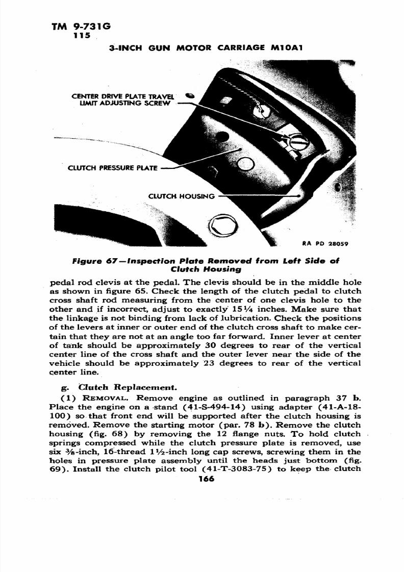
Figure 67— Inspection Plate Removed  from Left Side of Clutch Housing

pedal rod clevis at the pedal. The clevis should be in   the middle hole

as shown in figure  65. Check the length of the clutch pedal to clutch

cross shaft rod measuring from the center of one clevis hole to the

other and if incorrect,  adjust to exactly 15 Vi inches. Make sure that 

the linkage is not binding from  lack of lubrication. Check the positionsof the levers at inner or outer end of the clutch cross shaft to make cer

tain that they are not at an angle too far forward. Inner lever at center 

of tank should be approximately 30 degrees to rear of the  vertical

center line of the cross  shaft and the outer lever near the side of the

vehicle should be approximately 23 degrees to  rear of the vertical

center line.

(1) REMOVAL. Remove engine as outlined in paragraph 37 b.Place the engine on a stand (41-S-494-14) using adapter (41-A-18-100) so  that front end will be  supported  after the clutch housing isremoved. Remove the starting motor (par. 78 b). Remove the clutch

housing (fig. 68) by removing the 12 flange nuts. To hold clutch

springs compressed  while the clutch pressure plate  is removed, use

six %-inch, 16-thread  IVa-inch long cap  screws, screwing them in the

holes in pressure plate  assembly until the heads just bottom (fig.69). Install the clutch pilot tool (41-T-3083-75) to keep the clutch

166

7/29/2019 TM9_731G_1943

http://slidepdf.com/reader/full/tm9731g1943 168/284

TM 9-731G115

CLUTCH, PROPELLER SHAFT, AND UNIVERSA L JOINTS

CLUTCH PILOT

BEARINGENGINE LIFTING

FRONT ENGINE A MOUNT

CLUTCH RELEASE FORK

IS END OF CLUTCH SHAFT RUNSIN CLUTCH PILOT BEARINGIN CRANKSHAFT RA p

Figure 68—Clutch Hou s ing

disk splines in alinement (fig. 69) and also prevent clutch disk fromfalling and possibly injuring your feet. Remove the lock wire from  the

18 cap screws holding the pressure plate to the flywheel, and remove

the cap screws and the pressure plate (fig. 64). Remove center  driveplate from the driving lugs in the flywheel.

(2) INSTALLATION.

(a) Preliminary Steps. See that the  friction surface  of the flywheel is  smooth and clean. Any deposits on the friction surface  must 

be sanded down and the surface cleaned with gasoline or cleaning

fluid. If the clutch shaft pilot bearing is in good condition, repack with

a high melting point grease.

(b) Install Clutch Disks and Center Drive Plate. Place one driven member (disk) in place with long end of the hub toward the  flywheel(fig. 64).  Insert the center drive plate with the retractor spring (fig.64) toward the flywheel making sure the driving  lug slots  fit freely onthe  driving lugs in the flywheel. Install the center drive plate on theflywheel lugs, which will position the retractor springs in line with the

three openings in the flywheel nearest to the three dowel pins  in the

flywheel rim. This will bring the retractor springs in line with the three

adjusting screws in the pressure plate assembly. Using the clutch pilot

167

7/29/2019 TM9_731G_1943

http://slidepdf.com/reader/full/tm9731g1943 169/284

TM 9-731G115

3-INCH GUN MOTOR CARRIAGE M10A1

NOTE RELATIONS OF RETRACTING SPRING TO DOWEL

BEFORE REMOVING CENTER DRIVE PLATE

CLUTCH PRESSURE

l!i| PLATE DOWEL (3)'

CENTER DRIVE PLATE

RETRACTING SPRING (3)

USE SIX %-INCH BOLTS TO COMPRESS 18 CAP SCREWS HOLD PRESSURE

CLUTCH SPRINGS

RA PD 65936

Figure 69—Clutch with Clutch Housing Removed

tool (41-T-3083-75) (fig. 69), slip it through splined hub of the disk

and into the clutch shaft pilot bearing. Remove handle from the pilot

tool. Slip the second disk on the pilot with the long end of its hub

away from the flywheel. This alines both driven members with each

other and the clutch shaft pilot bearing while the pressure plate as

sembly is being attached.

(c) Install the Clutch Pressure Plate. Install the clutch pressure

plate assembly so that the dowel holes line up and install the 18 cap

screws which hold it to the flywheel. Wire the cap screws to prevent

their loosening. Start the wire at the cap screw nearest clutch center

drive plate travel limit adjusting screw, and lock it with the next

nearest cap screw. Proceed with the next 'two until they all have been

locked together in pairs. Remove the six %-inch cap screws used to

hold the pressure plate compressed (fig. 69).

168

7/29/2019 TM9_731G_1943

http://slidepdf.com/reader/full/tm9731g1943 170/284

TM  9-731G 

115

CLUTCH, PROPELLER SHAFT, AND UNIVERSAL  JOINTS 

•o

•sO

inV *«

igI 0)

169

7/29/2019 TM9_731G_1943

http://slidepdf.com/reader/full/tm9731g1943 171/284

7/29/2019 TM9_731G_1943

http://slidepdf.com/reader/full/tm9731g1943 172/284

7/29/2019 TM9_731G_1943

http://slidepdf.com/reader/full/tm9731g1943 173/284

TM 9-731G 117

3-INCH GUN MOTOR CARRIAGE M10A1

LIFT  UP EARS WITH SCREWDRIVER -, 

RA PD 27503

Figure  71—Accessory Drive Shaft

(fig.  71).  Two universal

joints are used on each shaft, one at each end. Four needle roller bear 

ings are provided in each universal joint. Accessory drive shafts are

supplied as an assembly with the universals in place.

172

7/29/2019 TM9_731G_1943

http://slidepdf.com/reader/full/tm9731g1943 174/284

7/29/2019 TM9_731G_1943

http://slidepdf.com/reader/full/tm9731g1943 175/284

7/29/2019 TM9_731G_1943

http://slidepdf.com/reader/full/tm9731g1943 176/284

TM 9-731G118

POWER TRAIN (TRANSMISSION, DIFFERENTIAL, AND  FINAL DRIVE)

RA PD 11073

f igure  72—Power Train Carrier

Remove the two nuts which hold the siren switch bracket and remove

bracket. Wire siren switch bracket, siren switch, and stop light switchup out of the way.

(e) Disconnect Oil Cooler Lines and Speedometer Cable. Discon

nect the transmission oil cooler lines at the fittings on the transmission

housing. Cover the fittings and the oil line couplings with cloth or tape.

Disconnect the speedometer cable from the speedometer drive at  the

top right rear of  the transmission housing by loosening the knurled

nut. Pass the cable under  steering lever cross shaft to clear and tie it

up, out of the way. Tape the end of cable and the opening in the fitting.

(t) Free Power Train Housing. Remove the bolts and lock nuts

which hold the lower edge of power train housing to  the vehicle floor.Lock nuts must be held from inside the vehicle. With a man inside the

vehicle holding the nuts, remove all the bolts from the sides and all

except six bolts in the top, where  the power train is joined to the hull.

The bolts left in the top are to be evenly spaced. The upper corner

bolts on each side are the only bolts with lock washers.  Set the power

train carrier (fig. 73) in place. Raise the jacks until they are solidly

loaded, making certain that each is squarelyin

contact witha flat

sur

face of the  housing. Remove  remainder of the bolts.

(g) Separate Power Train from the Vehicle. Place a  4- by 4-inchblock,  14 inches long, in front of each rear wheel of the  front bogie  to

keep the vehicle from rolling forward when removing the power train. 

Slowly raise each jack, in rotation, until the housing breaks free from 

the hull. Attach a towing cable to each towing shackle on  the power

train; then, with wrecker or other vehicle, pull the power train  slowlyforward and with extreme caution, on a straight line, away from the

175

7/29/2019 TM9_731G_1943

http://slidepdf.com/reader/full/tm9731g1943 177/284

TM 9-731G118-119 

3-INCH  GUN MOTOR CARRIAGE M10A1 

RA   PD 36408

Figure 73—Power Train Carrier in Place

vehicle. CAUTION: Station a man inside the vehicle to see that the

transmission and the gear shift lever, etc. clear and do not catch. Addi

tional clearance for  the levers may be gained by  raising or lowering

the jacks. 

Reverse  the sequence of the  steps

in the removal procedure except the following: .Seal all attaching edges 

of power train with soft-drying mineral putty before installing in

vehicle. Install and line up the  side shims, holding them in place with soft-drying mineral putty. Line up the bolt holes in the power  train

with those in the hull side plates. This operation may require  moving

the power  train slightly forward or backward, or raising or lowering

the jacks. Use drifts to line up the holes; Place four equally spaced

bolts in each side, and four equally spaced bolts  across the  top of

housing to hold power train in line. Install the remainder of the bolts.

The transmission is of the synchronized selective

sliding  gear type having five forward  speeds and one reverse. Syn

chronizers are provided to  facilitate  shifting for all speeds except first

and reverse. Gears for all speeds are in constant mesh. On earlier

vehicles a parking brake, built into the  transmission is operated by  a

lever to the right of the  driver (fig. 7). This brake is to be applied

only when the vehicle is  at a standstill. The parking brake used  on

present vehicles is described in paragraph 5 b ( 7 ).

176

7/29/2019 TM9_731G_1943

http://slidepdf.com/reader/full/tm9731g1943 178/284

TM 9-731G119-120

POWER TRAIN (TRANSMISSION, DIFFERENTIAL,  AND FINAL  DRIVE)

HNAL DR|VECOVER

<*¥

RA PO 36409

Figure 74—Final Drive Unit Removed from Power Train

Remove the power train unit

(par. 118  f). Install transmission lifting eye-bolts (41-B-1586-350)

in the two holes provided at the top of  the transmission housing and

attach a suitable hoist to support the weight of the transmission. Re

move  the 19 nuts which secure the transmission housing to the differ

ential housing and remove the transmission assembly. To install trans

mission, reverse the sequence  of the removal operation, using new

gaskets. NOTE: When a new transmission  is to be installed, installa

tion will be made by ordnance maintenance personnel.

a. The differential permits one track to move  slower or faster than

the other on turns. The operator can cause either track to run slowerthan the other by pulling back on  the steering lever corresponding  to

the direction of the desired turn for steering the vehicle. When either

steering brake lever is pulled back,  it tightens the brake bands and

slows or stops  the brake drum  on that particular side. This slowing or

stopping of the brake drum and its compensating shaft slows down

(but cannot stop) the track on the side of which the steering brake isoperated, and causes a corresponding increase in the speed of the other

track, so that the vehicle turns toward the side of the slower track.

177

7/29/2019 TM9_731G_1943

http://slidepdf.com/reader/full/tm9731g1943 179/284

7/29/2019 TM9_731G_1943

http://slidepdf.com/reader/full/tm9731g1943 180/284

TM  9-731G122-123

POWER TRAIN (TRANSMISSION, DIFFERENTIAL, AND FINAL DRIVE)

RA   PD 36401 

Figure 75—Brake Adjustment

and back to  the transmission, through tubes  running under the pro

peller shaft housing, on the hull floor.

(fig. 9). To remove transmission

oil cooler, disconnect  oil inlet and outlet tubes at the oil cooler. Re 

move the four cap screws which hold the cooler guard and remove the

guard. Remove the four bolts from the brackets at each end of the oil

cooler and remove the oil cooler unit. To -install the transmission oil

cooler, reverse the removal procedure, making sure that the felt is in

place between  the bulkhead and cooler before fastening  the cooler tothe bulkhead.

The  tubes running to

the oil cooler are provided with standard fittings that permit easy re

placement of either line. When installing new lines, make sure  that

the new line has the same contour as the original contour of the line

removed.

The use of the steering brakes is outlined in paragraph 5 b (6). When unusual noises are heard when the brakes are

applied, the brake shoes must be examined and replaced if required to

prevent scoring of the brake drums. When the free travel of the steering levers has increased to 8 inches, minor adjustment of the brakes

is necessary. If this minor adjustment fails to establish good brakes,

make the major brake adjustment (par. 123 d). If the major adjust 

ment fails to establish good brakes, replace the brake shoes (par.

123 e).

179

7/29/2019 TM9_731G_1943

http://slidepdf.com/reader/full/tm9731g1943 181/284

TM  9-731G123

3-INCH  GUN MOTOR CA RRIAGE M10A1

BRAKE ADJ USTING 

NUT

ROD

RA PD  36400

Figure 76—Details of Brake Shoe and Brake  Shaft

la. Check  Steering Lever  Free Travel. With the vehicle  stopped,measure the distance the top of each steering lever can be pulled back

with the finger tips. Measure only the free travel that takes  up the

clearance between the brake shoes and the drum. If this free travel

exceeds 8 inches, adjust the brakes  (par. 123 c). When the vehicle  isequipped with  new brake linings, and the steering brake levers, link

age, and the steering brakes are in correct adjustment, each lever has

a  minimum free travel of approximately 4 inches. As brake  linings

wear, the free travel will increase.

c. Steering Brake Adjustment (Minor). Remove the brake ad 

justment port caps  and gaskets  (fig. 80). Insert wrench (IVs-in.

socket, extension, with ratchet handle)  into the port (fig . 75) and

take up brake adjusting nut (fig. 76), turning clockwise the neces

sary number of  notches to adjust steering levers to a  free travel of

4 inches. If a free travel of 4 inches cannot be obtained, make a major

adjustment as outlined in paragraph 123 d. Remove the socketwrench. NOTE: Be careful that socket does not come off  extension

and drop into differential housing.  Check the steering brake levers

180

7/29/2019 TM9_731G_1943

http://slidepdf.com/reader/full/tm9731g1943 182/284

7/29/2019 TM9_731G_1943

http://slidepdf.com/reader/full/tm9731g1943 183/284

TM 9-731G 123 

3-INCH GUN MOTOR  CARRIAGE M10A1

RA PD 4861

Figure  77—Adjusting Centering Bolt 

(7) ADJUST STEERING LEVER  STOP  SCREWS. Loosen  the  lock nuts

on the steering lever  stop screws. Adjust the left steering lever stop 

screw so that rear edge of the left steering lever is opposite the clevis

pin  hole in  the left brake actuating lever. Adjust the  right steeringlever stop  screw  so that the right steering  lever  is lined up with  the 

left steering lever. Tighten both  stop  screw lock nuts.

(8) ADJUST  STEERING  LEVER CONNECTING RODS.  With  steering

levers  forward against  their  stops, adjust the  devise's  on the  steering

lever connecting rods  (fig . 80) so that the clevis pin holes in the 

clevises are in line  with the clevis pin  holes in the brake shaft  levers

(levers to be pressed  downward). Line up  the lever clevis pin holes

and connecting rod  clevis pin holes, then  unscrew  the  clevises three

full turns to increase the  length of the rods. Line up holes in actuating

levers and connecting rod  clevises. Install  clevis pins  and cotter pins. 

This  additional length of each steering lever connecting rod will give

the  necessary clearance between  the  brake  linings and the  drums.

(9) TEST STEERING LEVERS FOR  EQUAL TRAVEL.  A  notch or two 

on either or both of the steering brake adjusting  nuts, in either direc

tion, is permissible to effect equalization. An  approximately correct

adjustment will have been obtained when the brake  shoes just engage

182

7/29/2019 TM9_731G_1943

http://slidepdf.com/reader/full/tm9731g1943 184/284

TM 9-731G123

POWER TRAIN  (TRANSMISSION, DIFFERENTIAL, AND FINAL DRIVE)

RA PD 4863

Figure  78—Removing Link Pin   from Cam

the brake drums when the steering levers  are  pulled back to a nearly

vertical position. Install both steering brake cover  plates and gaskets.

Make sure gaskets are in good condition. Refill power train with

lubricating oil, following instructions  in  Lubrication Guide (par. 24).

(1) REMOVAL. Drain the power train unit (par. 118 d). Discon

nect both steering lever connecting rod clevises at the left side of

the differential housing. Remove the clevis pin from  the lower yoke of

the brake shaft actuating  lever on the  right side of  the differential

housing and disconnect the link. Remove the steering brake  cover

plates and gaskets (par. 123 d (2) ) and wipe out the housing. Loosen

the  lock nut and turn down the centering bolt (fig. 77) (1-in. and 

183

7/29/2019 TM9_731G_1943

http://slidepdf.com/reader/full/tm9731g1943 185/284

7/29/2019 TM9_731G_1943

http://slidepdf.com/reader/full/tm9731g1943 186/284

TM 9-731G124

POWER TRAIN (TRANSMISSION, DIFFERENTIAL, AND FINAL DRIVE)

RA PD 4864

Figure 79—Pulling Brake Shoe Out of Housing

185

7/29/2019 TM9_731G_1943

http://slidepdf.com/reader/full/tm9731g1943 187/284

TM 9-731G 124

3-INCH GUN  MOTOR CARRIA GE M10A1

ff

o0)

0

t)JtstoD>

§o81

186

7/29/2019 TM9_731G_1943

http://slidepdf.com/reader/full/tm9731g1943 188/284

TM 9-731G124

POWER TRAIN (TRANSMISSION, DIFFERENTIAL, AND FINAL DRIVE)

the cotter  pin and washer from  the parking brake lever shaft and

remove  the shaft and lever  (fig. 80). Remove the cap screws which

hold the parking brake housing to the transmission. Pull the housing

off the brake shoe  spline and remove the housing. Remove the brake

shoe cone.

(2) INSTALLATION. Reverse the sequence of the steps in the

removal procedure, but, select a position on the spline where the brake

shaft spacer will mesh into the recess in the spline, when installing

the housing over the brake shoe spline.

(3) REMOVAL OF LATER TYPE PARKING  BRAKE MECHANISM  (fig.8). Push the quadrant pedal all the way down. Remove the  lock wireand  the cap screws which hold the quadrant assembly (fig. 8) to the

floor. Remove the  quadrants. To reinstall, reverse the sequence ofthe steps in the removal procedure.

c. Adjustment of Earlier Type (fig. 80). Remove the 

parking brake lever with the brake shaft lever attached, by withdraw

ing the cotter pin  from the shaft. Slide the  shaft out of the  adjusting

nut of the toggle link and  remove the washer and  spacer. Screw the 

adjusting nut outward  (counterclockwise), to lengthen  the link anddecrease the clearance between the brake lining and the  drum. The

adjusting nut must be given a complete turn, or several complete turns,

in order  to bring the oil hole on top. Reinstall the brake shaft, spacer,

washer, and cotter pin, and test adjustment. Readjust as necessary toeffect complete contact between the shoe and the drum when the lever

is  in the locked  position. When the proper adjustment has been

attained,  lock the brake by pulling  the lever  all the way back, then

loosen the clamping bolt at the bottom of the brake lever, move the

lever to vertical or slightly forward position, and tighten the clampingbolt. Secure the nut  on the bolt with  a cotter pin.

187 

7/29/2019 TM9_731G_1943

http://slidepdf.com/reader/full/tm9731g1943 189/284

TM 9-731G125-126

3-INCH GUN MOTOR CARRIAGE M10A1

Section  XIX

SUSPENSION AND TRACKS

Paragraph

General description ................................. 125

Inspections ....................................... 126

Drive sprockets .................................... 127

Bogies ............................................ 128 

Tracks ........................................... 129

Idlers ............................................ 130

Installation  of grousers .............................. 131

a. Six two-wheeled rubber-tired bogies, or suspensions, bolted to

the hull, support the vehicle on  volute springs. The tracks are driven

by sprockets at the front of the vehicle. Two idlers are mounted on

eccentric shafts at the rear end of the hull. These shafts are made

eccentric to provide for the adjustment of track tension. The weight of

the upper part of the track, between the idler  and the sprocket, is

carried by three steel track support rollers mounted  on  brackets

attached  to the bogie brackets.

Tracks  and suspensions should be in

spected at every opportunity in order to detect in the early stages anyfault that, if not corrected, would lead to serious impairment of the

efficiency of the vehicle. The best preventive maintenance is to keep

the entire track and suspension system as clean as possible, and free

from stones, sticks, and other solid debris. At every inspection, the fo llowing routine must be carried out.

(1) TRACK TENSION. If the track  shows a noticeable sag between 

the track support rollers, the track should be adjusted (par. 129 b). (2) TRACK  CONDITION. Check the end connectors for wear and

bent  or broken guide lugs.  Inspect all wedges and nuts  for presence

and tightness. Check for bottomed wedges; if the clearance between

the wedge and  connector is less than one thirty-second inch, install a

new  wedge. If grousers are being used, inspect their condition and

tightness. Inspect for dead track blocks (fig. 81) and  replace them

(par. 129 c). A dead  track block  must be in the top section of the

track to be detected, so the vehicle must be  moved several times  to

188

7/29/2019 TM9_731G_1943

http://slidepdf.com/reader/full/tm9731g1943 190/284

TM 9-731G 126-127

SUSPENSION AND TRACKS

DEAD TRACK BLOCK

RA PD 12481

Figure 81—Dead Track Blo c k Dropping Out of L ine on Top

of Track

make a complete inspection. During this check, the inside  wedge andconnectors must also be inspected.

(3) SPROCKETS. Check for sprung or worn teeth. Check cap screws

and hub nuts for tightness.

(4) BOGIE WHEELS. Check the condition of the tires on all wheels.

Look for evidence of the outer spacer turning (tighten gudgeon nut).

Check gudgeon nuts and cotter pins for presence. Check grease fittings

and relief valves (replace if damaged or missing).

(5) BOGIE ASSEMBLIES. Check  for broken or weak volute springs.Inspect for worn wheel arm and lever rubbing plates  (fig. 82 ). Inspect

bogie bracket for presence of bolts, nuts, and lock wire.

(6) SUPPORT ROLLERS. Look fo r evidence of rollers not turning.

Free all rollers by cleaning out mud, rocks, etc. Check grease fittings 

(it is essential that all rollers turn freely, since inoperative rollers will

develop flats).

(7)  IDLERS. Check idler cap retaining screws and grease fittings

(fig. 91).

(fig. 83). The sprocket and  hub assembly is

formed by bolting two sprockets to a hub, which is attached by studs

and nuts to the drive flange of the final drive shaft. Sprocket and hub

assemblies, interchangeable as units, should be transposed between the

right and left final drive shafts when the sprocket teeth  have become

appreciably worn on their flanks from  long use  in one direction.

189

7/29/2019 TM9_731G_1943

http://slidepdf.com/reader/full/tm9731g1943 191/284

TM 9-731G 127-128

3-INCH GUN MOTOR CARRIAGE M10A1

BOGIE ROCKING LEVER

BOGIE LEVER RUBBING PLATE

BOGIE LEVER RUBBING PLATE

BOGIE ARM RUBBING PLATE

SUSPENSION ARM

RA   PD 65938

(fig. 83). To re

move the sprocket and hub assembly, slacken the track (par. 129 b).Disconnect the track below the sprocket  (par. 129 d). Remove the

eight hub  retaining nuts. Remove  the hub assembly. To reinstall,

reverse the sequence of the steps in the removal procedure.

The  six bogies are the vehicle supporting units,

sometimes called suspensions. Vertical movement of the wheels, as

they pass over irregularities in the ground surface, is transferred to the

supporting arms and levers, and is absorbed by volute springs, two ineach bogie.  Wear between the wheel arms and the spring levers istaken by upper and lower rubbing plates (fig. 82), which can be re

placed when worn. On the rear side of each bogie bracket is mounteda single steel roller to support and guide the track between the idler

and the sprocket. Whenever bogie wheels are changed, retainer (seal)

B132704AB  and spacer (adapter) B153965 will be installed when

available (par. 128 d).

Lubrication of the wheels and the track-supporting rollers  is through pressure gun fittings. Relief valves are pro

vided to prevent damage to  the grease retainers (sec. VI).

190

7/29/2019 TM9_731G_1943

http://slidepdf.com/reader/full/tm9731g1943 192/284

TM 9-731G 128

SUSPENSION AND TRACKS

DRIVE SPROCKETS

RA PD 27475

Figure 83— Sprocket and Hub Assembly

( 1 ) REMOVAL. To remove bogie wheel, raise the wheel by means of

one of the following two methods: Place the bogie wheel lift (41-D-

1463) (fig. 84) on the track under the suspension arms to be lifted.

Carefully drive the vehicle forward or backward (depending on which

bogie wheel is to be lifted) until the bogie lift is vertical and the bogie

wheel has been lifted, or place two 5-ton hydraulic jacks on the track

directly under the center of each end of the spring seat plate, and jack

up the spring seat until all load is removed from the wheel arms (fig.

85). Remove the cotter pin from the nut on the inner end of the wheelgudgeon and remove the gudgeon nut (2 3/s-in. gudgeon wrench). Re

move the gudgeon pin. Two types of gudgeon pins have been used and

are removed as follows: Gudgeon pins having a threaded hole on the

outer end can be pulled by screwing the slide hammer bogie gudgeon

puller (41-P-2957-33) (fig. 84) into the threaded hole and pull the

gudgeon. To remove the gudgeon pin with no hole provided for the

puller, drive on the inner end of pin with drift. Remove the wheel from

between the arms.

191

7/29/2019 TM9_731G_1943

http://slidepdf.com/reader/full/tm9731g1943 193/284

TM 9-731G 128

3-INCH GUN MOTOR CARRIAGE M10A1

RA PO 65939

Figure 84—Pulling Wheel Gudgeon to Remove Bogie Wheel

(2) INSTALLATION. Move the wheel into place between the two

arms. Raise the arms and aline  their holes with the hole  in the wheel.

Start the wheel gudgeon through the outer arm  and into the outer

spacer, grease seals, .and outer bearing of the wheel. Line up the centerspacer by means of an alinement bar inserted from the inner side of

the wheel, and tap the gudgeon into the spacer. Then drive the gudgeon

through far enough to allow the key slot in the gudgeon to be lined up

with the slot in  the arm. Install the key, and drive the gudgeon in the

rest of the way. Install and tighten the gudgeon nut on the inner end

of the gudgeon and secure with  a cotter pin.

(1) REMOVAL. Remove bogie wheel (par.  128 c). Pull out the twoouter spacers.  Turn the wheel on its side on blocks and, with  a brass

drift (41-D-1463) through the upper side of the wheel, drive the bear

ing and grease seals out of the lower  side. (It will be necessary to

move the inner spacer away from the bearing in order to seat the

drift on the outer race of the bearings. Keep moving the drift around

the entire circumference of the bearing outer race, in order to drive it

out evenly and with no damage to the bearings.) The spacer will drop

out when the bearing is removed. Turn the wheel over and remove the

192

7/29/2019 TM9_731G_1943

http://slidepdf.com/reader/full/tm9731g1943 194/284

TM 9-731G 128

SUSPENSION AND TRACKS

other bearing and grease seals by the same method. Clean the bear

ings and inspect for wear, cracked rollers, or flat spots.

(2) INSTALLATION. When the bogie wheel grease seal and bearingare being replaced, be certain to install the new type retainer (seal)

B132704AB and spacer (adapter) B153965. Do not reinstall seal

A244899, spacer B197500, and backing plate B197501, as they are

obsoleted upon the availability of the new seal and spacer listed above.

(a) Install the bearing by starting it by hand and tapping it lightly

into place with a brass drift (41-D-1463), working around the outer

race. Be sure the bearing is squarely seated against the shoulder in the

wheel, to allow room for the grease seals. End play of bogie wheels

equipped with tapered roller bearings should be checked whenever

rawhide seals are installed; play should'be from 0.003 to 0.021 inch.

If end play of tapered roller bearings exceeds 0.021 inch, or in case of

bearing failure, tapered roller bearings will be replaced with ball bear

ings CABX3AL when available.

(b) A rawhide type seal should be soaked thoroughly for 30 minutes

with engine oil, or neat's-foot oil, before installation. Seals must be kept

in waterproof wrappers, away from moisture, extreme heat, or cold.

Sand or dirt must not be allowed to get on the seal to serve as anabrasive. Coat the sealing surfaces well with grease before assembly,

and place a liberal supply of grease between the retainers. Use the

proper drift or a rawhide hammer to carefully seat the seal. Be sure

the seal is placed squarely in the opening and not cocked or bent.

When a seal is bent or twisted during installation, it must be discarded

and another new one used. The sealing lips of the seal must be point

ing to the outside of the bogie wheel, to realize the primary purpose

of preventing entry of dust and mud into the bearing assembly. After

installing outer spacer and seals, turn the wheel over and install center

spacer, bearing, oil seals, and spacer as described above. If the sealing

surface of the spacer is etched, nicked, rough, or untrue, a new part

should be installed to insure a smooth sealing surface.

(fig. 85).

(1) REMOVAL. Place two 5-ton jacks beneath springs. Position the

jacks on the track so that the head of each jack is in the center of each

end of the spring seat plate. In placing the jack, arrange the blocking

so that the jack plunger will be nearly at the upper end of its travelwhen the thrust of the springs is taken up, in order to permit a greater

lowering travel later (fig. 85). Jack up seat plate. Raise each jack

until the thrust of the springs has been taken up. Straighten the ears of

locking plate, remove the two locking cap screws, and loosen the center

cap screw that secures the center gudgeon pins in the bogie bracket

(fig. 85). Remove the bogie gudgeon pins (par. 128c (1)). When the

pins are pulled out, the bogie arms and gudgeon spacers will drop.

193

7/29/2019 TM9_731G_1943

http://slidepdf.com/reader/full/tm9731g1943 195/284

TM 9-731G128

3-INCH GUN MOTOR CARRIA GE M10A1

-HY DRAULIC J ACKS-- RA PD 65940

Figure 85—Changing Volute Springs

Lower the jack with the spring seat plate and springs. If the jack has

not sufficient travel to decompress the springs, push two bars through

the gudgeon pin holes, and lower the spring seat plate on to the bars. 

Remove the blocking, or lower the adjustable screw on the jack, and

again raise the plate off the bars with the jack. Remove the bars, and

continue to lower the jack and decompress the spring. If the spring

seat plate and springs  do not drop out on removal of the jack, free

them with a hammer or wood block.  NOTE: Whenever a new volute

spring is required, install two new springs, never one old and one new

spring.

(2) INSTALLATION. Place the springs and spring seat plate in posi

tion and raise with the jacks until the springs are compressed  sufficiently. Aline the bogie  arms and spacer plates and install the

gudgeon pins, making sure that their grooves are on the side to permit

installation of the locking cap screws. Install the gudgeon locking cap 

screws and secure the lock plate to the cap screw heads. Lower and

remove the jacks, allowing the bogie levers to resume their normal

position on the wheel arms.

To remove

194

7/29/2019 TM9_731G_1943

http://slidepdf.com/reader/full/tm9731g1943 196/284

TM 9-731G 128-129

SUSPENSION AND TRACKS

the track support roller and bracket, remove the lock wires and the

four cap screws securing the track skid to the top of the bogie frame,

place a jack between the front bogie wheel and track, and raise track

to remove its weight from the bogie wheel. Remove the track skid.

Remove the lock wire and the six cap screws holding the roller bracket

to the bogie frame and remove roller and bracket assembly. Remove

the lock wires and the four cap screws securing the roller shaft to the

bracket and lift roller and bracket. To reinstall, reverse the sequence

of the steps in the removal procedure.

(1) GENERAL. Each track has 79 separate shoes, or blocks, which

may be rubber-covered, or all steel. Two parallel pins run through each

block, and project at both ends. Steel connectors fit over the ends of

the adjacent pins of adjoining blocks, linking the blocks on both sides

to form a continuous track. Each track pin has doughnut-shaped

rubber spacers vulcanized to fit. These spacers, when the pin is pressed

into the steel frame of the track block, form a flexible cushioning bond

between the pin and the block. The connectors are held on the pins by

wedges, which fit against milled flats on the pins. These flats face out

ward, and are inclined at an angle of 7 degrees to the tread surface

of the block. The wedges are tapered at 15-degree angles on each face,

so that when they are pulled up between the two pins by the bolt (an

integral part of the wedge), they cause a 16-degree angle between

adjacent blocks. This angularity tends to make the track curve around

the rear bogie, the idler, and the sprocket. Flared perpendicular

projections on the end plates serve as guides to keep the track in

alinement and to hold it on the bogie wheels, idlers, track support

rollers, and drive sprockets. The sprocket teeth engage the track

between adjacent connectors. Since the condition and effectiveness ofthe track can definitely limit or increase the performance ability of

the vehicle, it is essential that it is inspected, adjusted, and maintained

in the best possible condition. Several types of track block are used

(par. 129 a (2), and (3)).

(2) RUBBER BLOCK TYPE. Two designs of rubber blocks are in

use, the first having the same thickness of rubber on both sides, the

second having a greater thickness of rubber on the tread (ground

contact side) than on the bogie wheel contact side. Shoes of the lasttype must be replaced when further wearing away of the tread would

expose the tubular sections of the inner steel link to the risk of being

dented or deformed. Damaged shoes must be replaced immediately.

Shoes of the first type (same thickness on both tread and bogie side),

whose tread rubber has worn thinner than the rubber on the inner

side may be reversed (par. 129 d). This type of shoe will be replaced

when the rubber on the second side has worn to the extent that wear

in the steel links is imminent.

7/29/2019 TM9_731G_1943

http://slidepdf.com/reader/full/tm9731g1943 197/284

TM 9-731G129

3-INCH GUN MOTOR CARRIA GE M10A1

STRAIGHT EDGE

INCH SAG BETWEEN ROLLERS

RA PD 27 482

(3) ALL-STEEL TYPE. Steel shoes are  formed with one long lug atthe toe of the block (the  forward edge when the block is on  the

ground) and two short lugs at the heel (rear edge). Tracks will nor

mally be  installed, when new, with the long lugs  forward when the

shoes  are on the ground; but the entire track may be turned end-for-

end when it is necessary (par. 129 g).

(fig. 86).

(1) METHOD. The track should be checked daily for correct ten

sion. If a  pronounced sag is present,  tension should be restored toeliminate the possibility of the tracks being damaged or thrown off.Figure 86 shows the correct track adjustment. Track tension is ad

justed  by turning the spindle of the eccentric idler shaft (fig. 87).

(2) SETTING THE ADJUSTMENT. Partially back out (do not re

move) the two end (clamping) bolts of the three bolts on the rear

of the split housing (fig. 87). Turn  down the spreading bolt to open

up  the housing. NOTE: Because this bolt has a left-hand thread, it

also is turned counterclockwise to spread the split housing. In loosen

ing or  tightening the spindle, the spreader bort is turned in the samedirection  as the clamping bolts. Raise the spring clip at the end of 

the housing, loosening its screw if necessary, and tap the  collar plate

all the way  off the serrations on the spindle to the position shown in

figure 87. It may be necessary to take the load off the collar by using

the  idler adjusting wrench on the hexagon end of the spindle, as in

tightening the track. Tighten or loosen the track  by using the idler

adjusting wrench (41-W-640-400) on the hexagon at the end of thespindle. To tighten, raise the handle of the wrench (using a pipe for

196

7/29/2019 TM9_731G_1943

http://slidepdf.com/reader/full/tm9731g1943 198/284

TM  9-731G 129

SUSPENSION  AND  TRACKS

ADJ USTINGNUT

COLLAR

PLATE

cup SERRATIONS ON

IDLER SPINDLE

CLAMP INGBOLT

SPLIT 

HOUSING

IDLER  ADJ USTING WRENCH SPREADING BOLT L. H. RA PD 36420

Figure 87—Tightening Track wifh Idler Adjustment

leverage, or a jack under the end of the handle) until the track shows

a sag of not more than 3A inch midway between the  support rollers.Sag can be measured from a straight edge placed on the track between

the support rollers (fig. 86). CAUTION: Tracks that are too tight

will cause a  serious reduction in the performance of the vehicle.

(3) LOCKING THE ADJUSTMENT.  Drive the collar plate back on the

serrations of the spindle and lock it in place with the spring clip.  Back

out the center spreader bolt by turning it clockwise.  (Make sure thatit does not project into the split of the housing.) Pull both  outside

clamping bolts up tight, and tighten down the spreader bolt until it 

binds sufficiently to hold it from working loose.(fig. 88).

(1) DEFINITION.  A dead track block is one in which  the rubber 

bond between the pin and the metal frame of the block has failed, leav

ing the pin free to turn. Dead blocks are easily recognizable (fig. 81)

and should be replaced immediately as they may result in a broken

track.

(2) REMOVAL. Move the vehicle so that block to be  replaced is

197

7/29/2019 TM9_731G_1943

http://slidepdf.com/reader/full/tm9731g1943 199/284

TM 9-731G129

3-INCH GUN MOTOR CARRIAGE M10A1

.„«*

Figure 88 — Replacing Dead Track Block

midway between the idler and the rear bogie wheel. Set the parking

brake. Release the track tension (par. 129 b).  Remove the wedge nuts

on the two inside and  two outside connections  (fig. 89) attached to

the block to be replaced. Tap out the wedges, being careful not to in

jure  threads. Drive the two inside and two outside  track connectors

halfway off the pins of the track block  to be removed. Between the

track connectors and the blocks, insert the curved fingers of the

Simplex jack  track  connecting fixture (41-F-2997-85 or 86) over the

exposed pins in the two track blocks immediately adjacent to the

dead track block  (fig. 88). The upper surfaces of the track connecting

fixture  plates must fit snugly against the tread surfaces of the track

blocks. Insert the handle in jack ratchet fitting. Pull up the track until

the  fixture is securely solid, then knock off the four loosened connec 

tors. Figure 88 shows dead track block with outside track connectors

removed, and inside connectors still  in place, and the holding block.

198

7/29/2019 TM9_731G_1943

http://slidepdf.com/reader/full/tm9731g1943 200/284

TM 9-731G 129

SUSPENSION AND TRACKS

X.

CONNECTOR NUT

RA PD 12460

f igure 89—Removing Track Wedge Nut

(3) INSTALLATION. Place the new  track block in position. Install

the track connectors driving them halfway on to pins, operating the

jack if necessary to position the pins. Back off the jack and remove the

track connecting fixture. Drive connectors the rest of the way on. Install the wedges in  connectors drawing them tight. NOTE: Before  in  stalling, inspect wedges and nuts, and replace if worn or damaged.

When rubber track blocks are to

be reversed (turned over) or several blocks must be replaced, the track

should be removed from the vehicle. Note that the track is broken at

the front of the tank, between the sprocket and the front bogie wheel,instead of at the  rear, as for the replacement of a single block. Break

the track just below the sprocket. Move  the upper  part of the trackto the rear over the drive sprocket by turning the sprocket with a bar,

and pull the track back off the rollers. Again break the track this time

just in back of the rear bogie. Reverse the blocks of the part of the

track just removed by removing all the connectors and turning each

block over. To equalize the wear on the cormectors, turn them end-

for-end and install them on the opposite side of the track. Connect this

reversed section of the track to the section underneath the bogie

199

7/29/2019 TM9_731G_1943

http://slidepdf.com/reader/full/tm9731g1943 201/284

TM 9-731G

129

3-INCH GUN MOTOR CA RRIAGE M10A1

RA PD 36421

Figure 90—Joining Ends of Track at Front Sprocket

wheels and tow the vehicle back onto the section already reversed.

Disconnect the remaining section of the track and reverse the blocksand connectors. Again connect the two sections of the track. Tow the

vehicle onto the front section, and roll the rear section over the idler,

support rollers, and sprocket, using a bar to turn the sprocket (par.

129 g). Connect the two ends of the track (fig. 88).

Because conditions under

which a track may be thrown vary greatly, no one procedure can be set

down as the best possible method for its replacement. The following

procedure can be  used under the worst conditions, and can be modified for different situations. Break the  track underneath either the

idler or the sprocket, depending on which end of the track has the least

twist. Tow the vehicle completely off the track. Roll up the track and

move  it to the front or to the rear of the vehicle, depending on which

has the best ground for towing the vehicle back onto the track. Lay

the track out with the "end  at the nearest bogie, with several blocks

sunk in a trench dug deep enough so that the bogie can roll onto thetrack without having to climb. Tow the vehicle on to the track until

200

7/29/2019 TM9_731G_1943

http://slidepdf.com/reader/full/tm9731g1943 202/284

TM 9-731G 129

SUSPENSION AND TRACKS

the leading bogie wheel is about 16 inches from the end of the track.

Roll the track up over the idler and support roller, and around the

sprocket, using a bar to turn the sprocket. NOTE: Sometimes thetrack may be thrown in such a manner that the proper manipulation ofthe vehicle, and the use of blocks, make it possible to work the track

back on again.

(1) REMOVAL. To install a new track when the old track is still onthe vehicle, break the old track under the sprocket and roll the track

back off the sprocket and rollers, using a bar to turn the sprocket. Lay

out the track in front of the old one and connect the two. Tow the

vehicle onto the new track until the front bogie wheel is about 16

inches from the end of the track. Disconnect the old track, and roll

the new one up over the idlers, the track support rollers and around

sprocket, and connect the ends (fig. 90).

(2) INSTALLATION. To install a new track when the old track is offthe vehicle, proceed as in paragraph 129 e.

(1) GENERAL INSTRUCTIONS. To equalize the driving wear on the

track connectors, and thus lengthen the operating life of the track, theentire track can be turned end-for-end, shifting the driving wear to the

other contact surfaces of the connectors. With good ground condi

tions, the shift can best be made by breaking the tracks at the front,

just below the sprocket, working the tracks up and off the sprockets,

and pulling the vehicle completely off both tracks. The followingmethod can be used, when, because of mud, soft ground, or other conditions, it is advantageous to keep the vehicle on part of the track at

all times and to move the vehicle under its own power.(2) PROCEDURE. Break the right track at the rear, just below the

idler, and using the left track for traction, move the vehicle ahead

until the end of the right track comes off the sprocket. Break the right

track at the middle, turn the free section around end-for-end, and drive

the connectors on enough to hold the ends together. Move the vehicle

back until the bogie wheels are on the reversed section of the track;

then, reverse the other half of the track and reconnect the track, this

time driving the connectors completely on and pulling down the

wedges. Move the vehicle forward until the front bogie wheel is onthe fourth tread block from the end. Attach the towing cable, by means

of a chain, to the other end of the track, bringing the free end of the

cable up over the idler and support rollers and around the hub of the

sprocket. Insert a short bar through the sprocket and the towing eye

of the cable and, using the sprocket hub as a windlass, pull the track

forward to the sprocket with the engine power of the vehicle. NOTE:

Both steering levers should be left free during this operation. Remove

the cable from sprocket drum and work the track over the sprocket.

201

7/29/2019 TM9_731G_1943

http://slidepdf.com/reader/full/tm9731g1943 203/284

TM  9-731G

129-130

3-INCH  GUN MOTOR CA RRIAGE M10A1

LUBRICATION FITTING RELIEF  FITTING RA   PD 36424 

Figure 91—Details of Idler

Connect  the track (par. 129  c). Repeat the above  operations for the

left track.

(fig. 91). Two large steel idler wheels are mountedat the  rear of the vehicle to guide and support the tracks. They are

provided with a means of adjusting the tension of the tracks (par.

129 b).

(sec. VI). A  lubrication fitting adaptable to thegrease gun is  installed  in the hub of the idler, which is  also equipped

with a relief fitting (fig. 91).

(With Track Removed). To remove the idler wheels, remove the  idler cap by  removing six cap 

screws.  Take out the split pin securing the wheel nut and remove  the nut. Remove  the  wheel. Before installing  the  wheel, clean  the  bearings,  the grease retainers, and  the spacer. Pack  inner and outer  bearings with  grease and  install the wheel. Install the wheel  nut and thesplit pin. Install the idler cap and the six cap screws.

202 

7/29/2019 TM9_731G_1943

http://slidepdf.com/reader/full/tm9731g1943 204/284

TM  9-731G

130-131

SUSPENSION AND  TRACKS

PINS

OUTSIDE END PLATE

RA  PD 12469

Figure 92—Installing Grousers 

To remove the idler bracket,

remove the  idler wheel as  outlined above, and remove 14 cap screws

which secure the bracket to the hull. To reinstall, reverse the sequence

of the removal procedure, except coat the surface of bracket which

bears against the hull with sealer before  installing.

a. Grousers are for use only with rubber block tracks,  to give posi

tive traction on wet mud, ice, snow, and other slippery surfaces.  There

are 10 grousers and 3 spares for each track. In use, one grouser is in

stalled on every eighth block of each track. To install, place the grouser

across the track over the opening between 2 track blocks, and slide the

2  pins on the inside end of the grouser into the holes in the pins of the

2  blocks (fig . 92). Install the pins on  the outside grouser end plate  in

the block pins and fasten the plate to the grouser with the special bolt

and lock washer.

203 

7/29/2019 TM9_731G_1943

http://slidepdf.com/reader/full/tm9731g1943 205/284

TM 9-731G 

132-133

3-INCH  GUN MOTOR CARRIAGE M10A1 

Section XX 

HULL  AND  TURRET 

Paragraph

Hull .............................................  132Turret ............................................ 133Escape  hatch  ...................................  134Vision and sighting equipment ......................  135

The hull of the  vehicle is made of

welded armor plate, 1 Vz inches thick at the  front,  1 inch thick  at the 

lower side plate, 3A inch  thick  at the upper  side  plate, %  inch  thick

at the rear, and  3A inch thick on top. The armor plates over the engine

compartment are  % inch thick. An apron of  Vi-inch armor is provided 

for the upper part of each track. The hull is divided into two sections by

a bulkhead; the engine  compartment is  located  in   the rear section,

the  fighting compartment and  driver and assistant driver's stations

are  located in the  front section. A pintle  hook  is provided on  the  rear 

of the  vehicle  for towing  a trailer only.  The pintle  is attached to the

hull by means of 4 bolts.  The fighting  compartment  has  a platform 

16 inches above the hull floor. This platform is stationary and extends

the  fu ll width of  the vehicle, and runs lengthwise from  the bulkhead

to just behind the driver's compartment  sea ts. The space beneath the 

platform contains storage compartments, battery box, and generator

regulators which are reached  through  hinged  metal covers flush with 

platform. 

Provision  is made for increasing the armorprotection on  the front and  side  upper slopes  of  the hull and on  the 

sides of  the turret by attaching auxiliary  armor of  varying thickness. 

Large  circular  bosses are  welded to  the armor  plate  of  the  vehicle.

Holes in the auxiliary armor plates fit over  these bosses. Heavy bolts,

with  large washers,  screw  into the center  of the bosses  to hold the

auxiliary armor plate in place. A spacer surrounds each of the bosses,

resulting in a  3/i-inch  air space between the hull and the auxiliary 

armor plate.

The  turret is made of welded  armor plate  1 inch

thick  at the sides. The turret  can  be traversed  through 360 degrees

by hand-operated  gear mechanism. The gun mount  permits elevating 

the gun 30 degrees  above  the  horizontal, for long range and  direct

firing, and  depressing it 9 degrees below  the horizontal. The  front  of

the  turret  is  protected by a heavy cast armor gun  shield  2Vi inches 

thick.

204

7/29/2019 TM9_731G_1943

http://slidepdf.com/reader/full/tm9731g1943 206/284

TM 9-731G 133-135 

HULL AND TURRET 

ELEASE LEVER

RA PD 28047

Figure  93—Escape  Hatch Cover

A removable  folding  canopy, of heavy can

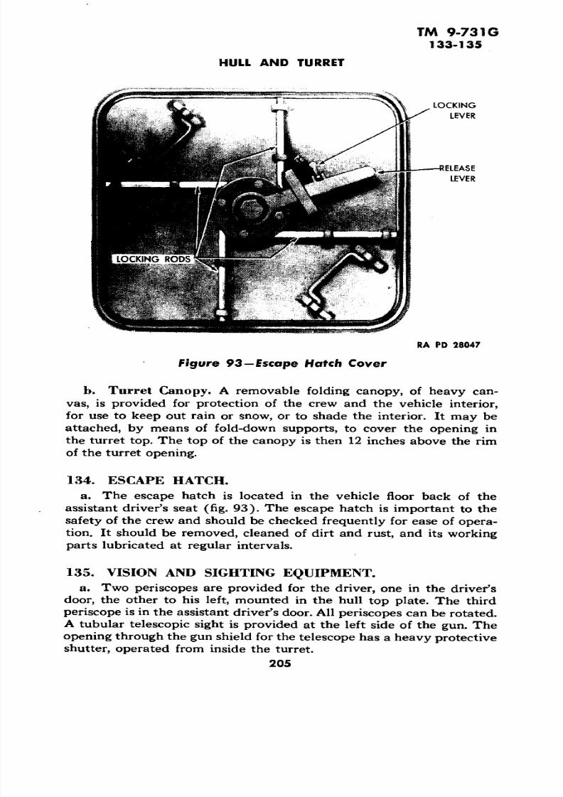
vas, is provided for protection of the crew and the vehicle interior,

for use to keep out rain  or snow, or to shade the  interior.  It may be 

attached, by means  of fold-down supports, to  cover the  opening in 

the turret  top. The top of the canopyis then

12 inches above  the rimof the  turret opening.

a. The escape  hatch  is located  in the  vehicle  floor back of the

assistant driver's seat  (fig. 93). The escape hatch  is important  to the

safety of the crew and should be checked frequently for ease of opera

tion. It should be removed, cleaned of dirt and  rust,  and its working

parts lubricated at regular intervals.

a. Two periscopes are provided  for the driver, one in  the driver'sdoor, the  other to his left, mounted in the  hull top plate. The thirdperiscope is in the assistant driver's door. All periscopes can be rotated.A  tubular telescopic sight is  provided at the left side of  the gun. Theopening through the gun shield for the telescope has a heavy protectiveshutter, operated from inside the turret.

205 

7/29/2019 TM9_731G_1943

http://slidepdf.com/reader/full/tm9731g1943 207/284

TM  9-731G 136-138

3-INCH  GUN MOTOR CARRIAGE M10A1

Section  XXI

FIRE  EXTINGUISHER SYSTEM

Paragraph

Fire extinguisher units .............................. 136Operation  ......................................... 137 Maintenance and replacement. ........................ 138Handling .........................................  139

a. Two sizes of carbon  dioxide fire extinguishers  are carried  ineach vehicle. Two  fixed 10-pound units are clamped  in a vertical position near  the transmission oil cooler on the floor of the fighting compartment (fig. 94). These units connect to tubes leading to the engine compartment and are  used  for extinguishing fires  in the  engine com partment  only .  A 4-pound  portable hand-operated extinguisher is  located  on  a bracket at left of the driver. A second  4-pound portablehand-operated extinguisher is located on  a bracket in   the turret.

a. Operation of  both the  fixed and the portable fire extinguishersis explained in   paragraph 5b(14) (a) and (b). 

138. MAINTENANCE AND REPLACEMENT.

a. After  use,  the extinguisher should immediatelybe exchanged fo r one that is  fully charged. Every 4  months, or oftenerif deemed  necessary, weigh each extinguisher, and if the net weightof the carbon  dioxide 

is lessth

an3Vz

pounds for the 4-pound extinguisher or 9 pounds for the 10-pound  extinguisher, exchange the extinguisher for a  fully charged one.

To  remove the fire  extinguishercylinders, unscrew the control head at the cylinder, loosen the clamps,and remove the cylinders. Recharge with 10 pounds of carbon dioxide,use adapter No. 23848. Reset the control handle. Reset the controlhead by inserting a pin in the  shaft and turning counterclockwiseuntil the clutch pin and the arrow are lined up. Reinstall the cylinder

in vehicle, clamp  in place, and  connect the discharge tube. Assembledischarge head to recharged cylinder.

To remove  the pull cables, disconnectshort conduit running  from  the fire extinguisher cylinder head to  theinlet and outlet connector housing. Cut the cable at connector and pull cable out of  conduit by pulling out handle at front and rear controls. Thread the new  cable  through  conduit and connect cable  (aninstallation drawing is included in the new parts package). To replace 

206

7/29/2019 TM9_731G_1943

http://slidepdf.com/reader/full/tm9731g1943 208/284

TM 9-731G 138

FIRE EXTINGUISHER SYSTEM 

DRIVERS COMPARTMENT

4 LB. PORTABLE   FIRE _ EXTINGUISHER

DR IVERS

CONTROLS

ff •xa— — — — — —r w

TURRET 4 LB .PORTABLE FIRE ———————| — EXTINGUISHER |f Vk

9.1 (1 IB FIXED11\\\\

V"

FIRE EXTINGUISHERS

OUTSIDE CONTROL:

NOZZLES

t ..flf * 

RA PD 27547

Figure 94—Fire Extinguisher System

207

7/29/2019 TM9_731G_1943

http://slidepdf.com/reader/full/tm9731g1943 209/284

TM 9-731G

138-139

3-INCH GUN MOTOR  CARRIAGE  M10A1

conduits, remove cables as outlined and disconnect connectors and

holding brackets. To reinstall, reverse the sequence  of the steps in 

the removal procedure.

To replace fire extinguisher 

nozzles or lines, disconnect connections and holding brackets. Remove

lines and nozzles. To reinstall, reverse  the sequence of the steps in the

removal procedure.

a. Any cylinder containing gas under high pressure is as dangerous

as a  loaded shell. The extinguisher cylinders should never be dropped, 

struck, handled roughly, or exposed to unnecessary  heat.

208

7/29/2019 TM9_731G_1943

http://slidepdf.com/reader/full/tm9731g1943 210/284

TM 9-731G 140-141

PART THREE

ARMAMENT

Section XXII

INTRODUCTION

Paragraph

Scope ............................................ 140Characteristics ..................................... 141Data .............................................. 142

a. This part of the manual is designed to guide the commander and

crew in   the care and handling of the 3-inch Gun  M7 and Mount MS,mounted on Gun Motor Carriage M10A1.

b. In addition to mounting the 3-inch Gun M7 and Mount MS, the

Gun Motor Carriage M10A1 mounts the cal. .50 M2,  heavy barrel,

machine gun; Thompson submachine gun, cal. .45; the cal. .30 rifle,M1903; carbines, cal. .30; grenade, and launcher for cal. .30 rifle. 

c. All essential information that is of a technical character required

by using arms and services for identification, use, and care of the par

ticular equipment described, is contained  in this manual, as well as

use and care of ammunition, spare parts and accessories, and sighting

and fire-control equipment.

d. Disassembly and assembly, and repairs by battery personnel

will be undertaken only under supervision of an officer or chief

mechanic. 

e. In cases where the nature of repair, modification, or adjustment

is beyond the scope and/or facilities of battery personnel, local or

otherwise designated ordnance service should be informed in order

that trained personnel with suitable  tools and equipment may be pro 

vided.

£. All Technical Manuals, Field Manuals, Standard Nomenclature

list, and other publications pertaining to materiel described in this 

manual are listed in "R eferences."

a.  The main armament of the Gun  Motor Carriage M10A1 is a3-inch Gun  M7 that is mounted in a Gun Mount MS. The gun ismounted in a semiopen-top turret of welded armor plate.

b. The 3-inch Gun M7 is used as a tank destroyer. The gun has a

209

7/29/2019 TM9_731G_1943

http://slidepdf.com/reader/full/tm9731g1943 211/284

TM 9-731G 141

3-INCH GUN MOTOR CA RRIAGE M10A1 

CARBINES, CAL. .30 SHELLS, 3-INCH 

RA PD 45690Turret

gun shield that moves  vertically with the barrel and forms the front 

part of the turret. The turret and gun as a  unit are traversed by meansof a handwheel mechanism meshing with a ring gear, thereby enabling 

the gun to be fired in any direction. Two traversing locks are provided

to secure the turret in any desired position.

c. Elevation of the gun is by  means of two elevating handwheels,

one on the right, and the other on left side of cradle. The muzzle of the

gun can be elevated to 30 degrees or depressed to 10  degrees.

d. There are 54 AP and HE shells stored and carried on the vehicle 

(figs. 95 and 96).e. The breech can be automatically or manually opened or closed.

The gun can be electrically or hand fired. Firing mechanism is usually

automatically cocked, but can be hand cocked by means of a hand-

cocking lever.  All rounds are loaded by hand. NOTE: It should be

remembered that the driver and the assistant driver cannot open their

latch  doors while the  3-inch gun is pointed forward, because of interference with the gun shield. However, the gun will normally be carried

210

7/29/2019 TM9_731G_1943

http://slidepdf.com/reader/full/tm9731g1943 212/284

TM 9-731G141-142

INTRODUCTION

CAL. .50 HEAVY BARREL MACHINE GUN M2

TURRET

THOMPSON SUBMACHINE GUN, CAL. .45 SHELLS, 3-INCH"A p

D45697A

f igure 96—Rear Inside View of Turret

with the muzzle to the rear (fig. 97), and both doors may be left open

until the gun is to be directed toward the front.

f. Small arms are covered in the 23 series Field Manuals which are

available to using arms. These weapons will not be included here.

Weight of 3-inch gun (M7) complete. .................. 1,990 IbLength of bore....................................... .50 calLength of tube, muzzle to rear face of breech ring ........ 158.10  in .Caliber .............................................. 3 in .Type of breechblock. ......................... .Vertical-slidingFiring chamber capacity............................ 200 cu in .Density of loading .................................. 0.692Muzzle velocity

...............................2,600 ft per sec

Muzzle energy .................................. 702.9 ft-tonMaximum powder pressure .......................... 36,000 Ib Rifling:

Length ........................................ 126.85 in.Number of grooves.  ....................................28Twist, uniform right-hand with one turn in calibers............ 40

Chamber pressure ...................... 3,200-3,600 Ib per sq in .211

7/29/2019 TM9_731G_1943

http://slidepdf.com/reader/full/tm9731g1943 213/284

TM 9-731G142

3-INCH GUN MOTOR CARRIAGE M10A1

GUN SHIELD BARREL ASSEMBLY GUN REST TURRET

Number of grooves........................................ 28Depth of grooves.................................. 0.04 in .Width of grooves................................... 0.1866 in .Width of lands...................................... 0.15 in .Weight of fixed round................................ 26.66 IbWeight of powder charge................................. 5 IbTravel of projectile  in barrel........................ 127.73 in.3-inch ammunition stored (AP and HE) ................ 54 roundsHE round, M42 B2, weight of projectile................... 12.4 IbAP round, M62, weight of projectile ..................... 15 IbAP round, M79, weight of projectile

.....................15 Ib

Approximate drop of projectile at zero degree ofelevation  ................................ 2,000 to 2,500 yd

Firing switch (in elevating handwheel) . . 15 amperes 24  d-cvolts, normal position,open

212

7/29/2019 TM9_731G_1943

http://slidepdf.com/reader/full/tm9731g1943 214/284

TM  9-731G 142

INTRODUCTION

Firing solenoid ............................ 24 volts, 30 Ib pull

(Maximum air gap at

20  d-c volts)

Elevation of gun................ ................. 30 degreesDepression of gun................................. 10 degreesTraversing ..................................... 360 degreesType of recoil mechanism.........................HydrospringNormal recoil ................................... 11 to 12 in .Maximum recoil ...................................... 14 in .Type of recoil oil used........................ OIL, recoil, heavy

(Spec.2-96A)

Recoil spring compression............................... 12 in .

Recoil spring, number of coils. ..................... 20Va approx.

Recoil spring, length compressed in recoil cylinder. ...... .26.375 in.

Recoil spring, length of free spring. ................... .38.375 in.

Recoil spring tension, gun in battery. ................ 1,058 Ib min

Recoil spring tension, gun in battery. ..............1,136 normal

Recoil spring tension, gun in battery ................ 1,214 Ib max

Elevating handwheel, one revolution produces vertical move

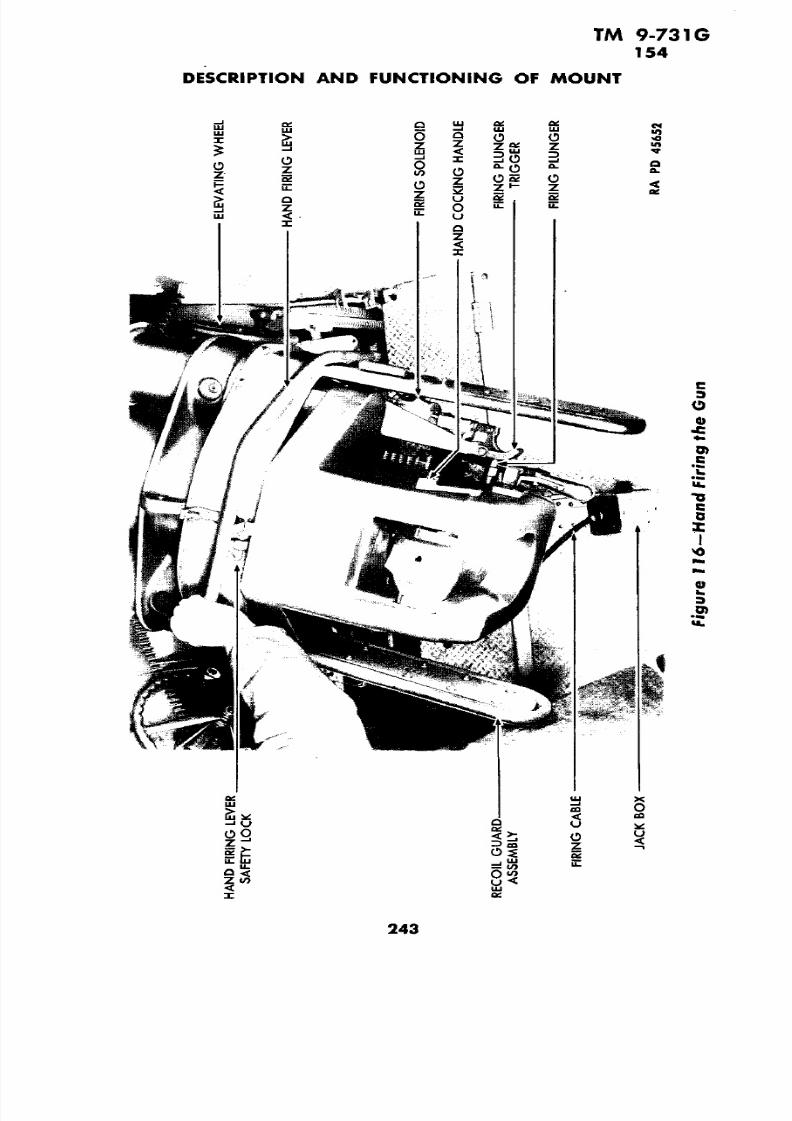
ment of ........................................ 0.0833 in .Elevating handwheel, movement to raise muzzle......... ClockwiseRecoil piston rod pull............................... 10,500 Ib Telescope ............................................ MS 1

213 

7/29/2019 TM9_731G_1943

http://slidepdf.com/reader/full/tm9731g1943 215/284

3-INCH GUN MOTOR CA RRIAGE M10A1

Sect ion XXIII

DESCRIPTION AND FUNCTIONING OF GUN 

Paragraph

General .......................................... 143Barrel assembly .................................... 144Breech mechanism ..................................  145Closing spring m echanism ............................ 146Percussion  and cocking mechan ism... .................. 147Function and operation of breech

mechanism.............148

a. The 3-inch Gun M7 consists of a tube screwed into a breech ring

and  locked by a key.

b. The tube is supported and alined in a cradle that is a part of the

mount assembly. The  rear half of the tube is finish-ground and rides

in  bushings inside of the cradle.

c.Lugs on the sides of the 

breech ring provide the means of attach

ing the two recoil cylinder assemblies which are a part of the gun

mount. Lugs on the bottom of the breech ring are fo r the breechblock

operating shaft and  cranks. The breech closing spring mechanism  is

attached  to a  lug on right side of  breech ring. Interior of breech ring

is machined  so that breechblock can slide upward to close  and down 

ward to open the firing chamber.

d. Gun designation, serial number, name of manufacturer, year of

manufacture, and weight (includes tube, breech ring, and breechblock) 

are stamped on the top of the breech ring.

e. Tube serial number, name of manufacturer, weight of tube with 

breech, and gun  designation  are stamped on the muzzle. The muzzle 

end of  tube is engraved with witness lines for use   with bore-sighting

equipment.

f. Rounds are loaded by  hand, and the action of  loading causes

automatic closing of the breech; however, the breech can be manually

opened (or closed) by use of the breech operating handle which is

secured to  the breech operating shaft.  The gun is fired electrically by means of a solenoid or manually by a  hand-firing  lever. In either case,the act of firing depresses  a firing plunger located on the right cheek

of breech ring. The firing plunger moves the sear, thereby allowing the

firing pin to function. After  firing, the gun recoils and  then counter-

recoils to   battery. During this counterrecoil, the gun is cocked, breech

is  opened, cartridge case   is extracted, and breechblock is locked in   its

open position  (firing chamber open)  ready to receive the next round.

214

7/29/2019 TM9_731G_1943

http://slidepdf.com/reader/full/tm9731g1943 216/284

7/29/2019 TM9_731G_1943

http://slidepdf.com/reader/full/tm9731g1943 217/284

TM 9-731G144

3-INCH GUN MOTOR CARRIAGE M10A1 

_ COCKING LEVER

EXTRACTOR, R.H,

EXTRACTOR, LH.

VERTICAL GROOVE

EXTRACTORTRUNNION

INNER ENDiEAR

BREECHBLOCKBUSHING

BREECHBLOCKBUSHING SCREW

VERTICALGROOVE

VERTICAL LAND RA PD 45664

Figure 98—Breechblock and Extractors—Battery  Position

from the rear corner forward to provide clearance for the cocking lever

arm. The cocking lever is actuated by the cocking lever arm either in 

automatic or manual cocking. Near  the front of the inner walls of the

breech ring are short curved slots (one on each  side) for the purpose

of guiding the outer trunnions of the extractors. Two holes in the rear

face of the breech ring extend forward into the extractor trunnion re

cesses and  house the two extractor plungers and springs. The rear

ends of the two holes are threaded to accommodate the two extractor

plunger plugs. (6) A hole in the right cheek of the breech ring is counterbored and

threaded to receive the firing plunger and firing plunger retainer. Two

tapped holes and a pilot hole near the rear of the right cheek are used

to locate and attach the operating handle stop.

(7 ) Breech operating handle is attached to right end of the breech

operating shaft and  contains the operating handle latch and latch

spring. The function of the breech operating handle is to provide a

manual means of opening or closing the breech.

216

7/29/2019 TM9_731G_1943

http://slidepdf.com/reader/full/tm9731g1943 218/284

TM 9-731G144-145

DESCRIPTION AND FUNCTIONING OF GUN

COCKING LEVER BEVELED FACE

GUIDE RIB

U-SHAPED NOTCH

EYEBOLT

TAPPED HOI

EXTRACTOR

TRUNNION

CHAMBERING GROOVEBEVEL

EXTRACTOR

, LIPS

EXTRACTOR, R.H. EXTRACTOR, L.H.

T-SLOT EXTRACTOR

TRUNNION

OUTER END

RA PD 45660

Figure 99—Breechblock and Extractors—Breech Open

(8) The breech ring provides a housing for the rear end of the tube,the breech mechanism, and the percussion firing mechanism. The rear

ends of the two recoil rods and closing spring mechanism are also at

tached to the breech ring.

The rectangular breech ring key fits in a

keyway in front face of breech ring and also engages a key seat in the

tube.

(1) The breech mechanism consists of a breechblock with percus

sion firing mechanism, breech operating shaft with the breechblock

operating crank, chain terminal crank, and operating crank.

(2) The functions of this breech mechanism are, first, to close the

rear end of the chambers after loading; second, to fire the round of

ammunition after it has been inserted; and finally, to extract the empty

cartridge case from the firing chamber.

217

7/29/2019 TM9_731G_1943

http://slidepdf.com/reader/full/tm9731g1943 219/284

TM 9-731G145

3-INCH GUN MOTOR CARRIAGE  M10A1

COCKING LEVERRECESS  FOR

COCKING LEVER

SHAFT OFCOCKING LEVER

SEAR-

VERTICAL SLOT

FOR ARM OF SEAR

RA PD  45698 

Figure 100—Rear Right Quarter View of Breechblock 

(1) The breechblock is of the vertical sliding type and has a guide

rib on each side which slides in a corresponding groove in each side of

the breech ring recess (figs. 98 and 99).

(2) The top of the breechblock is U-shaped in order to guide the

cartridge into the firing chamber (at rear end of tube). This U-shaped

notch is alined with  the bottom of the U-shaped notch  in the breech

ring so that the cartridge case is cleared when the breechblock is in

its lowered position. The upper front edge of the top of the breech

block  is beveled in order to drive the cartridge into the firing chamberas the breechblock is raised. The rear face of the breechblock, the

guide ribs of the breechblock, the grooves in the breech ring (for the

guide ribs of the breechblock), and the rear wall of the breech ring

recess, are all inclined so that when the breechblock rises, it also moves

forward and thereby completes the seating (chambering) of the

round in the firing chamber  (figs. 98 and 99).

(3) The bottom of the breechblock contains an inclined T-slot in

218

7/29/2019 TM9_731G_1943

http://slidepdf.com/reader/full/tm9731g1943 220/284

TM 9-731G 145

DESCRIPTION AND FUNCTIONING OF GUN

U-SHAPED RECESS FORCOCKING FORK AND

COVER PLATE

COUNTERBORE FOR

RING SPRINGCOCKING FORK RETAINER 

BREECHBLOCK  HOLE FORBUSHING PERCUSSION

MECHANISM

SEAR

GROOVE FOR LUGON FIRING PIN

FIRING SPRING GUIDERETAINER PIN

RA PO 45669

Figure 101 —Rear View of Breechblock

which cross heads of the breechblock operating crank  slide in order to

raise or lower the breechblock assembly (figs. 98 and 99).

(4) In each side of the breechblock is a groove in which the inner

ends of the extractor trunnions of the two extractors slide. The lower

ends of these grooves are parallel to the breechblock guides; however,

the upper ends curve toward the breechblock front face in order to 

impart an accelerated motion to the extractors when extracting and

ejecting a fired cartridge case (figs. 98 and 99).

(5)

There are flats on the vertical lands(on

each side 

ofthe breechblock). These lands provide a surface for corresponding flats

on the inner trunnions of the extractors. The breechblock is  locked in

its open position when the flats of the inner trunnions of the extractors

are on the vertical lands of the breechblock (figs. 98 and 99).

(6) A  hole, which is bored through the center of the breechblock,

houses the percussion firing mechanism (fig. 101). The forward end

of this hole is counterbored and threaded for a breechblock bushing,

which is retained  in the breechblock by a breechblock bushing screw.

219

7/29/2019 TM9_731G_1943

http://slidepdf.com/reader/full/tm9731g1943 221/284

7/29/2019 TM9_731G_1943

http://slidepdf.com/reader/full/tm9731g1943 222/284

TM 9-731G 145

DESCRIPTION AND FUNCTIONING OF GUN

EXTRACTOR EXTRACTOR EXTRACTOR EXTRACTOR

PLUNGER PLUG PLUNGER SPRING PLUNGER PLUNGER PLUG

RA PD 45654

Figure 102—Extractor Plunger, Spring, and Plug

and have a rolling contact with the front wall of the breech ring recess.When the lower ends of the extractors are forced forward by the down

ward or opening movement of the breechblock, the extractor upper

ends and lips are rocked rearward, thereby prying the cartridge case

out of the firing chamber. The rolling contact with the front wall of the

breech ring recess produces an accelerated motion in order to throw

the cartridge case clear of the gun.

(1) Small cylindrical extractor plungers slide in longitudinal holes

that extend from the rear face of the breech ring to extractor trunnionpockets in the side walls of the breech ring recess. Extractor plunger

springs are in the rear ends of these holes. These springs bear rear

ward against extractor plunger plugs that are screwed into the holes.

The extractor plunger plugs press the extractor plunger springs against

the extractor plungers and these plungers press against the outer

trunnions of the extractors.

(2 ) The function of the extractor plungers is to assure the positive

221

7/29/2019 TM9_731G_1943

http://slidepdf.com/reader/full/tm9731g1943 223/284

3-INCH GUN MOTOR  CARRIAGE M10A1

OPERATING CRANK

BREECHBLOCK OPERATING CRANK

BREECH OPERATING HANDLE

SOCKET HEA D SE T SCREW

BREECH OPERATING HA NDL E RETAINING SCREW

CHAIN TERMINAL CR ANK '

locking of the breechblock in its open position. This is accomplished

by the extractor plungers pressing the outer trunnions of the extractors

forward until the flats on inner trunnions are on the flats of the vertical

lands which are on the breechblock.

(fig . 103).

(1) The breech operating shaft provides a means of connecting and

operating the three cranks (operating crank, chain terminal crank, and

breechblock operating crank) in order to cause them  to  rotate as a

unit.

(2)  There is an extra wide spline or land on the breech operating

shaft that mates with a groove of the same width in the hub of each of

the three cranks. The three cranks cannot be  incorrectly installed or

misalined with each other.

(3) The shoulder and hole on the right end of the breech operating

shaft are provided for the attaching of the breech operating handle by

means of a breech operating handle retaining screw and a socket head

setscrew. The left end of the shaft is drilled, radially, to provide a seat

for the operating shaft detent and to house the operating shaft plunger.

The small hole in the end of the shaft is for the plunger retaining screw.

(f ig. 103).

(1) The breechblock operating crank  consists of an internally

splined hub which slides  on the central part of the breech operating

shaft, in between the bottom lugs on the breech ring. The breechblock

222

7/29/2019 TM9_731G_1943

http://slidepdf.com/reader/full/tm9731g1943 224/284

7/29/2019 TM9_731G_1943

http://slidepdf.com/reader/full/tm9731g1943 225/284

7/29/2019 TM9_731G_1943

http://slidepdf.com/reader/full/tm9731g1943 226/284

7/29/2019 TM9_731G_1943

http://slidepdf.com/reader/full/tm9731g1943 227/284

TM  9-731G 147 

3-INCH  GUN  MOTOR  CARRIAGE  M10A1 

Vt•

w

I0)

a. 

0) 

1uI 

«0) 

226 

7/29/2019 TM9_731G_1943

http://slidepdf.com/reader/full/tm9731g1943 228/284

TM  9-731G 147

DESCRIPTION  AND  FUNCTIONING OF GUN 

COCKING LEVER

COCKING FORK PLUNGER COCKING, FORK PLUNGER SPRING 

COCKING FORK

PLUNGER

COVER PLATE  COCKING

FORK

BREECHBLOCK

FIRING SPRING

STOP

< FIRING PIN

GUIDE PIN 

FIRING  PIN

BREECHBLOCK

BU SHING

BREECHBLOCK

BUSHING

SCREW 

FIRING PIN 

SPRING

FIRING SPRING

RETAINER

FIRING SPRING FIRING PIN

RETAINER PIN GUIDE RA PD 45646

Figure 105-Firing  Mechanism  Assembly

227

7/29/2019 TM9_731G_1943

http://slidepdf.com/reader/full/tm9731g1943 229/284

7/29/2019 TM9_731G_1943

http://slidepdf.com/reader/full/tm9731g1943 230/284

7/29/2019 TM9_731G_1943

http://slidepdf.com/reader/full/tm9731g1943 231/284

TM 9-731G 148

3-INCH  GUN  MOTOR  CARRIAGE  M10A1 

230

7/29/2019 TM9_731G_1943

http://slidepdf.com/reader/full/tm9731g1943 232/284

TM 9-731G 148

DESCRIPTION AND FUNCTIONING OF GUN

231

7/29/2019 TM9_731G_1943

http://slidepdf.com/reader/full/tm9731g1943 233/284

TM 9-731G 148

3-INCH GUN MOTOR CARRIAGE M10A1

232

7/29/2019 TM9_731G_1943

http://slidepdf.com/reader/full/tm9731g1943 234/284

TM 9-731G 148

DESCRIPTION AND FUNCTIONING OF GUN

EXTRACTOR. LH. EXTRACTOR, R.H.

BREECHBLOCK BREECH RING

RA PD 45666

Figure 109 —Clos ing the Breech by Loading a Round

operating crank contacts an operating crank ejector cam on the cradle,

and the operating crank is rotated rearward. The operating crank

transmits the rearward motion through the breech  operating shaft to 

the breechblock operating crank, whose arm  swings rearward and

downward, thereby causing the cross heads (on breechblock operating 

crank) to slide in the T-slot of the breechblock and to lower the

breechblock.

(3)  The rotation of the breech operating shaft also rotates the

chain  terminal crank rearward, thereby drawing the closing spring

piston rearward and compressing the closing spring.

(4) As  the breechblock moves downward, the inner trunnions on

the two extractors slide in grooves cut in the sides of the breechblock(figs. 98 and 99). As the cartridge case is uncovered, the forward

curve of the grooves cut in the breechblock forces the inner trunnions

on the extractors forward. The extractors roll on the front face of the

breech recess, and the lips  of the extractors (on upper inner edge)

first engage the rim of the cartridge case, then are  forced  rearward to

draw the cartridge case out of the firing chamber, and eject it from

the breech.

(5) As soon as the breechblock reaches its full open  position, the

233

7/29/2019 TM9_731G_1943

http://slidepdf.com/reader/full/tm9731g1943 235/284

TM 9-731G148

3-INCH GUN MOTOR CARRIA GE M10A1

EXTRACTOR, LH. FIRING CHAMBER EXTRACTOR, R.H.

V

WOODEN BLOCK BREECHBLOCK BREECH RING "A PD 45661

Figure MO—Manually Closing Breech —Wood Block

breechblock is stopped by the  contact of the breechblock operating

crank with a stop surface on the bottom of the breech ring. The ex

tractor plungers now force the outer trunnions  of the two extractors 

forward, forcing the inner trunnion of the extractors to follow the cam

grooves cut  in the sides of the breechblock until the flat surfaces of 

the inner trunnions are seated on  the flat surfaces at the  top of the—

extractor cam grooves  in the breechblock. The breechblock is now 

locked  in  an open position.

(fig. 108).

(1) Unlatch breech operating  handle from operating handle stop

by grasping lever so that operating handle stop latch is lifted clear ofthe stop.

(2) Push breech operating handle

down until a  distinct click canbe heard; then, lift breech operating handle up and  latch  it on the

operating handle stop.

(fig. 109).

(1) Insertion of a round into the firing chamber with sufficient

force to push extractors forward unlocks the breechblock. CAUTION:Do not allow  the fingers or hands to  enter the breech recess. Failureto observe this may result in  injury. Round must be inserted with a

234

7/29/2019 TM9_731G_1943

http://slidepdf.com/reader/full/tm9731g1943 236/284

TM 9-731G 148

DESCRIPTION AND FUNCTIONING  OF  GUN

EXTRACTOR  LH.  FIRING CHAMBER TUBE EXTRACTOR  R.H.

EMPTY  CARTRIDGE  CASE BREECH RING RA PO  71287

Figure  111—Manually Closing  Breech—Cartridge Case

forward and upward movement of the arm using the palm of the handon the base of the round in order to insure that arm  is above  and clear of the breech when  the  breech closes.

(2) As the  round  completes its entry into the firing  chamber,  therim  of  the  cartridge  case strikes the lips of the extractors. The inner trunnions of  the  extractors are forced  off  the flats  of the breechblockand into  the grooves cut in the breechblock, thus releasing the breechblock  from  its  locked position.  The action  of the  compressed  closingspring raises the breechblock to  its closed  or  firing position. 

(3) The closing  spring being  fastened to  the chain  terminal crank causes  the chain  terminal  crank to  turn the breech  operating shaft (crank  being on  the shaft). The  breechblock operating  crank also turns because it is also on  the  breech  operating  shaft. These movingparts  come  to rest when  the  breechblock  cross heads  on  the  breechblock operating crank contact the rear face of the  tube.

(4)  As  the  breechblock  rises,  a  bevel on  the upper  front face of the breechblock drives the  round  into  the  firing chamber. A forwardmovement  is also  imparted  to the round by slightly inclined guides inthe breechblock, and this forward  movement completes the seatingof the  round.

235

7/29/2019 TM9_731G_1943

http://slidepdf.com/reader/full/tm9731g1943 237/284

TM 9-731G148 

3-INCH GUN MOTOR CARRIAGE M10A1

NOTE: Do not use the  fingers to press on extractors as possible

injury  may result.(1) When  it  is desired to close a breech without  inserting a round

in the firing chamber, it can be accomplished with either a wood block

(fig. 110) (about 2 x 4 x 12 in.) or with an empty cartridge case

(fig. HI).

(2) Press on  either one of the two extractors  with a wood block

until the  extractor is pushed forward into its unlocked position; then

press the opposite extractor forward until it is in its unlocked position,

and the breechblock will fly upward.

236

7/29/2019 TM9_731G_1943

http://slidepdf.com/reader/full/tm9731g1943 238/284

TM 9-731G149-150

Section XXIV

DESCRIPTON  AND  FUNCTIONING OF  MOUNT 

Paragraph 

General .......................................... 149Cradle ........................................... 150 Elevating mechanism  ................................ 151Recoil mechanism .................................. 152Gun recoil guard assembly............................ 153Mechanical firing mechanism ......................... 154Electrical firing circuit............................... 155Cam ejector mechan ism .............................. 156

a. The mount assembly  consists of a cradle with elevating mech

anism and two recoil cylinders, mechanical firing mechanism, electrical firing circuit, and operating crank ejector mechanism.

b. The mount assembly rests on trunnions in the turret which ismounted on the Gun Motor Carriages M10 and M10A1.

150. CRADLE (fig. 112).

a. The cradle has  tw o bored sections for  tw o recoil cylinders. Onthe front of these bored sections are  two keys, which  are welded  inplace. These keys fit into keyways in the recoil cylinders in order to

properly locate the recoil cylinders.

b. The gun shield forms the front of the turret. It has the telescope

shutter on the outside with the telescope shutter handle on the inside,thus permitting the shutter to be operated  from inside the turret. A

cylindrical steel section ending in a machined flange is welded to  thecenter of the  inside of the gun shield and the tube passes through this

cylindrical section. The machined flange is separated from the cradle

by a spacer and the gun shield is then bolted through the spacer to the 

cradle.  The gun shield has  two arms which bolt to trunnions located

inside the forward end of the turret (fig. 112).

c. The function of the mount is to provide  stability and alinement

for the gun during recoil and counterrecoil after firing and also  to pro

vide readily accessible means for elevating the gun during firing. 

d. A large centrally bored section in the  cradle contains  bronze

liners and is the barrel support. The finished and ground  section ofthe barrel  slides in the bronze liners during  recoil and counterrecoil.

Lubrication fittings on  the cradle assure lubrication of the ground section of the barrel; and a wiper with retainer keeps excess lubricant and

fo reign matter out of the bronze liners and off the ground section ofthe barrel.

7/29/2019 TM9_731G_1943

http://slidepdf.com/reader/full/tm9731g1943 239/284

3-INCH GUN MOTOR CARRIAGE M10A1

HA PO 71349

Figure 112—Mount Assembly

e. A lug at the top and rear of the cradle is bored to provide a

means of locking the gun in its traveling position. The barrel is toward

the rear, resting in its support, when traveling (fig. 97).

f. The recoil guard assembly is bolted to the rear of the cradle, and

consists of a recoil guard assembly and a hand firing bar assembly. Therecoil guard assembly is composed of a right and left recoil guard

welded together. To these recoil guards is fastened the balancing

weights and one end of the two coil springs used to hold the hand firinglever forward (in neutral position). A swivel-type lock for the hand

firing lever is mounted on top of the recoil guard assembly to lock the

lever in its neutral position. An adjusting screw with stop is bolted tothe top of the recoil guard assembly for the hand firing lever. The hand

firing lever is bolted to the right and left recoil guards and swivels inbrackets bolted to the guards. The function of the recoil guards is to

provide protection for-the gun crew during recoil.

g. The elevating mechanism is bolted to the under side of the

cradle. The mechanical firing mechanism, together with the electrical

firing mechanism, is assembled on the right side of cradle. The oper

ating crank ejector mechanism is mounted on the left side of thecradle.

238

7/29/2019 TM9_731G_1943

http://slidepdf.com/reader/full/tm9731g1943 240/284

TM 9-731G 150-151

DESCRIPTION AND FUNCTIONING OF MOUNT

-ELEVATING SCREW MOUNTING BRACKET ELEVATING WHEEL

. DUST SEAL SWITCH MOUNT. *

LUBRICATION SWITCH WIRE

WHEEL LEVER

: I •

I , P _ ._ SWITCH TO* - SOLENOID WIRE

FIRING CABLE

ELEVATING WHEELRA PD 45649

Figure 113— Elevating Mechanism

h. The telescope mount is attached to a bracket which is welded

on the turret and is connected to the cradle trunnion by means of an

adjustable rod. The telescope is mounted on the cradle at the left sideof the gun and just to the rear of the gun shield. The opening through

the gun shield for the telescope has a heavy protective shutter which

is operated by a handle from inside the turret.

(fig. 113).

(1) The elevating mechanism consists of a centrally located gear to

which is pinned an internally threaded elevating nut that operates anexternally threaded elevating screw. Turning either the right or left

elevating handwheel revolves pinions that mesh with the elevating

gear. The elevating gear is keyed on the elevating nut, and the nut

being threaded internally, operates the externally threaded elevating

screw.(2) The elevating mechanism has the electrical firing wires and

switches attached to it.

239

7/29/2019 TM9_731G_1943

http://slidepdf.com/reader/full/tm9731g1943 241/284

TM  9-731G152-153

3-INCH GUN MOTOR CARRIAGE M10A1

(1) The functions of the recoil mechanisms are to control and limit

the recoil  of the gun caused by firing, to  return the  gun to battery (counterrecoil), and to gradually reduce the  shock of the gun as it

returns finally into battery.

(2) There are two recoil cylinders,  one on each side of the gun.These two recoil cylinders are held and located in the  cradle by two

keys that are welded on the cradle. Two recoil piston rods are screwed 

into the breech ring and then locked to the breech ring by socket head

setscrews that push copper plugs into the threads of the recoil piston

rods. Bothrecoil cylind

ers contain pistons which are  spring operated. The cylinders are kept filled with proper  amount of heavy recoil oil.

(1) The front end of each recoil cylinder has a recoil cylinder purg

ing plug which both retains and locates the recoil cylinder sleeve. The

counterrecoil buffer is located at this end of the sleeve.

(2) The rear end of each recoil cylinder has a nut for holding  therecoil cylinder to the breech ring. The plug  for filling the recoil mech

anism with recoil oil is at this end (fig. 114). 

(1) When in battery position, the recoil cylinder pistons are at the

forward end of the recoil cylinder. Immediately upon firing, the recoil

of the barrel begins and because the recoil cylinder pistons are fastened

to the breech ring, they start backward along with the barrel.

(2 ) The recoil oil in the recoil cylinder is displaced through orifices,and the counterrecoil inner and outer springs are compressed. The re

coil cylinder piston ceases its  travel on recoil, and the compressed

counterrecoil inner and outer springs exert their pressure on the piston,

thereby starting the piston forward on counterrecoil (toward batteryposition).

(1) Counterrecoil buffer mechanism is fastened to the front end ofthe recoil cylinder and is the means of cushioning the last few inches

of counterrecoil just before the barrel reaches battery position.

(2) The counterrecoil buffer fits inside the piston rod, and by dis

placing the recoil oil inside  the piston rod, allows the gun  to return to battery without shock.

(fig. 115) 

(1) The gun  recoil guard assembly consists of an arm on each sideof the breech which extends back  from the cradle  to beyond the end

240

7/29/2019 TM9_731G_1943

http://slidepdf.com/reader/full/tm9731g1943 242/284

TM 9-731G T53

DESCRIPTION AND FUNCTIONING OF MOUNT

o

01

0)ot nc

I)

241

7/29/2019 TM9_731G_1943

http://slidepdf.com/reader/full/tm9731g1943 243/284

TM 9-731G153-154 

3-INCH GUN MOTOR CARRIAGE  Ml OA T

HAND  FIRING LEVER

SAFETY LOCKHAND FIRING LEVER

RA PD 45709

Figure 115 — Gun Recoil Guard Assembly

of the breech ring (fig. 106). The  hand firing lever extends from one

side of the breech  to the other and is bolted to the gun recoil  guard

assembly. The hand firing safety lock is bolted to the top of the gun

recoil guard assembly. Weights to  balance the gun  are  bolted to the

gun recoil guards.

(2) The  function of the  gun recoil guards is to prevent injury to 

the gun crew during recoil and counterrecoil. The hand firing lever

permits the round to be  fired by hand. The hand firing safety lock

secures the hand firing lever in  locked position. The weights to the gun

recoil guards balance the gun assembly to permit easy elevation and

depression. _,

(1) The firing  mechanism consists of a  mechanical firing mech-

that is operated either by the electrical firing circuit or by the

hand firing lever. The function of the  mechanical firing mechanism is

to provide a  means for moving the sear transversely, in order to dis

engage the sear from  the firing pin guide, thereby permitting the firing

pin to strike the cartridge primer.

(2) The mechanical firing  mechanism  consists  of a trigger con-

242

7/29/2019 TM9_731G_1943

http://slidepdf.com/reader/full/tm9731g1943 244/284

TM 9-731G 154

DESCRIPTION AND FUNCTIONING OF MOUNT

c3Oo>

o>c

•oc0

I

V

30>

243

7/29/2019 TM9_731G_1943

http://slidepdf.com/reader/full/tm9731g1943 245/284

TM  9-731G154-156

3-INCH  GUN  MOTOR  CARRIAGE M10A1

nected to a firing  rod and  a hand  firing  lever  that is connected  to  the 

solenoid plunger.

(fig.  116).(1)  A  firing solenoid, mounted on the right side of the cradle, has aspring-operated plunger extending through  the solenoid. The solenoid

plunger  can be operated  electrically  or manually by the hand firinglever, the action  in either  case being to move the solenoid plunger to 

the rear.  The firing plunger trigger is rotated by  the solenoid plungerand pushes  the firing  plunger inward  to move the  sear away from thepercussion mechanism, thereby releasing  the firing pin to fire the

round.

(fig. 116).

(1) The hand firing  lever has a solenoid lever attached  to  its rightend, which contacts the  solenoid  plunger.  When  the  hand  firing lever is pushed forward, the solenoid lever pushes the  solenoid plunger for

ward causing the firing plunger trigger  to  push the firing  plunger in

ward into the breech  ring.  The  lug on the sear (which  has been  hold ing  the  percussion mechanism  in  a cocked position) is moved awayfrom  the percussion mechanism, and the firing pin  is released to fire

the round.(2) The hand firing lever can be locked  in a neutral position by 

means of the hand firing  lever safety lock. The forward movement ofthe hand  firing lever, in  order  to  fully  release  the percussion mech

anism, can be  adjusted by  means of  the  hand  firing lever adjusting screw  (fig . 112).

a. Current for electrically  firing the gun is obtained  by  insertingfiring  cable  into jack box  (fig.  116),  and actual firing of  the  round is 

accomplished by  pressing  the firing  plunger which is in  the knob of 

both elevating wheels.  The pressing of the  firing plunger energizes the firing  solenoid, causing the  same  mechanical action as  described formanual  firing.

b. The  electric wiring necessary^is"'firing  cable, switch  wire, and switch-to-solenoid wire. All wiring  is attached to the  elevating  mechanism  (fig.  113),

(1) The cam  ejector mechanism  consists  of an  ejector cam which is mounted on a  bracket that extends out from left rear end of cradle.

An ejector cam pin holds the cam to  the cradle  and two  ejector  cam screws secure the cam to the cam pin.

244

7/29/2019 TM9_731G_1943

http://slidepdf.com/reader/full/tm9731g1943 246/284

TM 9-731G 156

DESCRIPTION AND  FUNCTIONING OF MOUNT

ELECTRIC ELEVATING

FIRING PLUNGER HANDWHEEL

HANDWHEEL KNOB FIRING CABLERA PD 45675 

Figure 1 17—Electrically Firing the Gun

(2) The inside of the ejector cam has a sloped (cam) surface on

which the breech operating crank  operates. The front end of the ejector cam has an offset lug which contacts a spring-operated retainer

to hold the cam in contact with the breech operating crank.

(fig. 118). The breech operating crank rests

inside of ejector cam when the operating crank and ejector mechanism

are in firing position. The ejector cam spring retainer is maintaining

pressure on the ejector  cam, keeping the cam in contact with the

breech operating crank.

(fig. 118).

(1) The breech operating crank, being attached to the breech oper

ating shaft, recoils and counterrecoils along with the tube and breech.

The ejector cam being attached to the cradle remains stationary dur

ing recoil and counterrecoil.

(2 ) The breech operating crank is carried backward to ride up onto

the ejector cam when recoil starts. The front end of the ejector cam is

forced  inward against the ejector cam spring retainer, and the ejector 

cam  is pivoted outward on the operating crank ejector pin.

245

7/29/2019 TM9_731G_1943

http://slidepdf.com/reader/full/tm9731g1943 247/284

B

R

N

B

O

B

RN

B

O

CO o

f o I

1

3 f TO 

> O

B

O

N

O

N

B

C

M

S

N

O

N

C

C

O

N

EE

O

C

M

EE

O

C

M

C

FRN

PO

TO

R

OLPO

TO

R

PD 4

Figure1—PooCa

d

Ca

Eje

on Op

a

o

7/29/2019 TM9_731G_1943

http://slidepdf.com/reader/full/tm9731g1943 248/284

TM  9-731G 156

DESCRIPTION  AND  FUNCTIONING  OF MOUNT

o t;to

O

a.

ULU 

t CO

Oa. —i

O u 

ce.

LU

O u 

0)

a>a 

JO 

I6)

7/29/2019 TM9_731G_1943

http://slidepdf.com/reader/full/tm9731g1943 249/284

TM  9-731G 156

3-INCH GUN MOTOR CARRIAGE M10A1

(3) As the recoil continues, the breech operating crank continues

its ride up the sloped surface of the ejector cam and off the rear end

of the ejector cam. The ejector cam spring  retainer then pushes theejector cam back into its  normal (straight) position. The recoil con

tinues for a short distance after the breech operating crank  has ridden

off the rear end of the ejector cam.

(fig. 119). Counterrecoil starts with

the breech operating crank off, and to the rear, of the ejector cam. Asthe barrel and breech near the finish of their Counterrecoil, the breech

operating crank strikes the rear end  of the ejector cam. This causes

the breech operating crank to rotate. The  splined breech operatingcrank being on the splined breech operating shaft  rotates  the shaft,

opening the breech and compressing the breech closing spring.

(fig. 119).

(1) The opening of the breech automatically ejects the fired car- -tridge case.

(2) As the  Counterrecoil continues, the breech operating crank

turns off  the end of the ejector cam and onto the  bottom of the cam,

then forward on the bottom of the cam;  and as soon as a  round is in

serted into the firing chamber,  the operating crank and ejector mech

anism are again in firing position.

248 

7/29/2019 TM9_731G_1943

http://slidepdf.com/reader/full/tm9731g1943 250/284

Section XXV

OPERATION OF GUNParagraph

Placing gun in firing position.......................... 157Traversing mechanism ............................... 158Elevating mechanism ............... ............... 159Loading ..........................................  160Firing and precautions during firing. .................... 161Unloading ......................................... 162Placing gun in traveling position....................... 163

a. Remove breech cover, sight covers, and muzzle cover and stow

them in the place assigned for them. Stow  all  equipment not needed

for the operation of the gun.

h. Pull traveling lock pin from  traveling lock; then  swing lock  up

under turret  and install traveling lock pin through lock and turretlock bracket (fig. 120).

c. There are two traversing locks, one on the left side to the rear

TURRET TRAVELING  LOCK TRAVELING LOCK HINGE PIN

TRAVELING LOCK PIN  CRADLE RA PD 4547]

Figure

7/29/2019 TM9_731G_1943

http://slidepdf.com/reader/full/tm9731g1943 251/284

TM 9-731G157-159

3-INCH GUN MOTOR CARRIAGE M10A1

TURRET TRAVERSING WHEEL

TRAVERSING LOCK RECOIL  GUARD GUN ASSEMBLY

RA PD 45663

Figure 121—Traversing Wheel and Lock (Left Side)

of the traversing  wheel (fig. 121), and the other on the right side to

the rear of the panoramic sight (fig. 122). Disengage these traversing

mechanism locks.

d. Install Telescope MS 1  in mount on left side of gun at gun shield.

Open telescope shutter by  turning telescope shutter  handle.

e. Elevate and traverse gun to make certain both mechanisms areworking freely. 

f. Manually open  and inspect breech.

a.  The traversing wheel is located on the left side of the  turret atthe  hull  (fig. 121). Traversing is accomplished  by turning  the trav

ersing wheel either to the right or to the left. Complete traverse of

360  degrees can be obtained.

a. The elevating mechanism  is bolted to the cradle, and two wheels

7/29/2019 TM9_731G_1943

http://slidepdf.com/reader/full/tm9731g1943 252/284

TM 9-731G 159

OPERATION OF GUN

GUN ASSEMBLY TURRET TRAVERSING LOCK RA PD 45665

Figure 122-Traversing Lock, Locked Position {Right  Side;

are provided for elevating the muzzle end of the gun.  One wheel is on

the right side of the gun and the other is on the left. Facing each

wheel, elevation  is accomplished by turning the wheel clockwise, and

depression, by turning the wheel counterclockwise.

b. The electrical firing plunger is located in the center of the knob 

on both elevating wheels. The switch wire, switch-to-solenoid wire,

and firing cable are located on the  elevating mechanism underneath

the cradle.

c. Hand cock the percussion mechanism by pushing down (hard) on hand cocking handle (fig. 124); then fire  the gun  by pressing on 

electrical firing plunger. If a distant click is not heard (caused by therelease of the firing pin), make certain  wire connections are tight.

d. Turn hand firing lever safety lock down (fig. 124)  and repeat

as in c above, by using hand firing lever. If hand firing lever is not to 

be used, turn hand firing lever safety lock up again to avoid accidentalfiring.

7/29/2019 TM9_731G_1943

http://slidepdf.com/reader/full/tm9731g1943 253/284

TM 9-7310159-161

3-INCH GUN MOTOR CA RRIA GE M10A1 

EL EVATING SCREW  ASSEMBLY CRADLE TURRET 

ELEVATING WHEEL  (RIGHT)RA PD 45657

Figure 123-Elevating Wheel (Right)

Manually open the breech by unlatching breech 

operating handle from operating handle stop and pushing handle down

until distinct  click  can  be heard; then lift and latch the handle on

handle stop.

The  round must be inserted  into the firing

chamber with sufficient force to operate the extractors  and  close the

breech.

a. At the command "fire"  the electrical firing plunger (fig. 117)

on the right or the left elevating wheel can  be pushed, or the hand

firing lever pushed to fire  the round (fig. 116).

b.  The  breech is opened and the fired cartridge case is ejected,•automatically, by the action of recoil and counterrecoil. The fired car

tridge case should be immediately removed  from  the  vehicle.

c.  The two recoil cylinders should be kept filled with the properamount of recoil oil. If the gun  returns to battery with shock, it is anindication that the recoil mechanisms  require  recoil oil.

252

7/29/2019 TM9_731G_1943

http://slidepdf.com/reader/full/tm9731g1943 254/284

TM 9-731G 161-162

OPERATION  OF GUN

HAND FIRING  LEVER SAFETY LOCK HAND FIRING LEVER

COCKING LEVER FIR ING CABLE HAND COCKING HANDLE

RA PD  45673

Figure 124—Cocking  with  Hand Cocking Handle

d. The lubrication fitting on the  top of the cradle (fig.  112) is for 

lubricating the tube during its slide on recoil and  counterrecoil. The

tube should be lubricated occasionally during firing.

e. Whenever the  rate of fire permits,  the bore should be  examinedfor  fouling. If present, use bore brush to remove loose particles.

f. When using equipment, make certain that it is placed where it

will not interfere  with the action of gun or crew.

g. Do not stand or sit at the rear of gun  during recoil and ejection.

h. If  enemy shell bursts near weapon, make certain no damage

has been done which might make continued firing dangerous.

a. There are times when  it is necessary to unload the piece. Open

the breech manually and catch the round as it is ejected. When a mis

fire occurs or an extractor breaks, it may  be necessary to use theunloading rammer. NOTE: The rammer will be used to unload a live 

shell only under the commander's supervision and with extremecaution.

253

7/29/2019 TM9_731G_1943

http://slidepdf.com/reader/full/tm9731g1943 255/284

TM 9-731G162-163

3-INCH GUN MOTOR  CARRIAGE  M10A1

TUBE FIRING CHAMBER HAND COCKING HANDLE FIRING SOLENOID 

FIR ING PLUNGER FIRING PLUNGER TRIGGER

RA PD   45651

Figure  125 —Loading the Gun

GUN 

a. Cover the telescope and remove it from its mount, and  place it

in the stowage case. 

b.  Turn traversing  lock handles to the  rear  (figs. 121  and 122);then turn the traversing handwheel until the tube is over the gun rest(fig.  97). Turn  elevating wheel counterclockwise (facing wheel) to

depress tube and seat in gun rest.

CAUTION: Before traveling, inspect and make  certain that bothof the primary  turret traversing locks are fastened.  Visualinspection should be made of carriages equipped with screw type  locksin   order to insure positive engagement of locks. The  position of

the handle will indicate proper engagement on carriages  equippedwith  eccentric  type locks. The traversing mechanism itself acts as anauxiliary  turret brake.  It is not strong enough, however, to lock  theturret securely, particularly when traveling over rough  terrain. Therefore, if of the primary turret traversing  locks are  not securelyengaged when  traveling, the traversing mechanism will break, allowing the gun tube  to swing around and cause serious injury to  the personnel, or  loss of life.

254

7/29/2019 TM9_731G_1943

http://slidepdf.com/reader/full/tm9731g1943 256/284

TM 9-731G 163

OPERATION OF GUN

RECOIL ELEVATING TRAVELING CRADLE RECOIL CYLINDER

CYLINDER SCREW ASSEMBLY LOCK ASSEMBLY

BREECH COVER

Figure

c. Remove traveling lock pin from turret bracket and turn travel

ing lock down. Turn elevating wheel to aline hole in traveling lock

with hole in cradle bracket, and insert traveling lock pin through

traveling lock and cradle bracket (fig. 120).

d. Install breech and muzzle covers.

e. Remove machine gun lock pin from machine gun bracket. Turn

machine gun lock handle up to its unlocked position. Cover cal. .50machine gun; then remove gun and stow inside of turret.

f. Fill two recoil cylinders with the proper amount of recoil oil.

255

7/29/2019 TM9_731G_1943

http://slidepdf.com/reader/full/tm9731g1943 257/284

TM  9-731G164-165

3-INCH  GUN MOTOR  CARRIAGE M10A1

Section  XXVI 

LUBRICATION  OF GUN  AND MOUNT

Paragraph 

Introduction .......................................  164Lubrication guide  ..................................  165Points to be lubricated by ordnance maintenance personnel . 166Special lubrication and service instructions...............  167Reports and  records................................. 168

a. Lubrication  is an  essential part of preventive maintenance,  de 

termining  to a  great extent the  serviceability  of  parts and  assemblies. 

Lubrication instructions  for this materiel are con

solidated in a  lubrication guide  (fig. 127). These specify  the points to

be  lubricated, the periods of lubrication, and  the  lubricant to be used. 

Lubricant •  Interval Interval •  Lubricant

Gun bore {Note 51 OE D  D OE   Gun tube (finished surface)

(Note 2)

Turret  race ring bearings CG   % 

Trunnion bearing 06 MM 0$ Trunnion  bearing 

Cradle liner 06 M CG   Traversing worm and

pinion  shaft bearings 

Traversing worm and 06 % 

pinion shaft bearingsD OE Traversing rack and pinion

Traversing  rack and pinion  OE D[Note 3 I

(Note 3)

M  06 E levating  worm  shaft

housingElevating gear case 06 M 

(Sparingly) 

Breech and  firing mechanism  OE D

(Note  4)

RH Recoil chambers  (fill plugs)(Note 1)

Turret race ring bearings C6 '/<

3-in . GUN

D  OE Breech equalizer chain 

(Clean and oil)

• KEY-

LUBRICANTS INTERVALS

OE— OIL, engine CG—GREASE,  general purpose  D— DAILYSAE 30 (above +12'} No. 1 (above +32°) W—WEEKLY SAE  10  (below +32°) No. 1  or No. 0

(+32° to +10°) M—MONTHLY

OS-GREASE. O.D. No. 0(below +10°) 1/4-500 MILESNo. 0 (above  +32°}No. 00 (below +32°) RH— OIL, recoil, heavy 

RA  PD  70661

Figure  127—Lubricat ion Guide

256

7/29/2019 TM9_731G_1943

http://slidepdf.com/reader/full/tm9731g1943 258/284

TM 9-731G 165-167

LUBRICATION OF GUN AND MOUNT

In addition to the  items on the guide, other small moving parts, such

as hinges and latches, must be lubricated at frequent intervals.

In the field it may not be possible to supply a complete assortment of lubricants called for by the lubrication guide to

meet the recommendations. It will be necessary to make the best use

of those available, subject to inspection by the officer concerned, in

consultation with responsible ordnance personnel.

The following notes apply to the lubrica

tion guide (fig. 127). All note references in the guide itself are  to the

subparagraph below having the corresponding number:

(1)  RECOIL FLUID. Refill with proper quantity and type of recoiloil.

(2) GUN TUBE. Daily and before firing, clean and oil exposed

finished  metal surface. Keep surface covered with thin film of OIL,

engine, seasonal grade.

(3) TRAVERSING RACK AN D PINION. Daily, clean and apply  OIL,engine, seasonal grade.

(4) BREECH  AND  FIRING MECHANISM. Daily and before and after

firing, clean and oil all moving parts and exposed metal surfaces with

OIL, engine, seasonal grade. CAUTION: To insure easy breech oper

ation and to avoid misfiring in   cold weather, clean with SOLVENT,

dry-cleaning, dry and lubricate with  OIL,  lubricating,  for aircraft in

struments and machine guns. To clean firing mechanism, remove and 

operate pin in SOLVENT, dry-cleaning.

(5) GUN  BORE. Daily and after firing, clean and coat with OIL,

engine, seasonal grade.

MAINTENANCE

a. Elevating screw.

b. Two cradle trunnion bearings.

c. Elevating gear case (two places).

d. Telescope mount.

Clean before applying lubricant. Where

bearings can be seen, lubricate armament fittings until new grease isforced from the bearing. CAUTION: Lubricate fittings and oilers after

washing. Never use high-pressure washing system for cleaning artillery

materiel.

The intervals indicated  at points on lubrication

257

7/29/2019 TM9_731G_1943

http://slidepdf.com/reader/full/tm9731g1943 259/284

TM 9-731G167-168

3-INCH  GUN MOTOR CARRIAGE M10A1

guide are for normal service.  For extreme conditions of service, rain,

snow, heat, or dust, reduce intervals on guide by one-third or one-half

or more, if conditions warrant. 

If lubrication instructions are closely  followed,

proper lubricants used, and satisfactory results are not obtained, report

to ordnance personnel.

A complete record of lubrication servicing  will be

kept for the materiel.

258 

7/29/2019 TM9_731G_1943

http://slidepdf.com/reader/full/tm9731g1943 260/284

TM 9-731G 169-170

Section XXVII

SIGHTING EQUIPMENT

Par agraph

General ............ 169

Telescope MS 1 ....... 170 

Periscope M6  ........ . 171

Gunner's quadrant Ml. 172 

a. The sighting equipment for  the 3-inch Gun Motor Carriage M10

consists of the Telescope M51, the Periscope M6, and the Gunner's

Quadrant Ml. Arrangement of the equipment is shown in figure 128.

h. The information  in this chapter is not as complete or as accurate

as will be in a future revision.

a.  The Telescope M51 is  used for direct laying of the gun  against

moving targets when firing the 3-inch Armor Piercing Shell M62.

Observing through the telescope, bring the image of the target to  the

point on the  reticle representing the required range and deflection byrotating the traversing and elevating handwheels of the gun carriage.

RA PD 71349

7/29/2019 TM9_731G_1943

http://slidepdf.com/reader/full/tm9731g1943 261/284

TM 9-731G 170 

3-INCH GUN MOTOR  CARRIAGE M10A1

o0.

0)

260

I

7/29/2019 TM9_731G_1943

http://slidepdf.com/reader/full/tm9731g1943 262/284

TM 9-731G 

170 

SIGHTING  EQUIPMENT 

WINDOW  FRAME  HEAD, ASSEMBLY.

HANDLE 

RA PD 43058

Figure 130— Periscope M6

261 

7/29/2019 TM9_731G_1943

http://slidepdf.com/reader/full/tm9731g1943 263/284

TM 9-731G 170-172

3-INCH GUN MOTOR CARRIAGE M10A1

SCALE

INDEX PLATE

PLUNGER

MICROMETER

AUXILIARY INDEX MARKS

LEVEL

HOLDER

SHOE REFERENCE SURFACE

(0-800 MILS)RA PD 70171

Figure 131 — Gunner's Quadrant Ml

a. The Periscope M6 is used for observation and vision purposes

only. The observer places his hands on the holder of the periscope to

rotate and elevate or depress it until the desired panorama is brought

into the field of view of the instrument.

GUNNER'S

(1) To measure elevation of the gun, place the proper reference

surface (fig. 131) of the gunner's quadrant on the leveling pads of the

gun, parallel to the bore, with the associated arrow pointing in the

direction of fire. Set the "0" of the micrometer opposite its index with

the auxiliary index marks matched.

(2) Disengage the plunger from the notches in the frame, lift the

holder, and lower it slowly until the bubble is seen to pass through its

central position. Allow the plunger to engage the notches, and rotate

the micrometer knob until the bubble is centered with respect to thegraduations on the level vial. Face the side of the quadrant which

bears the arrow in use, and read the elevation indicated on the eleva

tion scale and micrometer; read red or black figures according to the

instructions engraved below the micrometer. Remove the quadrant

from the gurr before firing.

To measure depression angles, proceed

as in a above, with the arrow pointed in the reverse direction.

7/29/2019 TM9_731G_1943

http://slidepdf.com/reader/full/tm9731g1943 264/284

TM  9-731G173-174

Section  XXVIII

AMMUNITION

Paragraph

General .......................................... 173Authorized ammunition .............................  174 Stowage  of ammunition.............................. 175Field reports of  accidents ....... 76

a. Ammunition  for Carriage, motor, 3-in. gun M10, consists of:(1) Rounds for Gun,  3-in., M7.

(2) Cartridges fo r  Gun, machine, cal.  .50 , Browning, M2,  heavy 

barrel. 

(3 ) Cartridges for Gun, submachine, ca l. .45, Thompson, M1928A1.

(4) Cartridges for Rifle, U. S., cal. .30 , M1903 (w/Launcher, grenade, Ml).

(5) Cartridges for Carbine, cal. .30, Ml. (6) Grenades. 

h. Ammunition for Gun, 3-inch, M7, is issued in the form  of  fuzed

complete rounds of fixed ammunition. The term  "fixed" signifies  that

the  propelling charge is not adjustable and  that the round is loaded

into  the cannon as a unit. The  round consists of a primer and propel

ling charge of loose  powder grains contained in   a  cartridge case which

is  crimped rigidly to the fuzed projectile. A complete round includes

all the ammunition components  required  to fire  the weapon once.

a.  The ammunition authorized fo r  use with the weapons mounted 

or carried on this motor carriage, and other ammunition carried on the vehicle, are listed in Table I below. It will  be noted that the nomen

clature (standard  nomenclature) completely  identifies the ammuni

tion as to type and model.

TABLE  I-AUTHORIZED  ROUNDS 

FOR  GUN,  3-IN., M7

SERVICE AMMUNITION 

Projectile,  fixed, A.  P. C,  M62, w/Fuze, B. D., M66A1, and Tracer,3-inch guns,   M1918 (all models), Ml,  M3, M5, M6, and M7.

Projectile, fixed, A. P. C, M62, w/Tracer, 3-inch guns, M1918  (allmodels), Ml, M3, MS, M6, and M7. 

Shot, fixed,  A. P.,  M79, w/Tracer, 3-inch guns, M1918 (all models),

Ml, M3, MS, M6, and M7.

263

7/29/2019 TM9_731G_1943

http://slidepdf.com/reader/full/tm9731g1943 265/284

TM 9-731G 174

3-INCH GUN MOTOR CARRIAGE M10A1

SERVICE AMMUNITION-Cont'd

Shell, fixed, H. E., M42, w/Fuze, P. D., M48, 3-inch (15-pdr.) gun,

M1902MI, and 3-inch guns, M5, M6, and M7. 1

Shell, fixed, H. E., M42A1, w/Fuze, P. D., M48, 3-inch (15-pdr.) gun,

M1902MI, and 3-inch guns, MS, M6, and M7. 1

Shell, fixed, H. E., M42A1, w/Fuze, P. D., M48A1, 3-inch (15-pdr.)

gun, M1902MI, and 3-inch guns, M5, M6, and M7. 2

PRACTICE AMMUNITION

Shot, fixed, T. P., M85, w/Tracer, 3-inch guns, M1918 (all models),

Ml, M3, MS, M6, and M7.

DRILL AMMUNITION

Cartridge, drill, M4A1, w/Fuze, dummy, 21-sec., M42A1, 3-inch guns,

M1918 (all models), Ml, M3, M5, M6, and M7, and 3-inch

(15-pdr.) gun, M1902MI.

Cartridge, drill, MIO, w/Fuze, dummy, 21-sec., M42A1, 3-inch guns,

M1918 (all models), Ml, M3, MS, M6, and M7, and 3-inch (15-pdr.)

gun, M1902MI.

Cartridge, drill, MIS, w/Fuze, dummy, M59, 3-inch guns, M1918

(all models), Ml, M3, M5, M6, and M7, and 3-inch (15-pdr.) gun,

M1902MI.

BLANK AMMUNITION

Ammunition, blank, 3-inch (15-pdr.) gun, M1902MI, and 3-inch guns,

M1918 (all models), Ml, M3, MS, M6, and M7.

AMMUNITION FOR GUN, MACHINE, CAL. .50, BROWNING, M2,

HEAVY BARREL

SERVICE AMMUNITION

Cartridge, armor-piercing, cal. .50, M2. Cartridge, ball, cal. .50, M2. Cartridge, incendiary, cal. .30, Ml. Cartridge, tracer, cal. .50, Ml.

BLANK AMMUNITION

Cartridge, blank, cal. .50, Ml.

DUMMY AMMUNITION

Cartridge, dummy, cal. .50, Ml.

Cartridge, dummy, cal. .50, M2.

AMMUNITION FOR GUN, SUBMACHINE, CAL. .45, THOMPSON, M1928A1

SERVICE AMMUNITION

Cartridge, ball, cal. .45, M1911.

DUMMY AMMUNITION

Cartridge, dummy, cal. .45, M1921.

264

7/29/2019 TM9_731G_1943

http://slidepdf.com/reader/full/tm9731g1943 266/284

TM 9-731G174 

AMMUNITION 

265 

7/29/2019 TM9_731G_1943

http://slidepdf.com/reader/full/tm9731g1943 267/284

TM 9-731G 174

3-INCH GUN  MOTOR CARRIAGE M10A1 

RA PD 61221

Figure  133—Ammunition Stowage—Right Side

AMMUNITION FOR RIFLE,  U. S.,  CAL. .30, Ml 903

(WITH LAUNCHER, GRENADE, Ml)

SERVICE AMMUNITION 

Cartridge, armor-piercing, cal. .30, M2. Cartridge, ball, cal. .30 , Ml. Cartridge, ball, cal. .30 , M2. Cartridge, rifle grenade, cal. .30, M3. 3 Cartridge, tracer, cal. .30, Ml.

266 

7/29/2019 TM9_731G_1943

http://slidepdf.com/reader/full/tm9731g1943 268/284

TM 9-731G 174

AMMUNITION

RA PD 61222

Figure 134 — Ammunition Stowage—Lef t Side

BLANK AMMUNITION

Cartridge, blank, cal. .30, M1909.

DUMMY  AMMUNITION

Cartridge, dummy, cal. .30, M1906 (corrugated).

AMMUNITION FOR CARBINE, CAL. .30, Ml

SERVICE AMMUNITION

Cartridge, carbine, cal. .30, Ml.

Cartridge, grenade, carbine, cal. .30, M6. 4

267

7/29/2019 TM9_731G_1943

http://slidepdf.com/reader/full/tm9731g1943 269/284

TM 9-731G 174-175

3-INCH  GUN MOTOR CARRIAGE M10A1

DUMMY AMMUNITION

Cartridge, carbine, dummy, cal. .30, Ml.

GRENADESSERVICE GRENADES

Grenade, hand, fragmentation, Mk. II, with hand grenade igniting

fuze, M10A2.

Grenade, hand, incendiary, AN-M14, with hand  grenade igniting fuze,M200A1. 5

Grenade, hand, smoke, white, AN-M8, with hand grenade ignitingfuze, M200A1. 5

Grenade, rifle, fragmentation, impact, Ml7. Grenade, AT, M9A1. Grenade, rifle, H. E., M9.

PRACTICE AND TRA INING GRENADES, AND REPLACEABLE PARTS 

Grenade, hand, training, Mk. IA1.Grenade, AT, practice, Mil.Grenade, AT, practice, M11A1.Grenade, AT, practice, M11A2.Fin, assembly, for practice rifle grenade, Mil.Fin, assembly, for AT practice grenade, M11A1.Fin, assembly, for practice rifle grenade, M11A2.Ogive, assembly, for practice rifle grenade, M11A2.Adapter, grenade-projection, Ml."

a. Provision for stowage of the ammunition in the carriage is indi

cated in Table II below and in figures 132 to 134, inclusive. The table

has been prepared to serve as a guide only. It is without reference to

any provision for mounting brackets or stowage boxes, which  may be

occasioned by special conditions in the field, or to ammunition which

may be carried by means of a towed trailer.

268

7/29/2019 TM9_731G_1943

http://slidepdf.com/reader/full/tm9731g1943 270/284

TM 9-731G 175

AMMUNITION

269

7/29/2019 TM9_731G_1943

http://slidepdf.com/reader/full/tm9731g1943 271/284

TM  9-731G 175

3-INCH  GUN MOTOR  CARRIAGE M10A1 

CO

3»• § 

iK

270

7/29/2019 TM9_731G_1943

http://slidepdf.com/reader/full/tm9731g1943 272/284

TM 9-731G175-176

AMMUNITION TABLE II-AMMUNITION STOWAGE

STOWAGE

AMMUNITION  CAPACITY* STOWAGE POSITION

3-inch  rounds— 6 rounds without containers,  in two

3-round brackets on rear turret90 percent armor-piercing10  percent high explosive

54 rounds  wall.48 rounds in  fiber containers in four

sponson compartments.

Caliber .50  300 roundsIn 50-round boxes in brackets under

turret platform.

Caliber  .45 460 rounds440  rounds in 20-round clips in

brackets on right rear turret wall.20 rounds  in clip on  gun.

Caliber .30 rifle 60 rounds In bandoleer  on right front sponson

plate near the assistant driver.

Caliber .30, carbine «* On personnel to whom weapons areassigned.

Hand grenades 12 grenadesIn two boxes  on right turret wall

just  forward  of caliber  .45 ammunition bracket.

Antitank  ( rifle )  grenades  10 grenades  * *

* Excludes provision for ammunition on   towed trailer.**Data not available at time  of  printing.

a. When an accident involving the  use of ammunition occurs dur

ing training practice,  the procedure prescribed  in section VII,  AR

750-10, will be observed by the ordnance officer under whose  super 

vision the ammunition is maintained or issued. Where practicable, re

ports covering  malfunctions of ammunition  in combat will  be made 

to the Chief ofOrdnance, giving the type  of malfunction, type of

ammunition, the lot number of the complete rounds or separate load 

ing components, and condition  under which  fired. 

271 

7/29/2019 TM9_731G_1943

http://slidepdf.com/reader/full/tm9731g1943 273/284

TM 9-731G3-INCH GUN MOTOR CARRIAGE  M10A1

REFERENCES

SNL G-170

Ammunition, blank, for pack, light and medium field

artillery ...:.............................. SNL R-5Ammunition,  fixed and  semifixed, all types, for  pack,

including subcaliber light and medium field artil lery, including complete round data .......'...... SNL R-l

Ammunition instruction material for grenades, pyro technics and aircraft bombs................... SNL S-6

Ammunition, revolver,  automatic pistol, and sub machine gun .............................. SNL T-2Ammunition, rifle, carbine, and automatic gun. ...... SNL T-lPacking materials used by field service  for small armsGrenades,  hand and rifle, and fuzing components.... SNL  S-4

service ammunition' ......................... SNL T-5Service fuzes and primers for" pack, light and medium

field artillery ............................... SNL R-3Carbine, cal. .30, Ml and  M1A1—Parts and equip

ment ................................. SNL B-28Gun, 3-in., M7; and mount, gun, 3-in., M5 SNL C-43 Gun, machine, cal. .50, Browning, M2, heavy barrel, •

fixed and flexible; and ground mounts—-Parts and equipment ................................  SNL A-39

Gun, submachine, cal. .45, Thompson, M1928A1, Ml,Launcher, grenade, Ml and M2—Parts and equip

and M1A1—Parts and equipment  .............  SNL  A-32ment ...................................... SNL B-39

Major items of Group A........................ SNL A-lMajor items of Group B........................ SNL  B-lMajor items of pack, light and medium field artillery;

and armament of these calibers for airplane and combat vehicles ............................ SNL C-l

Rifle, U. S., cal. .30, M1903, M1903A1, and M1903A3—Parts and equipment...................... SNL  B-3

F-69Periscopes, telescopes for periscopes, and direct sight

ing telescopes for use in   tanks................. SNL  F-235Quadrant, gunner's, Ml (mils) .................. SNL F-140Telescope, panoramic, M12. series.  ............... SNL F-214

7/29/2019 TM9_731G_1943

http://slidepdf.com/reader/full/tm9731g1943 274/284

TM 9-7316REFERENCES

Cleaning, preserving and lubricating materials; recoilfluids, special oils, and miscellaneous related items. SNL K-lSoldering, brazing and welding material, gases and re lated items ............................... SNL K-2

Tools, maintenance, for repair of automatic guns, auto matic gun antiaircraft materiel, automatic and semiautomatic cannon and mortars—Individual items

and parts .................................. SNL A-35Tools, maintenance, for repair of pack, light and me

dium field artillery; and armament of these calibers of airplane and combat vehicles. .............. SNL C-18

Current Standard Nomenclature Lists are as tabulated here. An up-to-date list of SNL's is maintained asthe "Ordnance Publications for Supply Index".... OPSI

3-inch Tank Gun Materiel M7 ................... TM 9-323Ammunition, general .......................... TM 9-1900 Ammunition, general .......................... OFSB 3-1Automatic pistol, cal. .45, M1911 and M1911A1. . . . FM 23-35Auxiliary fire-control instruments (field glasses, eye

glasses, telescopes, and watches) .............. TM 9-575Browning machine gun, cal. .50, HB, M2 (mounted in

combat vehicles) .......................... FM 23-65Field artillery and field motor ammunition......... OFSB 3-3Grenades ................................... FM 23-30Instruction guide, small arms data................ TM 9-2200 Ordnance service in the field ................... FM 9-5Qualifications in arms and ammunition training allow

ances ..................................... AR 775-10Range regulations for firing ammunition for training

and target practice ......................... AR 750-10Small arms ammunition ....................... TM 9-1990 Small arms ammunition ....................... OFSB 3-5Targets, target materials, and rifle range construction. TM 9-855 Thompson submachine gun, cal. .45, M1928A1..... FM 23-40U. S. Carbine, cal. .30, Ml...................... FM 23-7U. S. Rifle, cal. .30, M1903 .... FM 23-10Chemical decontamination materials and equipment. TM 3-220 Defense against chemical attack................. FM 21-40Decontamination of armored force vehicles. ....... FM 17-59

273

7/29/2019 TM9_731G_1943

http://slidepdf.com/reader/full/tm9731g1943 275/284

TM 9-731G

3-INCH GUN MOTOR  CARRIAGE M10A1

Radio fundamentals .......................... TM 11-455Radio operator, the........................... TM 11-454Radio set, SCR 610........................... TM 11-615Automotive electricity ......................... TM 10-580 Automotive lubrication  ........................ TM  10-540 Cleaning, preserving, lubricating, and  welding ma

terials and similar items issued by  the Ordnance

Department ............................... TM 9-850Echelon system of maintenance. .................  TM 10-525 Fire prevention, safety precautions, accidents....... TM 10-360Motor transport inspections .................... TM 10-545 Sheet metal work, body, fender and radiator repairs . TM  10-450 Tune-up and adjustment....................... TM 10-530Accessories for Ford  tank engine, model GAA V-8 . TM 9-1731C

Auxiliary generator (Homelite HRUH-28) TM 9-1731K

Ford tank engine, model GAA V-8 ................  TM 9-173 IB

Hull and turret, hull and turret electrical system,tracks and suspension. ...................... TM 9-1750L

Power train (one piece differential) .............. TM 9-1750BCamouflage.Camouflage ................................  FM 5-20Camouflage painting of vehicles and equipment..... FM 5-21

........................ TM 1-455Fuels and carburetion ........................ TM 10-550

1-1

................. TM 10-505

...................... AR 850-15............................. FM 25-10

274

7/29/2019 TM9_731G_1943

http://slidepdf.com/reader/full/tm9731g1943 276/284

7/29/2019 TM9_731G_1943

http://slidepdf.com/reader/full/tm9731g1943 277/284

TM 9-731G

3-INCH GUN MOTOR

B-Cont'd P«ge No.

Breech mechanism—Cont'd

description and functioning—Cont'd firing plunger ............. 224operating crank ........... 223

function and operation. . . . 229-236lubrication ............... 45, 257

Breech operating shaft, descrip tion and functioning. .......... 222

Breech ring, description and func tioning .................. 215-217

Breechblock, description and func tioning .................. 218-220

Breechblock operating crank, de scription and functioning. . . 222—223

Cam ejector mechanism, descrip tion and functioning. ...... 244-248

Carburetor adaptersdescription ................. 116replacement ............ 116-117

Carburetorsdescription ................. 113idler fuel adjustment. ........ 113idler speed adjustment. . . . 113—115removal and installation. ...... 116

Carriage, gun, motor, 3-inch,

M10A1 data ...................... 5-11description ................. 5

Center drive plate travel limit, adjustment .......... 164-165, 170

Chain terminal crank, description and functioning .......... 223-224

Characteristics of armament. 209-211Circuit breakers

description ................. 145operation ................... 12 replacement ......... 139,145-148

Cleaningfuel filter ................... 121 oil filter .................... 102

Closing spring mechanismconstruction ............ 224-225function .................... 225

Clutchclutch drag ............. 163-165description ................. 16 3during-operation service ...... 34replacement ............ 166-170

Clutch pedal, description. ....... 21Clutch pilot bearing, lubrication. . 44

CARRIAGE M10A1

Page No.

Clutch pressure plate, installation. 168Compartment light, description. . . 156Conduits and wires

description and maintenance. . . 157 replacement ............ 157—158

Controlled differential and sub-assembly, maintenance duties by echelons .................. 56

Cooling systemaccessory drives ......... 129-130antifreeze .................. 124corrosion inhibiter ........... 125description and maintenance. . . 124 draining ................... 93expansion tank and filler. ..... 13 1fans ................... 128-129filling ...................... 98maintenance duties by echelons 55 radiator ................ 125-127thermostat .................. 130water pump ............. 127-128

Corrosion inhibiter, description. . . 125Cradle, description and functioning .............. 237-239

Crankcase, lubrication .......... 43Crankcase breather

description ................. 102servicing filter element. ....... 103

Current limitator, description. . . . 140Cylinder heads and gaskets, second

echelon preventive maintenance services ..................... 70

Dataarmament .............. 211-213carriage ................... 5—11engine .'.................. 82—84

Dead track blockdefinition ................... 197installation ................. 199removal ................ 197-198

Decontaminator, second echelon preventive services ........... 76

Degassers, description and replacement ................. 116

Description (See Descriptionand functioning)

accessory drives ............. 129air cleaners ................. 117ammeter ................... 148battery .................... 140

276

7/29/2019 TM9_731G_1943

http://slidepdf.com/reader/full/tm9731g1943 278/284

7/29/2019 TM9_731G_1943

http://slidepdf.com/reader/full/tm9731g1943 279/284

7/29/2019 TM9_731G_1943

http://slidepdf.com/reader/full/tm9731g1943 280/284

7/29/2019 TM9_731G_1943

http://slidepdf.com/reader/full/tm9731g1943 281/284

7/29/2019 TM9_731G_1943

http://slidepdf.com/reader/full/tm9731g1943 282/284

7/29/2019 TM9_731G_1943

http://slidepdf.com/reader/full/tm9731g1943 283/284

7/29/2019 TM9_731G_1943

http://slidepdf.com/reader/full/tm9731g1943 284/284

TM 9-731GINDEX 

T-Con t 'd   Page No . U Page No.