The TMC389 evaluation board features a TMC389 with external power MOSFETs plus a microcontroller, which allows interfacing to a PC for visualization and control of all parameters. The motor can be operated via the step and direction interface, using either an external source, or using the integrated microcontroller as a step pulse generator. Highlights
Evaluate all features of the TMC389
Use stallGuard2™ with your motor
Use coolStep™ with your motor
Control all parameters from a PC
Motor current can be set to up 6A depending on sense resistor selection.
Supply voltage up to 40V (MOSFETs can be exchanged against 60V 2A types)
Access all pins of the TMC389
Motor type
3 phase Stepper
TMC389-EVAL manual Evaluation board for the TMC389 three phase
1 FEATURES .......................................................................................................................................... 1
2 TABLE OF CONTENTS ........................................................................................................................ 2
3 GENERAL DESCRIPTION .................................................................................................................... 3
3.1 POWER DRIVER STAGE ...................................................................................................................... 3 3.2 SENSE RESISTORS AND CURRENT SETTING .............................................................................................. 4 3.3 POWER SUPPLY FILTER CAPACITORS ..................................................................................................... 4 3.4 OPTIONAL COMPONENTS ................................................................................................................... 4
5.1 OPERATIONAL RANGE ....................................................................................................................... 8
6 GETTING STARTED ............................................................................................................................ 9
6.1 FIRST STEPS ................................................................................................................................... 9 6.1.1 Connecting to the board .................................................................................................... 9 6.1.2 Current setting .................................................................................................................... 9 6.1.3 Starting the motor .............................................................................................................. 9 6.1.4 Clock frequency setting .................................................................................................... 10 6.1.5 Using stallGuard2™ and coolStep™ ................................................................................ 10 6.1.6 Optimizing the chopper settings ...................................................................................... 11
6.2 MORE SCREEN SHOTS ..................................................................................................................... 12 6.3 WRITING THE SETTINGS TO A .C FILE ................................................................................................. 12
7 REVISION HISTORY ........................................................................................................................ 14
figure 1: application block diagram as realized on TMC389-EVAL
The TMC389-EVAL board features the TMC389 plus a microcontroller, which realizes an interface to a PC.
3.1 Power driver stage The power MOSFETs on resistance mainly influences the current and voltage capability of the board. Therefore, a choice of different MOSFETs can be soldered to the board. Component selection:
The TMC389 driver has powerful 40V MOSFETs FDD8424H for motor currents up to 6A peak. With these MOSFETs, the supply voltage is limited to 40V.
The MOSFETs can be exchanged against complementary N&P channel SO8 types, e.g. 60V type SI4559ADY (SO8). These will allow a motor current of max. 3A peak.
Small 60V MOSFETs SI3458BDV and SI3459BDV are also possible for up to 2A peak.
3.2 Sense resistors and current setting There is one foot point sense resistor on the board which is realized using two resistors (R15 and R16). The second resistor can be paralleled using a soldering jumper in order to lower the effective value and to increase current. As a default, a 150mΩ 2510 type resistor is used. The second 150mΩ resistor can be switched in parallel to double the motor current. For different current requirements, the sense resistors can be exchanged (see table). The sense resistors should be chosen in a way, that they fit the maximum required motor current. The current can be scaled down in the TMC389, but scaling down the current too much reduces effective microstep resolution. There also is a half current setting available (VSENSE=1), which does not affect the microstep resolution. Its main purpose is to halve the sense resistor power dissipation. At current settings above 5A, take care not to exceed maximum MOSFET power stage temperature, as the MOSFET power dissipation increases with the square of the current. On the evaluation board, the distance between MOSFETs and TMC389 is quite large, so the TMC389 does not directly see MOSFET heating and will not be able to protect the MOSFETs against overtemperature. Motor current limit at full current setting via Step/Direction interface (example values):
Sense resistor value
RSENSE
Current (peak)
ICOIL
Current RMS
ICOILRMS
Current (peak)
ICOIL
Current RMS
ICOILRMS
VSENSE=0, CS=28 VSENSE=1, CS=28
330mΩ 0.44 0.31 0.81 0.57
330mΩ || 330mΩ 0.88 0.62 1.62 1.15
220mΩ 0.66 0.47 1.22 0.86
220mΩ || 220mΩ 1.32 0.93 2.43 1.72
150mΩ 0.97 0.68 1.79 1.26
150mΩ || 150mΩ 1.93 1.37 3.57 2.52
100mΩ 1.45 1.02 2.68 1.89
100mΩ || 100mΩ 2.9 2.05 5.36 3.79
75mΩ || 75mΩ 4.46 3.15 8.24 5.83
In a practical application, especially with low ohmic sense resistors, trace resistance can significantly influence the reachable current. Care has to be taken to realize a compact layout with low GND resistance in order to reach a good microstep performance. Component selection: It is important to use low inductivity resistors like Vishay WSL2512.
3.3 Power supply filter capacitors As a chopper operated motor driver draws current in short intervals, it causes noise on the power supply. Therefore it is important to filter the power supply using a capacitor, in order to reduce electromagnetic emission (EME) via power supply cables. Further, the capacitor should be able to store energy fed back from the motor, when the motor becomes decelerated. This depends on the application velocity and mechanics. Component selection: Due to the high frequent ripple, low ESR capacitors are required for this application. The evaluation board uses Vishay 150RMI series capacitors. These provide a very long life time even at high environment temperatures. The required total capacity depends on desired motor current and on the distance to the power supply.
3.4 Optional components There are optional filter components designed in on the board. These allow experimenting with EME filters, e.g. RC and LC filter with RC dampening. Please see the board schematic for sample values.
VS 2 9V-40V Supply voltage. Provide sufficient current capability for driving the motor.
4.1.2 Stepper motor connector K13 (or K10)
Pin Number Level Description
A1 1 VS Motor coil U
A2 2 VS Motor coil V
A3 3 VS Motor coil W
Attention: Do not pull or plug the motor connector during operation, as inductive spikes could destroy the driver. First disable the driver (there is a button in the Eval software) or switch off the power supply.
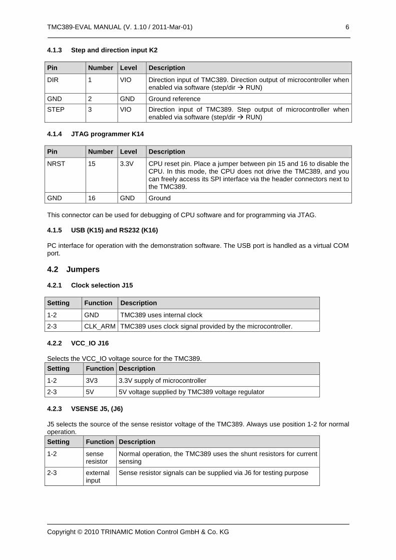
DIR 1 VIO Direction input of TMC389. Direction output of microcontroller when enabled via software (step/dir RUN)
GND 2 GND Ground reference
STEP 3 VIO Direction input of TMC389. Step output of microcontroller when enabled via software (step/dir RUN)
4.1.4 JTAG programmer K14
Pin Number Level Description
NRST 15 3.3V CPU reset pin. Place a jumper between pin 15 and 16 to disable the CPU. In this mode, the CPU does not drive the TMC389, and you can freely access its SPI interface via the header connectors next to the TMC389.
GND 16 GND Ground
This connector can be used for debugging of CPU software and for programming via JTAG. 4.1.5 USB (K15) and RS232 (K16) PC interface for operation with the demonstration software. The USB port is handled as a virtual COM port.
4.2 Jumpers 4.2.1 Clock selection J15
Setting Function Description
1-2 GND TMC389 uses internal clock
2-3 CLK_ARM TMC389 uses clock signal provided by the microcontroller.
4.2.2 VCC_IO J16 Selects the VCC_IO voltage source for the TMC389.
Setting Function Description
1-2 3V3 3.3V supply of microcontroller
2-3 5V 5V voltage supplied by TMC389 voltage regulator
4.2.3 VSENSE J5, (J6) J5 selects the source of the sense resistor voltage of the TMC389. Always use position 1-2 for normal operation.
Setting Function Description
1-2 sense resistor
Normal operation, the TMC389 uses the shunt resistors for current sensing
2-3 external input
Sense resistor signals can be supplied via J6 for testing purpose
Connect a stepper motor to the board, connect the PC via RS232 or USB and use a laboratory power supply to power the board with for example 24V. Now, copy the software to your PC and install USB driver, if necessary.
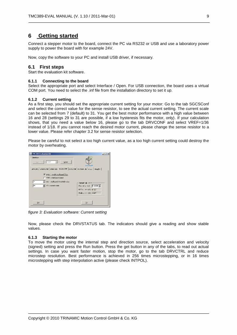
6.1 First steps Start the evaluation kit software. 6.1.1 Connecting to the board Select the appropriate port and select Interface / Open. For USB connection, the board uses a virtual COM port. You need to select the .inf file from the installation directory to set it up. 6.1.2 Current setting As a first step, you should set the appropriate current setting for your motor: Go to the tab SGCSConf and select the correct value for the sense resistor, to see the actual current setting. The current scale can be selected from 7 (default) to 31. You get the best motor performance with a high value between 16 and 28 (settings 29 to 31 are possible, if a low hysteresis fits the motor, only). If your calculation shows, that you need a value below 16, please go to the tab DRVCONF and select VREF=1/36 instead of 1/18. If you cannot reach the desired motor current, please change the sense resistor to a lower value. Please refer chapter 3.2 for sense resistor selection. Please be careful to not select a too high current value, as a too high current setting could destroy the motor by overheating.
figure 3: Evaluation software: Current setting
Now, please check the DRVSTATUS tab. The indicators should give a reading and show stable values. 6.1.3 Starting the motor To move the motor using the internal step and direction source, select acceleration and velocity (signed) setting and press the Run button. Press the get button in any of the tabs, to read out actual settings. In case you want faster motion, stop the motor, go to the tab DRVCTRL and reduce microstep resolution. Best performance is achieved in 256 times microstepping, or in 16 times microstepping with step interpolation active (please check INTPOL).
6.1.4 Clock frequency setting You can modify the TMC262 clock frequency delivered from the CPU to the TMC262. As also the SPI and Step signal input synchronization are affected by this setting, we advise working with 16MHz or with the internal clock frequency (Jumper setting for internal or external CLK should be done before board power up). Default is 16MHz. 6.1.5 Using stallGuard2™ and coolStep™ In order to use the stallGuard2™ functionality and coolStep™, you should first tune the stallGuard2™ sensitivity. As a first step, you should enable the stallGuard™ filter bit SFILT in the tab SGCSCONF.
figure 6: Evaluation software: coolStep setting
Therefore, operate the motor at a reasonable velocity (taking into account your application) and look at the stallGuard™ value (SG) in the DRVSTATUS tab or watch the stallGuard value in the Graph tab. Now, apply slowly increasing mechanical load to the motor. If the motor stalls before the stallGuard™ value reaches zero, go to the SGSCONF tab and decrease the stallGuard threshold value (SGT). A good starting value is zero. You can apply negative values and positive values. If the values leave a
range outside +/-10, probably your velocity setting is too high or too low. If the SG value reaches zero far before the motor stalls, increase the SGT value. The optimum setting is reached, when the stallGuard2™ value reaches zero at increasing load shortly before the motor stalls due to overload. Now, you are ready to enable coolStep™! Go to the SMARTEN tab and set SEMAX and SEMIN to a value different from 0. This enables coolStep. A good value for both is 1 or 2 for most motors. Now, coolStep is enabled and you should see the current scale SE decreasing when the motor does not see any load (see tab Graph). You can modify current increase and current reduction speed by changing SEUP and SEDN. You can select, if the current becomes scaled down to ½ of CS or to ¼ of CS, using SEIMIN setting. For details and sample traces, please see the TMC389 data sheet. Hint: For first tests, we recommend setting SEIMIN to ½, as the ¼ setting might not work stable with increasing load without adapting the SGT value to the actual motor current. 6.1.6 Optimizing the chopper settings In principle, you can run the motor with default settings, but you might want to try improving or modifying the chopper setting for smoothest performance of the motor and for low chopper noise. Start the motor at the desired velocity, e.g. a medium velocity to tune const toff mode fast decay time, or a low velocity to tune chopper hysteresis setting or sine wave offset in const toff mode. Go to the tab CHOPCONF. There is no need to modify the blank time, unless you change the MOSFETs on the board. For most motors, you can work without chopper off time (NOSD box checked). You can check motor microstep behavior and chopper noise (should not come into the audible range) for different HYST settings to improve motor behavior. Chopper synchronization (CSYNC) will improve behavior at higher motor velocity.
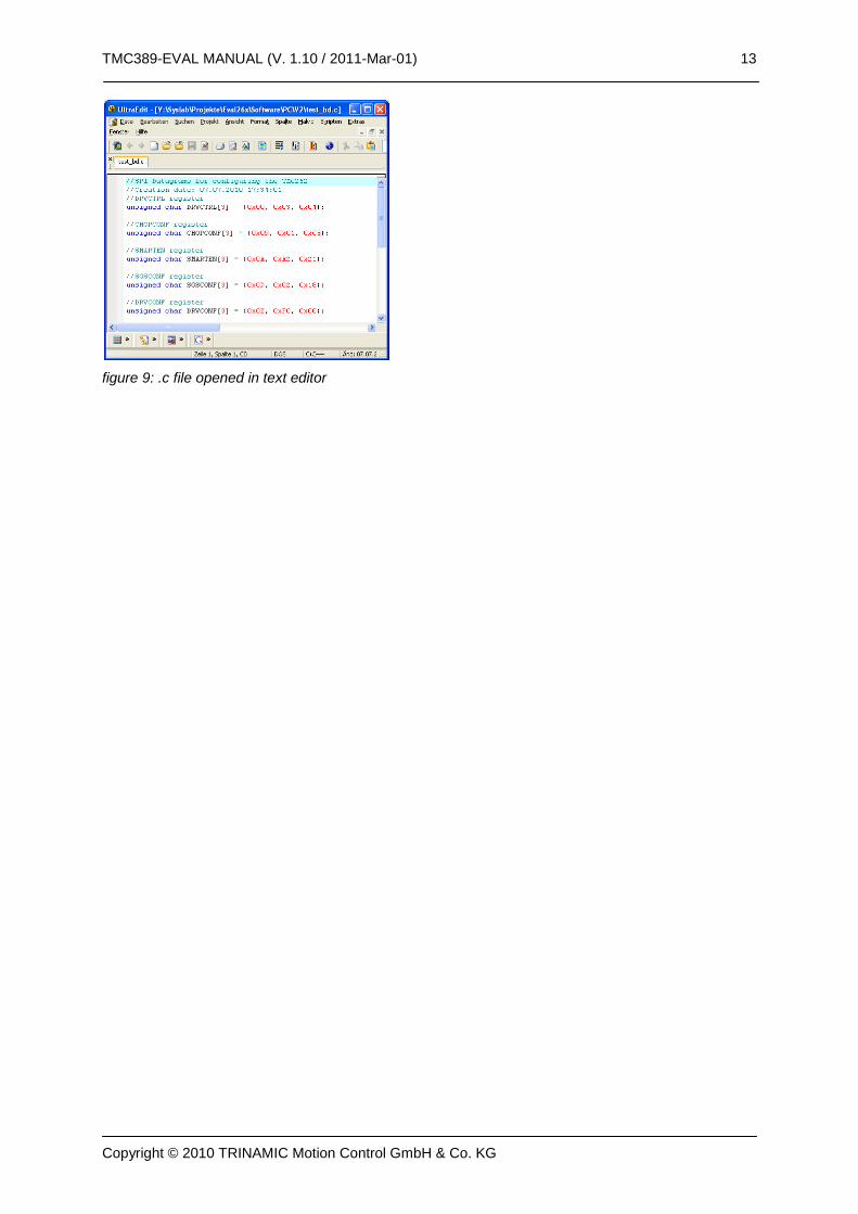
6.3 Writing the settings to a .C file You can load and store all settings made in the evaluation board. They are stored in a .389 text file, which is user readable.
figure 8: .389 or .262 file opened in text editor
In order to transfer the settings into your own software, there is a C language export function. This will write out the initialization values for the TMC262 in a C syntax form, which allows easy sending via a microcontroller SPI interface.