Table of Contents 1 Life support policy ....................................................................................................................................................... 4 2 Features........................................................................................................................................................................... 5 3 Order codes .................................................................................................................................................................... 6 4 Electrical and mechanical interfacing ..................................................................................................................... 7
4.1 Dimensions ........................................................................................................................................................... 7 4.2 Connecting the module .................................................................................................................................... 8
4.2.1 Power supply ............................................................................................................................................. 8 4.2.2 Motor and STOP / reference switches ................................................................................................ 9 4.2.3 Interfaces RS-232 and CAN .................................................................................................................... 9 4.2.4 SPI / programmer ................................................................................................................................... 10 4.2.5 Additional inputs and outputs ........................................................................................................... 10
6.2 Power supply ..................................................................................................................................................... 13 6.2.1 Communication interface ..................................................................................................................... 13
6.4 Reference switches ........................................................................................................................................... 16 6.4.1 Left and right limit switches .............................................................................................................. 16 6.4.2 Triple switch configuration ................................................................................................................. 17 6.4.3 One reference switch ............................................................................................................................ 17
6.5 Additional inputs and outputs ...................................................................................................................... 17 6.6 Microstep resolution ........................................................................................................................................ 18 6.7 Jumpers, other connectors and LEDs .......................................................................................................... 18
6.7.1 Blank time ................................................................................................................................................ 18 6.7.2 Programmer connector and jumper J101 (rev. 1.1) ...................................................................... 18 6.7.3 Programmer connector (rev. 2.0) ....................................................................................................... 19 6.7.4 SPI jumpers .............................................................................................................................................. 19 6.7.5 Shutdown jumper .................................................................................................................................. 19 6.7.6 Reset button ............................................................................................................................................ 19 6.7.7 Power LED ................................................................................................................................................ 19 6.7.8 Activity LED .............................................................................................................................................. 19
7 Putting the TMCM-310 into operation .................................................................................................................. 20 8 TMCM-310 operational description ........................................................................................................................ 21
8.1 Calculation: velocity and acceleration vs. microstep- and fullstep frequency ................................ 21 9 TMCL ............................................................................................................................................................................... 23 10 Differences between hardware rev. 1.1 and 2.0 ............................................................................................... 24 11 Revision history .......................................................................................................................................................... 25
2 Features The TMCM-310 is a triple axis 2-phase stepper motor controller and driver module. It provides a complete single board motion control solution at low cost. Using the integrated additional I/Os it even can do complete system control applications. The motors and switches can be connected easily with screw terminals. The connection of the multi purpose I/Os can be done via a dual-in-line pin connector. The TMCM-310 comes with the PC based software developer environment TMCL-IDE for the TRINAMIC Motion Control Language (TMCL). Using predefined TMCL high level commands like “move to position” or “constant rotation” rapid and fast development of motion control applications guaranteed. The TMCM-301 can be controlled via the RS-232 or the CAN interface. Communication traffic is very low since all time critical operations, e.g. ramp calculation are performed on board. A user TMCL program can be stored in the onboard EEPROM for stand-alone operation. The firmware of the module can be updated via the serial interface. With the optional StallGuard™ feature it is possible to detect overload and stall of the motor. Applications
Controller / driver board for control of up to 3 Axis
Versatile possibilities of applications in stand alone or pc controlled mode Motor type
Coil current from 300mA to 1.1A RMS (1.5A peak)
8V to 34V nominal supply voltage Highlights
Automatic ramp generation in hardware
StallGuardTM option for sensorless motor stall detection
Full step frequencies up to 20kHz
Fully protected drive
On the fly alteration of motion parameters (e.g. position, velocity, acceleration)
Local reference move using sensorless StallGuard™ feature or reference switch
Coil current adjustable by software
Up to 16 times microstepping
Many adjustment possibilities make this module the solution for a great field of demands Software
Stand-alone operation using TMCL or remote controlled operation
TMCL program storage: 16 KByte EEPROM (2048 TMCL commands)
PC-based application development software TMCL-IDE included Other
4.1 Dimensions Maximum height: 25mm. Be aware, that the additional in- and output connector as well as the optional CAN connector is upright. The dimensions in Figure 4.1 are the same for rev. 1.x and 2.0.
4.2 Connecting the module Figure 4.2 gives an overview of the module and helps to locate all important parts. It also shows how to connect the stepper motors and reference switches (if needed).
+Vs=12..28V DC
Reset button
Motor 0 Motor 1 Motor 2
Additional Inputs and Outputs (X300)
TMC236or
TMC246
TMC236or
TMC246
TMC236or
TMC246
TMC428ATmega
32
RS23
2
Pin 1
Blank1 (J400)
Blank2 (J401)
Pin 1
SPI jumpers (J200) (always closed,rev. 1.0 only)
J101
J100
Programmer / SPI
Pin 1
CAN bus (optional
)
CAN Termination(J500)
+Vs
GND
for Hardwarerev. 2.0:
X102
J100, J101: rev 1.0 only
X102: rev 2.0 only
+VSGND
STOP 0
rev. 2
.0
STOP 1
rev. 2
.0
STOP 2
rev. 2
.0
M M M
4 3 2 1 3 2 14 4 3 2 1 3 2 14
GND
4 3 2 1 3 2 14
B1 B0 A1 A0 L R
+5v B1 B0 A1 A0
GND L R
+5v B1 B0 A1 A0
GND L R
+5v
Figure 4.2: TMCM-310 overview
4.2.1 Power supply The power supply can either be connected to the X504 / X505 "Trinamic Standard" 5.08mm power plug or to the power socket X503 (industry standard power socket with 2.0mm pin diameter). Both connections are electrically identical.
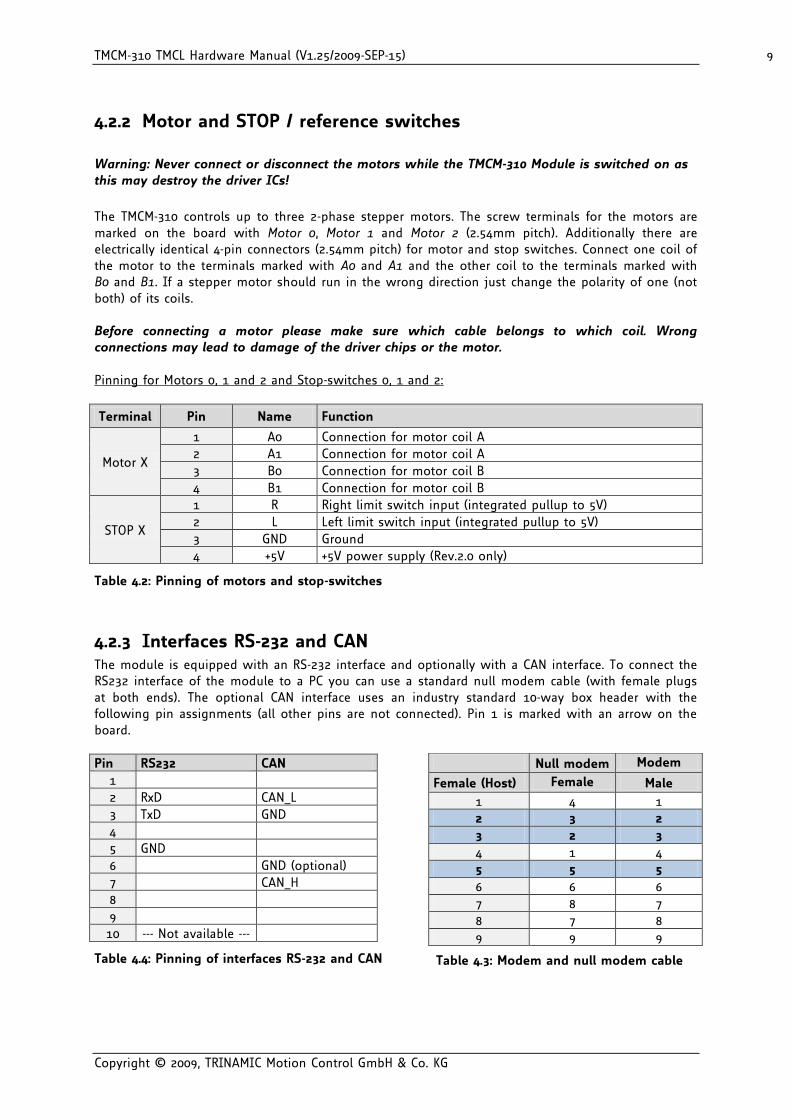
Warning: Never connect or disconnect the motors while the TMCM-310 Module is switched on as this may destroy the driver ICs!
The TMCM-310 controls up to three 2-phase stepper motors. The screw terminals for the motors are marked on the board with Motor 0, Motor 1 and Motor 2 (2.54mm pitch). Additionally there are electrically identical 4-pin connectors (2.54mm pitch) for motor and stop switches. Connect one coil of the motor to the terminals marked with A0 and A1 and the other coil to the terminals marked with B0 and B1. If a stepper motor should run in the wrong direction just change the polarity of one (not both) of its coils. Before connecting a motor please make sure which cable belongs to which coil. Wrong connections may lead to damage of the driver chips or the motor. Pinning for Motors 0, 1 and 2 and Stop-switches 0, 1 and 2:
Terminal Pin Name Function
Motor X
1 A0 Connection for motor coil A
2 A1 Connection for motor coil A
3 B0 Connection for motor coil B
4 B1 Connection for motor coil B
STOP X
1 R Right limit switch input (integrated pullup to 5V)
2 L Left limit switch input (integrated pullup to 5V)
3 GND Ground
4 +5V +5V power supply (Rev.2.0 only)
Table 4.2: Pinning of motors and stop-switches
4.2.3 Interfaces RS-232 and CAN The module is equipped with an RS-232 interface and optionally with a CAN interface. To connect the RS232 interface of the module to a PC you can use a standard null modem cable (with female plugs at both ends). The optional CAN interface uses an industry standard 10-way box header with the following pin assignments (all other pins are not connected). Pin 1 is marked with an arrow on the board.
4.2.4 SPI / programmer Either for reprogramming the CPU or for attaching other external devices with SPI interface. See 6.7.2 and 6.7.3 for further information.
Pin Number Function
MISO 1 SPI master in slave out (pin 1 marked on board)
+5V 2 +5V
SCK 3 SPI serial clock
MOSI 4 SPI serial output (master out slave in)
nSCS 5 SPI low active device select
GND 6 GND (0V)
Table 4.5: SPI / programmer pinning
4.2.5 Additional inputs and outputs An industry standard 20-way (2x10, 2.54mm pitch) box header is used. Pin 1 is marked by an arrow on the board. The row near the edge of the board contains the pins with odd numbers and the other row contains the pins with even numbers.
5 Operational ratings The operational ratings show the intended / the characteristic range for the values and should be used as design values. In no case shall the maximum values be exceeded.
Symbol Parameter Min Typ Max Unit
VS (V1.x) DC Power supply voltage for operation 9 12… 28 28 V
VS (V2.0) DC Power supply voltage for operation 8 12… 28 34 V
ICOIL Motor coil current for sine wave peak (chopper regulated, adjustable via software)
0 0.3… 1.5 1.5 A
fCHOP Motor chopper frequency 25 kHz
IS Power supply current (per motor) << ICOIL 1.4 * ICOIL A
U+5V +5V output (max. 150mA load) 4.8 5.0 5.2 V
VINPROT Input voltage for StopL, StopR, GPI0 (internal protection diodes)
-0.5 0… 5 V+5V+0.5 V
VANA INx analog measurement range 0… 5 V
VINLO INx, StopL, StopR low level input 0 0.9 V
VINHI INx, StopL, StopR high level input (integrated 10k pullup to +5V for Stop)
2 5 V
IOUTI OUTx max +/- output current (CMOS output) (sum for all outputs max. 50mA)
+/-20 mA
TENV Environment temperature at rated current (no cooling)
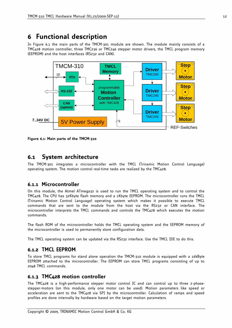
6 Functional description In Figure 6.1 the main parts of the TMCM-301 module are shown. The module mainly consists of a TMC428 motion controller, three TMC236 or TMC246 stepper motor drivers, the TMCL program memory (EEPROM) and the host interfaces (RS232 and CAN).
TMCM-310
REF-Switches
6
16
DriverTMC246
DriverTMC246
DriverTMC246
CAN
(option)
RS-232
TMCL
Memory
5V Power Supply7..34V DC
I/Os
programmable
Motion
Controllerwith TMC428
Step
Motor
Step
Motor
Step
Motor
Figure 6.1: Main parts of the TMCM-310
6.1 System architecture The TMCM-301 integrates a microcontroller with the TMCL (Trinamic Motion Control Language) operating system. The motion control real-time tasks are realized by the TMC428.
6.1.1 Microcontroller On this module, the Atmel ATmega32 is used to run the TMCL operating system and to control the TMC428. The CPU has 32Kbyte flash memory and a 1Kbyte EEPROM. The microcontroller runs the TMCL (Trinamic Motion Control Language) operating system which makes it possible to execute TMCL commands that are sent to the module from the host via the RS232 or CAN interface. The microcontroller interprets the TMCL commands and controls the TMC428 which executes the motion commands. The flash ROM of the microcontroller holds the TMCL operating system and the EEPROM memory of the microcontroller is used to permanently store configuration data. The TMCL operating system can be updated via the RS232 interface. Use the TMCL IDE to do this.
6.1.2 TMCL EEPROM To store TMCL programs for stand alone operation the TMCM-310 module is equipped with a 16kByte EEPROM attached to the microcontroller. The EEPROM can store TMCL programs consisting of up to 2048 TMCL commands.
6.1.3 TMC428 motion controller The TMC428 is a high-performance stepper motor control IC and can control up to three 2-phase-stepper-motors (on this module, only one motor can be used). Motion parameters like speed or acceleration are sent to the TMC428 via SPI by the microcontroller. Calculation of ramps and speed profiles are done internally by hardware based on the target motion parameters.
6.1.4 Stepper motor drivers The stepper motor drivers used on the TMCM-310 module without the StallGuard™ options are the TMC236 chips. These drivers are very easy to use. They can control the currents for the two phases of the stepper motors. 16x microstepping and maximum output current of 1500mA are supported by these driver ICs. On TMCM-310 modules with stallGuard™ option (TMCM-310/SG or TMCM-310/SG-CAN) the TMCM246 chips are used. These chips are fully compatible with the TMC236 chips, but have the additional stallGuard™ feature. As the power dissipation of the TMC236 and TMC246 chips is very low no heat sink or cooling fan is needed. The temperature of the chips does not get high. The coils will be switched off automatically when the temperature or the current exceeds the limits and automatically switched on again when the values are within the limits again.
6.2 Power supply The TMCM-310 is equipped with a switching voltage regulator that generates the 5V supply voltage for the digital components of the module from the motor power supply. Because of that only one supply voltage is needed for the module. The current hardware revision 2.0 of the TMCM-310 module is equipped with a protection diode against reverse polarity that shorts the power supply if it is connected with wrong polarity. The supply voltage must be 8…34V DC (V2.0). The old hardware revision 1.0 of the TMCM-310 is also equipped with a bridge rectifier. This version of the module needs the power supply voltage 9…30 V DC or 7…21 V AC. For compatibility with the new hardware revision 2.0 of the TMCM-310 also the old version 1.0 should not be powered with AC. The power supply can either be connected to the screw terminal X504 or to the power socket X500 (industry standard power socket with 2.1mm pin diameter). Both connections are electrically identical. Hardware revision and supply voltage polarity are printed on the PCB.
6.2.1 Communication interface The communication between the host and the module can be done via the RS232 interface or the optional CAN Interface. Communication with the TMCM-310 module is done using TMCL commands. The interfaces on the board are ready-to-use, so there are no external drivers or level shifters necessary. Please see chapter 4.2.3 for the pin assignments of the interfaces.
6.2.1.1 RS232
To connect the RS232 interface of the module to a PC you can use a standard null modem cable (with female plugs at both ends) or you can make a cable yourself that connects pin 2 of the TMCM-310 with pin 3 of the PC, pin 3 of the TMCM-310 with pin 2 of the PC and pin 5 of the TMCM-310 with pin 5 of the PC (so you have to cross pin 2 and 3). The baud rate of the RS232 interface can be set by software, as described in the TMCL Reference and Programming Manual. The default baud rate is default 9600bps, max. 115200bps (software selectable).
6.2.1.2 CAN
To connect the CAN interface an industry standard 10-way (2x5) ribbon cable plug (2.54mm pitch) can be used. Closing the jumper J500 terminates the CAN bus with a 120 ohms resistor. The CAN bit rate and CAN ID can be set by software (please see the TMCL Reference and Programming Manual). The maximum CAN bit rate is 500kBit/s.
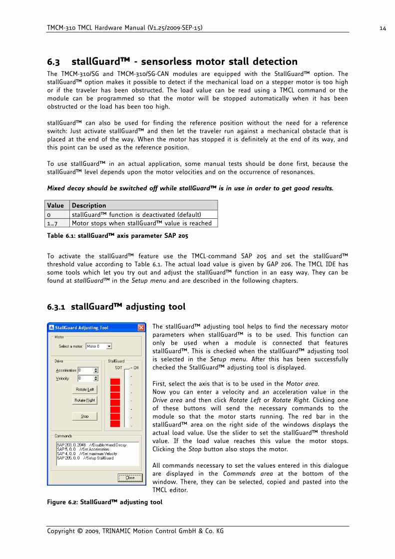
6.3 stallGuard™ - sensorless motor stall detection The TMCM-310/SG and TMCM-310/SG-CAN modules are equipped with the StallGuard™ option. The stallGuard™ option makes it possible to detect if the mechanical load on a stepper motor is too high or if the traveler has been obstructed. The load value can be read using a TMCL command or the module can be programmed so that the motor will be stopped automatically when it has been obstructed or the load has been too high. stallGuard™ can also be used for finding the reference position without the need for a reference switch: Just activate stallGuard™ and then let the traveler run against a mechanical obstacle that is placed at the end of the way. When the motor has stopped it is definitely at the end of its way, and this point can be used as the reference position. To use stallGuard™ in an actual application, some manual tests should be done first, because the stallGuard™ level depends upon the motor velocities and on the occurrence of resonances. Mixed decay should be switched off while stallGuard™ is in use in order to get good results.
Value Description
0 stallGuard™ function is deactivated (default)
1…7 Motor stops when stallGuard™ value is reached
Table 6.1: stallGuard™ axis parameter SAP 205
To activate the stallGuard™ feature use the TMCL-command SAP 205 and set the stallGuard™ threshold value according to Table 6.1. The actual load value is given by GAP 206. The TMCL IDE has some tools which let you try out and adjust the stallGuard™ function in an easy way. They can be found at stallGuard™ in the Setup menu and are described in the following chapters.
6.3.1 stallGuard™ adjusting tool
The stallGuard™ adjusting tool helps to find the necessary motor parameters when stallGuard™ is to be used. This function can only be used when a module is connected that features stallGuard™. This is checked when the stallGuard™ adjusting tool is selected in the Setup menu. After this has been successfully checked the StallGuard™ adjusting tool is displayed. First, select the axis that is to be used in the Motor area. Now you can enter a velocity and an acceleration value in the Drive area and then click Rotate Left or Rotate Right. Clicking one of these buttons will send the necessary commands to the module so that the motor starts running. The red bar in the stallGuard™ area on the right side of the windows displays the actual load value. Use the slider to set the stallGuard™ threshold value. If the load value reaches this value the motor stops. Clicking the Stop button also stops the motor. All commands necessary to set the values entered in this dialogue are displayed in the Commands area at the bottom of the window. There, they can be selected, copied and pasted into the TMCL editor.
6.3.2 stallGuard™ profiler The stallGuard™ profiler is a utility that helps you find the best parameters for using stall detection. It scans through given velocities and shows which velocities are the best ones. Similar to the stallGuard™ adjusting tool it can only be used together with a module that supports stallGuard™. This is checked right after the stallGuard™ profiler has been selected in the Setup menu. After this has been successfully checked the stallGuard™ profiler window will be shown.
First, select the axis that is to be used. Then, enter the Start velocity and the End velocity. The start velocity is used at the beginning of the profile recording. The recording ends when the end velocity has been reached. Start velocity and end velocity must not be equal. After you have entered these parameters, click the Start button to start the StallGuard™ profile recording. Depending on the range between start and end velocity this can take several minutes, as the load value for every velocity value is measured ten times. The Actual velocity value shows the velocity that is currently being tested and so tells you the progress of the profile recording. You can also abort a profile recording by clicking the Abort button. The result can also be exported to Excel or to a text file by using the Export button.
Figure 6.3: The StallGuard™ Profiler
6.3.2.1 The result of the stallGuard™ profiler
The result is shown as a graphic in the stallGuard™ profiler window. After the profile recording has finished you can scroll through the profile graphic using the scroll bar below it. The scale on the vertical axis shows the load value: a higher value means a higher load. The scale on the horizontal axis is the velocity scale. The colour of each line shows the standard deviation of the ten load values that have been measured for the velocity at that point. This is an indicator for the vibration of the motor at the given velocity. There are three colours used:
Green: The standard deviation is very low or zero. This means that there is effectively no vibration at this velocity.
Yellow: This colour means that there might be some low vibration at this velocity.
Red: The red colour means that there is high vibration at that velocity.
In order to make effective use of the stallGuard™ feature you should choose a velocity where the load value is as low as possible and where the colour is green. The very best velocity values are those where the load value is zero (areas that do not show any green, yellow or red line). Velocities shown in yellow can also be used, but with care as they might cause problems (maybe the motor stops even if it is not stalled). Velocities shown in red should not be chosen. Because of vibration the load value is often unpredictable and so not usable to produce good results when using stall detection. As it is very seldom that exactly the same result is produced when recording a profile with the same parameters a second time, always two or more profiles should be recorded and compared against each other.
6.4 Reference switches Reference switches can be used to find the reference point at startup of a system. They can be connected to the screw terminals marked STOP 0 L/R, STOP 1L/R and STOP 2 L/R. Each of the reference switch screw terminal blocks also has a GND terminal which is connected to ground and in rev.2.0 a +5V terminal for power supply for use of opener switches. Also a step loss of the system can be detected, e.g. due to overloading or manual interaction, by using a travel-switch. Pull up resistors for reference switches are included on the module. In TMCL, a reference search function is available. This reference search function supports one, two or three switches. Please see the TMCM-310 Firmware Manual for more information about the reference search function of TMCL.
6.4.1 Left and right limit switches The TMCM-310 can be configured so that a motor has a left and a right limit switch (Figure 6.4). The motor then stops when the traveler has reached one of the limit switches.
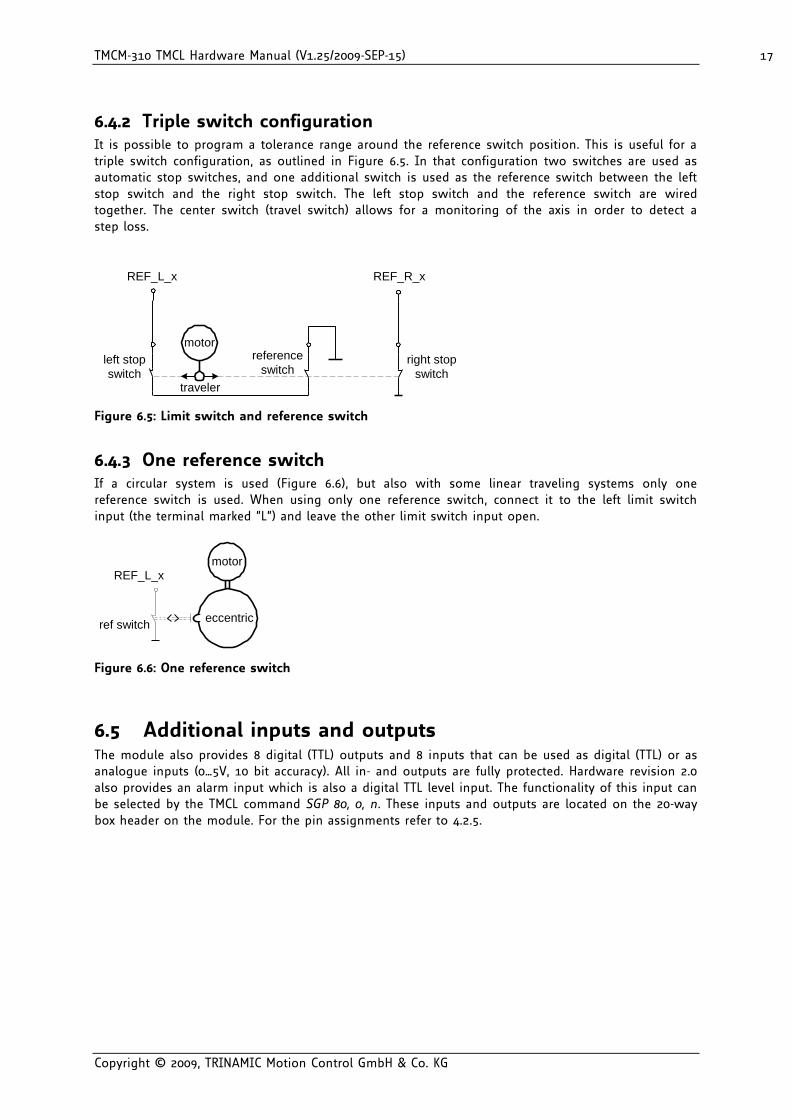
6.4.2 Triple switch configuration It is possible to program a tolerance range around the reference switch position. This is useful for a triple switch configuration, as outlined in Figure 6.5. In that configuration two switches are used as automatic stop switches, and one additional switch is used as the reference switch between the left stop switch and the right stop switch. The left stop switch and the reference switch are wired together. The center switch (travel switch) allows for a monitoring of the axis in order to detect a step loss.
left stop
switch
motor
traveler
REF_L_x
right stop
switch
REF_R_x
reference
switch
Figure 6.5: Limit switch and reference switch
6.4.3 One reference switch If a circular system is used (Figure 6.6), but also with some linear traveling systems only one reference switch is used. When using only one reference switch, connect it to the left limit switch input (the terminal marked “L”) and leave the other limit switch input open.
motor
ref switch
REF_L_x
eccentric
Figure 6.6: One reference switch
6.5 Additional inputs and outputs The module also provides 8 digital (TTL) outputs and 8 inputs that can be used as digital (TTL) or as analogue inputs (0…5V, 10 bit accuracy). All in- and outputs are fully protected. Hardware revision 2.0 also provides an alarm input which is also a digital TTL level input. The functionality of this input can be selected by the TMCL command SGP 80, 0, n. These inputs and outputs are located on the 20-way box header on the module. For the pin assignments refer to 4.2.5.
6.6 Microstep resolution The microstep resolution can be set using TMCL software. The default setting is 64 microsteps which is the highest resolution. To set the microstep resolution with TMCL, use instruction 5: SAP, type 140: microstep resolution. You can find the appropriate value in Table 6.2.
Value microsteps
0 Do not use: for fullstep please
see fullstep threshold
1 Halfstep (not recommended)
2 4
3 8
4 16
5 32
6 64
Table 6.2: Microstep resolution setting
Despite the possibility to set up to 64 microsteps, the motor physically will be positioned to a maximum of about 24 Microsteps, when operated in 32 or 64 microstep setting.
6.7 Jumpers, other connectors and LEDs
6.7.1 Blank time The blank time of the TMC236 or TMC246 motor drivers can be set using the jumpers Blank1 and Blank2. The following blank times can be set:
Blank1 Blank2 Blank time
close close 0.6µs
open close 0.9µs
close open 1.2µs
open open 1.5µs
Table 6.3: Blank time settings
Normally the shortest blank time (both jumpers closed) gives best microstepping results, but with some motors or for EMC reasons it can be necessary to set a longer blank time. Please see the TMC236 or TMC246 data sheet for more information about this matter.
6.7.2 Programmer connector and jumper J101 (rev. 1.1) On hardware rev. 1.1, the programmer connector (2x3-way header marked with Programmer on the board) serves for two purposes: either for reprogramming the CPU or for attaching other external devices with SPI interface.
If jumper J101 connects pins 1 and 2, the programmer connector can be used to reprogram the microcontroller using an Atmel ISP programmer. This is to be done by TRINAMIC only! Do not use an ISP to update the TMCL operating system. Updating can be done by the user only via the RS232 interface, using the TMCL IDE.
If the jumper J101 connects its pins 2 and 3 the programmer port can be used to attach external devices with SPI interface. To access such a device special software drivers must be written. Please get in touch with the Trinamic customer support if you wish to attach external SPI devices.
For the pin assignment of the SPI connector refer to 4.2.4.
6.7.3 Programmer connector (rev. 2.0) On hardware rev. 2.0, the programmer connector also serves for two purposes: for reprogramming the CPU (by Trinamic only) and for connecting external SPI devices (together with the soldering holes X102).
For reprogramming the CPU, an Atmel ISP programmer can be connected here. This is to be done by TRINAMIC only! Do not use an ISP to update the TMCL operating system. Updating can be done by the user only via the RS232 interface, using the TMCL IDE.
To use this connector for connecting external SPI devices, the SPI MISO, MOSI and CLK lines must be connecting to this port. The +5V and GND pins of this connector can also be used for powering the external SPI device. The connector X102 (soldering holes) provides the chip select lines for the external SPI devices (Pin 1 = SPI_SELECT0, Pin 2 = SPI_SELECT1, Pin 3 = SPI_SELECT2). To access such a device special software drivers must be written. Please get in touch with the Trinamic customer support if you wish to attach external SPI devices.
For pin assignment of the SPI connector refer to 4.2.4.
6.7.4 SPI jumpers With hardware revision 1.1 of the TMCM-310, the jumpers marked SCK, SDI, SDO and SCS can be used to disconnect the TMC428 from the microcontroller. This feature can be used to connect the TMC428 to a different CPU. Please get in touch with the Trinamic customer support if you wish to do so. Normally this is not needed and all these jumpers always have to be closed. On hardware revision 2.0 these jumpers have been eliminated, but it is still possible to connect a different CPU, by cutting four wires on the PCB. Please get in touch with TRINAMIC if you wish to do this.
6.7.5 Shutdown jumper The shutdown jumper only exists on hardware revision 1.1 of the TMCM-310. When this jumper is closed, the motor drivers are always enabled. When this jumper is open the enable signal of the motor drivers can be controlled by the CPU so that the CPU can shut down the drivers (using the shutdown functions in TMCL). Normally this jumper is closed. On hardware revision 2.0 of the module the shutdown jumper has been replaced by the alarm input on the additional input/output connector of the module. Please see chapter 6.5 for more information about this input.
6.7.6 Reset button Pressing the reset button interrupts all tasks and re-starts the TMCL operating system which then re-initializes the module. So, pressing the reset button has the same effect as cycling the supply voltage.
6.7.7 Power LED The power LED (D503) lights steadily when the TMCM-310 is powered.
6.7.8 Activity LED The activity LED (D100) flashes when the TMCM-310 is running normally. During a firmware upgrade process the LED lights steadily.
7 Putting the TMCM-310 into operation On the basis of a small example it is shown step by step how the TMCM-310 is set into operation. For more detailed instructions refer to the TMCM-310 Firmware Manual please. Users who are already familiar with TMCL and other Trinamic modules may skip this chapter. Example: The following application is to be implemented on the TMCM-310 module using the TMCL-IDE Software development environment. For data transfer between the host PC and the module the RS-232 interface is employed. A formula how speed is converted into a physical unit like rotations per seconds can be found in chapter 8.1. The simple application is:
Turn Motor 0 left with speed 500
Turn Motor 1 right with speed 500
Turn Motor 2 with speed 500, acceleration 5 and move between position +10000 and –10000. To implement this simple application on theTMCM-310 it is necessary to do the following things: Step 1: Connect the RS-232 Interface to the PC Step 2: Connect the motors to the motor connectors Step 3: Connect the power supply voltage to the power connector Step 4: Switch on the power supply. The power LED should light up and the activity LED
should start to flash. This indicates the correct configuration of the microcontroller. Step 5: Start the TMCL-IDE Software development environment. Open file test2.tmc or enter
the program shown in the following listing manually. A description of the TMCL commands can be found in the TMCL Reference and
Programming Manual. Step 6: Click the Assemble icon to convert the TMCL program into byte code. Then download the program to the TMCM-310 module by clicking the Download icon. Step 7: Click the Run icon. The downloaded program will now be executed. A detailed documentation about the TMCL operations and the TMCL IDE can be found in the TMCL Reference and Programming Manual. The next chapter shows how the velocity and acceleration values are calculated.
//test2.tmc – A simple example for using TMCL and the TMCL-IDE
ROL 0, 500 //Rotate motor with speed 500
WAIT TICKS, 0, 500
MST 0
ROR 1, 500 //Rotate to other direction with same speed
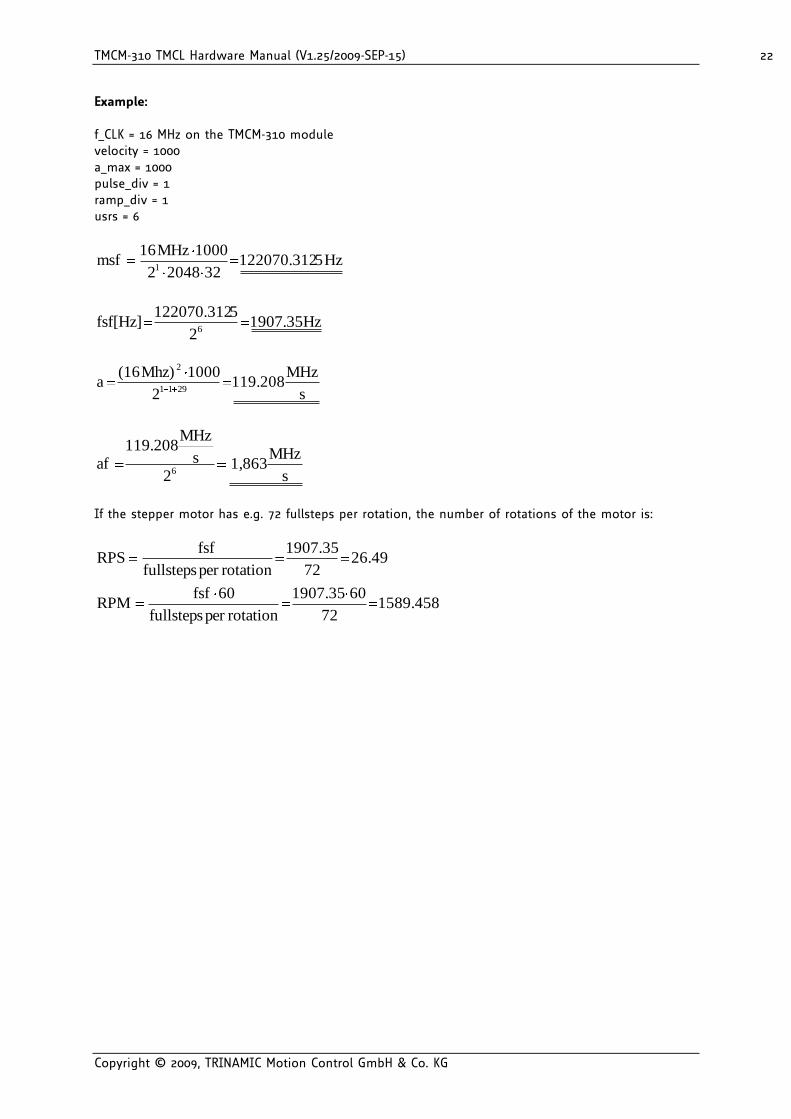
8.1 Calculation: velocity and acceleration vs. microstep- and fullstep frequency
The values of the parameters sent to the TMC428 do not have typical motor values, like rotations per second as velocity. But these values can be calculated from the TMC428 parameters, as shown in this document. The parameters for the TMC428 are:
Parameter Description Range
fCLK Clock frequency 16 MHz
velocity 0…2047
a_max Maximum acceleration 0…2047
pulse_div Velocity pre-divider. The higher the value is, the less is the maximum velocity. Default value = 3 Can be changed in TMCL using SAP 154.
0…13
ramp_div Acceleration pre-divider. The higher the value is, the less is the maximum acceleration default value = 7 Can be change in TMCL using SAP 153.
0…13
Usrs Microstep resolution (microsteps per fullstep = 2usrs). Can be changed in TMCL using SAP 140.
0…6
Table 8.1: TMC428 Velocity parameters
The microstep-frequency of the stepper motor is calculated with:
3220482
velocity[Hz]fusf[Hz]
pulse_div
CLK with usf: microstep-frequency
To calculate the fullstep-frequency from the microstep-frequency, the microstep-frequency must be divided by the number of microsteps per fullstep:
usrs2
usf[Hz]fsf[Hz] with fsf: fullstep-frequency
The change in the pulse rate per time unit (pulse frequency change per second – the acceleration (a) is given by:
9 TMCL TMCL, the Trinamic Motion Control Language is used to send commands from the host to the TMCM-310 module and to write programs that can be stored in the EEPROM of the module so that the module can execute the TMCL commands in a stand-alone mode. TMCL is described in a separate documentation, the TMCL Reference and Programming Manual. This document also describes the TMCL Integrated Development Environment (TMCL IDE), a program running on Windows which allows easy development of TMCL applications. All the manuals are provided on the TMC TechLib CD and on the web site of Trinamic (http://www.trinamic.com). Also the latest versions of the firmware (TMCL operating system) and PC software (TMCL IDE) can be found there.
10 Differences between hardware rev. 1.1 and 2.0 There are two versions of the TMCM-310: hardware rev 1.1 and hardware rev. 2.0. Both of these versions of the TMCM-310 are compatible with each other, but there are some slight differences. These differences are:
Power supply: rev. 1.1 is equipped with a bridge rectifier, and thus the polarity of the supply voltage does not matter and can even be alternating current. But as this caused problems when connecting external SPI devices (grounding problems), the rectifier has been eliminated on hardware revision 2.0. The rev. 2.0 module is equipped with a diode that protects the module against wrong polarity (the supply voltage will be shorted if the polarity is wrong!).
Alarm input: rev 1.1 is equipped with a jumper that controls the shutdown functions of the motor drivers. On rev. 2.0 this jumper has been eliminated. Instead, an alarm input has been introduced on the additional I/O connector. This leads to more flexibility, as the functionality of this input can be configured by TMCL. It also makes the external I/O connector fully compatible with the one on the TMCM-610 and TMCM-612.
Connecting external SPI devices: This has been simplified on hardware rev.2.0 of the TMCM-310 module. Please see chapter 6.7.3 for more information about this.
SPI jumpers: As these jumpers were hardly needed they have been eliminated on hardware rev. 2.0 and replaced by cuttable PCB wires and soldering pads.
Voltage regulator: The voltage regulator of the module has been improved for better EMC behavior.
The hardware revision number is printed on the back of the PCB.